DEVELOPMENTS IN STIRRED MEDIA MILLING … · DEVELOPMENTS IN STIRRED MEDIA MILLING TESTWORK AND...
19
1 DEVELOPMENTS IN STIRRED MEDIA MILLING TESTWORK AND INDUSTRIAL SCALE PERFORMANCE OF OUTOTEC HIGMILL Harri Lehto, Outotec, Finland Benjamin Musuku, FQM Kevitsa Mining Oy, Finland Ville Keikkala, Outotec , Finland Pekka Kurki, Outotec , Finland Andres Paz, Outotec, Australia ABSTRACT Outotec has introduced a new technology and concept for fine grinding applications. This technology is based on existing, well proven stirred milling technology earlier being only available for white minerals processing. After launching this new fine grinding technology for the metalliferrous mineral processing industry, Outotec started an intensive testing campaign with two pilot mills, and the test results have been both promising and interesting. Outotec has continued test work developments from a large scale to a smaller scale tests. In February 2015, First Quantum Minerals (FQM) commissioned a new fine grinding circuit to boost the metallurgical performance of its Kevitsa copper/nickel operation in Finland. The heart of this circuit is a 700 kW Outotec HIGmill producing a 20 μm regrind product to enhance particle liberation for improved downstream flotation performance. The start-up of this fine grinding circuit provides a unique opportunity for scale-up evaluation. This paper discusses the main outcomes of the recent developments of test validations and benchmark against industrial size unit, as well as discusses the overall performance of HIGmill in Kevitsa concentrator plant. Keywords; Grinding, fine grinding, energy efficiency, regrinding, concentrate. INTRODUCTION Outotec has intensively studied different options for more efficient fine grinding technology. This includes incremental development steps in conventional grinding technology as well as new technology. New technology became reality in April 2012 when Outotec launched a new fine grinding technology, Outotec HIGmill™, targeting for the mineral processing industry. This new technology has an excellent and relatively long history and references in ultra fine and fine grinding, but so far its use has been only limited to calcium carbonate grinding, until Swiss Tower Mill Minerals (STM) acquired rights for its application in mineral processing. Further development and intensive test work has brought this technology to the minerals processing industry. Outotec, having exclusive global rights for this technology, is proudly presenting an update of this technology and showing summary of the recent test work. In addition a new approach in fine grinding control philosophy, is also presented. Fine grinding technology use in the mineral process industry has increased over the last 10 years. This can be mainly attributed to processing finer grained ore bodies, which requires a finer grind for valuable mineral liberation.
Transcript of DEVELOPMENTS IN STIRRED MEDIA MILLING … · DEVELOPMENTS IN STIRRED MEDIA MILLING TESTWORK AND...

1
DEVELOPMENTS IN STIRRED MEDIA MILLING TESTWORK AND INDUSTRIAL SCALE PERFORMANCE OF OUTOTEC HIGMILL
Harri Lehto, Outotec, Finland
Benjamin Musuku, FQM Kevitsa Mining Oy, Finland
Ville Keikkala, Outotec , Finland
Pekka Kurki, Outotec , Finland
Andres Paz, Outotec, Australia
ABSTRACT
Outotec has introduced a new technology and concept for fine grinding applications. This technology is based on existing, well
proven stirred milling technology earlier being only available for white minerals processing. After launching this new fine
grinding technology for the metalliferrous mineral processing industry, Outotec started an intensive testing campaign with two
pilot mills, and the test results have been both promising and interesting. Outotec has continued test work developments from
a large scale to a smaller scale tests.
In February 2015, First Quantum Minerals (FQM) commissioned a new fine grinding circuit to boost the metallurgical
performance of its Kevitsa copper/nickel operation in Finland. The heart of this circuit is a 700 kW Outotec HIGmill producing
a 20 µm regrind product to enhance particle liberation for improved downstream flotation performance. The start-up of this
fine grinding circuit provides a unique opportunity for scale-up evaluation.
This paper discusses the main outcomes of the recent developments of test validations and benchmark against industrial size
unit, as well as discusses the overall performance of HIGmill in Kevitsa concentrator plant.
Keywords; Grinding, fine grinding, energy efficiency, regrinding, concentrate.
INTRODUCTION
Outotec has intensively studied different options for more efficient fine grinding technology. This includes incremental
development steps in conventional grinding technology as well as new technology. New technology became reality in April
2012 when Outotec launched a new fine grinding technology, Outotec HIGmill™, targeting for the mineral processing industry.
This new technology has an excellent and relatively long history and references in ultra fine and fine grinding, but so far its
use has been only limited to calcium carbonate grinding, until Swiss Tower Mill Minerals (STM) acquired rights for its
application in mineral processing. Further development and intensive test work has brought this technology to the minerals
processing industry. Outotec, having exclusive global rights for this technology, is proudly presenting an update of this
technology and showing summary of the recent test work. In addition a new approach in fine grinding control philosophy, is
also presented.
Fine grinding technology use in the mineral process industry has increased over the last 10 years. This can be mainly attributed
to processing finer grained ore bodies, which requires a finer grind for valuable mineral liberation.

2
TECHNOLOGY BENEFITS
Outotec HIGmills™ are based on a well proven technology which has been developed during the last three decades.
Largest units available. There are over 200 units installed, including 9 mills with 5000 kW installed
power. To date these are the largest fine grinding units in operation.
Operational flexibility. All HIGmills are equipped with VFD, which is the heart of the on-line power
draw control. Based on massive continuous test work campaigns this enables even a single unit to operate
succesfully with very fluctuating process conditions. HIGmills can be used with different grinding media,
from ceramic ones to steel, with sizes from 1 mm to 12 mm.
Simple process design. Due to its unique vertical structure, including 15-20 grinding stages in the form of
rotating grinding rotors , stationary ring combinations, external classification is not needed. A simplified
HIGmill flow sheet is presented in Figure 1.
High Energy efficiency. The unique design of the rotors and counter rings in a vertical arrangement
enables high power intensities even with relatively low tip speeds. Power intensities 200 – 300 kW / m3
are typical. Operational tip speeds are in the range between 6 – 12 m/s, depending on application and mill
size.
Figure 1. Simplified HIGmill™ flow sheet (Outotec, 2012)
OUTOTEC HIG MILL
Mill structure Outotec HIGmill™ is a “stirred media” grinding mill, in where the stirred effect is caused by rotating grinding rotors together
with static counter rings. General structure is presented in Figure 2. Mill structure and operational description has been recently
presented in several papers and publications (Erb 2015, Keikkala 2015, Lehto 2014, 2013a, 2013b, Roitto 2013, Junnola 2013),
and for that reason those are presented very briefly in this paper.

3
Operational Description
60-75 % of the mill free volume is filled with grinding media (beads) that is typically 1-6 mm ceramics, with a density of about
4 g/cm3. The slurry is pumped into a grinding chamber via the feed inlet from the bottom of the grinding chamber. The
combination of slurry concentrate, grinding media (beads) and rotating grinding rotors provides momentum to stir the charge
against a series of stationary counter rings. The particles are ground mostly by attrition breakage between the beads. (Napier-
Munn et al., 2005) . Due to the vertical arrangement of the mill, classification is conducted simultaneously throughout the
grinding process with larger particles remaining longer at the peripheral, while smaller particles move upwards. This
phenomenon enables simple process design. The process is typically a single pass with no external classification necessary.
Figure 2 Outotec HIGmill™. (Outotec, 2013)
The grinding rotor configuration and the whole chamber geometry have been optimized for efficient energy transfer to the bead
mass, internal circulation and classification.
Make-up grinding media is fed to the mill together with feed slurry or from the top. The product discharges at atmosphere at
the top of the mill. The combined cyclone overflow and mill discharge are the circuit product.
KEVITSA COMMISSIONING AND SET UP
In February 2015, First Quantum Minerals (FQM) commissioned a new fine grinding circuit to boost the metallurgical
performance of its Kevitsa copper/nickel operation in Finland.
Kevitsa concentrator treats Ni-Cu-PGE ore through sequential flotation process for the recovery of Cu and Ni respectively.
Typical feed grades ranges from 0.24 – 0.28% Cu and 0.18 – 0.22% Ni. The PGE are distributed between the two concentrates
whereas Au predominantly reports to Cu concentrate. Concentrate grades for Cu and Ni are 25% Cu with >1% Ni and 10% Ni
respectively. The valuable minerals are generally finely disseminated in the ore body requiring a finer grind of 75% passing
75µm as feed to flotation circuit. To maintain high mill throughput (> 950 t/h), the flotation feed grind usually falls short of its
target thereby posing a challenge on selectively keeping the grade of Ni in copper concentrate below 1%. Mineralogical analysis

4
on copper final concentrates indicated that most of Ni existed as pentlandite-chalcopyrite composites, hence requiring further
liberation. The HIGmill was installed on the copper circuit as shown in figure 3, with the objective of maintaining fine grind
in the copper cleaner circuit at a coarser flotation feed with the benefit of high throughput. Copper rougher/scavenger
concentrates was determined to be the most suitable feed to HIGmill both in terms of flow and particle size distribution
Figure 3 Kevitsa Flotation circuit flowsheet (FQM Kevitsa MIne, 2015)
Grinding duty
The following table presents the project data that was used to size the mill and design the circuit.
Table 1. Kevitsa HIG design criteria. (Outotec 2014).

5
Laboratory scale test work was performed on a Kevitsa rougher concentrate test sample and Specific grinding energy (SGE)
prediction was 8-10 kWh/t. Wet screening was used to analyse psd and HIG5 laboratory pilot size unit was used for the test
work.
Based on laboratory scale test work HIG700/4000 with 700 kW installed power was chosen for this duty.
Set up
The HIGmill circuit consists of cyclone cluster with 10 cyclones; HIGmill feed tank, HIGmill product tank, bead addition
system, PSI500 particle size instrument and the HIGmill itself. The HIGmill was installed to an existing plant where there is
not too much free space. Due to versatile nature of the product placement the footprint can be maintained very small. As seen
in the picture 5, the actual HIGmill takes only about 5m x 5m of space. Auxiliaries doesn’t necessarily need actual floor space
and can be installed within the vertical footprint of the mill. Schematic set up of Fine grinding circuit is presented in Figure 4.
Figure 4. Fine grinding circuit set up in FQM Kevitsa mine (Outotec 2015)
Installation and commissioning took only two weeks. During that two week time the mill was erected and commissioned,
excluding the time needed for the foundation concrete to dry. After the two weeks’ time mill circuit was up and connected to
the existing circuit. If needed the circuit can be isolated from other process very easily. This is an advantage during
commissioning and shutdown, because all can be performed without disturbing the downstream process.
In the first start the mill feed was purely water and it was 100% operating without introducing slurry to the circuit. When the
change from water to slurry occurs the cyclone underflow is controlled as long as the feed to the mill was at the desired level
Control philosophy
After the commissioning and some power calibration trials, the mill was operated with a constant speed / constant power. After
a couple of weeks of operation a unique but simple control philosophy was taken into use. There are basically two options to
perform the HIGmill speed control using the main motor variable frequency drive (VFD). One is to control the mill power
draw directly based on on-line particle size analysis and adjusting mill speed accordingly. The second more sophisticated

6
procedure is to use Specific grinding energy (SGE) set point for incoming feed tonnage. This is the preferred control method
by Outotec, because it acts as feed forward control, for fluctuating feed tonnage from upstream process.
Both methods have been tested at the plant and most of the time SGE set point control philosophy has been used. SGE based
control philosophy is described below.
A set point for the (SGE) is given in order to achieve the target product fineness. Feed forward control principle is used by
measuring HIGmill feed dry feed quantity utilizing flow and density measurements and adjusting the mill shaft speed (tip
speed) to reach target SGE per total fine grinding feed flow. This principle ensures the target SGE is reached at all times even
in fluctuating feed rate conditions. The feedback control principle is used by measuring the particle size distribution on-line by
using particle size analyser technology (PSI500). On-line particle size measurement is used to control the particle size of the
slurry flow to downstream processes. If the product size is out of the target set (coarser or finer), the new set point to the SGE
is given. If there is no PSD on-line measurement utilised, the changing of the SGE set point is based on laboratory analysis.
If the power draw demand permanently changes, the bead load is increased to a new level so that motor speed is close to the
optimal. The make-up grinding beads are fed continuously to the mill directly through the open top of the mill, avoiding pipeline
blockages.
At the moment the mill speed is being controlled related to the dry tons fed to the mill. Operator gives set point as SGE (kWh/t)
for the ore. This kWh/t is based on the knowledge of the ore which can be updated according to the analyses from the mine.
Even small fluctuations in the slurry throughput affect the mill speed. The measurement point for the density is located just
before the mill. Therefore the changes in the VFD which control the mill speed take immediately for the coming slurry.
Figure 5. Photos from site. (Outotec 2015)

7
Outotec also provides a multivariable, predictive and statistical control system known as Advanced Control Technology (ACT)
for the HIGmill. With this methodology, the control is based on SGE value which is being constantly updated. This method is
the most recommended due to its nature not to control only the mill but it takes into account all the equipment related to the
tertiary grinding circuit. When using ACT operator only needs to start and stop the mill with a sequence, otherwise the mill
adapts itself to the process. ACT takes into account: cyclone battery pressure and classification, feed flow and density, mill and
slurry temperature and feed and product sizes. ACT also controls all the interlocks. ACT adapts data gathered from all the
equipment which are related to HIGmill circuit and adjusts the circuit accordingly. This is especially important when the quality
and type of ore changes, as it typically does.
Based on the feedback received from the operators the mill circuit is very easy to control. Start-up is being done with a
predefined sequence. The sequence takes into account pumps, valves, mill, cyclones, oil temperatures etc. Basically the operator
only needs to press “Start” and the whole mill circuit is up and running with the predefined SGE. The circuit doesn’t need any
attention from the field operators. The shutdown sequence takes into account accordingly all the above mentioned points and
also flushes the mill for next start up.
Initial bead charge for the mill is fed from the top of the mill. Depending on the desired grind size and mill setup the grinding
bead volume is something between 40-70%. The grinding bead addition is done via top of the mill. At Kevitsa the bead addition
is done once in an hour, based on the consumed power of the mill, with the feed slurry. The beads are transferred to the grinding
chamber in a controlled manner using a dosing system with a screw feeder.
Due to the unique design of the mill no media beads escape from the top of the mill, with the discharge slurry. When there is
a longer shut down required, the beads are cleaned with flushing water as a part of the normal stopping sequence. After that
the beads are drained via the bottom valve of the mill and can be used again as an initial charge or addition to the mill.
HIGmill has been in continuous operation since commissioning for about a year. There has been constant development for the
liners and rotors to last with this type of ore as long as possible. With the current setup the estimated wear life of the
consumables is as follows:
Five bottom rotors >6 months
Rest of the rotors >12 months
Bottom liner >12 months
Rest of the liners ~18 months.
It is possible to replace only the needed shell liners and grinding rotors. A full change out of all the grinding rotors takes less
than 24 hours. The bottom rotors or bottom shell liners can be changed within one 12 shift.
In order to open the mill it first must be emptied of the beads and water. First the bottom plate with feed inlet from the grinding
chamber. After removing all the bolts from the mill shells the mill halves can be separated. The halves are flanged so that the
HIGmill opens like “clam shell”. When the halves are opened the shaft with the grinding rotors is visible. The shaft is lowered
down with the winches installed on the HIGmill. Then a spare shaft can be installed immediately or the used shaft can be
transported to the workshop for the grinding rotor relacement. The rotors can be removed by attaching the shaft to the horizontal
stand. The rotors slide from the shaft and the new rotors can be installed the same way by sliding back to the shaft.
KEVITSA PERFORMANCE
The HIGmill has been effective in particle size reduction while preserving the conducive mineral surface characteristics. The
P80 has been in the range of 30 -40 µm with F80 being around 90-110 µm influenced by type of ore (Fig, 6). When looking at
the on-line particle sizes one should remember that the on – line analysis in Kevitsa is only over the mill, measuring actual Mill
feed (cyclone U/F) and mill product. The total product out of the fine grinding circuit is combined product of Cyclone O/F and
Mill product. From the graph in Fig 6, it can also be clearly seen how the mill, with SGE control operates even in fluctuating
conditions keeping P80 almost constant with F80 fluctuating quite heavily. The data points are 10 min avg values taken from
3 days of normal operation.

8
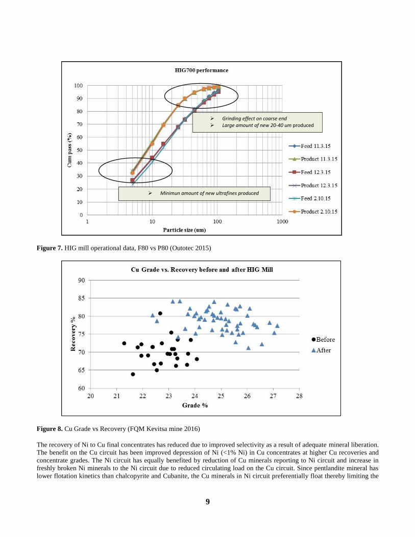
Figure 7 shows couple of examples of the grinding performance over the circuit; Circuit feed vs. Circuit product. This shows
clearly that the effect has been on a coarser end, without producing too much new ultrafine particles.
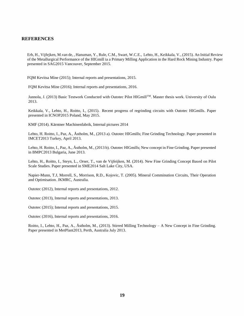
There has been a remarkable improvement of Cu recovery and grade after the mill was installed. This is attributed to adequate
liberation of minerals without altering the flotation characteristics. The circulating load in the Cu cleaning circuit reduced
remarkably with benefits of improved overall circuit stability. The sensitivity of finer flotation feed grind has been reduced as
well, allowing for a higher mill throughput at slightly coarser grind than before. Extra capacity on the Cu scavenger cells has
been created by increased pulling rates to allow coarser concentrate to be fed to HIGmill, translating into improved Cu
recoveries. The general froth structure on the Cu cleaner circuit has improved and this can be attributed to enough fine
generation for froth stability. (Figure 8).
Figure 6. HIG mill operational data, F80 vs P80 (Outotec 2015)
9
Figure 7. HIG mill operational data, F80 vs P80 (Outotec 2015)
Figure 8. Cu Grade vs Recovery (FQM Kevitsa mine 2016)
The recovery of Ni to Cu final concentrates has reduced due to improved selectivity as a result of adequate mineral liberation.
The benefit on the Cu circuit has been improved depression of Ni (<1% Ni) in Cu concentrates at higher Cu recoveries and
concentrate grades. The Ni circuit has equally benefited by reduction of Cu minerals reporting to Ni circuit and increase in
freshly broken Ni minerals to the Ni circuit due to reduced circulating load on the Cu circuit. Since pentlandite mineral has
lower flotation kinetics than chalcopyrite and Cubanite, the Cu minerals in Ni circuit preferentially float thereby limiting the
Grinding effect on coarse end Large amount of new 20-40 um produced
Minimun amount of new ultrafines produced

10
residence time for Ni minerals which translates into loss of Ni recovery. Therefore, keeping most of Cu minerals out of the Ni
circuit has created enough residence time for Ni minerals.(Figure 9).
Figure 9. Ni Grade vs Recovery (FQM Kevitsa mine 2016)
TEST PROCEDURES AND UNITS AVAILABLE
Pilot Mills
Outotec can serve customers with several size pilot test units including HIG5, HIG25 and HIG75 ranging from 5 to 75 kW
installed power. Pilot units can also be supplied which are fully equipped small scale HIGmills designed to be used as for on-
site testing campaigns. Mills are available with different type of internals; standard internals and coarse internals. Internals
refer to different grinding rotor -counter ring designs. Coarse internals have been especially designed for coarse feed
applications, up to about F80 300-600 µm enabling use of coarser media beads, up to 12 mm. At the moment pilot units are
operated in Mexico, South Africa, Australia, Germany, Austria and Finland.
Pilot units are presented in figures 10 and 11.

11
Figure 10. HIG25 container unit. (Outotec, 2013).
Figure 11. Outotec HIG 5 test set up (left)(Junnola 2013), and HIG 75_200 (right) (KMF 2014)
Test Procedures
Three different test procedures, continuous, semi-continuous and small sample test are used to measure the grindability in the
HIGmillTM. Continuous test is preferred whenever possible but usually there is not enough test material to use that method.
Most of the tests are made in semi continuous form. Short test descriptions are presented below.
Continuous test
A continuous test can be performed with all test units, and its the easiest, most straight forward method, when enough test
material is available. A mixing tank is used for preparing of the slurry of desired milling density, and for homogenising the
feed material. Milling density will be adjusted according solids density. Density is measured and confirmed before the grinding
test when the slurry is pumped in closed circuit and corrected if necessary.

12
Slurry is pumped through the mill chamber with a hose pump. The pump speed is adjusted based on pump calibration curves
according the target flow rate / retention time.
Other operational parameters are adjusted according to pre-defined test plan. Test plan is made in order to produce performance
graph which covers the target SGE (Specific Grinding Energy, kWh/t) range producing target particle size (P80 and/or P50,
µm).
Milling density (% w/w solids) and flow rate (m3/h) are measured from mill discharge, each time before sampling. Pump speed
setting is not adjusted if the measured flow rate is within +/- 5 % from target and measured data is used for calculation. Mill
power draw is recorded to the data logging system. Both torque and motor based data are recorded but the report is based on
torque.
Sampling sequence is defined as a minimum of 4 times flow rate/mill free volume to ensure balanced conditions in a mill after
parameter adjustments.
After each sampling point, operational parameters are changed according the test plan. Normally only the tip speed is adjusted
for a new SGE point, but also the milling density or flow rate can be adjusted.
Samples will be marked and stored for the particle size analysis. Particle size analysis are made with laser or wet screening.
Semi-continuous test
In a semi-continuous test run, the sample to be tested is fed several times (steps) through the mill with one set of parameters
and constant SGE. This procedure needs two mixing tanks for a slurry.
Mill discharge is stored in mixer 2, which is used as a feed material in the next grinding step. SGE is increased cumulatively
in steps, and sampling is performed during each grinding step. This procedure is used typically with a smaller test unit, HIG 5.
Small sample test
Over the years it has been noticed that having a small sample test is a must to have. Target with a small sample test was to
utilise the material amount which is able to be produced even from a series of laboratory scale flotation test work. Target was
to develop a test method able to be performed with only couple of kilos of sample, still maintaining continuous flow test nature.
This has been done and the following procedure can be performed with about 4 kg of dry solids, depending solids sg value.
Small sample test is performed using HIG5 laboratory mill.
The test sample is characterised by measuring sample particle size and solids density, as per in the continuous and semi-
continuous tests. The test mix with a desired slurry slurry density is mixed in a mixer, and added into a mill (HIG5) including
pre set amount and size of grinding media. Mill is closed and slurry is circulated (pumped) through the mill, and some water is
added to maintain target flowrate during grinding.
The mill is then operated according to test plan for a certain time, and the used kWh are recorded.. After each grinding step the
mill is emptied and the beads is separated from the slurry. A subsample is then divided from the slurry for particle size analysis.
The remained slurry can be filtered to be the feed for next grinding step.
The small sample test consist of five grinding steps, grinding times are typically (1), 2, 4, 8 and 12 minutes.
Operational parameters, grinding media material and size in small sample test depends of the feed particle size and also of
desired product size, like in any other test procedures. Tip speed is chosen to cover the target specific grinding energy range.
Test results from any of these tests are presented as performance graph (see fig 12). The performance graph is used for mill
sizing.

13
Figure 12. Performance graph. (Lehto, 2012).
SITE SURVEYS There has been several different test campaigns for follow up and optimisation of HIGmill operation in Kevitsa mine in Finland,
and also to produce data for a specific HIGmill power model development. Three of the test campaigns have been focused
especially for a scale up verification from the laboratory scale tests with HIG5 against industrial size unit in Kevitsa, Sampling
campaigns were performed in April, October and December 2015.
There has also been several other test campaigns recently with HIG75 and also with HIG25 unit, and some of those results are
presented in separate papers.
Verification sampling was performed over the Fine grinding circuit (see Fig 4). Circuit feed or HIGmill feed (scalping cyclone
U/F) or both were collected for a lab scale tests, and smaller samples for a particle size analysis. Samples were taken typically
during 2 hours of steady operation.
All the samples were sent to Outotec Research Center (ORC) in Pori, Finland. Particle size analysis were made by wet screening
followed by Malvern laser sizing (< 20 µm fraction). All the samples were measured with same procedure.
Semi continuous test procedure was used as main test procedure in scale up verification tests.
During the sampling, the related process data was collected and used as average process data to make a comparison between
laboratory data and the full scale process.
The other verification was performed for a verification of a small sample test procedure, and semi continuous test procedure.
Although this is still ongoing process, some of the results are presented already in this paper.
The graph in Figure13 presents the result from a first campaign, made in April 2015. The feed material for laboratory testing
has been circuit feed, while the sampled full scale plant has been overall circuit product (combined cyclone overflow and mill
discharge). The process data has been taken from 3 different pre planned operating (SGE) points. 3 semi-continuous tests were
performed and the performance is practically one to one from laboratory to full scale. Process points for P80 values 13 µm, 14
µm and 15 µm are 13,6 kWh/t; 18,5 kWh/t and 22,1 kWh/t, and power regression points from pilot scale tests are 14,5 kWh/t;
17,7 kWh/t and 20,4 kWh/t.

14
Figure 13. Scale up tests April 2015 (HIG5 vs HIG700)
This graph also proves that the initial laboratory scale results, used as design basis (table 1) ,8-10 kWh/t for P80 20 µm , has
been met.
Figure 14. Scale up tests April 2015 (HIG5 vs HIG700)
Figure 14 presents the result from a same test campaign, with the same procedure, but made for mill feed (cyclone U/F). The
comparison of the SGE to achieve a P80 value of 18 µm good between laboratory and full scale operation (25,5 kWh/t vs. 27,3
kWh/t). The reason the SGE reported is higher in Figure 14, compared to Figure 13, is simply that SGE in Figure 13 is
calculated based on circuit feed, while SGE in Figure 14 is calculated based on cyclone underflow which is clearly lower (t/h).

15
Figure 15. Scale up results October 2015 (HIG5 vs. HIG700)
Same procedure was performed for a HIGmill feed in October 2015 , and the result is excellent, showing only minor difference
in target P80 20 µm process value 29,0 kWh/t vs laboratory 28,2 kWh/t. This reported laboratory value is taken from power
regression graph. (Fig 15).
Figure 16., Scale up results December 2015
In December 2015 the same procedure was used again for a HIGmill feed sample, still showing relatively good and close results
with the semi – continuous (ORC-SC56) test result. In addition an excellent results is that small sample test (ORC Batch 25) is
almost one to one match with full scale operating mill process data.

16
As mentioned earlier the other verification on samples from different deposits than Kevitsa were performed for the small sample
test procedure against semi continuous test procedure. The first results are presented in Figures 17, 18 and 19, and individual
test points in Table 2.
Figure 17. Semi continuous test vs. Small scale test with copper concentrate,
Figure 18. Semi continuous test vs. Small sample test with platinum concentrate.
Figure 19. Semi continuous test vs. Small sample test with copper-gold concentrate.

17
Once again, although there is some minor fluctuations in individual test points, the trend curve (power regression) proves to be
a good match for all results presented in Figures 17, 18 and 19. The outcome of these tests is that we are now more confident
of using the laboratory HIGmill for a small sample test, than for example batch ball mill. Most importantly the results prove
that sizing can be performed also with a small sample, especially the typical P80 range between 20 – 45 µm, with acceptable
accuracy.
Table 2. Test data for graphs presented in figures 17, 18 and 19.
P80 Batch 17 P80 SC54&57 P80 Batch 17 SC54&57
um kWh/t um kWh/t um kWh/t kWh/t
63 4,3 39 7,6 60 5,0 4,6
43 9,1 36 10,1 55 5,7 5,3
26 17,7 34 12,7 50 6,5 6,1
18 26,9 66 3,5 45 7,6 7,3
60 5,3 40 9,0 8,8
45 7,1 35 10,9 10,9
42 8,9 30 13,6 14,0
25 17,6 18,9
Test data points Power regression
P80 Batch24 P80 SC61-15 P80 Batch24 SC61-15
um kWh/t um kWh/t um kWh/t kWh/t
39 1,6 28 3,7 35 3,1 2,5
35 3,5 26 7,3 32 3,7 3,2
29 7,1 20 10,9 29 4,6 4,2
17 14,4 18 14,3 26 5,8 5,5
13 21,2 16 17,7 23 7,5 7,6
20 10,2 11,0
Test data points Power regression
P80 Batch11 P80 SC53-15 P80 Batch11 SC53-15
um kWh/t um kWh/t um kWh/t kWh/t
56 6,9 44 8,6 50 9,7 8,7
44 14,5 38 16,4 45 11,3 10,5
22 29,5 32 23,7 40 13,4 12,8
17 44,1 24 31,3 35 16,2 16,1
20 38,6 30 20,1 21,1
25 26,0 28,8
Test data points Power regression

18
CONCLUSIONS
In February 2015, First Quantum Minerals (FQM) commissioned a new fine grinding circuit to boost the metallurgical
performance of its Kevitsa copper/nickel operation in northern Finland. The heart of this circuit is a 700 kW Outotec HIGmill
(HIG 700/4000) targeting to a P80 of 20 µm product to enhance particle liberation for improved downstream flotation
performance.
Commissioning and ramp up has been very fast and successful, and the targets have been clearly met, from energy efficiency
perspective and also from metallurgical performance perspective. Outotec developed control philosophy for on-line controlling
of the particle size in fine grinding circuit has been tested, and this concept has also been proved to be applicable.
Several sampling campaigns have been performed for a follow up and also to optimize the circuit operation together with FQM
personnel in Kevitsa. Scale up verification has been progressing significantly, and also new small sample test method has been
developed. There has also been an important development with a new grinding rotor design that has both significantly improved
energy efficiency, and increased the wear life to the very high figures for high intensity, stirred milling of the first 5 grinding
rotors lasting > 6 months and the remaining rotors lasting > 12 months as reported herein.
Outotec wishes to thank FQM Kevitsa mine and several persons of co - authoring this paper, sharing data and enabling, and
supporting site surveys during last year.
19
REFERENCES
Erb, H., Vijfejken, M.van de, , Hanuman, Y., Rule, C.M., Swart, W.C.E., Lehto, H., Keikkala, V., (2015). An Initial Review
of the Metallurgical Performance of the HIGmill ia a Primary Milling Application in the Hard Rock Mining Industry. Paper
presented in SAG2015 Vancouver, September 2015.
FQM Kevitsa Mine (2015); Internal reports and presentations, 2015.
FQM Kevitsa Mine (2016); Internal reports and presentations, 2016.
Junnola, J. (2013) Basic Testwork Conducted with Outotec Pilot HIGmillTM. Master thesis work. University of Oulu
2013.
Keikkala, V., Lehto, H., Roitto, I., (2015). Recent progress of regrinding circuits with Outotec HIGmills. Paper
presented in ICNOP2015 Poland, May 2015.
KMF (2014). Kärntner Machinenfabrik, Internal pictures 2014
Lehto, H. Roitto, I., Paz, A., Åstholm, M., (2013 a). Outotec HIGmills; Fine Grinding Technology. Paper presented in
IMCET2013 Turkey, April 2013.
Lehto, H. Roitto, I., Paz, A., Åstholm, M., (2013 b). Outotec HIGmills; New concept in Fine Grinding. Paper presented
in BMPC2013 Bulgaria, June 2013.
Lehto, H., Roitto, I., Steyn, L., Orser, T., van de Vijfeijken, M. (2014). New Fine Grinding Concept Based on Pilot
Scale Studies. Paper presented in SME2014 Salt Lake City, USA.
Napier-Munn, T.J, Morrell, S., Morrison, R.D., Kojovic, T. (2005). Mineral Comminution Circuits, Their Operation
and Optimisation. JKMRC, Australia.
Outotec (2012), Internal reports and presentations, 2012.
Outotec (2013), Internal reports and presentations, 2013.
Outotec (2015); Internal reports and presentations, 2015.
Outotec (2016), Internal reports and presentations, 2016.
Roitto, I., Lehto, H., Paz, A., Åstholm, M., (2013). Stirred Milling Technology – A New Concept in Fine Grinding.
Paper presented in MetPlant2013, Perth, Australia July 2013.