Development Tests of a Cryogenic Filter Wheel Assembly for ... · Development Tests of a Cryogenic...
10
Development Tests of a Cryogenic Filter Wheel Assembly for the NlRCam Instrument Sean McCully’, Charles Clark*, Michael Schermerhorn*, Filip Trojanek*, Mark O’Hara*, Jeff Williams* and John Thatcher* Abstract The James Webb Space Telescope is an infrared-optimized space telescope scheduled for launch in 201 3. Its 6.5-m diameter primary mirror will collect light from some of the first galaxies formed after the big bang. The Near Infrared camera (NIRCam) will detect the first light from these galaxies, provide the necessary tools for studying the formation of stars, aid in discovering planets around other stars, and adjust the wave front error on the primary mirror (Fig. 1). The instrument and its complement of mechanisms and optics will operate at a cryogenic temperature of 35 K. This paper describes tests and test results of the NlRCam Filter Wheel assembly prototype. ..- Figure 1. The NlRCam instrument Introduction The Filter Wheel assembly is one of three types of mechanisms on NIRCam. There are a total of four Filter Wheel assemblies on NIRCam, and these assemblies are situated at the pupils of both the longwave and the shortwave beams for both of the NlRCam optical benches. The Filter Wheel assembly mission is to position optical filters and pupil lenses as well as other wavefront sensing elements into respective optic beams. The Filter Wheel assembly prototype was built to retire certain risks and concerns. The end-of-life bearing drag torque is a critical parameter necessary in determining the drive current. The motor torque constant and phase resistance at temperature is critical to meeting operating margins for torque and power. Finally, the position control and stability using an inductive feedback position sensor and cogless DC motor needed to be characterized. * Lockheed Martin Space Systems Company, Palo Alto, CA Proceedings of the 38 Aerospace Mechanisms Symposium, Langley Research Center, May 17- 19,2006 229 https://ntrs.nasa.gov/search.jsp?R=20060028228 2018-07-30T06:29:15+00:00Z
Transcript of Development Tests of a Cryogenic Filter Wheel Assembly for ... · Development Tests of a Cryogenic...

Development Tests of a Cryogenic Filter Wheel Assembly for the NlRCam Instrument
Sean McCully’, Charles Clark*, Michael Schermerhorn*, Filip Trojanek*, Mark O’Hara*, Jeff Williams* and John Thatcher*
Abstract
The James Webb Space Telescope is an infrared-optimized space telescope scheduled for launch in 201 3. Its 6.5-m diameter primary mirror will collect light from some of the first galaxies formed after the big bang. The Near Infrared camera (NIRCam) will detect the first light from these galaxies, provide the necessary tools for studying the formation of stars, aid in discovering planets around other stars, and adjust the wave front error on the primary mirror (Fig. 1). The instrument and its complement of mechanisms and optics will operate at a cryogenic temperature of 35 K. This paper describes tests and test results of the NlRCam Filter Wheel assembly prototype.
..-
Figure 1. The NlRCam instrument
Introduction
The Filter Wheel assembly is one of three types of mechanisms on NIRCam. There are a total of four Filter Wheel assemblies on NIRCam, and these assemblies are situated at the pupils of both the longwave and the shortwave beams for both of the NlRCam optical benches. The Filter Wheel assembly mission is to position optical filters and pupil lenses as well as other wavefront sensing elements into respective optic beams.
The Filter Wheel assembly prototype was built to retire certain risks and concerns. The end-of-life bearing drag torque is a critical parameter necessary in determining the drive current. The motor torque constant and phase resistance at temperature is critical to meeting operating margins for torque and power. Finally, the position control and stability using an inductive feedback position sensor and cogless DC motor needed to be characterized.
* Lockheed Martin Space Systems Company, Palo Alto, CA
Proceedings of the 3 8 Aerospace Mechanisms Symposium, Langley Research Center, May 17- 19,2006
229
https://ntrs.nasa.gov/search.jsp?R=20060028228 2018-07-30T06:29:15+00:00Z

Filter Wheel Assembly Design
The Filter Wheel assembly contains two independently rotating wheels with 12 optic positions each (Fig. 2). Each optic is centered on a radius that is 112.5 mm from the axis of rotation. The Pupil Wheel contains a complement of light projectors, wave-front-sensing elements, filters, coronographic wedges, and weak lenses. The Filter Wheel contains 5-mm filters that are tilted four degrees parallel to the plane of the optic bench. The NlRCam prescription requires the Pupil Wheel and Filter Wheels to rotate very close to one another with the final surface of the filters less than 25 mm from the first optic surface in the Pupil Wheel. The performance of the Filter Wheel assembly is driven by the requirement to locate some of the elements in the pupil wheel with a repeatability of less than 310 microns. Additionally, the target location of the prescribed element is to be adjustable on orbit through software. This performance criteria along with a very modest average thermal dissipation requirement that accompanies the 35 K operating condition make the Filter Wheel assembly design a challenge.
I"
Figure 2. The NlRCam Filter Wheel Assembly
The team designed each wheel assembly to be mounted directly onto a custom motor rotor. This design concept is based on heritage designs that have been space qualified and flown before. It is an extremely efficient design concept for both envelope and mass concerns. Each wheel is driven by a 24-pole, three- phase, redundantly wound, cogless DC motor. This configuration minimizes the operating power and space envelope and maximizes the flexibility in commanding positions. A cogless motor has no harmonic content in the drag term, and it has no position detents. This combination of features allows for a very low drag actuator with no mechanically favored wheel positions. A 24-pole motor has the added benefit of simplifying the drive electronics operational scenario since a single 30 degree move from one optic position to another is accomplished by one complete electrical cycle.
The motor rotor is supported by a back-to-back mounted duplex bearing pair. The choice of bearing type was driven by heritage and experience. A relatively large bearing was chosen to accommodate a 50-9 launch load and to extend the life expectancy of the dry film lubrication. The lubricant choice was more difficult. The final decision was based in part on an AMS paper that evaluated various lubricants [l]. Additionally, Lockheed Martin has experience with thin film lubrication on a wide variety of applications. These experiences lead to a preference for self-lubricating PTFE and MoS2 retainers.
The position feedback was the last aspect to be considered. The team chose a differential inductive sensor system to measure position. Ramp targets on the face of the optical element wheels converts linear sensing devices to a rotation. This choice was driven by previous cry0 experience with the
230
technology, envelope, power, mass, and cost concerns. It was made possible by a relatively loose position requirement.
Filter Wheel Assembly Prototype Design
The prototype design represents a single actuator. The prototype design and test program goals were to confirm a bearing run-in procedure, quantify bearing, motor drag, and motor capability, characterize the inductive sensors, and finally verify the controlled repeatability performance. All tests were conducted at an operating temperature of less than 70 K.
Five 35-mm O.D. duplex bearing pairs with TeflonTM and MoS2 impregnated cage material were obtained (Fig. 3). The cage material is identical to the proposed flight. The bearing size and preload is identical to the flight design. However, each prototype bearing is made from 52100 steel rather than 440C as specified for the flight program.
Figure 3. Filter Wheel Assembly Prototype Bearing
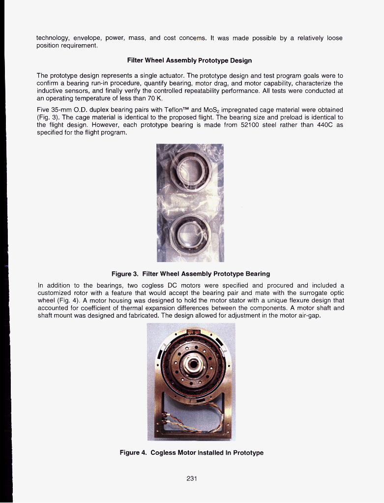
In addition to the bearings, two cogless DC motors were specified and procured and included a customized rotor with a feature that would accept the bearing pair and mate with the surrogate optic wheel (Fig. 4). A motor housing was designed to hold the motor stator with a unique flexure design that accounted for coefficient of thermal expansion differences between the components. A motor shaft and shaft mount was designed and fabricated. The design allowed for adjustment in the motor air-gap.
Figure 4. Cogless Motor Installed In Prototype
231

A set of inductive sensors were obtained (Fig. 5). The surrogate optic wheel was designed to provide 15- degree differential ramp targets. The sensor array and sensor track were integrated with the prototype design.
J
Figure 5. Inductive Sensors
Prototype Test Configuration
In parallel with the design and fabrication of the Filter Wheel assembly prototype, the team designed the necessary setup to test the assembly at 35 K. After selecting a cryogenic test chamber, the team specified the required test equipment. In addition, the team designed the appropriate tooling that would adequately hold the prototype during testing. In order to test the bearing and motor drag, a fixture was designed to hold the prototype within the cryo-chamber, while an external motor and encoder spun the rotor and wheel through a ferrofluidic feedthrough. A vacuum rated torque meter was coupled to the feedthrough inside the chamber to measure torque as close to the prototype as feasible.
Figure 4. Prototype Bearing Cold Test Configuration
232

Bearing Run-in and Cryogenic Drag Test Results
Bearing drag was the first performance characteristic tested. Each bearing was run-in at an ambient operating environment using a run-in test fixture. A ground support equipment (GSE) motor was used to rotate the motor at 40 RPMs for 200 revolutions in one direction then 200 revolutions in the opposite direction. A torque measurement at 1 RPM followed each sequence of 200 revolutions. A total of 10,000 revolutions were accomplished over a period of approximately four hours. Torque telemetry was continuously obtained by an in-line torque transducer. Post-test inspection and tests indicate that an average of 40 to 50 angstroms of Teflon lubrication was successfully transferred to the balls and races.
The bearing was then assembled onto the prototype shaft and installed into the cryo-chamber to test bearing drag at temperature. A bearing resistive torque of 5.4 mN-m (0.8 oz-in) was measured. This represents an increase of only 3.2 mN-m from the 2.2 mN-m tested at ambient.
While motor and bearing tests continued, additional bearings were run-in using the same 10,000 revolution procedure. These bearings were then inspected and characterized. Periodic inspection and photography indicates that at 20,000 revolutions, the bearing was in “as-new” condition both in terms of torque and physical condition (Fig. 5).
I
Figure 5. Prototype Bearing Post-Test inspection (20,110 revolutions)
It was determined that a bearing with a measured torque in excess of 21 mN-m (3.0 oz-in) was no longer functioning properly. The torque was irregular, and it was accompanied by an audible protest or squeak. A bearing end-of-life torque limit of 14 mN-m (2 oz-in) was established using the “Knee” of the ambient torque/life curve and allowing for measurement uncertainty. This is viewed as a very conservative limit.
Motor and Bearing Tests
After the bearing run-in tests were completed, the motor stator was assembled into the prototype housing for motor and bearing tests at temperature (Fig. 6). The same thermal vacuum test setup was used. A motor and bearing resistive torque of 9.6 mN-m was measured at temperature. This represents an increase of 4.2 mN-m over the bearing drag test.
233

Figure 6. Prototype Bearing, Motor, and Sensor Cryo-Test Configuration
The test configuration used to test motor and bearing drag also allowed for the measurement of the motor torque constant. By spinning the assembly at 50 RPM with the GSE motor and measuring the peak back emf voltage, the motor torque constant was determined to be 11 50 mN-m/A. Through both ambient and cry0 test runs, it was also shown that the torque constant was largely insensitive to the temperature and vacuum change.
Motor phase resistance dropped from 82 ohms to 2.2 ohms at temperature. This measurement was done with a simple two wire ohm meter in the prototype efforts, and the measurement includes all the GSE wire-some of it still at ambient temperatures. The flight testing will use a four-wire measurement to eliminate this measurement error. Using 2.2 ohms in the power calculation is considered conservative.
All mechanical connections to the test shaft were removed, and the assembly was tested cold under its own power. At each of the twelve positions, breakaway current was determined to be less than 10 mA. The motor was commanded to take 7 steps at a commanded current level. The motor was reset to pull it back to the motor zero position, and the commanded current level was increased. The process was repeated. Motion occurred prior to reaching a 10 mA command (Fig. 7).
A prototype control board was designed and built. Two power amplifiers (with current control) are used to generate commandable current. Since the net current into the node of a wye-wound motor is zero,-the third phase is generated as a difference between the first two. The electrical cycle was divided into steps using a 12-bit controller effectively giving the ability to micro-step. The motor is driven open-loop 30- degrees (4096 micro-steps) from one position to another. Once in the approximate position, the closed loop mode is activated, and the position sensors are used to “micro-step” to a final optic position. The position signal is differentiated and used in a damping circuit while in the closed loop mode. The result is a nicely damped response. The control loop can be used to drive to any value in the position signal, but the sensor ramp has been designed (and aligned) such that each optic position is nominally represented by a zero according to the position signal.
234

Figure 7. Breakaway Current Tests
Position Control Tests
A 17-bit encoder was connected to the test shaft of the prototype in order to obtain position data (Fig. 8). The sensor track design results in 12 zero-voltage position signals and two higher voltage reference signals in a single revolution of the wheel. The sensor track was aligned to the motor zero during assembly. These data were used to obtain a voltage level of 0.09 V that corresponds to the 0.310 mm position requirement.
Figure 8. Typical Voltage Response of Position Signal
Control scripts were written to command the motor from position to position switching back and forth from open loop to closed loop modes of operation just as proposed for flight (Fig. 9). A reset was used to pull the motor to the closest motor zero position. Open loop moves were accomplished by commanding a speed, a current, and a number of steps (4096). The scripts then closed the position loop and
235

commanded the error to zero. Finally, the motor current was ramped to zero. The whole process was repeated to accomplish 360 degree rotations. Closed-loop error was found to be acceptable at approximately 0.09 mm. However, the results indicate an unacceptable position error “spring-back effect when the holding current is removed. This error is illustrated by the nearly 0.5 V motion near the end of each position hold.
Figure 9. Nominal Rotation of Wheel to Twelve Positions
Dither and Check Routine
Through a series of build-up and breakdown tests of the prototype, it was determined that the powered-off position error is the result of both the bearing and the motor. The bearings are large (for a precision instrument bearing), and they have an outer-land riding cage. It is believed that this cage tends to store some windup energy when in motion. In addition, the DC motor appears to have a restoring energy. Additional tests are planned that will help verify the root cause of the motor restoring forces.
It has been shown that increased friction levels reduce the powered-off position error. This is good news as this means that this particular position error will not get worse at the end of bearing life. It also provides a possible solution to the problem. After much deliberation, it was determined that introducing another source of debris into our optic system was not advisable.
A common method for improving position results is to dither back and forth about the final position. This tends to relieve friction terms, and it has been shown to dramatically improve final positions of the prototype (Fig. 10). The motor is controlled past the intended final position by 1.4 degrees. This excursion is based on the ball-to-cage pocket clearance and is intended to specifically address bearing cage windup. The wheel is then commanded by half that excursion to the opposite side of the final position. The distance is halved again. The final “dither” is not always possible to see in the position signal. However, this approach does not guarantee a final position.
236

Figure 10. Results Showing Dither Improvements
The proposed final solution is to dither and check three times before applying a powered-on hold. If the powered off position error is unacceptable, then a dither is commanded. If the position error is still unacceptable after dithering 3 times, then the system leaves power on (8 mA) (Fig. 11).
. . .. i dither
Figure 11 : Typical Dither Details
237

Conclusions
A calculated torque margin of 1.8 is now supported by engineering test results. A motor torque constant of 1150 mN-m/amp was measured at ambient and operating temperature and meets the specified minimum of 1100 mN-mlA. A motor drag torque of 4.7 mN-m was measured and is less than the specified maximum of 5.3 mN-m. Cold bearing testing of the W A prototype successfully characterized the bearings at various cold temperatures and established an end-of-life bearing torque limit of 14 mN-m (2 oz-in). Further life tests are planned.
A measured motor phase resistance of 2.2 ohms results in an estimated peak power consumption of 89 mW and an average power consumption of 0.44 mW when operated at its maximum duty cycle.
Motor control and current margin have been demonstrated at a temperature of 20 K. A powered-on closed loop control error of 0.09 mm was measured at operational temperatures. A breakaway current of less than 10 mA was measured.
Acknowledgements
Development of the NlRCam instrument at the Lockheed Martin Advanced Technology Center is performed under contract to and teamed with the University of Arizona’s Steward Observatory. The University of Arizona in turn is under contract to the JWST Project at the NASA Goddard Space Flight Center.
A great deal of team work was necessary to accomplish these tests. Tom Welsh, Bud Swihart, and Richard Bnrner played critical roles in getting the hardware to the proper test temperature. Their efforts and dedication are greatly appreciated.
References
[l] Gould S.G., E.W. Roberts, “THE IN-VACUO TORQUE PERFORMANCE OF DRY-LUBRICATED BALL BEARINGS AT CRYOGENIC TEMPERATURES,” 23rd Aerospace Mechanism Symposium, 1989.
238