
Development of Upper-Extremity IMU to OpenSim Data ...
10
1. 2. 3. 4. Development of Upper-Extremity IMU to OpenSim Data Conversion Method Team Members Elizabeth Alderman Kevin Brenner Caitlin Hogan Time Line Convert IMU–> OpenSim Code to Upper Body Applications 11 May 2018 Collect/verify initial IMU data 16 May 2018 Write up procedure for calibration method, IMU placement, and relevant motions for MOCAP or Calibration Method experiments 21 May 2018 Gather MOCAP or additional IMU Data for Accuracy Evaluation 25 May 2018 Present findings 31 May 2018 Provide final write-up including any necessary procedural documentation 05 Jun 2018 Project Video Background and Motivation Two common approaches for experimentally tracking motion are Visual Motion Capture (MOCAP) and Inertial Measurement Units (IMUs). Using MOCAP, markers on the subject are visually tracked and the resulting positions can be differentiated into joint angle velocities and accelerations. Using IMUs, point accelerations, as well as angular velocity and magnetic orientation, are collected and can be integrated into joint kinematics. While MOCAP is widely used, its applications are restricted to lab settings and are costly to implement. In contrast, an IMU's relatively small size and use of stand-alone sensors makes the technology ideal for 'in the wild" motion capture. Many industries would benefit from the use of IMU technology, including rehabilitation medicine, sports performance, robotics, and entertainment. Unfortunately, there is no widespread consensus on IMU placement or calibration, leading to much confusion in the field. In order to accurately capture joint kinematics from the IMU data, calibration must be used to map the sensors to the anatomical segments and the placement of the IMUs must be known. The benefits and drawbacks of different calibration methods and IMU placements is a widely researched topic. Bou investigated the accuracy of three different IMU calibration methods to relate sensors to segments. This paper served as the basis for our vier 2015 investigation; however, we feel that there are still additional concerns to address. A large drawback of the Bouvier study is the reliance on the XSens algorithm to obtain the motion kinematics. This creates a black box in the experimental process, preventing the researcher from understanding what assumptions are being made and blocks the user from adjusting the equations to fit specific applications. While this research into calibration methods is valuable, the 'black box' brings many unknowns into the picture, making it impossible to fully understand why, and even if, one calibration method is better than another. It also greatly limits the types of calibration that can be performed and effectively locks the IMU placements to match those the black box expects, unnecessarily limiting the potential uses for IMUs. The goal of this project is to develop a transparent, open source algorithm which will replace the 'black box' algorithms used in previous studies. The algorithm takes experimental upper extremity IMU data and performs the necessary calibrations and modifications to transform it into an OpenSim compatible format. From there the data will be mapped to a model to perform kinematic analysis. Practical Goal and Related Questions Practical Goal: Develop a program to import Upper Extremity XSens IMU data into OpenSim for kinematic analysis. Related Questions: How does different "ground" IMU placement affect IK accuracy? How does "ground" IMU tilt affect IK accuracy? Of the available upper extremity models, which provides the most accurate simulation from the IMU data and why? Can answers to the above questions inform a more accurate IMU placement or calibration method? If so, what are the recommended IMU placements and calibration methods? Methods 1. Data Collection Method 1.1 IMU Placement
Transcript of Development of Upper-Extremity IMU to OpenSim Data ...

1. 2. 3. 4.
Development of Upper-Extremity IMU to OpenSim Data Conversion MethodTeam Members
Elizabeth AldermanKevin BrennerCaitlin Hogan
Time Line
Convert IMU–> OpenSim Code to Upper Body Applications 11 May 2018
Collect/verify initial IMU data 16 May 2018
Write up procedure for calibration method, IMU placement, and relevant motions for MOCAP or Calibration Method experiments 21 May 2018
Gather MOCAP or additional IMU Data for Accuracy Evaluation 25 May 2018
Present findings 31 May 2018
Provide final write-up including any necessary procedural documentation 05 Jun 2018
Project Video
Background and Motivation
Two common approaches for experimentally tracking motion are Visual Motion Capture (MOCAP) and Inertial Measurement Units (IMUs). Using MOCAP, markers on the subject are visually tracked and the resulting positions can be differentiated into joint angle velocities and accelerations. Using IMUs, point accelerations, as well as angular velocity and magnetic orientation, are collected and can be integrated into joint kinematics. While MOCAP is widely used, its applications are restricted to lab settings and are costly to implement. In contrast, an IMU's relatively small size and use of stand-alone sensors makes the technology ideal for 'in the wild" motion capture. Many industries would benefit from the use of IMU technology, including rehabilitation medicine, sports performance, robotics, and entertainment. Unfortunately, there is no widespread consensus on IMU placement or calibration, leading to much confusion in the field.
In order to accurately capture joint kinematics from the IMU data, calibration must be used to map the sensors to the anatomical segments and the placement of the IMUs must be known. The benefits and drawbacks of different calibration methods and IMU placements is a widely researched topic. Bou
investigated the accuracy of three different IMU calibration methods to relate sensors to segments. This paper served as the basis for our vier 2015investigation; however, we feel that there are still additional concerns to address. A large drawback of the Bouvier study is the reliance on the XSens algorithm to obtain the motion kinematics. This creates a black box in the experimental process, preventing the researcher from understanding what assumptions are being made and blocks the user from adjusting the equations to fit specific applications. While this research into calibration methods is valuable, the 'black box' brings many unknowns into the picture, making it impossible to fully understand why, and even if, one calibration method is better than another. It also greatly limits the types of calibration that can be performed and effectively locks the IMU placements to match those the black box expects, unnecessarily limiting the potential uses for IMUs.
The goal of this project is to develop a transparent, open source algorithm which will replace the 'black box' algorithms used in previous studies. The algorithm takes experimental upper extremity IMU data and performs the necessary calibrations and modifications to transform it into an OpenSim compatible format. From there the data will be mapped to a model to perform kinematic analysis.
Practical Goal and Related Questions
Practical Goal: Develop a program to import Upper Extremity XSens IMU data into OpenSim for kinematic analysis.
Related Questions:
How does different "ground" IMU placement affect IK accuracy?How does "ground" IMU tilt affect IK accuracy?Of the available upper extremity models, which provides the most accurate simulation from the IMU data and why?Can answers to the above questions inform a more accurate IMU placement or calibration method? If so, what are the recommended IMU placements and calibration methods?
Methods
1. Data Collection Method
1.1 IMU Placement

Data was collected using three IMUs placed on the right arm and three on the torso as shown in the figure below. The IMUs on the arm were located on the hand, mid-forearm, and mid-upper arm. The arm IMUs were aligned in the plane of the arm to the best visual estimate of the underlying bone's angle, placed on the lateral side of the arm. The provided straps were wrapped securely around the subject's upper forearm and proximal upper arm. Provided hand covers were used for IMU attachment at the hand.
The IMUs on the torso served as the 'ground' IMU when processing the data. Due to the importance of the ground IMU position on the results, three different ground IMU placements were evaluated. In order to test multiple ground placements on the same motion, data was collected with all three torso IMUs active. The data was then processed by selecting only one torso IMU to be the ground IMU. The data from the other torso IMUs would not be accounted for in that simulation. This was repeated for each IMU on the torso. The evaluated ground IMU placements were the stomach, lower back, and upper back. The stomach and lower back IMU were secured with a strap wrapped around the subject's waist. The upper back IMU was placed on a strap wrapped around the subject's chest at the largest circumferential point.
1.2 Motions Captured
Three motions were captured for kinematic analysis: elbow flexion, shoulder flexion, and wrist supination. The motions were chosen from the Fugl-Meyer Assessment, a method used for motor recovery evaluation after stroke. These motions were chosen because they effectively isolated the three joints of interest. Additionally, these motions reflect those which patients would perform if IMUs were to be used for quantitative Fugl-Meyer assessment. GIFs of the motions being performed can be seen in the videos below.

2. Models Evaluated
Two OpenSim models were evaluated for accuracy with the developed algorithm. MoBL-ARMS Dynamic Upper Limb is an upper limb model created by Saul et al. ( ). This model has 7 degrees of freedom and models all muscles in the right limb. https://simtk.org/frs/?group_id=657The second model evaluated was developed by Seth et al. ( ) It models the Scapulothoracic Joint https://simtk.org/projects/scapulothoracicand has17 degrees of freedom, although no muscles are included.
2.1 Initial Pose of the Model
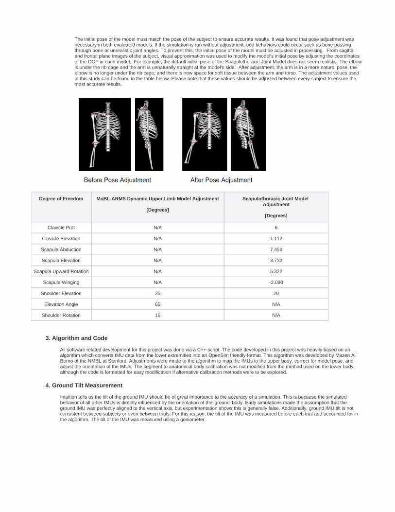
The initial pose of the model must match the pose of the subject to ensure accurate results. It was found that pose adjustment was necessary in both evaluated models. If the simulation is run without adjustment, odd behaviors could occur such as bone passing through bone or unrealistic joint angles. To prevent this, the initial pose of the model must be adjusted in processing. From sagittal and frontal plane images of the subject, visual approximation was used to modify the model's initial pose by adjusting the coordinates of the DOF in each model. For example, the default initial pose of the Scapulothoracic Joint Model does not seem realistic. The elbow is under the rib cage and the arm is unnaturally straight at the model's side. After adjustment, the arm is in a more natural pose, the elbow is no longer under the rib cage, and there is now space for soft tissue between the arm and torso. The adjustment values used in this study can be found in the table below. Please note that these values should be adjusted between every subject to ensure the most accurate results.
Degree of Freedom MoBL-ARMS Dynamic Upper Limb Model Adjustment
[ ]Degrees
Scapulothoracic Joint Model Adjustment
[ ]Degrees
Clavicle Prot N/A 6
Clavicle Elevation N/A 1.112
Scapula Abduction N/A 7.456
Scapula Elevation N/A 3.732
Scapula Upward Rotation N/A 5.322
Scapula Winging N/A -2.080
Shoulder Elevation 25 20
Elevation Angle 65 N/A
Shoulder Rotation 15 N/A
3. Algorithm and Code
All software related development for this project was done via a C++ script. The code developed in this project was heavily based on an algorithm which converts IMU data from the lower extremities into an OpenSim friendly format. This algorithm was developed by Mazen Al Borno of the NMBL at Stanford. Adjustments were made to the algorithm to map the IMUs to the upper body, correct for model pose, and adjust the orientation of the IMUs. The segment to anatomical body calibration was not modified from the method used on the lower body, although the code is formatted for easy modification if alternative calibration methods were to be explored.
4. Ground Tilt Measurement
Intuition tells us the tilt of the ground IMU should be of great importance to the accuracy of a simulation. This is because the simulated behavior of all other IMUs is directly influenced by the orientation of the 'ground' body. Early simulations made the assumption that the ground IMU was perfectly aligned to the vertical axis, but experimentation shows this is generally false. Additionally, ground IMU tilt is not consistent between subjects or even between trials. For this reason, the tilt of the IMU was measured before each trial and accounted for in the algorithm. The tilt of the IMU was measured using a goniometer.

Results and Discussion
Due to time limitations, only elbow joint angle as a result of elbow flexion was evaluated as part of this project. All relevant data files can be found below.
In the following plots, Ajay's Model refers to the Scapulothoracic Joint Model, and Kate's Model refers to the MoBL-ARMS Dynamic Upper Limb Model.
1.Tilt Adjustment
The plots below validate the statement that the tilt of the ground IMU has a significant impact on the accuracy of the results. The plots on labeled "Without Tilt Adjustment" show the elbow flexion without any tilt adjustment, effectively assuming the ground IMU is perfectly vertical throughout the motion. The plots labeled "With Tilt Adjustment" account for the initial tilt of the ground IMU, although they do not capture change in tilt over time. During the measured motion, the subject achieved elbow flexion to approximately 90 degrees each repetition. Both the Scapulothoracic Joint Model and the MoBL-ARMS Dynamic Upper Limb Model saw an improvement in accuracy when the measured tilt was applied. This improvement was most significant on the upper back IMU. The effect on the lower back ground IMU was small but not negligible since the simulated elbow flexion did get closer to 90 degrees after adjustment. The adjustment to the stomach IMU had the unexpected effect of decreasing the accuracy of the results. This may be due to the fact that the stomach IMU is mounted on soft tissue, so the tilt is more susceptible to soft tissue motion.


2.Ground IMU Comparison
The plots below illustrate that the most accurate of the tested ground IMU placements is on the lower back. Please note that these plots illustrate elbow flexion after the tilt adjustment has been implemented. As can be seen in both models, the ground IMU on the lower back increases the calculated elbow flexion, bringing it closer to the observed 90 degrees. The ground IMU on the upper back provides the next most accurate placement, although the Scapulothoracic Joint Model is still far more accurate using the ground IMU on the lower back. This placement's superior accuracy is likely tied to a number of factors. Both back IMUs were placed near the spine, on a relatively bony surface. In contrast, the stomach IMU was on loose skin, likely leading a large source of error. Additionally, the tilt of the lower back IMU was the most straight forward to measure using a goniometer and likely changes less than the upper back tilt throughout the motion.
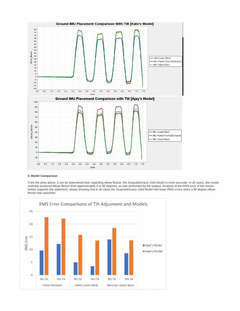
3. Model Comparison
From the plots above, it can be determined that, regarding elbow flexion, the Scapulothoracic Joint Model is more accurate. In all cases, this model routinely produced elbow flexion from approximately 0 to 90 degrees, as was performed by the subject. Analysis of the RMS error of the results further supports this statement, clearly showing that in all cases the Scapulothoracic Joint Model had lower RMS errors when a 90 degree elbow flexion was assumed.

1. 2. 3.
4.
The motion, as performed by the subject, and the resulting OpenSim visuals can be seen below. The leftmost GIF shows the action as performed by the subject. The second GIF from the left illustrates the importance of initial pose adjustment, as discussed previously. In that image, the elbow can be seen to intersect the rib cage, and the shoulder twists unnaturally. The GIF third from the left is the resulting motion on the MoBL-ARMS Dynamic Upper Limb Model after pose adjustment. The rightmost GIF shows the motion on the Scapulothoracic Joint Model after pose adjustment. Comparing the two rightmost GIFs, it can be seen that the Scapulothoracic Joint Model does flex the elbow more than the MoBL-ARMS Dynamic Upper Limb Model. This difference is likely due to the increased DOF from the MoBL-ARMS Dynamic Upper Limb Model to the Scapulothoracic Joint Model, 7 to17 respectively. Additionally, the modeling of the Scapulothoracic Joint means the right most model is more representative of human physiology, and logically produces a more representative result.
4. Limitations
A main limitation of this study is the use of visual approximation to set the subject initial pose and initial tilt of the ground IMU, and to determine the true flexion of the elbow as performed by the subject. Although all this was done with much scrutiny, using alternative methods to remove the need to visually approximate would greatly increase the rigor of this study. A further limitation is the inability to perfectly place the IMUs to match the marker location in each OpenSim model. These inconsistencies in the placement of the IMUs versus the corresponding marker location may lead to tracking errors throughout the motion.
Conclusions
Placing the Ground IMU on the lower back near the spine yields the most accurate results.Correcting for the tilt of the ground IMU helps improve the accuracy of the simulation only if the ground IMU is mounted to a bony surface. The MoBL-ARMS Dynamic Upper Limb is less accurate than the Scapulothoracic Joint Model. This is likely because the Scapulothoracic Joint Model is more representative of a human arm and shoulder.The above answers do inform IMU placement of the ground IMU, but have little impact on either the calibration method or arm IMU placements.
While we were able to answer the main questions posed, future work is needed to determine appropriate IMU placement and calibration to accurately capture upper limb kinematics.
Future Work
There are a number of areas for future work and method improvements. Of the major challenges faced, the inability to test with a ground IMU on the sternum leaves major unresolved question. Both OpenSim models have the axes of rotation centered on the ground body at approximately the sternum. From that, it is reasonable to hypothesize that a ground IMU placed on the sternum will yield more accurate results than one placed elsewhere on the torso. Unfortunately we were unable to securely mount an IMU to this location, thus we were not able to test the sternum as a possible ground IMU location. Future studies should repeat the outlined method with an IMU on the sternum and another on the lower back to compare the ground IMU placements.
The method outlined previously required the researcher to measure the ground IMU tilt visually using a goniometer before each trial. This method, while accurate enough for rough trials, is prone to errors and does not realistically capture the tilt of the ground IMU throughout the motion. To fully and accurately account for tilt of the ground IMU, future experiments should use the accelerometers in the IMUs to calculate tilt at all time steps through the motion. This tilt should then be dynamically updated while the data is being processed.

1.
2.
3.
4.
5.
Although the Scapulothoracic Joint Model yielded more accurate results, there are still some motion anomalies that need to be addressed. As can be seen in GIF below, the scapular dynamics behave abnormally at multiple points. The exact cause of this is unknown but potential fixes including modeling of the muscles and re-evaluation of contact forces and joint limits. The method outlined here should be repeated on any new or updated upper extremity models to evaluate both the model and the algorithm's accuracy.
The algorithm and corresponding C++ script was developed for this very specific application. The code has been heavily commented and is relatively easy to modify, but the user experience could be greatly improved if a GUI was created. Many of the problems faced throughout this project were minor bugs in the code which could easily be avoided by implementing a GUI. Additionally, a GUI would allow for quick repetition of trials or modifications to account for multiple subjects and IMU placements. Features which would be beneficial in the GUI include the ability to adjust the initial pose of the model, select the desired IMU data files, and adjust the orientation of the ground IMU depending on its placement.
Further validation is necessary before this algorithm can be fully accepted as a viable alternative to implementing IMU motion capture. Trials should be performed using MOCAP or alternative image processing techniques to allow for quantitative measurements of the accuracy of the method. This method should also be compared to the internal XSens algorithm in order to gauge the accuracy of both computations. Furthermore, the outlined method should be repeated for the wrist and shoulder joints, ideally evaluating all degrees of freedom for both joints.
Next steps in this research include evaluating different calibration methods and IMU placements. As done by Bouvier (2015), the three most common calibration methods should be evaluated: Static, Technical, and Functional. Alternative calibration methods could be developed and tested as well. Ideally, this data processing method could be used to develop more flexible calibration methods which can be used in scenarios where the subject cannot obtain the calibration pose. Other uses of this OpenSim based method include research into the ideal placement of IMUs for capturing specific motions. Questions such as, "What is the minimum number of IMUs needed to capture a motion?", can be answered. Overall, this OpenSim based IMU data processing method provides a transparent means to find joint kinematics from IMU data. This will allow for more rigorous research to be performed and will lead to more widespread use of IMUs in motion capture.
Acknowledgements
We would like to thank Mazen Al Borno, Ajay Seth, Tom Uchida, Scott Delp, and the entire ME 485 Teaching Team for their support throughout this project.
References
Bouvier, B., Duprey, S., Claudon, L., Dumas, R., Savescu, A., (2015) Upper Limb Kinematics Using Inertial and Magnetic Sensors: Comparison of Sensor-to-Segment Calibrations. Sensors 2015,18813-18833.Deakin, A., Hill, H., Pomeroy, V., (2003). Rough Guide to the Fugl-Meyer Assessment: Upper Limb Section. Physiotherapy. Volume 89, Issue 12, 751–763.Gladstone, D., Danells, C., Black, S., (2002). The Fugl-Meyer Assessment of Motor Recovery after Stroke: A Critical Review of Its Measurement Properties. Neurorehabilitation and Neural Repair. Vol 16, Issue 3.Saul KR, Hu X, Goehler CM, Daly M, Vidt ME, Velisar A, Murray WM. (2015). Benchmarking of dynamic simulation predictions in two software platforms using an upper limb musculoskeletal model. Computer Methods in Biomechanics and Biomedical Engineering. 2015; 18:1445-58. 10.1080/10255842.2014.916698.Seth A, Matias R, Veloso AP and Delp SL. (2015). A biomechanical model of the scapulothoracic joint to accurately capture scapular kinematics during shoulder movements. PLOS ONE.
Home: BIOE-ME 485 Spring 2018