
Development of the Primary Mirror Segment Support ...eric.ericandlucie.com/Resume/Publications/TMT...
19
SPIE Paper 6273-45 1 of 19 Proc. SPIE, Vol. 6273, pp. 379-397, Optomechanical Technologies for Astronomy, Eli Atad-Ettedgui, Joseph Antebi, and Dietrich Lemke, Eds, July 2006. Presented at the SPIE Astronomical Telescopes and Instrumentation Symposium, Orlando, Florida, May 24-31, 2006. Development of the Primary Mirror Segment Support Assemblies for the Thirty Meter Telescope Eric Ponslet *a , Dan Blanco b , Myung Cho b , Terry Mast c , Jerry Nelson c , RJ Ponchione a , Mark Sirota d , Vince Stephens a , Larry Stepp d , Alan Tubb a , Eric C. Williams a a HYTEC, Inc., 110 Eastgate Drive, Los Alamos, NM, USA 87544; b NOAO, 950 N. Cherry Avenue, Tucson, AZ, USA 85719; c Center for Adaptive Optics, University of California, Santa Cruz, USA 95064; d TMT Project, 2632 East Washington Blvd, Pasadena, CA, USA 91107 ABSTRACT This paper describes the studies performed to establish a baseline conceptual design of the Segment Support Assembly (SSA) for the Thirty Meter Telescope (TMT) primary mirror. The SSA uses a combination of mechanical whiffletrees for axial support, a central diaphragm for lateral support, and a whiffletree-based remote-controlled warping harness for surface figure corrections. Axial support whiffletrees are numerically optimized to minimize the resulting gravity- induced deformation. Although a classical central diaphragm solution was eventually adopted, several lateral support concepts are considered. Warping harness systems are analyzed and optimized for their effectiveness at correcting second and third order optical aberrations. Thermal deformations of the optical surface are systematically analyzed using finite element analysis. Worst-case performance of the complete system as a result of gravity loading and temperature variations is analyzed as a function of zenith angle using an integrated finite element model. Keywords: TMT, segment, mirror, support, whiffletree, warping-harness, active, optics, optimization, FEA 1. INTRODUCTION The Thirty Mirror Telescope (TMT 1 ) project, a partnership between ACURA, AURA, Caltech, and the University of California, is currently planning a thirty meter diameter optical-infrared, ground based telescope. The telescope will be used for research in astronomy at near-ultraviolet, visible and near infra-red wavelengths. The optical design is an Aplanatic-Gregorian with a 30-meter diameter, f/1, segmented primary mirror; a 3.6-meter diameter, concave secondary mirror; and a flat tertiary mirror. These will deliver an f/15 beam to the adaptive optic systems and science instruments located on two Nasmyth platforms. During observation, the telescope structure moves 360 degrees in azimuth and 0-65 degrees in zenith angle. A space frame mirror cell carries the segmented primary mirror. The segmented Primary Mirror (PM) will be comprised of 738 independent, Low Expansion (LE) glass segments, separated by 2 mm gaps. Each segment is hexagonal, cut from an aspherical meniscus, with a 0.6 meter nominal side length, and a thickness of 40 mm. To achieve the required surface accuracy and stability (less than 10 nm surface RMS figure error from support-induced deformations), each segment will be supported by a multi-point, passive, near- kinematic system of levers and flexures, actively controlled in piston, tip and tilt by a set of three linear actuators, and figure-controlled by an automated warping harness. The TMT segment support design is largely based on technologies developed for other segmented mirrors. It is an evolution of the Keck 2,3 designs, with some features adopted from the Southern African Large Telescope (SALT 4,5,6,7 ), which was recently inaugurated. Even though large segmented telescopes are only about 20 years old, the technological approaches to segment support are relatively well established. Almost every segmented telescope project since Keck has used mechanical whiffletrees for axial support, and a central diaphragm lateral support. In contrast with earlier segmented telescopes of the 10-meter class such as Keck, the much larger size of the TMT primary mirror will result in increased gravity-induced deflections of the PM cell, requiring larger actuator strokes to maintain segment positioning. The TMT primary mirror segments will also be thinner than previous large telescopes, which makes control of gravity-induced deflections a more difficult problem. These characteristics drove us to adopt a * [email protected]; phone 1 505 661-3000, ext. 15; fax 1 505 662-5179; www.hytecinc.com
Transcript of Development of the Primary Mirror Segment Support ...eric.ericandlucie.com/Resume/Publications/TMT...

SPIE Paper 6273-45 1 of 19 Proc. SPIE, Vol. 6273, pp. 379-397, Optomechanical Technologies for Astronomy, Eli Atad-Ettedgui, Joseph Antebi, and Dietrich Lemke, Eds, July 2006. Presented at the SPIE Astronomical Telescopes and Instrumentation Symposium, Orlando, Florida, May 24-31, 2006.
Development of the Primary Mirror Segment Support
Assemblies for the Thirty Meter Telescope
Eric Ponslet*a, Dan Blanco
b, Myung Cho
b, Terry Mast
c, Jerry Nelson
c, RJ Ponchione
a, Mark Sirota
d,
Vince Stephensa, Larry Stepp
d, Alan Tubb
a, Eric C. Williams
a
aHYTEC, Inc., 110 Eastgate Drive, Los Alamos, NM, USA 87544;
bNOAO, 950 N. Cherry Avenue, Tucson, AZ, USA 85719;
cCenter for Adaptive Optics, University of California, Santa Cruz, USA 95064;
dTMT Project, 2632 East Washington Blvd, Pasadena, CA, USA 91107
ABSTRACT
This paper describes the studies performed to establish a baseline conceptual design of the Segment Support Assembly
(SSA) for the Thirty Meter Telescope (TMT) primary mirror. The SSA uses a combination of mechanical whiffletrees
for axial support, a central diaphragm for lateral support, and a whiffletree-based remote-controlled warping harness for
surface figure corrections. Axial support whiffletrees are numerically optimized to minimize the resulting gravity-
induced deformation. Although a classical central diaphragm solution was eventually adopted, several lateral support
concepts are considered. Warping harness systems are analyzed and optimized for their effectiveness at correcting
second and third order optical aberrations. Thermal deformations of the optical surface are systematically analyzed
using finite element analysis. Worst-case performance of the complete system as a result of gravity loading and
temperature variations is analyzed as a function of zenith angle using an integrated finite element model.
Keywords: TMT, segment, mirror, support, whiffletree, warping-harness, active, optics, optimization, FEA
1. INTRODUCTION
The Thirty Mirror Telescope (TMT1) project, a partnership between ACURA, AURA, Caltech, and the University of
California, is currently planning a thirty meter diameter optical-infrared, ground based telescope. The telescope will be
used for research in astronomy at near-ultraviolet, visible and near infra-red wavelengths. The optical design is an
Aplanatic-Gregorian with a 30-meter diameter, f/1, segmented primary mirror; a 3.6-meter diameter, concave secondary
mirror; and a flat tertiary mirror. These will deliver an f/15 beam to the adaptive optic systems and science instruments
located on two Nasmyth platforms. During observation, the telescope structure moves 360 degrees in azimuth and 0-65
degrees in zenith angle. A space frame mirror cell carries the segmented primary mirror.
The segmented Primary Mirror (PM) will be comprised of 738 independent, Low Expansion (LE) glass segments,
separated by 2 mm gaps. Each segment is hexagonal, cut from an aspherical meniscus, with a 0.6 meter nominal side
length, and a thickness of 40 mm. To achieve the required surface accuracy and stability (less than 10 nm surface RMS
figure error from support-induced deformations), each segment will be supported by a multi-point, passive, near-
kinematic system of levers and flexures, actively controlled in piston, tip and tilt by a set of three linear actuators, and
figure-controlled by an automated warping harness.
The TMT segment support design is largely based on technologies developed for other segmented mirrors. It is an
evolution of the Keck2,3 designs, with some features adopted from the Southern African Large Telescope (SALT
4,5,6,7),
which was recently inaugurated. Even though large segmented telescopes are only about 20 years old, the technological
approaches to segment support are relatively well established. Almost every segmented telescope project since Keck has
used mechanical whiffletrees for axial support, and a central diaphragm lateral support.
In contrast with earlier segmented telescopes of the 10-meter class such as Keck, the much larger size of the TMT
primary mirror will result in increased gravity-induced deflections of the PM cell, requiring larger actuator strokes to
maintain segment positioning. The TMT primary mirror segments will also be thinner than previous large telescopes,
which makes control of gravity-induced deflections a more difficult problem. These characteristics drove us to adopt a
* [email protected]; phone 1 505 661-3000, ext. 15; fax 1 505 662-5179; www.hytecinc.com

SPIE Paper 6273-45 2 of 19 Proc. SPIE, Vol. 6273, pp. 379-397, Optomechanical Technologies for Astronomy, Eli Atad-Ettedgui, Joseph Antebi, and Dietrich Lemke, Eds, July 2006. Presented at the SPIE Astronomical Telescopes and Instrumentation Symposium, Orlando, Florida, May 24-31, 2006.
moving frame support concept7 first introduced by the designers of the Southern African Large Telescope (SALT). In
this approach, an intermediate, stiff moving frame is used to isolate the segment from the relatively large flexure
reactions which result from the large actuator motions. The moving frame, guided by a separate set of flexures, absorbs
these loads.
Keck3 HET
8 SALT
7 GTC
9 LAMOST
10,11 TMT baseline
PM Error budget EE80 < 0.32 arcsec EE80 < 0.90 arcsec EE80 < 0.24 arcsec
Number of Segments
36 + 6 spares (Keck I or II, each)
91 + 3 spares 91 + 3 spares 36 + 6 spares 37
(Spherical Primary)
738 + 123 spares
Segment size (circumscribed Ø)
1.8 m 1.15 m 1.15 m 1.9 m 1.1 m 1.2 m
Segment thickness
Bending stiffness, (EI)
75 mm
(EI ~ 7)
52 mm
(EI ~ 2)
50 mm
(EI ~ 2)
80 mm
(EI ~ 8)
75 mm
(EI ~ 7)
40 mm
(EI ~ 1)
Axial support 36-pt whiffletree 9-pt whiffletree 9-pt whiffletree 36-pt whiffletree 18-pt whiffletree 27-pt whiffletree
Lateral support Central diaphragm Central diaphragm Central diaphragm Central diaphragm Central diaphragm Central diaphragm
Warping harness Manual, 30 DOF† None None Automated, 6 DOF None Automated, 18
DOF
Elevation Variable Fixed (55°) Fixed (55°) Variable Fixed (-25°) Variable
Actuation Direct Direct Moving frame Direct Direct Moving frame
Segment gaps 3 mm 6 to 19 mm 3 mm 6.5 mm 2 mm
Accommodation for segment geometry variations
Weights on segments
None (all segments identical)
None (all segments identical)
Weights on WT Customize WT joint locations
First light May 1993 (Keck I),
Oct. 1996 (Keck II)
December 1996 September 2005 Late 2006 (expected)
2007 (expected) 2014 (planned)
Table 1: Comparison of existing and planned primary mirror segments for large ground-based telescopes.
An automated warping harness with 18 actuators per segment will provide the ability to remotely alter the surface figure
of each segment as frequently as several times per night, if required, to correct for effects such as coating stresses,
figuring errors, lateral position errors, and through-the-thickness variations of the coefficient of thermal expansion of the
glass.
Finally, given the unprecedented number of segments in TMT (738 + 123 spares), cost control is a major consideration
in the design process. The target cost of TMT is less than half of the scaled-up Keck cost. This places very stringent
requirements on fabrication costs in every subsystem. In the case of the SSA, the relatively large number of replications
of an identical assembly gives us an opportunity to consider mass production approaches, which will help control costs.
2. SYSTEM OVERVIEW AND REQUIREMENTS
Each mirror segment will interface with the mirror cell (primary truss) through a Segment Support Assembly (SSA),
which will provide several functions:
• Support the segment in the axial (piston, tip, and tilt) and lateral (two in-plane directions and clocking) degrees
of freedom in a way that maintains segment position within the required accuracy and minimizes gravity-
induced distortions of the segment as the elevation angle changes.
• Maintain vibration mode frequencies above specified levels to minimize disturbances from external sources
such as wind & machinery.
• Accommodate a precision tip/tilt/piston position control capability, as provided by three precision linear
actuators and twelve edge-mounted displacement sensors per segment.
• Provide the ability to re-figure the segment in a controlled manner.
• Provide a means to accurately and permanently align each SSA during initial installation
• Provide a registration feature that allows removal and replacement of a segment with itself or a spare segment
with specified repeatability without realignment.
• Provide a means of decoupling a segment assembly from its base and lifting it out of the PM array.
† DOF (degree of freedom)
SPIE Paper 6273-45 3 of 19 Proc. SPIE, Vol. 6273, pp. 379-397, Optomechanical Technologies for Astronomy, Eli Atad-Ettedgui, Joseph Antebi, and Dietrich Lemke, Eds, July 2006. Presented at the SPIE Astronomical Telescopes and Instrumentation Symposium, Orlando, Florida, May 24-31, 2006.
• Provide a way to accommodate variable segment geometry with a single support system design.
• Protect the segment during any anticipated non-operating events such as shipping, handling, seismic, or similar.
2.1. Primary mirror segmentation
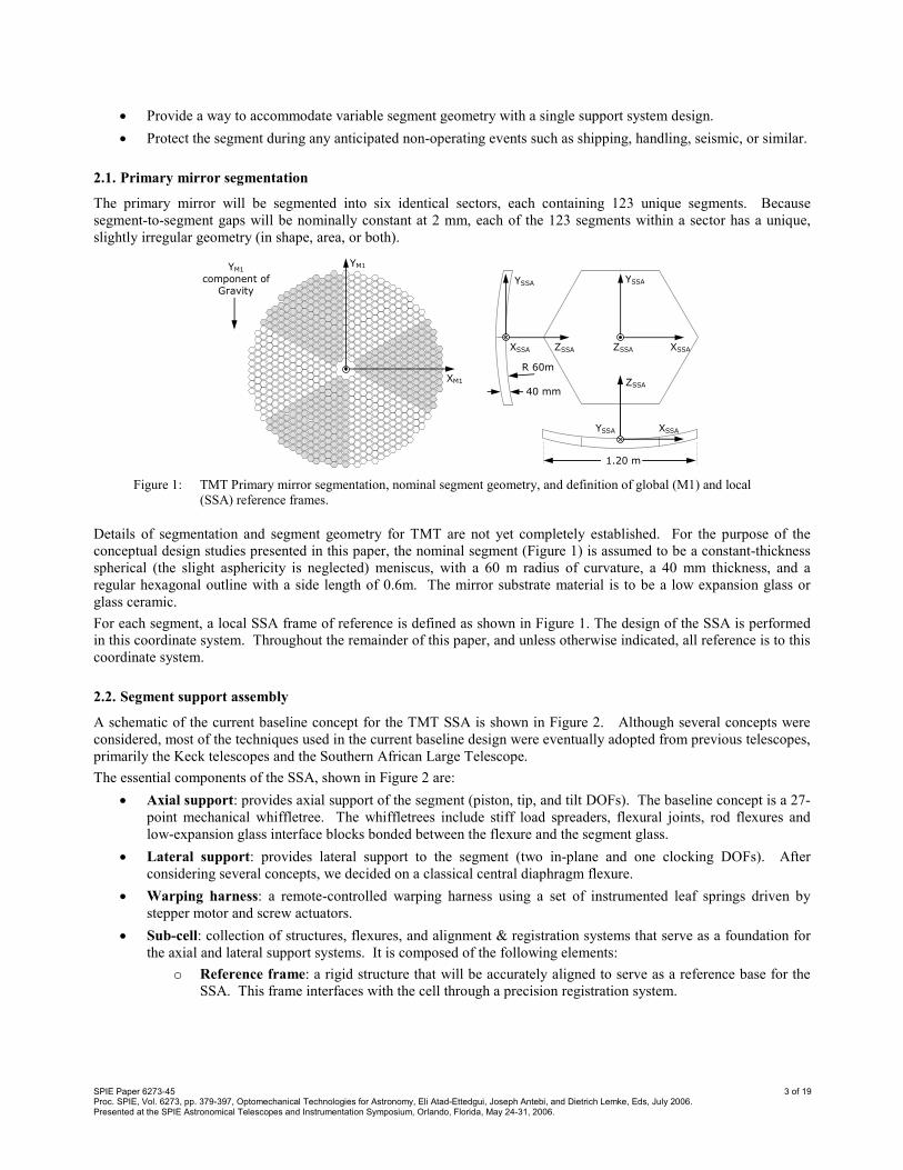
The primary mirror will be segmented into six identical sectors, each containing 123 unique segments. Because
segment-to-segment gaps will be nominally constant at 2 mm, each of the 123 segments within a sector has a unique,
slightly irregular geometry (in shape, area, or both).
XSSA
YSSA
ZSSA
YSSA
ZSSA
XSSA
ZSSA
YSSA
XSSA
1.20 m
40 mm
R 60m
YM1
XM1
YM1
component of
Gravity
Figure 1: TMT Primary mirror segmentation, nominal segment geometry, and definition of global (M1) and local
(SSA) reference frames.
Details of segmentation and segment geometry for TMT are not yet completely established. For the purpose of the
conceptual design studies presented in this paper, the nominal segment (Figure 1) is assumed to be a constant-thickness
spherical (the slight asphericity is neglected) meniscus, with a 60 m radius of curvature, a 40 mm thickness, and a
regular hexagonal outline with a side length of 0.6m. The mirror substrate material is to be a low expansion glass or
glass ceramic.
For each segment, a local SSA frame of reference is defined as shown in Figure 1. The design of the SSA is performed
in this coordinate system. Throughout the remainder of this paper, and unless otherwise indicated, all reference is to this
coordinate system.
2.2. Segment support assembly
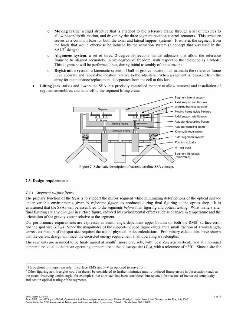
A schematic of the current baseline concept for the TMT SSA is shown in Figure 2. Although several concepts were
considered, most of the techniques used in the current baseline design were eventually adopted from previous telescopes,
primarily the Keck telescopes and the Southern African Large Telescope.
The essential components of the SSA, shown in Figure 2 are:
• Axial support: provides axial support of the segment (piston, tip, and tilt DOFs). The baseline concept is a 27-
point mechanical whiffletree. The whiffletrees include stiff load spreaders, flexural joints, rod flexures and
low-expansion glass interface blocks bonded between the flexure and the segment glass.
• Lateral support: provides lateral support to the segment (two in-plane and one clocking DOFs). After
considering several concepts, we decided on a classical central diaphragm flexure.
• Warping harness: a remote-controlled warping harness using a set of instrumented leaf springs driven by
stepper motor and screw actuators.
• Sub-cell: collection of structures, flexures, and alignment & registration systems that serve as a foundation for
the axial and lateral support systems. It is composed of the following elements:
o Reference frame: a rigid structure that will be accurately aligned to serve as a reference base for the
SSA. This frame interfaces with the cell through a precision registration system.
SPIE Paper 6273-45 4 of 19 Proc. SPIE, Vol. 6273, pp. 379-397, Optomechanical Technologies for Astronomy, Eli Atad-Ettedgui, Joseph Antebi, and Dietrich Lemke, Eds, July 2006. Presented at the SPIE Astronomical Telescopes and Instrumentation Symposium, Orlando, Florida, May 24-31, 2006.
o Moving frame: a rigid structure that is attached to the reference frame through a set of flexures to
allow piston/tip/tilt motion, and driven by the three segment position control actuators. This structure
serves as a common base for both the axial and lateral support systems. It isolates the segment from
the loads that would otherwise be induced by the actuation system (a concept that was used in the
SALT7 design)
o Alignment system: a set of three, 2-degree-of-freedom manual adjusters that allow the reference
frame to be aligned accurately, in six degrees of freedom, with respect to the telescope as a whole.
This alignment will be performed once, during initial assembly of the telescope.
o Registration system: a kinematic system of ball-in-groove locators that maintain the reference frame
in an accurate and repeatable location relative to the adjusters. When a segment is removed from the
array for maintenance/replacement, it separates from the cell at this level.
• Lifting jack: raises and lowers the SSA in a precisely controlled manner to allow removal and installation of
segment assemblies, and hand-off to the segment lifting crane.
Moving Frame
Reference Frame
6-dof alignment system
Kinematic registration
Moving frame guide flexures
Axial support whiffletrees
Axial support rod flexures
Warping harness actuator
Actuator decoupling flexure
Actuator coupling clamp
Segment
Segment lateral support
Position actuator
Segment lifting jack (removable)
M1 cell truss
Figure 2: Schematic description of current baseline SSA concept.
2.3. Design requirements
2.3.1. Segment surface figure
The primary function of the SSA is to support the mirror segment while minimizing deformations of the optical surface
under variable environments, from its reference figure, as produced during final figuring at the optics shop. It is
envisioned that the SSAs will be assembled to the segments before final figuring and optical testing. What matters after
final figuring are any changes in surface figure, induced by environmental effects such as changes in temperature and the
orientation of the gravity vector relative to the segment.
Our performance requirements are expressed as zenith-angle-dependent upper bounds on both the RMS‡ surface error
and the spot size (EE80). Since the magnitudes of the support-induced figure errors are a small fraction of a wavelength,
correct estimation of the spot size requires the use of physical optics calculations. Preliminary calculations have shown
that the current design will meet the encircled energy requirement at all operating wavelengths.
The segments are assumed to be final-figured at zenith§ (more precisely, with local ZSSA axis vertical), and at a nominal
temperature equal to the mean operating temperature at the telescope site (Tref), with a tolerance of ±2°C. Since a site for
‡ Throughout this paper we refer to surface RMS and P-V as opposed to wavefront. § Other figuring zenith angles could in theory be considered to further minimize gravity-induced figure errors in observation (such as
the mean observing zenith angle, for example); that approach has been considered but rejected for reasons of increased complexity
and cost in optical testing of the segments.

SPIE Paper 6273-45 5 of 19 Proc. SPIE, Vol. 6273, pp. 379-397, Optomechanical Technologies for Astronomy, Eli Atad-Ettedgui, Joseph Antebi, and Dietrich Lemke, Eds, July 2006. Presented at the SPIE Astronomical Telescopes and Instrumentation Symposium, Orlando, Florida, May 24-31, 2006.
TMT has yet to be selected, the operating (observing) temperature is assumed be to 0±5°C** for conceptual design
purposes. Combining the tolerances on figuring and observing temperatures, we arrive at the design temperature
excursion, ±7°C about Tref.
Telescope error budget allocations for the primary mirror produced the following support-induced surface figure
requirements:
5.0)sec(nm2.9)( ζζ ×≤RMS , and 6.0
80 )sec(arcsec041.0)( ζζ ×≤EE ,
where ζ is the segment zenith angle (angle between ZSEG and the local vertical††). The zenith angle dependence
accounts for the degrading image quality when observing through increasing atmosphere as the telescope rotates from
zenith to horizon.
At zero segment-zenith-angle, the support-induced RMS surface error is almost entirely dominated by thermal effects
(besides manufacturing and assembly errors) since the segments are tested on the support system at approximately this
zenith angle, eliminating the gravity-induced component. As the zenith angle increases toward the horizon, the surface
RMS increases as axial spring-back and in-plane gravity distortions both increase.
2.3.2. Warping harness
Warping harness performance is specified in terms of a Zernike12 expansion of segment figure. Both second and third
order Zernike terms are to be controllable. For each Zernike term, both the amplitude of the error to be corrected, and
the required reduction factor are specified, as summarized in Table 2. In addition, warping harness actuators must be
capable of correcting the worst case combination of all terms and amplitudes shown in the table. The required force
accuracy (<2%) and resolution (<0.1%) of the warping harness actuators are also specified.
Zernike term Expression & Normalization Correctable
Amplitude Improvement ratio on RMS error
Focus Z20 = C20 (2ρ2-1) C20 ≤ ± 500 nm 1:15 or better
Astigmatism Z2±2 = C22 ρ2cos(2θ), C22 ρ
2sin(2θ) C22 ≤ ± 1000 nm 1:15 or better
Coma Z3±1 = C31 (3ρ2-2ρ)cosθ, C31 (3ρ
2-2ρ)sinθ C31 ≤ ± 100 nm 1:5 or better
Trefoil Z3±3 = C33 ρ3cos(3θ), C33 ρ
3sin(3θ) C33 ≤ ± 200 nm 1:5 or better
Fourth and higher order Zj±k, j ≥ 4 zero not required
Table 2: Required warping harness performance, expressed in terms of low-order Zernike terms.
The TMT warping harness is expected to be re-adjusted periodically (as opposed to continuously), allowing automated
corrections of quasi-static and temperature-induced effects, up to 10 times per night. Power dissipation must be strictly
minimized to mitigate unwanted thermal disturbances within the telescope enclosure.
2.3.3. Other functional requirements
The SSA design is subject to numerous additional requirements. A detailed presentation of these is beyond the scope of
this paper. Worth noting is a dynamic stiffness requirement of 35 Hz for all modes except any symmetric torsional
modes, since they are unlikely to be excited on the telescope. This requirement is primarily intended to avoid
amplification of disturbances from rotating machinery which occur at about 30 Hz. The total mass of the support
hardware (not including position actuators) is limited to 60 kg, in an effort to control the mass and cost of the PM cell.
Finally, concerns about cost and manufacturing risks associated with machining into the back-side of the glass initially
prompted us to pursue a support system design that attaches entirely to the back surface of the mirror. This was a
significant departure from most existing and planned segmented telescopes, which usually rely on a large central pocket
for their lateral support hardware and often use numerous smaller holes for axial support points. This requirement was
later abandoned in view of the complexity of the lateral support concepts developed to satisfy it.
** The mean observing temperature at the sites being considered for TMT ranges from 0 to 10°C; nightly temperature variations
around that mean does not significantly differ from ±5°C, for all sites. †† Including variations in segment location in the curved primary, operational segment zenith angles vary from -15 to +80 degrees.
SPIE Paper 6273-45 6 of 19 Proc. SPIE, Vol. 6273, pp. 379-397, Optomechanical Technologies for Astronomy, Eli Atad-Ettedgui, Joseph Antebi, and Dietrich Lemke, Eds, July 2006. Presented at the SPIE Astronomical Telescopes and Instrumentation Symposium, Orlando, Florida, May 24-31, 2006.
3. DESIGN STUDIES
Numerous design studies and parametric analyses were performed to support the development of the SSA design
concept. The most fundamental of these studies, described in this section, are:
• Axial support optimization
• Lateral support trade-off and optimization
• Warping harness performance trade study
3.1. Axial Support
3.1.1. Number of support points and topology
An eighteen-point axial support system was originally considered for TMT, based on early design studies13‡‡ for the
California Extremely Large Telescope (CELT), one of the precursors to TMT. Our initial studies established optimized
18-point designs with RMS surface errors of about 14.4 nm at 1gZ. This surface error was found to be marginally high
when combined with other error sources such as lateral gravity, temperature changes, and manufacturing & assembly
errors. More importantly, studies of warping harnesses based on 18-point supports showed disappointing performance
(see section 3.3.1).
Based on these observations, a decision was made to increase the
number of axial support points to 27. Note that 24-point supports
were not considered as they require a mix of 2-point and 3-point
levers, which was seen as a design complication. This change
brought a reduction of the surface error under 1gZ gravity load
from 14.4 nm RMS to less than 7 nm RMS. Warping harness
studies (see Section 3.3) also confirmed much improved
performance.
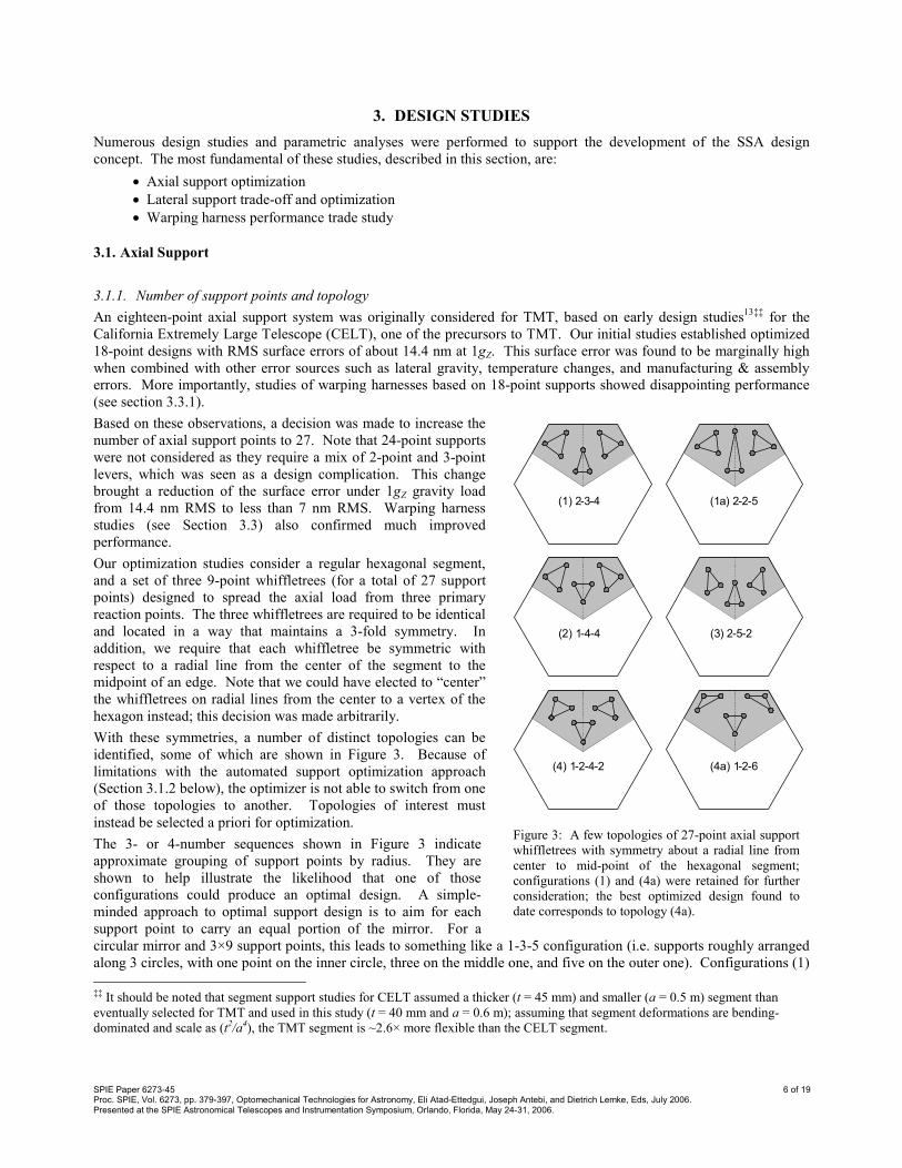
Our optimization studies consider a regular hexagonal segment,
and a set of three 9-point whiffletrees (for a total of 27 support
points) designed to spread the axial load from three primary
reaction points. The three whiffletrees are required to be identical
and located in a way that maintains a 3-fold symmetry. In
addition, we require that each whiffletree be symmetric with
respect to a radial line from the center of the segment to the
midpoint of an edge. Note that we could have elected to “center”
the whiffletrees on radial lines from the center to a vertex of the
hexagon instead; this decision was made arbitrarily.
With these symmetries, a number of distinct topologies can be
identified, some of which are shown in Figure 3. Because of
limitations with the automated support optimization approach
(Section 3.1.2 below), the optimizer is not able to switch from one
of those topologies to another. Topologies of interest must
instead be selected a priori for optimization.
The 3- or 4-number sequences shown in Figure 3 indicate
approximate grouping of support points by radius. They are
shown to help illustrate the likelihood that one of those
configurations could produce an optimal design. A simple-
minded approach to optimal support design is to aim for each
support point to carry an equal portion of the mirror. For a
circular mirror and 3×9 support points, this leads to something like a 1-3-5 configuration (i.e. supports roughly arranged
along 3 circles, with one point on the inner circle, three on the middle one, and five on the outer one). Configurations (1)
‡‡ It should be noted that segment support studies for CELT assumed a thicker (t = 45 mm) and smaller (a = 0.5 m) segment than
eventually selected for TMT and used in this study (t = 40 mm and a = 0.6 m); assuming that segment deformations are bending-
dominated and scale as (t2/a4), the TMT segment is ~2.6× more flexible than the CELT segment.
(3 ) 2 - 5 - 2
(1 a ) 2 - 2 - 5
( 4a) 1 - 2 - 6
(1) 2 - 3 - 4
( 2) 1 - 4 - 4
( 4) 1 - 2 - 4 - 2
Figure 3: A few topologies of 27-point axial support
whiffletrees with symmetry about a radial line from
center to mid-point of the hexagonal segment;
configurations (1) and (4a) were retained for further
consideration; the best optimized design found to
date corresponds to topology (4a).

SPIE Paper 6273-45 7 of 19 Proc. SPIE, Vol. 6273, pp. 379-397, Optomechanical Technologies for Astronomy, Eli Atad-Ettedgui, Joseph Antebi, and Dietrich Lemke, Eds, July 2006. Presented at the SPIE Astronomical Telescopes and Instrumentation Symposium, Orlando, Florida, May 24-31, 2006.
and (4a) might therefore be expected to perform better than others. Configuration (1) was initially selected for
optimization. We later realized that, for a hexagonal segment, this configuration leads to troublesome sag of the corners
of the segment. This led us to adopt topology (4a), which features support points much closer to the vertices.
3.1.2. Optimization technique
To minimize gravity-induced deformations of the mirror segment, the locations of the axial support points and the
distribution of reaction load among those points must be carefully optimized. For a symmetric 27-point support (Figure
4, left side), this results in 9 independent position variables (αi, i=2,…,5, and ri, i=1,…,5) and 4 independent load
distribution variables (φi, i=1,…,4). Note that the four load distribution variables can also be thought of as defining the
locations of the joints of the whiffletree (keeping symmetry in mind): two coordinates for the joint supporting an outer
triangle (the other outer triangle is a mirror image of the first one), and the radial position of the joints supporting the
inner small plate and the large plate (these two joints are required to lie on the axis of symmetry).
Starting point (initial guess)
Gradient-based Optimizer (Matlab’s NLCON)
Write FE model geometry
Build FE mesh
Calculate segment deformed shape and shape functions
Calculate WT moments that minimize RMS / EE(80) (explicit pseudo-inverse)
Converged?
Support locations & load distribution, RMS or EE(80) error
Support locations
NASTRAN Deck
1g shape + 4 shape functions
Femap script
Optimal support locations & load distribution
Outer Problem (support positions)
Inner Problem (load distribution)
*
†
‡
*
*
r1 r2
x
y
φ1
r3 r4
φ2
φ4
α5
α4 φ3
α3
α2
r5
*MATLAB †Femap ‡NASTRAN
Performed within:
Figure 4: Axial support optimization; left: design variables for a 27-point support; right: algorithmic implementation of
the optimization problem.
For a given set of position variables, adjusting the load distribution variables is a linear superposition problem that can
be solved explicitly. Starting from a nominal load distribution (nominal values of the load distribution variables φi, for
example a uniform distribution), five distinct finite element solutions are calculated: the deformation of the segment
under a 1gZ (axial) load, and the responses of the segment to moments applied at the whiffletree joints, simulating
perturbations of the locations of those joints (i.e. the balance of the whiffletree, or the load distribution between the nine
support points) while maintaining symmetry. The problem of defining an optimal whiffletree balance is one of
minimizing the surface error (e.g. its RMS value) of a linear combination of these five load cases (after removing the
piston component of surface deflection).
This whiffletree balancing technique can be taken advantage of in separating the optimization problem between two
levels: the support point position optimization is performed as a non-linear, bounded, gradient–based search (outer
problem, 9 design variables), while for any given set of these position variables, the load distribution (whiffletree
balance) is optimized as a least square superposition of shape functions (inner problem, 4 design variables). This

SPIE Paper 6273-45 8 of 19 Proc. SPIE, Vol. 6273, pp. 379-397, Optomechanical Technologies for Astronomy, Eli Atad-Ettedgui, Joseph Antebi, and Dietrich Lemke, Eds, July 2006. Presented at the SPIE Astronomical Telescopes and Instrumentation Symposium, Orlando, Florida, May 24-31, 2006.
process was programmed using a combination of the Finite Element (FE) pre-processor FEMAP14, the FE solver
MSC/NASTRAN15, and MATLAB
16, as illustrated in Figure 4. The two-step approach optimization was found to
accelerate convergence of the solution.
3.1.3. Optimization results
As shown in Table 3, the axial support optimization results clearly indicate that 27-point topology (4a) of Figure 3 gives
the best performance compared to the other topologies investigated.
Topology RMS, nm P-V, nm Max surface slope, nm/m
18-pt 14.4 92.5 -
27-pt (1) 10.69 71.2 516
27-pt (4a) 6.33 37.0 431
Table 3: Axial support optimization results for several topologies investigated (refer to Figure 3 for descriptions of the
27-point topologies).
Optimization results, taken directly from the simplified optimization model, are shown in Figure 5 (left side) for the 27-
point topology (4a). A more detailed assessment of the same design was later performed, leading to the axial
displacement and slope contour plots also shown in Figure 5 (center and right).
-10
-10
-10
-10
0 0
0
0
0
0
0
0
0
1010
10
10
10
10
10
10
20 20
RMS = 6.33 nm P-V = 37.0 nm Max Slope = 431 nm/m
Figure 5: Optimized axial support using topology (4a) of Figure 3. Left: the three sectors show, clockwise from top: a)
1gZ surface deformation (nm), b) whiffletree configuration, c) locations of the optimized support points (blue
circles) within the design variable bounds (green boxes); Red stars show the locations of the whiffletree
joints. Middle and right: surface error and slope maps from a more detailed analysis of the same design.
3.2. Lateral Support
Separate and largely independent from the axial support, the lateral support system transmits in-plane gravity loads (FX,
FY, MZ) to the moving frame. Traditionally, in large segmented telescopes, this has been achieved with a thin diaphragm
flexure located near the center of mass of the mirror segment, inside a relatively large circular pocket machined into the
back side of the segment. Keck, SALT, GTC, HET, and LAMOST all use some variation of central diaphragm support.
Several support concepts were investigated for TMT; they are described in the next two sections.
3.2.1. Lateral support development
Guided by an initial desire not to machine holes or pockets into the mirror segment, we explored designs that mounted
directly to the back surface of the mirror. This somewhat unique no-drilling requirement was motivated by the cost and
perceived risk associated with drilling large recesses into LE glass blanks. It led to the development of a triple-bipod
support (Figure 6), which is comprised of three sets of bipod flexures mounted 120 degrees apart on a circle of given
radius. This mechanism effectively supports the segment at three virtual points inside the glass, but without the need to
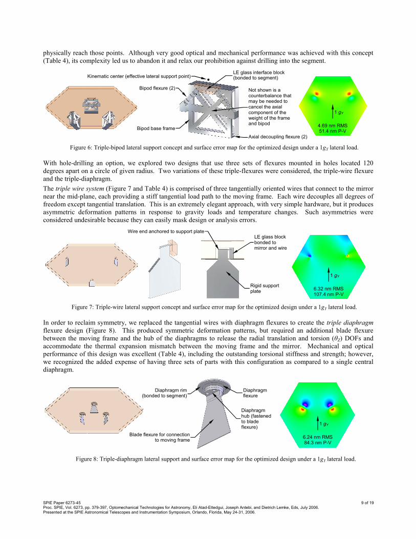
SPIE Paper 6273-45 9 of 19 Proc. SPIE, Vol. 6273, pp. 379-397, Optomechanical Technologies for Astronomy, Eli Atad-Ettedgui, Joseph Antebi, and Dietrich Lemke, Eds, July 2006. Presented at the SPIE Astronomical Telescopes and Instrumentation Symposium, Orlando, Florida, May 24-31, 2006.
physically reach those points. Although very good optical and mechanical performance was achieved with this concept
(Table 4), its complexity led us to abandon it and relax our prohibition against drilling into the segment.
LE glass interface block (bonded to segment)
Bipod flexure (2)
Bipod base frame
Axial decoupling flexure (2)
Kinematic center (effective lateral support point)
Not shown is a counterbalance that may be needed to cancel the axial component of the weight of the frame and bipod 4.69 nm RMS
51.4 nm P-V
1 gY
Figure 6: Triple-bipod lateral support concept and surface error map for the optimized design under a 1gY lateral load.
With hole-drilling an option, we explored two designs that use three sets of flexures mounted in holes located 120
degrees apart on a circle of given radius. Two variations of these triple-flexures were considered, the triple-wire flexure
and the triple-diaphragm.
The triple wire system (Figure 7 and Table 4) is comprised of three tangentially oriented wires that connect to the mirror
near the mid-plane, each providing a stiff tangential load path to the moving frame. Each wire decouples all degrees of
freedom except tangential translation. This is an extremely elegant approach, with very simple hardware, but it produces
asymmetric deformation patterns in response to gravity loads and temperature changes. Such asymmetries were
considered undesirable because they can easily mask design or analysis errors.
rigid support plate (in Zθ
rigid support plate (in Zθ
LE glass block bonded to mirror and wire
Wire end anchored to support plate
Rigid support plate
6.32 nm RMS 107.4 nm P-V
1 gY
Figure 7: Triple-wire lateral support concept and surface error map for the optimized design under a 1gY lateral load.
In order to reclaim symmetry, we replaced the tangential wires with diaphragm flexures to create the triple diaphragm
flexure design (Figure 8). This produced symmetric deformation patterns, but required an additional blade flexure
between the moving frame and the hub of the diaphragms to release the radial translation and torsion (θZ) DOFs and
accommodate the thermal expansion mismatch between the moving frame and the mirror. Mechanical and optical
performance of this design was excellent (Table 4), including the outstanding torsional stiffness and strength; however,
we recognized the added expense of having three sets of parts with this configuration as compared to a single central
diaphragm.
Diaphragm rim (bonded to segment)
Diaphragm hub (fastened to blade flexure)
Blade flexure for connection to moving frame
Diaphragm flexure
6.24 nm RMS 84.3 nm P-V
1 gY
Figure 8: Triple-diaphragm lateral support and surface error map for the optimized design under a 1gY lateral load.

SPIE Paper 6273-45 10 of 19 Proc. SPIE, Vol. 6273, pp. 379-397, Optomechanical Technologies for Astronomy, Eli Atad-Ettedgui, Joseph Antebi, and Dietrich Lemke, Eds, July 2006. Presented at the SPIE Astronomical Telescopes and Instrumentation Symposium, Orlando, Florida, May 24-31, 2006.
Ultimately, we converged on the traditional central diaphragm concept described in Section 3.2.2. Compared to the
triple diaphragm design, it has 1/3 as many parts, and the radial decoupling flexures are also eliminated. However, the
single diaphragm needs to be larger in diameter to provide the required strength and torsional capacity. This, in-turn,
requires a larger hole in the glass, which causes greater distortion.
It is worth noting that it is the use of the moving frame architecture that permits the consideration of a wider variety of
lateral support architectures since the piston/tip/tilt motions are not imposed on the lateral support flexures. Without the
moving frame, one is forced to employ a central flexure such as a diaphragm. With the moving frame, the triple-flexure
architectures become practical and in some ways, preferable.
Design Comparison Metric Triple-Bipod Triple-Wire Triple-Diaphragm Central Diaphragm
Machining into glass None 3 rectangular pockets
(~ 26L × 20W × 28D mm)
3 circular pockets
(~ Ø70 × 20D mm)
1 circular pocket
(~ Ø120 × 20D mm)
Sensitivity to depth of support point High High High High
Complexity High Medium Medium Low
Part count / cost High Medium Medium Low
Symmetric Yes No Yes Yes
Technical concerns Sensitive to system compliance
Asymmetry,
Bond design (wire to pad and pad to segment)
Fragility of diaphragm Torsional stiffness & strength,
Fragility of diaphragm
Advantages No Machining of glass,
Hardware very accessible
Simplicity High Torsional stiffness Heritage,
Simplicity
1G +Y lateral (nm RMS)*
†
4.7
6.3
6.2
6.4
1G –Z axial (nm RMS)*
†
11.3
11.0
10.7
10.7
1°C ∆T (nm RMS)*
†
1.0
1.1
0.65
0.60
* with design optimized to minimize 1g lateral gravity print-through † with axial support configuration (1) as shown in Figure 3; this is not the final optimized axial support configuration (4a) that was eventually retained as the baseline.
Table 4: Comparison of four lateral support concepts considered for the TMT primary mirror SSA
3.2.2. Central diaphragm support
In an effort to minimize cost and complexity we ultimately adopted the central diaphragm lateral support shown in
Figure 9 as our baseline. The central diaphragm reacts all lateral and torsional mirror loads, transmitting them to the
moving frame via a stiff center-post. It is bonded directly to the bottom of a cylindrical pocket drilled into the segment.
Super Invar is employed for the diaphragm in order to match as closely as possible the thermal expansion of the LE
glass. Since this diaphragm will be subject to extremely small operating deflections, by virtue of the moving frame
concept, it does not require the use of high strength materials. This is important since Super Invar has a rather low yield
strength (276 MPa, or 40 ksi). If the diaphragm required more stroke, then stronger, higher expansion alloys would be
required, and the notion of bonding directly to the glass would not be viable. Other telescopes with larger required
deflection use high strength diaphragms with elaborate decoupling flexures that are costly and difficult to fit into the
40mm thick mirror envelope of TMT.
Diaphragm hub
(fastened to post)
Diaphragm rim (bonded to segment)
Diaphragm flexure
6.39 nm RMS 113.5 nm P-V
1 gY
Figure 9: Central diaphragm lateral support, and surface error map for the optimized design under a 1gY lateral load
(note that surface deformation plot corresponds to the diaphragm design of Table 4, which is smaller than the
final baseline design used in analyses shown in Figure 15).

SPIE Paper 6273-45 11 of 19 Proc. SPIE, Vol. 6273, pp. 379-397, Optomechanical Technologies for Astronomy, Eli Atad-Ettedgui, Joseph Antebi, and Dietrich Lemke, Eds, July 2006. Presented at the SPIE Astronomical Telescopes and Instrumentation Symposium, Orlando, Florida, May 24-31, 2006.
Of concern with the direct-bond diaphragm concept is the reliance on attaining predictable, stable, low expansion
characteristics with Super-Invar. We initiated a detailed study to assess the viability of including strain relieving
features into the diaphragm geometry. In brief, it was found that a substantial reduction in thermal distortion loads may
be attained by adding a circumferential convolution to the diaphragm OD in addition to radial slots in the outer rim.
This concept may be further developed in later phases of the project.
3.3. Warping harness
Although every effort will be made to ensure that the primary mirror segments are carefully cast, machined, polished,
and final-figured, and supported on well designed and assembled optimized support systems, experience with other
telescope mirrors has shown that factors beyond our control may result in unacceptable distortions of the optical surface
when installed on the telescope. Additionally, simulations show that thermal distortion of the segments may be one of
the largest contributions to figure error. Since temperature changes are generally slow, their effect can be partially
corrected by periodically readjusting warping harnesses throughout the night. This, together with the large number of
warping harness degrees of freedom in the PM (over 13,000), is the key motivation for pursuing an automated warping
harness system for TMT.
The requirements presented in Section 2.3.2 define a system capable of correcting more than 93% of focus and
astigmatism errors, and 80% of coma & trefoil errors. It was decided that higher order Zernike correction capability was
not desirable since small errors in the large force magnitudes required to make higher order corrections are likely to
induce significant low frequency errors, possibly doing more harm than good.
The whiffletree axial support mechanism lends itself to a straight-forward implementation of a warping harness. By
imposing discrete moments at whiffletree joints, it is possible to alter the load distribution in the rod flexures supporting
the mirror and cause a change in surface figure. This approach has been successfully implemented on Keck and other
telescopes. At Keck, the warping harness is manually adjusted, but for TMT the sheer number of segments requires
automation.
Warping harness performance has been one of the driving factors in establishing the order and topology of the axial
support system. Preliminary studies identified that a warping harness based on an 18-point whiffletree could not
command the required level of correction. Based on these results, the design focused on a higher order topology, the 27-
point whiffletree.
Given the large number of mirror segments required for TMT, minimizing the number of warping harness actuators on
each SSA is essential to control costs. Our studies systematically determine the minimum set of actuators required. For
the 27 point whiffletree topologies we studied (cases 1 and 4a in Figure 3) we found that it was possible to reduce the
required number of actuators on each SSA from the full complement of 24 to 18, resulting in a cost reduction of
approximately 25%.
3.3.1. Performance predictions
For any axially kinematic whiffletree of order N, there are N-3 independent degrees of freedom which can be acted upon
by a warping harness. For the case of the 18- and 27-point whiffletrees, each whiffletree joint has two independent
degrees of freedom. These degrees of freedom can be acted upon by placing a pair of moment actuators (orthogonal to
one-another) across each joint. Each actuator applies equal and opposite moments to the members on each side of the
joint. For the 18-point whiffletree, the maximum number of independent moment actuators is 15, and for the 27-point
system the maximum number is 24.
Analytical simulations were performed to predict the performance of these whiffletree-based warping harness
configurations. The calculations were performed in the following steps to determine the optimum arrangement of
actuators that satisfy the requirements:
1. FEA calculations are performed to determine the influence functions (in terms of optical surface distortion) for each actuator input.
2. For each prescribed aberration (Zernike term), a least squares fit is performed (using SigFit14) to minimize the residual RMS surface distortion using a linear combination of the actuator influence functions. The result is a
prediction of the corrected surface distortion along with the amplitudes of the required actuator inputs.
3. The calculations of step 2 are repeated systematically with various selections of active actuators until a minimum set of actuators can be chosen that achieves the required performance.

SPIE Paper 6273-45 12 of 19 Proc. SPIE, Vol. 6273, pp. 379-397, Optomechanical Technologies for Astronomy, Eli Atad-Ettedgui, Joseph Antebi, and Dietrich Lemke, Eds, July 2006. Presented at the SPIE Astronomical Telescopes and Instrumentation Symposium, Orlando, Florida, May 24-31, 2006.
The calculations described above were performed for three candidate whiffletree designs: the 18-point, and the two 27-
point topologies previously mentioned, using the Zernike term amplitudes specified in Table 2. Comparing results for
these three topologies (Table 5), using the full complement of actuators for each topology, we see that the 18-point
whiffletree results do not meet requirements, and that both 27-point topologies provide the required performance with
some margin. The maximum actuator moments, also shown in the table, are similar for all three topologies.
18-point Whiffletree 27-Point, Topology (1) 27-Point, Topology (4a)
15 Actuators 24 Actuators 24 Actuators
Initial Corrected Percent Reduction Corrected Percent Reduction Corrected Percent Reduction
Aberration RMS, nm RMS,nm Removed Factor RMS,nm Removed Factor RMS,nm Removed Factor
Focus (Z20) 258.2 30.6 88.2 8.4 11.6 95.5 22.3 14.0 94.6 18.5
Astigmatism (Z22) 341.6 10.1 97.1 33.9 5.9 98.3 57.7 6.3 98.2 54.1
Astigmatism (Z2-2) 341.6 10.1 97.1 33.9 5.9 98.3 57.7 6.3 98.2 54.1
Coma (Z31) 31.7 9.7 69.5 3.3 4.9 84.6 6.5 5.3 83.3 6.0
Coma (Z3-1) 31.7 9.7 69.5 3.3 4.9 84.6 6.5 5.3 83.3 6.0
Trefoil (Z33) 60.7 5.6 90.8 10.9 3.9 93.6 15.5 2.0 96.8 31.0
Trefoil (Z3-3) 47.5 4.9 89.6 9.6 2.5 94.7 18.7 5.9 87.5 8.0
Max Actuator Moment, N-m 2.97 3.38 3.11
Table 5: Comparison of warping harness performance for three axial support topologies, using the maximum
compliment of actuators. 27-point topologies (1) and (4a) are described in Figure 3. RMS reduction factors
that do not meet requirements are underlined. Also shown is the maximum actuator moment required for
each topology.
Xssa
Yssa
M_outer (r, θ), 6ea.
M_inner(r, θ), 3ea.
M_act(r, θ), 3ea.
Figure 10: Schematic of 27-point whiffletree topology (4a) including warping harness moment locations. Each moment
vector represents an equal and opposite moment set acting across one pivot.
The axial support optimization (Section 3.1.3) identified 27-point topology (4a) as having the best performance and it
was chosen as the baseline design. The corresponding warping harness design was further analyzed to determine a
minimum set of actuators for this topology. Figure 10 shows the arrangement of applied moments used to represent the
actuators. The results from the study, shown in Table 6, clearly identify actuator arrangement Case-10 as providing the
required performance with the minimum number of actuators. It is worth noting that the selected arrangement (Case-10)
also has one of the lowest required actuator inputs, further emphasizing the efficiency of the configuration.
SPIE Paper 6273-45 13 of 19 Proc. SPIE, Vol. 6273, pp. 379-397, Optomechanical Technologies for Astronomy, Eli Atad-Ettedgui, Joseph Antebi, and Dietrich Lemke, Eds, July 2006. Presented at the SPIE Astronomical Telescopes and Instrumentation Symposium, Orlando, Florida, May 24-31, 2006.
Case: 1 (All) 2 3 4 5 6 7 8 9 10 (3+7) 11 (3+9)
# Actuators Eliminated: 0 6 3 3 6 6 3 3 6 6 9
# Actuators Active: 24 18 21 21 18 18 21 21 18 18 15
Eliminated Actuator
Locations: -
Mact_r
Mact_θ Mact_r Mact_θ Mouter_r Mouter_θ Minner_r Minner_θ
Minner_r
Minner_θ
Minner_r,
Mact_r
Minner_r&θ
Mact_r Rqmt
Focus (Z20) 18.5 4.7 18.5 4.7 18.4 16.2 18.5 12.4 12.4 18.5 12.4 15.0
Astigmatism (Z22) 54.1 36.2 49.9 43.3 31.5 40.4 43.1 53.9 53.9 42.5 42.4 15.0
Astigmatism (Z2-2) 54.1 36.2 49.9 43.3 31.5 40.4 43.1 53.9 53.9 42.5 42.4 15.0
Coma (Z31) 6.0 5.8 5.8 6.0 5.3 4.8 5.5 5.1 5.1 5.4 4.6 5.0
Coma (Z3-1) 6.0 5.8 5.8 6.0 5.3 4.8 5.5 5.1 5.1 5.4 4.6 5.0
Trefoil (Z33) 31.0 29.4 29.4 31.0 31.0 15.4 28.9 31.0 31.0 28.4 28.4 5.0
Trefoil (Z3-3) 8.0 3.1 8.0 3.1 1.0 8.0 8.0 8.0 8.0 8.0 8.0 5.0
Max Actuator Moment, N-m 3.1 7.6 3.9 7.6 4.3 3.1 2.9 3.6 3.6 2.9 3.6
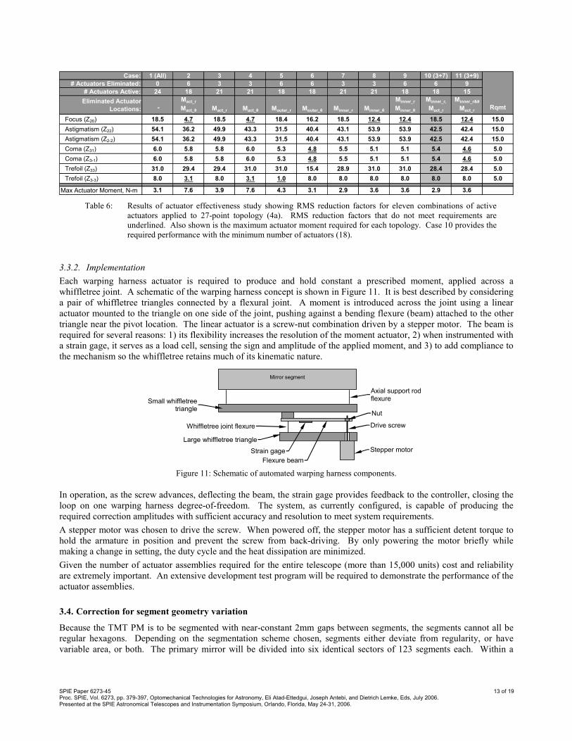
Table 6: Results of actuator effectiveness study showing RMS reduction factors for eleven combinations of active
actuators applied to 27-point topology (4a). RMS reduction factors that do not meet requirements are
underlined. Also shown is the maximum actuator moment required for each topology. Case 10 provides the
required performance with the minimum number of actuators (18).
3.3.2. Implementation
Each warping harness actuator is required to produce and hold constant a prescribed moment, applied across a
whiffletree joint. A schematic of the warping harness concept is shown in Figure 11. It is best described by considering
a pair of whiffletree triangles connected by a flexural joint. A moment is introduced across the joint using a linear
actuator mounted to the triangle on one side of the joint, pushing against a bending flexure (beam) attached to the other
triangle near the pivot location. The linear actuator is a screw-nut combination driven by a stepper motor. The beam is
required for several reasons: 1) its flexibility increases the resolution of the moment actuator, 2) when instrumented with
a strain gage, it serves as a load cell, sensing the sign and amplitude of the applied moment, and 3) to add compliance to
the mechanism so the whiffletree retains much of its kinematic nature.
Mirror segment
Small whiffletree triangle
Large whiffletree triangle
Whiffletree joint flexure
Strain gage Stepper motor
Drive screw
Nut
Flexure beam
Axial support rod flexure
Figure 11: Schematic of automated warping harness components.
In operation, as the screw advances, deflecting the beam, the strain gage provides feedback to the controller, closing the
loop on one warping harness degree-of-freedom. The system, as currently configured, is capable of producing the
required correction amplitudes with sufficient accuracy and resolution to meet system requirements.
A stepper motor was chosen to drive the screw. When powered off, the stepper motor has a sufficient detent torque to
hold the armature in position and prevent the screw from back-driving. By only powering the motor briefly while
making a change in setting, the duty cycle and the heat dissipation are minimized.
Given the number of actuator assemblies required for the entire telescope (more than 15,000 units) cost and reliability
are extremely important. An extensive development test program will be required to demonstrate the performance of the
actuator assemblies.
3.4. Correction for segment geometry variation
Because the TMT PM is to be segmented with near-constant 2mm gaps between segments, the segments cannot all be
regular hexagons. Depending on the segmentation scheme chosen, segments either deviate from regularity, or have
variable area, or both. The primary mirror will be divided into six identical sectors of 123 segments each. Within a
SPIE Paper 6273-45 14 of 19 Proc. SPIE, Vol. 6273, pp. 379-397, Optomechanical Technologies for Astronomy, Eli Atad-Ettedgui, Joseph Antebi, and Dietrich Lemke, Eds, July 2006. Presented at the SPIE Astronomical Telescopes and Instrumentation Symposium, Orlando, Florida, May 24-31, 2006.
sector, each of the 123 segment types has a unique geometry. Differences between segments range from sub-millimeter
magnitude, up to 9 mm or so, again depending on the segmentation scheme employed.
Cost considerations clearly do not permit designing a different support system for each of the 123 segment types.
Instead, the support system is designed for a nominal segment, and then re-tuned for each segment type with a minimum
impact on the design. At Keck, this was achieved through the use of “SuperHex” weights, attached near the edge of the
segment to re-balance the segment and make it behave like the nominal geometry (designated as “SuperHex” because, at
Keck, it envelopes the outlines of all segment types). Three options were considered for TMT: balance weights on the
segment, balance weights on the whiffletrees, and customized locations of WT pivot-points for each segment type.
Since part count and excess mass are both cost drivers, it was decided to avoid the hex-weighting approach in favor of
customizing the whiffletree pivot-points for each segment type. With this approach, the whiffletree components are
manufactured identically, but the holes used to locate the pivot flexures are drilled in specific, unique locations for each
segment type. Detailed calculations are still pending to fully verify this approach, including the determination of the
magnitudes of geometric correction required and the resulting optical performance. The final selection of the
segmentation scheme will be made when the results of this study are available.
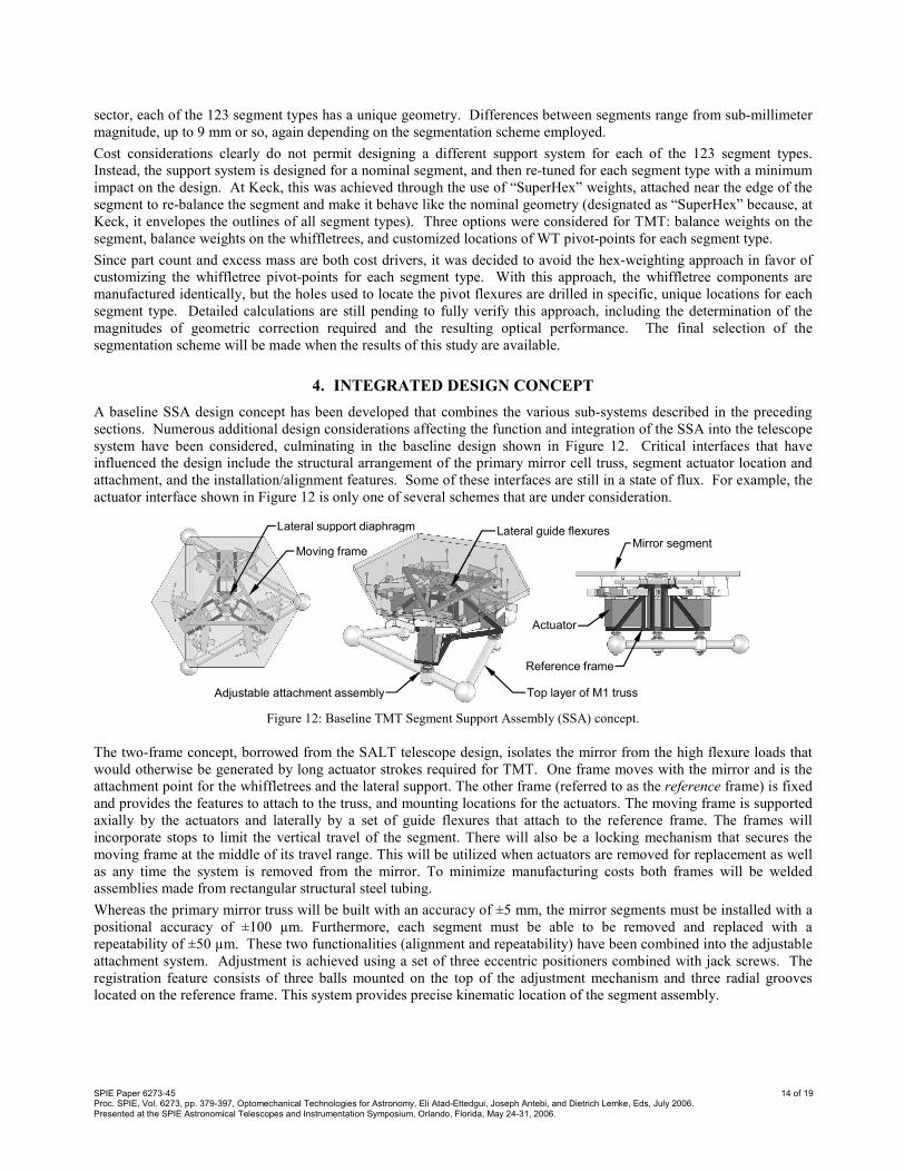
4. INTEGRATED DESIGN CONCEPT
A baseline SSA design concept has been developed that combines the various sub-systems described in the preceding
sections. Numerous additional design considerations affecting the function and integration of the SSA into the telescope
system have been considered, culminating in the baseline design shown in Figure 12. Critical interfaces that have
influenced the design include the structural arrangement of the primary mirror cell truss, segment actuator location and
attachment, and the installation/alignment features. Some of these interfaces are still in a state of flux. For example, the
actuator interface shown in Figure 12 is only one of several schemes that are under consideration.
Lateral support diaphragm
Moving frame
Lateral guide flexures
Adjustable attachment assembly Top layer of M1 truss
Reference frame
Actuator
Mirror segment
Figure 12: Baseline TMT Segment Support Assembly (SSA) concept.
The two-frame concept, borrowed from the SALT telescope design, isolates the mirror from the high flexure loads that
would otherwise be generated by long actuator strokes required for TMT. One frame moves with the mirror and is the
attachment point for the whiffletrees and the lateral support. The other frame (referred to as the reference frame) is fixed
and provides the features to attach to the truss, and mounting locations for the actuators. The moving frame is supported
axially by the actuators and laterally by a set of guide flexures that attach to the reference frame. The frames will
incorporate stops to limit the vertical travel of the segment. There will also be a locking mechanism that secures the
moving frame at the middle of its travel range. This will be utilized when actuators are removed for replacement as well
as any time the system is removed from the mirror. To minimize manufacturing costs both frames will be welded
assemblies made from rectangular structural steel tubing.
Whereas the primary mirror truss will be built with an accuracy of ±5 mm, the mirror segments must be installed with a
positional accuracy of ±100 µm. Furthermore, each segment must be able to be removed and replaced with a
repeatability of ±50 µm. These two functionalities (alignment and repeatability) have been combined into the adjustable
attachment system. Adjustment is achieved using a set of three eccentric positioners combined with jack screws. The
registration feature consists of three balls mounted on the top of the adjustment mechanism and three radial grooves
located on the reference frame. This system provides precise kinematic location of the segment assembly.
SPIE Paper 6273-45 15 of 19 Proc. SPIE, Vol. 6273, pp. 379-397, Optomechanical Technologies for Astronomy, Eli Atad-Ettedgui, Joseph Antebi, and Dietrich Lemke, Eds, July 2006. Presented at the SPIE Astronomical Telescopes and Instrumentation Symposium, Orlando, Florida, May 24-31, 2006.
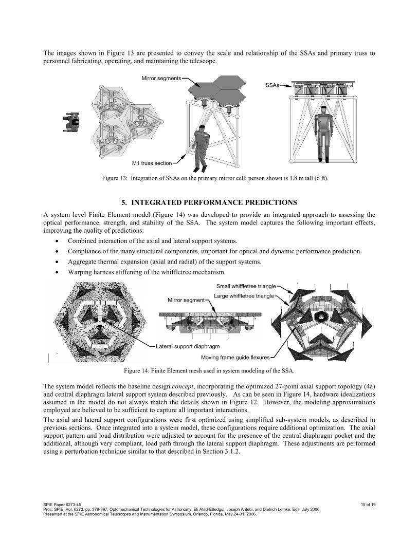
The images shown in Figure 13 are presented to convey the scale and relationship of the SSAs and primary truss to
personnel fabricating, operating, and maintaining the telescope.
M1 truss section
SSAs
Mirror segments
Figure 13: Integration of SSAs on the primary mirror cell; person shown is 1.8 m tall (6 ft).
5. INTEGRATED PERFORMANCE PREDICTIONS
A system level Finite Element model (Figure 14) was developed to provide an integrated approach to assessing the
optical performance, strength, and stability of the SSA. The system model captures the following important effects,
improving the quality of predictions:
• Combined interaction of the axial and lateral support systems.
• Compliance of the many structural components, important for optical and dynamic performance prediction.
• Aggregate thermal expansion (axial and radial) of the support systems.
• Warping harness stiffening of the whiffletree mechanism.
Mirror segmentLarge whiffletree triangle
Small whiffletree triangle
Lateral support diaphragm
Moving frame guide flexures
Figure 14: Finite Element mesh used in system modeling of the SSA.
The system model reflects the baseline design concept, incorporating the optimized 27-point axial support topology (4a)
and central diaphragm lateral support system described previously. As can be seen in Figure 14, hardware idealizations
assumed in the model do not always match the details shown in Figure 12. However, the modeling approximations
employed are believed to be sufficient to capture all important interactions.
The axial and lateral support configurations were first optimized using simplified sub-system models, as described in
previous sections. Once integrated into a system model, these configurations require additional optimization. The axial
support pattern and load distribution were adjusted to account for the presence of the central diaphragm pocket and the
additional, although very compliant, load path through the lateral support diaphragm. These adjustments are performed
using a perturbation technique similar to that described in Section 3.1.2.
SPIE Paper 6273-45 16 of 19 Proc. SPIE, Vol. 6273, pp. 379-397, Optomechanical Technologies for Astronomy, Eli Atad-Ettedgui, Joseph Antebi, and Dietrich Lemke, Eds, July 2006. Presented at the SPIE Astronomical Telescopes and Instrumentation Symposium, Orlando, Florida, May 24-31, 2006.
The axial (Z) position of the lateral support diaphragm is a very sensitive design parameter. It must be carefully adjusted
using a detailed model that accounts for the complex interactions between sub-systems. This adjustment is also
performed using perturbation techniques.
5.1. Figure Errors
Gravity induced errors for 1g unit-loads (X, Y, Z), in addition to a unit 1°C temperature change are the simplest metrics
for evaluating system level optical performance. A more detailed approach is to use these results to develop elevation
dependent RMS performance curves for comparison to the requirements described in Section 2.3.1.
Sensitivity to manufacturing and assembly errors is another important consideration. These effects have not yet been
evaluated systematically. They will be assessed and managed appropriately in future design phases.
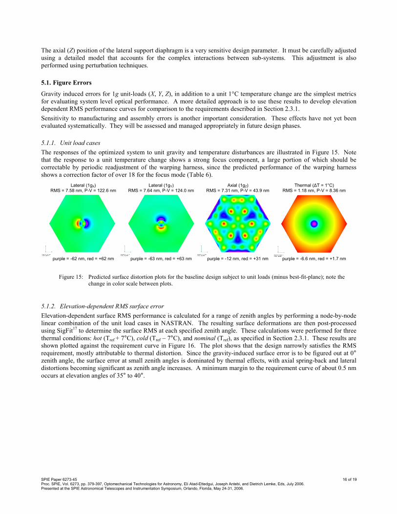
5.1.1. Unit load cases
The responses of the optimized system to unit gravity and temperature disturbances are illustrated in Figure 15. Note
that the response to a unit temperature change shows a strong focus component, a large portion of which should be
correctable by periodic readjustment of the warping harness, since the predicted performance of the warping harness
shows a correction factor of over 18 for the focus mode (Table 6).
Lateral (1gX) RMS = 7.58 nm, P-V = 122.6 nm
Lateral (1gY) RMS = 7.64 nm, P-V = 124.0 nm
Axial (1gZ) RMS = 7.31 nm, P-V = 43.9 nm
Thermal (∆T = 1°C) RMS = 1.18 nm, P-V = 8.36 nm
purple = -62 nm, red = +62 nm purple = -63 nm, red = +63 nm purple = -12 nm, red = +31 nm purple = -6.6 nm, red = +1.7 nm
Figure 15: Predicted surface distortion plots for the baseline design subject to unit loads (minus best-fit-plane); note the
change in color scale between plots.
5.1.2. Elevation-dependent RMS surface error
Elevation-dependent surface RMS performance is calculated for a range of zenith angles by performing a node-by-node
linear combination of the unit load cases in NASTRAN. The resulting surface deformations are then post-processed
using SigFit17 to determine the surface RMS at each specified zenith angle. These calculations were performed for three
thermal conditions: hot (Tref + 7°C), cold (Tref – 7°C), and nominal (Tref), as specified in Section 2.3.1. These results are shown plotted against the requirement curve in Figure 16. The plot shows that the design narrowly satisfies the RMS
requirement, mostly attributable to thermal distortion. Since the gravity-induced surface error is to be figured out at 0° zenith angle, the surface error at small zenith angles is dominated by thermal effects, with axial spring-back and lateral
distortions becoming significant as zenith angle increases. A minimum margin to the requirement curve of about 0.5 nm
occurs at elevation angles of 35° to 40°.

SPIE Paper 6273-45 17 of 19 Proc. SPIE, Vol. 6273, pp. 379-397, Optomechanical Technologies for Astronomy, Eli Atad-Ettedgui, Joseph Antebi, and Dietrich Lemke, Eds, July 2006. Presented at the SPIE Astronomical Telescopes and Instrumentation Symposium, Orlando, Florida, May 24-31, 2006.
0
5
10
15
20
25
0 10 20 30 40 50 60 70 80
Segment zenith angle , degrees.
Surface RMS, nm
Requirement
1g + Hot
1g + Cold
1g
Figure 16: RMS Surface error vs. zenith angle (minus best fit plane); plotted are the requirement curve, gravity effects
only, and gravity effects combined with hot and cold temperature extremes.
5.2. Stiffness
Two measures of system stiffness are relevant: vibration mode frequencies and static stiffness. The former is important
in relation to transmission of vibration and in terms of control system response, whereas the latter is relevant to the
positional stability of the mirror and its ability to resist wind loading.
5.2.1. Vibration frequencies
Frequencies and mode shapes for a few important vibration modes are shown in Figure 17. All modes meet the 35 Hz
requirement, with the exception of the torsional (clocking) mode (~20 Hz). This is considered acceptable since it is
difficult to excite this mode on the telescope. It should be noted that the current model does not include compliance
from the reference frame or the PM cell; the design may require adjustments once those compliances are taken into
account.
Z
Y
Z
X
Mode 1: 20.3 Hz (torsion) Mode 2: 36.9 Hz (RY rocking) Mode 4: 54.1 Hz (piston)
Figure 17: Predicted vibration mode shapes.
5.2.2. Static Stiffness
When subjected to a uniform pressure applied to the optical surface in the Z direction, the mirror pistons uniformly,
corresponding to a 12.2 N/µm stiffness. This calculation includes the compliance of the actuators (assumed 11 N/µm),
actuator flexures, but not the reference frame or SSA cell truss. If the actuator is assumed to act rigidly for low
frequency excitation, the piston stiffness of the SSA increases to 19.4 N/µm.
SPIE Paper 6273-45 18 of 19 Proc. SPIE, Vol. 6273, pp. 379-397, Optomechanical Technologies for Astronomy, Eli Atad-Ettedgui, Joseph Antebi, and Dietrich Lemke, Eds, July 2006. Presented at the SPIE Astronomical Telescopes and Instrumentation Symposium, Orlando, Florida, May 24-31, 2006.
6. CONCLUSIONS
Detailed conceptual design studies for the TMT segment support assemblies have been presented. Baseline concepts
have been selected for the three most important sub-systems, namely the axial support, lateral support, and warping
harness.
An innovative, two-level axial support optimization technique was described. It enabled us to efficiently and
automatically minimize the print-through of the axial support system under gravity loads and led to the selection of a 27-
point topology that keeps zenith-looking surface figure errors to less than 8 nm.
Several concepts have been studied and presented for lateral support of segmented optics. All of those concepts
achieved remarkable performance (less than 8 nm RMS surface error under 1g lateral load). One of those concepts
avoids the need to drill into the segment, although the relative complexity of its implementation led us to abandon it in
favor of a more classical central diaphragm support.
A warping harness design was presented that is able to reduce second and third order Zernike surface errors by factors of
better than 5, using 18 actuators per segment. This warping harness will be automated to allow periodic re-adjustment of
segment figure while observing.
Key geometric parameters have been carefully optimized using a coupled system model and automated numerical
approaches. The result is a baseline design that meets challenging design requirements for surface figure, stiffness, and
mass.
With the basic design approach now established, future work will include a study of PM segmentation schemes, a
systematic estimation of the effects of manufacturing and assembly tolerances, and a detailed physical optics evaluation
of support-induced slope errors. These studies will be followed by detailed design, leading to component and system
level prototyping and testing.
ACKNOWLEDGEMENTS
The authors gratefully acknowledge the support of the TMT partner institutions. They are the Association of Canadian
Universities for Research in Astronomy (ACURA), the Association of Universities for Research in Astronomy (AURA),
the California Institute of Technology and the University of California. This work was supported, as well, by the Canada
Foundation for Innovation, the Gordon and Betty Moore Foundation, the National Optical Astronomy Observatory,
which is operated by AURA under cooperative agreement with the National Science Foundation, the Ontario Ministry of
Research and Innovation, and the National Research Council of Canada.
REFERENCES
1. Thirty Meter Telescope (TMT), http://www.tmt.org. 2. W. M. Keck Observatory and telescopes, http://www.keckobservatory.org. 3. T. Mast and J. Nelson, “The Status of the W. M. Keck Observatory and Ten Meter Telescope,” in Large Optics
Technology, SPIE Proceedings, Vol. 571, 1985.
4. Southern African Large Telescope (SALT), http://www.salt.ac.za. 5. J. Swiegers and H. Gajjar, “Completion of the Southern African Large Telescope (SALT) Primary Mirror System,”
in Ground-based Telescopes, J. M. Oschmann, Editor, SPIE Proceedings, Vol. 5489, pp. 881-891, 2004.
6. D. A. H. Buckley, J. G. Meiring, J. Swiegers, and G. Swart, “Many segments and a few dollars: SALT solutions for ELTs,” in Second Bäckaskog Workshop on Extremely Large Telescopes, A. L. Ardeberg & T. Andersen, Editors,
SPIE Proceedings, Vol. 5382, pp. 245-256, 2004.
7. D. Blanco et al., “The SALT Mirror Mount: a high performance, low cost mount for segmented mirrors,” in Future Giant Telescopes, J. R. Angel & R. Gilmozzi, Editors, SPIE Proceedings, Vol. 4840, pp. 527-532, 2003.
8. Hobby-Eberly Telescope (HET), http://www.as.utexas.edu/mcdonald/het/het.html. 9. Gran Telescopio Canarias (GTC), http://www.gtc.iac.es. 10. Large Sky Area Multi-Object Fiber Spectroscopic Telescope (LAMOST), http://www.lamost.org/en. 11. X. Gong, X. Cui, and X. Ye, “Current Progress in the Research of LAMOST Primary Mirror Support,” in
Astronomical Structures and Mechanisms Technology, J. Antebi & D. Lemke, Editors, SPIE Proceedings, Vol.
5495, pp. 499-505, 2004.
12. Born, M. & Wolf, E., Principles of Optics, Pergamon Press, New York, 1964.

SPIE Paper 6273-45 19 of 19 Proc. SPIE, Vol. 6273, pp. 379-397, Optomechanical Technologies for Astronomy, Eli Atad-Ettedgui, Joseph Antebi, and Dietrich Lemke, Eds, July 2006. Presented at the SPIE Astronomical Telescopes and Instrumentation Symposium, Orlando, Florida, May 24-31, 2006.
13. S. Gunnels, “Concept Design Report – Mirror Segment Support System – California Extremely Large Telescope,” Paragon Engineering, CA, March 2001, available at http://celt.ucolick.org/reports_notes.html.
14. FEMAPTM Users Manual, Version 8.3.0.1, UGS Corporation, www.ugs.com. 15. MSC/NASTRAN Users Manual, Version 70.5, 1998, http://www.mscsoftware.com/products/nastran.cfm. 16. MATLAB Users Manual, Release 14, 2005, www.mathworks.com. 17. SigFit Reference Manual, Version 2004-R1. Sigmadyne Inc, http://www.sigmadyne.com/sigweb/sigfit.htm.