Development of rock bolt grout and shotcrete for rock ... · PDF fileTänd ett lager: P, R...
36
Svensk Kärnbränslehantering AB Swedish Nuclear Fuel and Waste Management Co Box 250, SE-101 24 Stockholm Phone +46 8 459 84 00 R-11-08 Development of rock bolt grout and shotcrete for rock support and corrosion of steel in low-pH cementitious materials Anders Bodén, Vattenfall Power Consultant AB Stig Pettersson, Svensk Kärnbränslehantering AB April 2011
Transcript of Development of rock bolt grout and shotcrete for rock ... · PDF fileTänd ett lager: P, R...

Svensk Kärnbränslehantering ABSwedish Nuclear Fueland Waste Management Co
Box 250, SE-101 24 Stockholm Phone +46 8 459 84 00
R-11-08
CM
Gru
ppen
AB
, Bro
mm
a, 2
011
Development of rock bolt grout and shotcrete for rock support and corrosion of steel in low-pH cementitious materials
Anders Bodén, Vattenfall Power Consultant AB
Stig Pettersson, Svensk Kärnbränslehantering AB
April 2011

Tänd ett lager: P, R eller TR.
Development of rock bolt grout and shotcrete for rock support and corrosion of steel in low-pH cementitious materials
Anders Bodén, Vattenfall Power Consultant AB
Stig Pettersson, Svensk Kärnbränslehantering AB
April 2011
ISSN 1402-3091
SKB R-11-08
Keywords: Low-pH concrete, Grout, Repository, Shotcrete, Corrosion.
This report concerns a study which was conducted for SKB. The conclusions and viewpoints presented in the report are those of the authors. SKB may draw modified conclusions, based on additional literature sources and/or expert opinions.
A pdf version of this document can be downloaded from www.skb.se.

R-11-08 3
Preface
This report summarizes results achieved during 2008 and 2009 in SKB’s development of low-pH rock bolt grout and shotcrete for rock support as well as corrosion of steel in low-pH cementitious materials.
The theoretical work and initial mix design was carried out at the Swedish Cement and Concrete Research Institute (CBI), Stockholm and Borås. Laboratory testing of mixes was done at Vattenfall Research and Development AB, Älvkarleby, while field tests were carried out at Äspö Hard Rock Laboratory. Swerea KIMAB AB, Stockholm, has been responsible for the corrosion studies on field exposed specimens.
Stockholm April 2011
Stig Pettersson

R-11-08 5
Summary
It is foreseen that cementitious products will be utilized in the construction of the final repository. The use of conventional cementitious material creates pulses in the magnitude of pH 12–13 in the leachates and release alkalis. Such a high pH is detrimental mainly to impairment of bentonite functioning, but also to possibly enhanced dissolution of spent fuel and alteration of fracture filling materials. It also complicates the safety analysis of the repository, as the effect of a high pH-plume should be considered in the evaluation. As no reliable pH-plume models exist, the use of products giving a pH below 11 in the leachates facilitates the safety analysis, although limiting the amount of low-pH cement is recommended.
In earlier studies it was found that shotcreting, standard casting and rock bolting with low-pH cement (pH ≤ 11 in the leachate) should be possible without any major development work. This report summarizes the results of development work done during 2008 and 2009 in the fields of low-pH rock bolt grout, low-pH shotcrete and steel corrosion in low-pH concrete.
Development of low-pH rock bolt grout mixes and laboratory testing of the selected grout was followed by installation of twenty rock bolts for rock support at Äspö HRL using the chosen low-pH grout. The operation was successful and the bolts and grout are subject to follow up the next ten years.
Low-pH shotcrete for rock support was initially developed within the ESDRED project, which was an Integrated Project within the European Commission sixth framework for research and technologi-cal development. ESDRED is an abbreviation for Engineering Studies and Demonstrations of Repository Designs. ESDRED was executed from 1st February 2004 to 31st January 2009.
The development of the mix design described in this report was based on the results from ESDRED. After laboratory testing of the chosen mix, it was field tested in niche NASA 0408A at Äspö HRL. Further, some areas in the TASS-tunnel were shotcreted as part of the actual rock support. The field tests at Äspö HRL were successful and the fibre rebound was in the same range as for ordinary shotcrete.
An expected increased risk for steel corrosion in low-pH concrete has been investigated via carbonation, electrochemical investigation and field exposure at Äspö HRL. The field exposure will last approximately ten years. So far, the corrosion investigations do not indicate any significantly increased corrosion rate in low-pH concrete.
In summary, from a design point of view, all results so far indicate that low-pH cementitious materials are suitable for use in the final repository.

6 R-11-08
Sammanfattning
I samband med byggandet av slutförvaret kommer cementbaserade produkter att användas. Vid användning av traditionella cementbaserade material frigörs alkali och det uppstår då pH-pulser i storleksordningen 12–13 i lakvattnet. Ett så högt pH är skadlig, huvudsakligen genom påverkan på bentonitens funktion men även till möjlig upplösning av använt bränsle och förändringar av sprick-fyllnadsmaterial. Det försvårar även förvarets säkerhetsanalys, eftersom påverkan av en hög-pH-plym måste tas i beaktande i utvärderingen. Då det inte finns några tillförlitliga beräkningsmodeller för pH-plymer kommer användningen av produkter som ger ett pH under 11 i lakvattnet att förenkla säkerhetsanalysen. Trots det bör mängden låg-pH-cement begränsas.
Tidigare studier av cementbaserade låg-pH-produkter fokuserade på injektering, rapporterat i bland annat Bodén & Sievänen /2005/. I föreliggande rapport sammanfattas det utvecklingsarbete som genomförts inom områdena låg-pH-bultbruk, låg-pH-sprutbetong och stålkorrosion i låg-pH-betong.
Receptutveckling av låg-pH-bultbruk och laboratorieförsök med utvalt bruk följdes av fältförsök i Äspölaboratoriet, där installation av tjugo bergbultar i valt låg-pH-bruk gjorts. Installationen gick problemfritt och bultarna och bultbruket kommer att följas upp under de kommande tio åren.
Sprutbetong av låg-pH-bruk för bergförstärkning utvecklades ursprungligen inom ESDRED-projektet. ESDRED var ett integrerat projekt inom ramen för EU:s sjätte forskningsprogram och genomfördes under perioden 1 februari 2004 till 31 januari 2009. Recepten som beskrivs i denna rapport är baserade på resultaten från ESDRED. Eftersom receptanpassning och kompletterande laboratorietestning av ett utvalt recept har det fälttestats i nisch NASA0408A i Äspölaboratoriet. Som ett led i bergförstärkningen av TASS-tunneln i Äspölaboratoriet har dessutom ett antal bergytor i densamma sprutats med låg-pH-sprutbetong. Sprutningarna i Äspölaboratoriet gick problemfritt och fiberåterstudsen i fältförsöken var av samma storleksordning som i vanlig sprutbetong.
En förväntad ökad risk för stålkorrosion i låg-pH-bruk har studerats genom undersökning av karbonatisering, elektrokemisk undersökning och fältexponering av provkroppar i Äspölaboratoriet. Fältexponeringen är planerad att pågå under tio års tid. Hittills har korrosionsstudierna inte påvisat någon noterbart ökad korrosionsrisk i låg-pH-bruk.
Ur konstruktionsmässig synvinkel pekar sammanfattningsvis alla hittills uppnådda resultat på att cementbaserade låg-pH-material är väl lämpade för användning i slutförvaret.
R-11-08 7
Abbreviations
CBI = Swedish Cement and Concrete Research Institute
ESDRED = Engineering Studies and Demonstrations of Repository Designs
SICADA = SKB’s Site Characterization Database
WCE = Egyptian white cement
Äspö HRL = Äspö Hard Rock Laboratory
R-11-08 9
Contents
1 Introduction 11
2 Objectives 13
3 Low-pH rock bolt grout 153.1 Research programme 153.2 Development of mix design and laboratory testing 153.3 Field testing at Äspö HRL 163.4 Results and conclusions 21
4 Low-pH shotcrete 234.1 Research programme 23
4.1.1 ESDRED 234.1.2 Swedish research 23
4.2 Development of mix design and laboratory testing 234.3 Field testing at Äspö HRL 274.4 Results and conclusions 31
5 Steel corrosion in low-pH concrete 335.1 Carbonation 33
5.1.1 Research programme 335.1.2 Testing 345.1.3 Results and conclusions 34
5.2 Electrochemical investigation 345.2.1 Research programme 345.2.2 Testing 365.2.3 Results and conclusions 37
5.3 Field exposure at Äspö HRL 375.3.1 Research programme 375.3.2 Testing 385.3.3 Results and conclusions 40
6 Results and conclusions 416.1 Rock bolts 416.2 Shotcrete 416.3 Steel corrosion 41
6.3.1 Carbonation and electrochemical investigation 416.3.2 Field exposure at Äspö HRL 42
6.4 Conclusions 42
7 References 43

R-11-08 11
1 Introduction
When constructing the final repository, the use of common construction materials, as steel and con-crete, are foreseen. With respect to the repository long-term safety, a suitable chemical environment is vital. The use of low-pH products is necessary in order to get leachates with a sufficiently low pH (≤ 11).
SKB has been engaged in the development of low-pH cementitious materials since 2001 together with Posiva from Finland. At that time it was concluded that standard casting, rock bolting and shotcreting with low-pH cementitious materials should be possible without any major development work but that low-pH injection grouts would need more development work.
In 2003 the pre-studies on low-pH cementitious materials were followed by a feasibility study. The feasibility study was sponsored by NUMO (Japan), Posiva (Finland) and SKB (Sweden) and involved basic understanding of the structure of low-pH cement paste based on silica fume, fabrica-tion of low-pH cement paste including grinding, rock bolt grout and injection grouting.
In that feasibility study it was found that the development work on injection grouting should be divided into two types, one for larger fractures, i.e. hydraulic aperture ≥ 100 µm, and one for smaller fractures, i.e. hydraulic aperture < 100 µm. This is summarized in Bodén & Sievänen /2005/. SKB continued the development work on low-pH injection grouts and carried out field tests at Äspö HRL, which is partly summarized in Swedish in Funehag /2008/.
Other studies on low-pH cementitious products have been carried out in an integrated project known as ESDRED (Engineering Studies and Demonstrations of Repository Designs). ESDRED was a joint research and development effort by major national radioactive waste management agencies and SKB participated in the project. ESDRED was part of the European Commission’s 6th Euratom Framework Programme for Nuclear Research and Training and was executed from 1st February 2004 to 31st January 2009.
The work on low-pH shotcrete presented in this report is partly based on the results achieved in the ESDRED project for low-pH grout for rock bolts and shotcreting for rock support. The ESDRED co-operation also resulted in a work programme aimed primarily at defining a common protocol for measuring the pH of concretes, as there was no such existing protocol. That project is still ongoing and is scheduled for completing mid 2011.
SKB’s further investigations on self compacting low-pH concrete for tunnel plugs are summarized in Vogt et al. /2009/ and not further described here.
Corrosion of steel in low-pH concretes was also considered to be a potential risk, as the pH is low. A high pH is known to protect the steel from corrosion. The knowledge of corrosion behaviour in low-pH concrete is not known since before. The studies on corrosion of steel in low-pH concretes are summarized in this report.

R-11-08 13
2 Objectives
Cementitious materials are commonly used in conventional tunnelling. The use will create pulses of pH in the magnitude of 12–13 in the leachates and release alkalis. Such a high pH is detrimental and also unnecessarily complicates the safety analysis of the repository, as the effect of a high pH-plume should be considered in the evaluation. No reliable pH-plume models exist to define a safety distance. Risks associated with a high pH-plume are related mainly to impairment of bentonite functioning, but also to possibly enhanced dissolution of spent fuel and alterations of fracture filling materials. The use of products giving a pH below 11 in the leachates facilitates the safety analysis, although limiting the amount of low-pH cement is recommended.
It has been found that, in order to fulfil the requirement to achieve a leachate with a pH of 11 or lower, the binder should contain 40% silica fumeor more. The silica fume used in the investigations summarized here is micro silica from Elkem.
The objective of the work presented in this report is to summarize the development of formulations for rock bolt grout and shotcrete respectively that fulfils the requirement of a leachate with a pH of 11 or lower. Furthermore, the investigations on steel corrosion in low-pH cementitious materials will be summarized.

R-11-08 15
3 Low-pH rock bolt grout
The content of this chapter is mainly based on work carried out at CBI, Swedish Cement and Concrete Research Institute, by Björn Lagerblad and Mikael Westerholm regarding grout development. The field testing at Äspö HRL was coordinated by Magnus Kronberg SKB.
In the following text the term grout will be used both for low-pH rock bolt paste without aggregate and low-pH rock bolt grout with aggregate.
3.1 Research programmeThe development of low-pH cementitious rock bolt grout was done in the following order:
1. Development of mix design.
2. Laboratory testing.
3. Field testing at Äspö HRL.
3.2 Development of mix design and laboratory testingCBI, Swedish Cement and Concrete Research Institute, developed the first formulations for low-pH rock bolt grout in the early 2000’s. The mixes were based on white cement. Since then, research on low-pH cementitious materials has been further developed. Based on the increasing knowledge on how to mix low-pH cementitious materials, new formulations were tested.
Different mixes of low-pH rock bolt pastes without aggregate and low-pH rock bolt grout with aggregate were tested in comparison to a reference rock bolt grout. Different water binder ratios were tested and the yield stress was compared to the reference grout.
The autogenous shrinkage of the grouts recommended for further testing was also measured, Figure 3-1. Autogenous shrinkage can be defined as the unrestrained external bulk deformation taking place under isothermal and sealed conditions with no exchange of water with the surround-ings. It was found that the shrinkage of low-pH paste, without aggregate, is approximately 80% higher than low-pH grout, with aggregate, Figure 3-2.
Figure 3-1. Measuring device for autogenous shrinkage. Courtesy of Björn Lagerblad and Mikael Westerholm, CBI.

16 R-11-08
Table 3-1. Composition of recommended low-pH pastes/grouts for field tests.
Material Low-pH paste w/b 0.40
Low-pH grout w/b 0.475
Ordinary Portland cement CEM I 42.5 N MH/SR/LA 778.9 340Silica Type 920D from ELKEM A/S
519.2 227
Water Local tap water
516.7 266.8
Glenium 51 Solution with 35% active substance
2.9 4.0
Sea sand 0–1 mm – 1,324
3.3 Field testing at Äspö HRLThe niche NASA0408A at Äspö HRL was chosen for testing of rock bolt installations, Figure 3-3. The same niche was later also used for field testing of low-pH shotcrete.
The niche was geologically mapped before the field work started. The mapping was done in accord-ance to an approved specification and the results are documented in SICADA.
A total of 20 bolts were installed, 10 horizontally in the wall and 10 vertically in the crown, Figure 3-4 and 3-5. The bolts will be over cored over a period of time to study the state of the bolts and grout. Four bolts will be over cored at each interval, with two from each grout type. Of these, one of each grout type will be over cored from the vertical installations and one from the horizontal installations.
The first four bolts will be over cored in 2011. Subsequent over coring of bolts will be done at 2, 5 and 10 years from 2011 (2013, 2017 and 2022). The remaining bolts will remain in place for future examination, if required.
Figure 3-2. Autogenous shrinkage of low-pH grouts with and without sea sand as aggregate. Courtesy of Björn Lagerblad and Mikael Westerholm, CBI.

R-11-08 17
Figure 3-3. Niche NASA0408A. This photo was taken by Magnus Kronberg SKB as part of the preparation for the field test.
Figure 3-4. Schematic cross section of niche NASA0408A. Positioning of boreholes viewed from niche towards the tunnel.
The borehole diameter for each bolthole was 46 mm and the depth 4.00-4.05 m. Since the bolts will be over cored later, the importance of straight boreholes was emphasized to the contractor. The direc-tion and straightness of the boreholes was surveyed and the data is stored in SICADA.
18 R-11-08
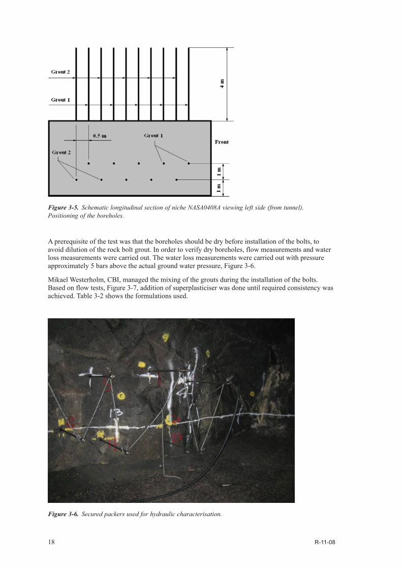
A prerequisite of the test was that the boreholes should be dry before installation of the bolts, to avoid dilution of the rock bolt grout. In order to verify dry boreholes, flow measurements and water loss measurements were carried out. The water loss measurements were carried out with pressure approximately 5 bars above the actual ground water pressure, Figure 3-6.
Mikael Westerholm, CBI, managed the mixing of the grouts during the installation of the bolts. Based on flow tests, Figure 3-7, addition of superplasticiser was done until required consistency was achieved. Table 3-2 shows the formulations used.
Figure 3-5. Schematic longitudinal section of niche NASA0408A viewing left side (from tunnel). Positioning of the boreholes.
Figure 3-6. Secured packers used for hydraulic characterisation.

R-11-08 19
Figure 3-7. Flow test for checking consistency.
Table 3-2. Mixes used in the field tests at Äspö HRL.
Material Low-pH paste w/b 0.40
Low-pH grout w/b 0.475
Ordinary Portland cement CEM I 42.5 N MH/SR/LA
778.8 340.0
Silica Type 920D from ELKEM A/S
519.2 226.7
Water Local tap water
517.3 266.6
Glenium 51 Solution with 35% active substance
2.9 4.0
Sea sand 0–1 mm – 1,324.0
In order to minimize air bubbles, the boreholes were filled with grout from the end of the borehole towards the collar, Figure 3-8. When the boreholes were filled, the bolts were installed. Centring rings were used to centre the bolts in the boreholes. All installed bolts were later tested with a Boltometer. Each bolt was tested six different times. The Boltometer is an electronic instrument for non-destructive examination of grouted rock bolts that operates by transmitting elastic waves into a rock bolt and receiving their echoes by means of a receiver. By interpreting the echograms, the condition of the bolt grout can be evaluated. The only doubtful result, out of totally 120 measure-ments was one with a small end echo exceeding the acceptance curve, see Figure 3-9. The end echo on the 4 m bolt is probably due to an air cushion beyond the bolt. All other rock bolts passed.

20 R-11-08
Figure 3-8. The boreholes were filled from the end of the hole retreating towards the collar in order to minimize the amount of air trapped in the hole.
Figure 3-9. Boltometer diagram for bolt T1. The other five measurements on bolt T1 did not show any echo exceeding the approval curve.
R-11-08 21
3.4 Results and conclusionsAll boreholes were nearly dry. The largest inflow measured was 8 drips/minute and the water loss measurements showed that the surrounding rock was almost free from large water bearing fractures. Hence, no injection grouting to reduce water inflow into the holes was needed.
One hole at a time was filled with grout from the end of the hole towards the collar. The bolt was then pressed into the grout filled hole. There were no problems manually installing the bolts, even if some of the holes were slightly curved.
The Boltometer tests of the installed bolts show good quality grouting of the bolts. Out of 120 Boltometer measurements on the 20 installed bolts, six measurements on each bolt. Only one measurement on one bolt was considered unacceptable while the other five measurements on the same bolt were satisfactory.
So far, installation of rock bolts in low-pH grout does not indicate any particular difficulties.
Over coring of the first bolts is planned to be carried out in 2011.

R-11-08 23
4 Low-pH shotcrete
The content of this chapter is mainly based on work done within the ESDRED project and work carried out by Björn Lagerblad and Mikael Westerholm at CBI, Swedish Cement and Concrete Research Institute, and by Magnus Kronberg, SKB, at Äspö HRL.
4.1 Research programme4.1.1 ESDREDLow-pH shotcrete was initially developed within the ESDRED project (Engineering Studies and Demonstrations of Repository Designs), a joint European Commission research and development programme by major national radioactive waste management agencies and research organisations.
A full-scale demonstration of low-pH shotcrete was carried out within the ESDRED project at Äspö HRL in April 2007. The conclusions from the tests of low-pH shotcrete without fibre reinforcement were that it is possible to make a functional shotcrete with low-pH. It is, however, of vital impor-tance that the concrete is properly mixed. The low-pH concrete requires a powerful mixer, preferably a paddle mixer. Insufficient mixing will give insufficient homogeneity and pumpability, which in turn gives an uneven pressure at the pump. This will result in insufficient mixing of set accelerator and concrete and thus a shotcrete that does not have the necessary stick or set time.
4.1.2 Swedish researchThe further development of low-pH shotcrete formulas for rock support was based on the formula developed in the ESDRED project, with the addition of steel fibres and was done in the following order:
1. Development of mix design and laboratory testing; and
2. Field testing at Äspö HRL.
4.2 Development of mix design and laboratory testingThe development of the mix design was based on the formula for low-pH shotcrete tested within the ESDRED project at Älvkarleby in February 2006, Table 4-1.
The laboratory testing was divided in two parts; Development of mix design at CBI and pilot testing of chosen mix at Vattenfall Research and Development, Älvkarleby.
The aim of the subsequent field testing was to demonstrate the use of low-pH shotcrete with steel fibres in a real situation. No demand was set on flexural strength or toughness index; despite this 50 kg/m3 of 35 mm Dramix steel fibres was used in the tests.
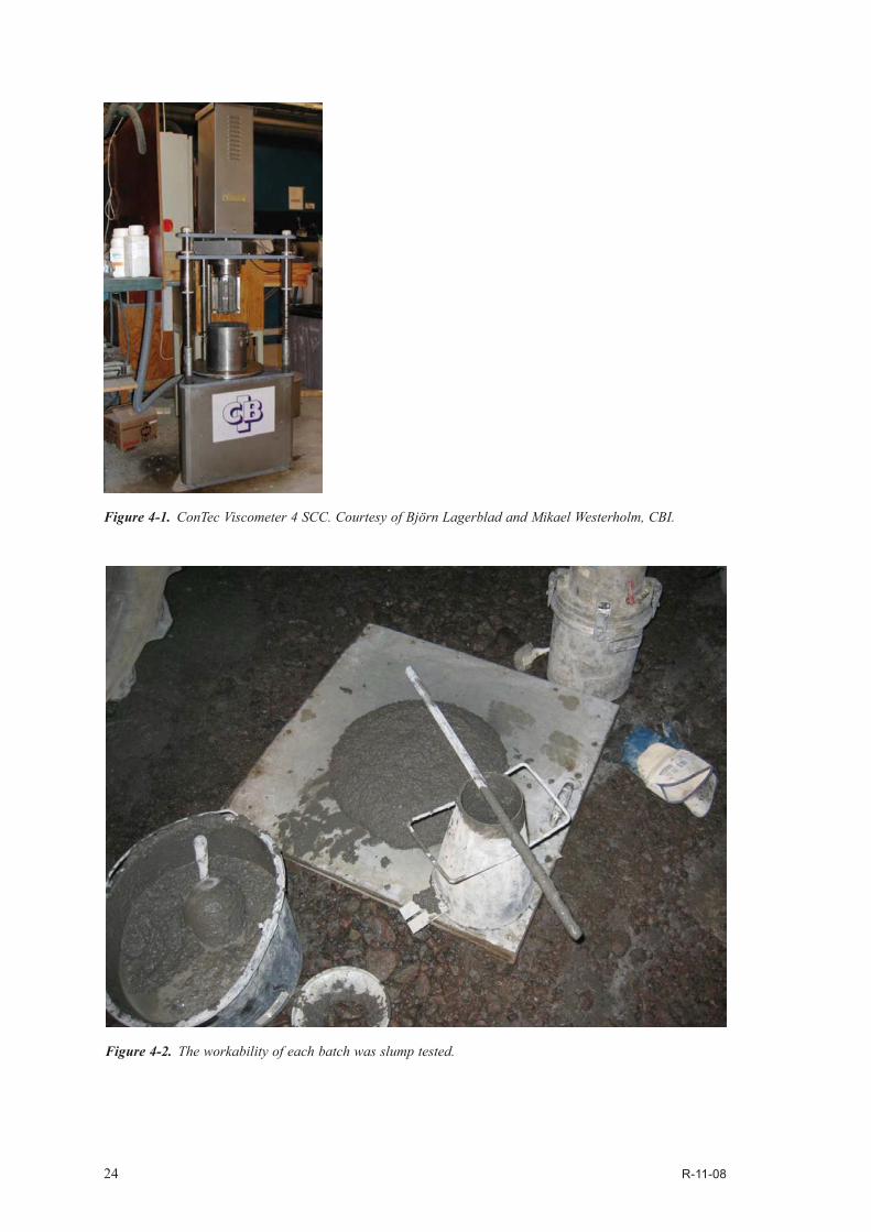
The rheology/workability of different concrete mixes tested at the CBI laboratory was evaluated in order to find a mix design to spray in the pilot test. The rheology of the different concrete mixes was evaluated with a viscometer, ConTec Viscometer 4 SCC, where the measuring system consists of concentric cylinders, Figure 4-1.
The workability was tested by measuring the slump value according to SS-EN 12350-2 and at the same time the cohesion and stability was examined visually, Figure 4-2.
24 R-11-08
Figure 4-1. ConTec Viscometer 4 SCC. Courtesy of Björn Lagerblad and Mikael Westerholm, CBI.
Figure 4-2. The workability of each batch was slump tested.

R-11-08 25
The mixing order was as follows:
1. Dry mixing for 1 minute (aggregate, silica fume and cement)
2. Addition of water and half of the superplasticizer dosage. Mixing for 1 minute.
3. Addition of steel fibre and adjustment of superplasticizer dosage. Mixing for 2 minutes.
4. Addition of air entraining agent. Mixing for 2 minutes.
A total of 14 different mixes were tested in the laboratory at CBI and one of them was chosen for the pilot testing February 17, 2009 at Vattenfall Research and Development, Älvkarleby. Formula for the selected mix is according to Table 4-1. It should be noted that crushed rock was not used in the pilot test 2009 and the natural sand contained enough fine material and quartz filler was not needed.
The pilot testing was done on sprayed panels. After curing 24 h, the panels were cut for testing of compressive strength, shrinkage, fibre content and flexural strength. A month after spraying, the mean compressive strength was 48.3 MPa. Compressive strength development the first month is shown in Figure 4-3 and drying shrinkage in Figure 4-4.
The drying shrinkage is in the same order as for normal wet-mix shotcretes.
Table 4-1. Mixes used in pilot tests at Älvkarleby in 2006 and 2009 respectively.
Component ESDRED 2006 [kg/m3] 2009 [kg/m3]
Water 158 168.8Ordinary Portland cement CEM I 42.5 N MH/SR/LA 210 225Silica fume (ELKEM A/S, type 940U) 140 150Aggregate (5–11 mm, crushed rock) 550Aggregate (0–5 mm, natural sand) 1,021 Aggregate (0–8 mm, natural sand) 1,212Aggregate (5–8 mm, natural sand) 514Quartz filler (0–0.25 mm) 250 Steel fibre (Dramix ZP 30/0.5) 50Superplasticiser “Glenium 51” from Degussa Adjusted 2.67–3.35 3.5
Air entraining agent “Sika AER S” (dry content approx. 10%) 2.5 1.5Accelerator Sigunit L-53 AF-S from Sika (dry content 47%) 4–10% 22.5
Water/binder ratio 0.45 0.45Slump 210 mmAir content 13.5 vol.-%
Figure 4-3. Compressive strength development. Courtesy of Björn Lagerblad and Mikael Westerholm, CBI.
0
10
20
30
40
50
60
1 3 29Age [days]
Com
pres
sive
str
engt
h [M
Pa]

26 R-11-08
The concrete could be sprayed, but the fibre content in the sprayed panels was low, approximately only 27 kg/m3. This means that almost half of the fibre dosage of 50 kg/m3 was lost by rebound. A normal figure for rebound in conventional shotcrete is in the range of 10–30% of the fibre content. High rebound can be a result of several parameters ranging from used equipment, nozzle angle, sub-strate, distance between nozzle and area of application, experience of the nozzle man and mix design of the concrete. The flexural strength and toughness was determined according to ASTM C 1018 (Standard Test Method for Flexural Toughness and First-crack Strength of Fibre-reinforced Concrete”) modified according to Holmgren et al. /1997/.
A month after spraying, the mean value for the first flexural crack was 5.6 MPa and the mean value of the residual flexural tensile strength was 2.3 MPa. The test set-up is shown in Figure 4-5 and an example of a load-deformation curve is shown in Figure 4-6.
Figure 4-4. Drying shrinkage development. Courtesy of Björn Lagerblad and Mikael Westerholm, CBI.
Figure 4-5. Test set-up for determination of flexural strength and toughness. /Holmgren et al. 1997/.

R-11-08 27
4.3 Field testing at Äspö HRLThe laboratory tests were so promising that a decision was made that full-scale shotcreting should be carried out at Äspö HRL, both as a field test in niche NASA0408A and as production shotcreting in the TASS tunnel.
The shotcreting at Äspö HRL was based on the formula developed in the laboratory tests at Älvkarleby 2009, see Table 4-2. Since the 5/8 mm aggregate used in the laboratory tests was not available at Äspö HRL another aggregate was selected for the field test. Except this difference in used materials the proportions between the different constituents were basically the same. Mikael Westerholm, CBI, managed the mixing of the grouts and he adjusted the mix by adding a small amount of superplasticiser to achieve the desired workability.
Section 15.0–17.5 m in niche NASA0408A was selected as test area and mapped. The results from the mapping were later used to select suitable areas for bond tests, as it is important that there is no lose rock in the area of the tests. Loose rock could give a false understanding of the ability of the low-pH shotcrete to adhere to the rock.
Schematic cross and longitudinal sections of niche NASA0408A at Äspö HRL are shown in Figure 4-7.
Table 4-2. Mixes used in field tests at Äspö HRL.
Component Fibre reinforced grout [kg/m3]
Covering grout (un-reinforced) [kg/m3]
Water* 169 169Ordinary Portland cement CEM I 42.5 N MH/SR/LA 225 225Silica fume (ELKEM A/S, type 940U) 150 150Aggregate (0–8 mm) 1,212 1,223Aggregate (5–8 mm) 514 518Steel fibre (Dramix ZP 30/0.5) 50 –Superplasticiser “Glenium 51” from Degussa 5.4 5.0Air entraining agent “Sika AER S” (dry content approx. 10%)
1.5 2.0
Water binder ratio 0.45 0.45Accelerator 4.5–5.0% 4.0%
* Including water from the air entraining admixture and superplasticizer.
Figure 4-6. Example of a load-deformation curve. Courtesy of Björn Lagerblad and Mikael Westerholm, CBI.
0.0 0.5 1.0 1.5 2.0 2.5 3.0 3.5 4.0 4.5
10
9
8
7
6
5
4
3
2
1
0
Deflection (mm)
Load
(kN
)

28 R-11-08
The shotcrete thickness was controlled using threaded rods with plastic washers marking the intended thickness. Figure 4-8 shows part of Area I marked for 50 + 50 mm thick layers.
In order to achieve a good adhesion between shotcrete and rock, the areas selected for the tests were cleaned with a high-pressure spray of hot water a few days before the shotcreting operation.
The mixing was done on surface, approximately 100 m from the tunnel entrance. Each component was weighed separately. The mixing was done in a mobile mixing station, Figure 4-9, in the following mixing order:
1. Aggregate 5/8 mm
2. Aggregate 0/8 mm
3. Steel fibres
4. Silica
5. Cement
These components were dry mixed before addition of water with superplasticiser followed by a thorough mixing. Consistency was checked by the CBI-personnel and, if needed, additional superplasticiser was added followed by a thorough mixing.
Figure 4-7. Schematic cross and longitudinal sections of niche NASA0408A at Äspö HRL.
Figure 4-8. Threaded rods with plastic washers marking the intended shotcrete thickness, placed at approximately 0.5 m distance.

R-11-08 29
Slump tests according to SS-EN 12350-2 and air content tests according to SS-EN 12350-7 were carried out just before the shotcrete was poured into the shotcrete robot. If the shotcreting operation still lasted 20 minutes later, these tests were repeated to check if the rheology is changed.
A Meyco Roadrunner was used to apply the shotcrete. The operator handled the nozzle manually and 4–5% accelerator was added in the nozzle.
Two control panels from the niche NASA0408A and one control panel from the TASS tunnel were sprayed and stored underground for one week and then transported to Vattenfall Research and Development at Älvkarleby for testing of compressive strength, fibre content and flexural strength.
The shotcrete, both on the walls and the control panels were watered several days.
A month after spraying, the mean compressive strength was 62.1 MPa in NASA0408A and 61.2 MPa in TASS. At the same time, the mean value for the first flexural crack in the NASA0408A specimens were 7.1 MPa and the mean value of the residual flexural tensile strength 3.2 MPa. The corresponding flexural strengths in the TASS specimens were 6.4 MPa and 2.7 MPa respectively.
The slump value for fibre-reinforced grout varied before shotcreting between 19 and 24 cm, with a mean value of 22 cm. The air content varied between 11 and 16%, with a mean value of 14%.
The slump value, only measured on one batch, for grout without fibres (covering grout) was 23.5 cm and the air content 14%.
Tests on the bond between shotcrete and bedrock were carried out on 72 mm drill cores, in accord-ance to SS 13 72 43, Figure 4-10 and 4-11.
The fibre rebound was less than 20%, which is in the normal range of rebound in field conditions.
Figure 4-9. Mobile concrete mixing station, Terex Mariner 55. Also used for transporting the shotcrete to the shotcreting robot.

30 R-11-08
Figure 4-10. Adhesion test.
Figure 4-11. Drill cores from adhesion tests.

R-11-08 31
4.4 Results and conclusionsThe laboratory tests at Älvkarleby and the field tests at Äspö HRL proved that the shotcrete could be sprayed into place and maintain the required character. All relevant data regarding the shotcreting operations at Äspö HRL, both in the niche NASA0408A and the TASS tunnel are stored in the SICADA database.
Slump values in the field test ranged between 21 and 24 cm at the beginning of the shotcreting and an air content around 14%. This proved to give a good shotcrete.
The results of the bond tests show normal variations and values, with a mean value of 0.8 MPa, varying between 0.31 and 1.53 MPa.
The shrinkage of the low-pH shotcrete is in the same order as for normal wet-mix shotcretes.
The compressive strength and flexural strength on samples from the field tests at Äspö HRL were approximately 20–30% higher than the ones from the laboratory tests. The reason why, might depend on several reasons e.g. equipment, rebound etc.
The fibre rebound in the laboratory tests was unacceptable high, almost 50%, but less than 20% in the following field test. A normal figure for rebound in conventional shotcrete is in the range of 10–30% of the fibre content.
In summary, all results indicate that low-pH shotcrete is suitable as rock support.

R-11-08 33
5 Steel corrosion in low-pH concrete
The content of this chapter is mainly based on work carried out at CBI, Swedish Cement and Concrete Research Institute, by Björn Lagerblad, Tang Luping and Carsten Vogt, and at Swerea KIMAB AB by Johan Ahlström and Bror Sederholm.
Steel corrodes when it is in contact with air (oxygen) and humidity. Concrete with a high pH protects the steel from corrosion, but carbonation lowers the pH. While the corrosion behaviour of steel in conventional concretes is well known, the corrosion behaviour of steel in low-pH concrete has not been studied. It is expected that low-pH cementitious materials should give less corrosion protection than conventional concretes due to their lower pH. Consequently, the steel corrosion in low-pH concrete has been investigated. Three different studies have been carried out:
1. Carbonation,
2. Electrochemical investigation, and
3. Field exposure at Äspö HRL.
Corrosion is an electrochemical process where charges are transported from an anode and a cathode. The positively charged Fe-ions are released at the anode while the electrons along the steel bar are transported to the cathode. At the cathode there is a reaction between electrons, oxygen and water forming hydroxides, while Fe-ions at the anode react with hydroxides and oxygen forming oxidized iron. As the fully oxidized iron has 2–3 times larger volume than iron, continued corrosion of the reinforcing steel will contribute to damage the concrete.
Similar formulas were used both in the electrochemical investigation and the field exposure, see Table 5-1.
5.1 Carbonation The rate of carbonation is dependent upon the availability of atmospheric CO2, either as gas or carbonate ions. The rate of carbonation depends mainly on the gas permeability of the concrete. This topic has not previously been investigated for low-pH concrete.
5.1.1 Research programmeCarbonation is a slow process and accelerated tests using an increased amount of CO2 can’t be used, as it will change the mechanism. In order to speed up the investigation, old samples cast approximately 5 and 10 years before the examination and stored at CBI were used. The samples have been stored in a room with 50% relative humidity and 20ºC, an environment where carbonation is expected to proceed fairly quickly.
Table 5-1. Formula used in the steel corrosion tests.
Material Low-pH concrete Reference (conventional concrete)
Cement 120 480Silica fume 80 –Limestone filler Limus 25 369 –Aggregate 0–8 mm 1,596 1,622Water 165 216Glenium 51 2.9 2.0W/C 1.375 0.45W/B 0.825 0.45
34 R-11-08
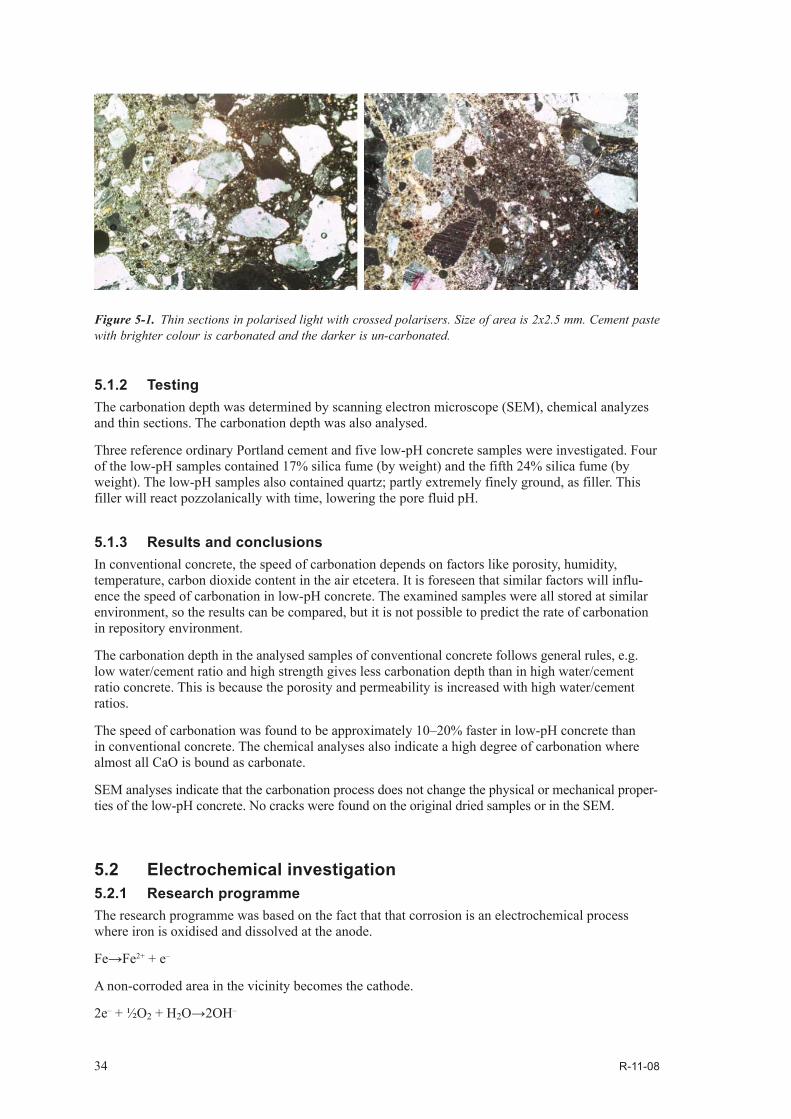
5.1.2 TestingThe carbonation depth was determined by scanning electron microscope (SEM), chemical analyzes and thin sections. The carbonation depth was also analysed.
Three reference ordinary Portland cement and five low-pH concrete samples were investigated. Four of the low-pH samples contained 17% silica fume (by weight) and the fifth 24% silica fume (by weight). The low-pH samples also contained quartz; partly extremely finely ground, as filler. This filler will react pozzolanically with time, lowering the pore fluid pH.
5.1.3 Results and conclusionsIn conventional concrete, the speed of carbonation depends on factors like porosity, humidity, temperature, carbon dioxide content in the air etcetera. It is foreseen that similar factors will influ-ence the speed of carbonation in low-pH concrete. The examined samples were all stored at similar environment, so the results can be compared, but it is not possible to predict the rate of carbonation in repository environment.
The carbonation depth in the analysed samples of conventional concrete follows general rules, e.g. low water/cement ratio and high strength gives less carbonation depth than in high water/cement ratio concrete. This is because the porosity and permeability is increased with high water/cement ratios.
The speed of carbonation was found to be approximately 10–20% faster in low-pH concrete than in conventional concrete. The chemical analyses also indicate a high degree of carbonation where almost all CaO is bound as carbonate.
SEM analyses indicate that the carbonation process does not change the physical or mechanical proper-ties of the low-pH concrete. No cracks were found on the original dried samples or in the SEM.
5.2 Electrochemical investigation5.2.1 Research programmeThe research programme was based on the fact that that corrosion is an electrochemical process where iron is oxidised and dissolved at the anode.
Fe→Fe2+ + e–
A non-corroded area in the vicinity becomes the cathode.
2e– + ½O2 + H2O→2OH–
Figure 5-1. Thin sections in polarised light with crossed polarisers. Size of area is 2x2.5 mm. Cement paste with brighter colour is carbonated and the darker is un-carbonated.
R-11-08 35
An ionic current transports iron in the pore solution and an electronic current in the iron transport the electrons.
By measuring the changes in the electrochemical process it is possible to find out when the corrosion starts and the rate of corrosion. The ionic current reflects the extent of the corrosion process and is measured through the polarisation resistance, not directly. It is a complicated process and several methods with reference electrodes were used.
Most tests were done using an instrument called RapiCor, which uses galvanostatic pulse technique for measuring polarisation resistance. In order to validate the results, this method was supplemented with another method measuring the half-cell potential with an embedded electrode.
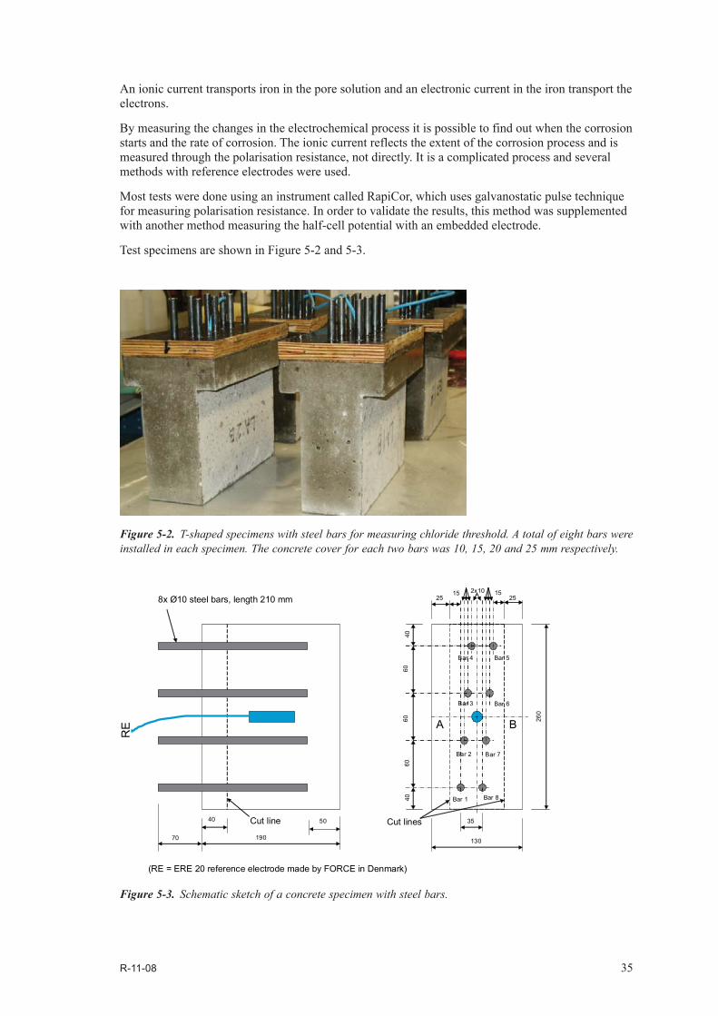
Test specimens are shown in Figure 5-2 and 5-3.
Figure 5-2. T-shaped specimens with steel bars for measuring chloride threshold. A total of eight bars were installed in each specimen. The concrete cover for each two bars was 10, 15, 20 and 25 mm respectively.
Figure 5-3. Schematic sketch of a concrete specimen with steel bars.
2515 2x10 15
25
130
260
6060
6040
40
RE
8x Ø10 steel bars, length 210 mm
190
40 50
70
35
(RE = ERE 20 reference electrode made by FORCE in Denmark)
Cut line Cut lines
Bar 1
Bar 2
Bar 3
Bar 4 Bar 5
Bar 6
Bar 7
Bar 8
A B

36 R-11-08
5.2.2 TestingIn short the test set-up was as follows:
1. Two types of concrete specimens were cast, conventional concrete and low-pH concrete respectively. Reinforcement bars were embedded with different concrete cover.
2. Moisture profiles were estimated for pre-conditioning of the specimens, Figure 5-4.
3. After drying out, the specimens were immersed in chloride salt solution. Two concentrations were used; 3 and 10% (by weight), Figure 5-5.
4. At the end of the programme the chloride content at different depths in the specimens was analysed.
5. The half-cell potential was monitored through a reference electrode embedded in the concrete.
6. The corrosion measurement instrument RapiCor was applied at certain intervals.
7. At the end of the tests, the specimens were dismantled and the corrosion products on the steel bars were inspected visually.
Figure 5-4. Example of estimated moisture profiles in the specimens. LA = low-pH concrete Courtesy of Björn Lagerblad and Tang Luping, CBI.
Figure 5-5. Chloride exposure. Courtesy of Björn Lagerblad and Tang Luping, CBI.
0
10
20
30
40
50
60
70
80
90
0 20 40 60 80 100
x, mm
Ref 1A Ref 1BRef 2A Ref 2BLA 1A LA 1BLA 2A LA 2B
w(x,
t) - w0
, kg/
m3

R-11-08 37
5.2.3 Results and conclusionsThe chloride profile at the end of the test programme showed that the low-pH concrete absorbed less chloride ions than the conventional concrete. This is because the low-pH concrete is less porous than ordinary concrete due to large amount of fine aggregate.
Most measurements were done with RapiCor, but the results from the method with embedded reference electrode and half-cell monitoring gave similar results, showing that:
Corrosion is initiated earlier in low-pH concrete than in conventional concrete.
The rate of corrosion in low-pH concrete is less than in conventional concrete.
The steel bars in the low-pH concrete showed more negative half-cell potential than those in conventional concrete.
The low-pH concrete had a significantly higher resistivity than conventional concrete, indicating differences in electronic conductivity in the pore solutions.
The rate of corrosion diminishes with concrete cover thickness, but steel bars at the same depth in the low-pH concrete always began to corrode earlier than those in the conventional concrete.
In the macro-cell measurements, the corrosion current between two reinforcement bars is measured. The results showed that the corrosion current between the two bars was distinctively less in the low-pH concrete, presumably due to high resistivity in the concrete. This was supported by the resistivity measurements made with RapiCor.
The visual examination after the tests showed corrosion as expected from the electric measurements.
The conclusions from the electrochemical investigation are that the pH in low-pH concrete is high enough to prevent steel corrosion, but the concrete should be dense and homogeneous. If exposed to chloride ions, steel in the low-pH concrete will start to corrode earlier but with a slower rate than in conventional concrete.
5.3 Field exposure at Äspö HRL5.3.1 Research programmeThe formula used to cast the specimens is based on the mix shown in Table 5-1.
A total of 24 concrete specimens were cast as below:
• 12 specimens low-pH concrete:– 4 untreated specimens (without chlorides).– 4 specimens with 2% (by weight of the binder) cast in chlorides.– 4 specimens exposed to a 10% chloride solution for three months before field exposure.
• 12 specimens conventional concrete:– 4 untreated specimens (without chlorides).– 4 specimens with 2% (by weight of the binder) cast in chlorides.– 4 specimens exposed to a 10% chloride solution for three months before field exposure.
Each specimen contained three steel bars, Figure 5-6 and Figure 5-7. Each steel bar, with a diameter of 20 mm and a length of 200 mm, was carefully cleaned and weighed with an accuracy of a thousandth gram.

38 R-11-08
The specimens were then placed for field exposure in an open container in niche NASA2715 at the Äspö HRL, Figure 5-8.
5.3.2 TestingAfter 515–525 days of field exposure, a total of six specimens, one of each type, was taken out for investigation. The corrosion rate was determined by weighing the mass lost by corrosion. The steel bars were photographed, Figure 5-9, and the pit depths were measured with a pit depth dial gauge. Shallow pits were measured with an optical microscope with calibrated focus knob.
Figure 5-6. Specimen dimensions.
Figure 5-7. Mould and steel bars on supports before casting.

R-11-08 39
Figure 5-8. Container in Äspö HRL with samples corrosion tests.
Figure 5-9. Example of photos of exposed steel bars, photographed from two sides.

40 R-11-08
5.3.3 Results and conclusionsField exposure results obtained are summarized in Table 5-2.
The steel bars in untreated specimens, concrete with no chlorides, had an average corrosion rate of 12.0 µm/year for low-pH concrete and 12.5 µm/year for conventional concrete. The corrosion rates obtained are considered high as passive steel in concrete is regarded to have a corrosion rate of about 1 µm/year. Heterogeneous exposure conditions might have had an effect.
The steel bars in concrete exposed to a 10% chloride solution for three months before field exposure had an average corrosion rate of 12.3 µm/year for low-pH concrete and 37.9 µm/year for conven-tional concrete. The same corrosion rate has thus been obtained for low-pH concrete with immersed in chlorides and without chlorides. This is a clear indication of the fact that low-pH concrete being denser than conventional concrete; three months exposure in a 10% chloride solution has not been enough for the chloride to reach the steel bars in the low-pH concrete.
The steel bars in concrete with cast-in chlorides had an average corrosion rate of 22.1 µm/year for low-pH concrete and 15.2 µm/year for conventional concrete. Tests the coming years will show evo-lution in corrosion rate with time. Will the corrosion in low-pH concrete with immersed in chlorides increase with time, i.e. when chlorides reach the steel bars, or will the corrosion rates decrease with time etc?
Similar results are obtained if using depth of corrosion pits as a measure of corrosion, i.e. same results with an without immersed in chlorides for low-pH concrete and pit depths of the same order of magnitude for the two concrete types with cast-in chloride respectively.
In summary, it was found that the steel in low-pH specimens containing cast in chlorides, were slightly more corroded than in conventional concrete. At the same time low-pH concrete has a lower ability to absorb water, thus prolonging the corrosion initiating time.
Table 5-2. Average corrosion rates and maximum pit depths measured after the Äspö field exposure.
Low-pH concrete
Sample (steel bar no) Chloride Corrosion rate, average for three steel bars [µm/year]
Deepest pit depths for respective steel bar [µm]
1 (1, 2, 3) Exposed to chloride solution
12.3 ± 0.3 20, 35, 20
5 (14, 15, 16) None 12.0 ± 0.1 25, 40, 2510 (26, 27, 28) 2% cast-in 22.1 ± 0.4 800, 400, 600
Conventional concrete14 (38, 39, 40) Exposed to chloride
solution37.9 ± 5.5 2,200, 2,800, 1,700
18 (50, 51 52) None 12.5 ± 0.5 30, 40, 6522 (62, 63, 64) 2% cast-in 15.2 ± 2.7 800, 700, 600

R-11-08 41
6 Results and conclusions
Installation of rock bolts, shotcreting and reinforcement steel corrosion in low-pH cementitious materials have been investigated. The results are promising and it is foreseen that low-pH cementi-tious materials can be used in a final repository. Further evaluation of results will continue for approximately 10 years.
6.1 Rock boltsSo far, installation of rock bolts in low-pH grout was successful and does not indicate any particular difficulties. Over coring of the bolts and inspection of the cores in the coming years will show if there have been any problems when filling the holes with grout or if there are any durability problems.
6.2 ShotcreteThe laboratory tests at Älvkarleby and the following field test at Äspö HRL proved that it is possible to use low-pH shotcrete. Slump values of approximately 21–24 cm at the beginning of the shotcret-ing and an air content around 14% in the fresh concrete gives a shotcrete that is possible to spray.
The fibre rebound in the shotcrete laboratory tests was unacceptable high, almost 50%, but was less than 20% in the following field test. A normal figure for rebound in conventional shotcrete is in the range of 10–30% of the fibre content. This high rebound can be a result of several parameters like equipment, nozzle angle, substrate, distance between nozzle and area of application, experience of the nozzle man and mix design of the concrete.
The results of the bond tests between shotcrete and rock show normal values, with a mean value of 0.8 MPa, varying between 0.31 and 1.53 MPa.
6.3 Steel corrosionThe expected increased risk for steel corrosion in low-pH concrete was investigated via carbonation, electrochemical investigation and field exposure at Äspö HRL.
6.3.1 Carbonation and electrochemical investigationThe speed of carbonation was found to be approximately 10–20% faster in low-pH concrete than in conventional concrete. The chemical composition of a low-pH concrete indicates a faster carbona-tion in low-pH concrete compared to conventional concrete. The chemical analyses also indicate a high degree of carbonation where almost all CaO is bound as carbonate. SEM analyses indicate that the carbonation process does not change the physical or mechanical properties of the low-pH concrete. No cracks were found on the original dried samples or in the SEM.
The chloride profile at the end of the test programme showed that the low-pH concrete absorbed less chloride ions than the conventional concrete. This is because the low-pH concrete becomes less porous than ordinary concrete with time.
42 R-11-08
The main results from the electrochemical investigation are:
• Corrosion is initiated earlier in low-pH concrete than in conventional concrete.
• The rate of corrosion in low-pH concrete is less than in conventional concrete.
• The steel bars in the low-pH concrete showed more negative half-cell potential than those in conventional concrete.
• The low-pH concrete had a significantly higher resistivity than conventional concrete, indicating differences in electronic conductivity in the pore solutions.
• The rate of corrosion diminishes with concrete cover thickness, but steel bars at the same depth in the low-pH concrete always began to corrode earlier than those in the conventional concrete.
The visual examination after the electrochemical tests showed corrosion as expected from the electric measurements.
The conclusions from the electrochemical investigation are that the pH in low-pH concrete similar to the SKB concrete (approximately pH 11) is high enough to prevent steel corrosion, but the concrete should be dense and homogeneous. If exposed to chloride ions, steel in the low-pH concrete will start to corrode earlier but with a slower rate than in conventional concrete.
6.3.2 Field exposure at Äspö HRLThe first results from the field exposure experiments show that:
• Steel bars in untreated specimens, i.e. concrete with no chlorides, had approximately the same corrosion rate in the two concrete types.
• Corrosion rates in untreated specimens, i.e. concrete without chlorides, are considered high. Heterogeneous exposure conditions might have had an effect.
• Steel bars in concrete with cast in chlorides had approximately 50% higher corrosion rate in low-pH concrete than in conventional concrete. Corrosion pit depths did not show similar behav-iour; corrosion pit depths of the same order of magnitude were found both in conventional and in low-pH concrete. Tests in the coming years will show if this is because corrosion in low-pH concrete starts earlier than in conventional concrete.
• Steel bars in concrete exposed to a 10% chloride solution for three months before field exposure had an average first year corrosion rate that was approximately three times higher in conventional concrete than in low-pH concrete. This can be explained by the fact that that low-pH concrete is denser than ordinary concrete. Consequently the chlorides have most likely not yet reached the steel bars.
In summary, it was found that steel in low-pH specimens containing cast-in chlorides, is slightly more corrosive than conventional concrete. At the same time low-pH concrete has a lower ability to absorb water, thus reducing risks for chloride induced corrosion.
To determine if the lower corrosion rates for low-pH concrete with absorbed chlorides compared to conventional concrete with absorbed chlorides are due to slower chloride transport velocity, the chloride concentration of the concretes must be assessed.
6.4 ConclusionsIn summary, from a design point of view, all results so far indicate that low-pH cementitious materials are suitable for use in a final repository.

R-11-08 43
7 References
SKB’s (Svensk Kärnbränslehantering AB) publications can be found at www.skb.se/publications.
Bodén A, Sievänen U, 2005. Low-pH injection grout for deep repositories. Summary report from a co-operation project between NUMO (Japan), Posiva (Finland) and SKB (Sweden). SKB R-05-40, Svensk Kärnbränslehantering AB.
Funehag J, 2008. Injektering av TASS-tunneln. Delresultat t o m september 2008. SKB R-08-123, Svensk Kärnbränslehantering AB.
Holmgren J, Alemo J, Skarendahl Å, 1997. Stålfiberbetong för bergförstärkning – provning och värdering (Steel fibre sprayed concrete for rock strengthening – testing and evaluation) (in Swedish). CBI report 1997:3, Swedish Cement and Concrete Research Institute.
Vogt C, Lagerblad B, Wallin K, Baldy F, Jonasson J-E, 2009. Low pH self compacting concrete for deposition tunnel plugs. SKB R-09-07, Svensk Kärnbränslehantering AB.