DEVELOPMENT OF RELIABILITY ASSESSMENT SOFTWARE · PDF fileDEVELOPMENT OF RELIABILITY...
10
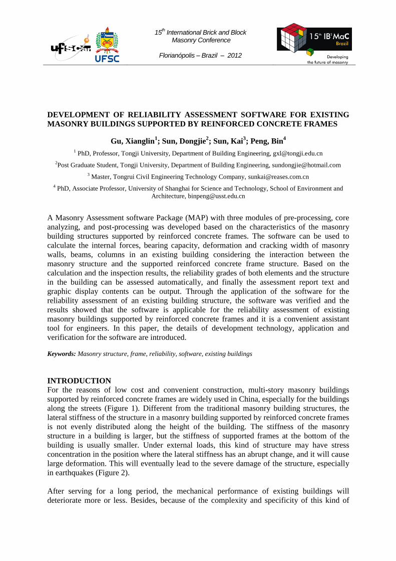
15 th International Brick and Block Masonry Conference Florianópolis – Brazil – 2012 DEVELOPMENT OF RELIABILITY ASSESSMENT SOFTWARE FOR EXISTING MASONRY BUILDINGS SUPPORTED BY REINFORCED CONCRETE FRAMES Gu, Xianglin 1 ; Sun, Dongjie 2 ; Sun, Kai 3 ; Peng, Bin 4 1 PhD, Professor, Tongji University, Department of Building Engineering, [email protected] 2 Post Graduate Student, Tongji University, Department of Building Engineering, [email protected] 3 Master, Tongrui Civil Engineering Technology Company, [email protected] 4 PhD, Associate Professor, University of Shanghai for Science and Technology, School of Environment and Architecture, [email protected] A Masonry Assessment software Package (MAP) with three modules of pre-processing, core analyzing, and post-processing was developed based on the characteristics of the masonry building structures supported by reinforced concrete frames. The software can be used to calculate the internal forces, bearing capacity, deformation and cracking width of masonry walls, beams, columns in an existing building considering the interaction between the masonry structure and the supported reinforced concrete frame structure. Based on the calculation and the inspection results, the reliability grades of both elements and the structure in the building can be assessed automatically, and finally the assessment report text and graphic display contents can be output. Through the application of the software for the reliability assessment of an existing building structure, the software was verified and the results showed that the software is applicable for the reliability assessment of existing masonry buildings supported by reinforced concrete frames and it is a convenient assistant tool for engineers. In this paper, the details of development technology, application and verification for the software are introduced. Keywords: Masonry structure, frame, reliability, software, existing buildings INTRODUCTION For the reasons of low cost and convenient construction, multi-story masonry buildings supported by reinforced concrete frames are widely used in China, especially for the buildings along the streets (Figure 1). Different from the traditional masonry building structures, the lateral stiffness of the structure in a masonry building supported by reinforced concrete frames is not evenly distributed along the height of the building. The stiffness of the masonry structure in a building is larger, but the stiffness of supported frames at the bottom of the building is usually smaller. Under external loads, this kind of structure may have stress concentration in the position where the lateral stiffness has an abrupt change, and it will cause large deformation. This will eventually lead to the severe damage of the structure, especially in earthquakes (Figure 2). After serving for a long period, the mechanical performance of existing buildings will deteriorate more or less. Besides, because of the complexity and specificity of this kind of
Transcript of DEVELOPMENT OF RELIABILITY ASSESSMENT SOFTWARE · PDF fileDEVELOPMENT OF RELIABILITY...
15th International Brick and Block
Masonry Conference
Florianópolis – Brazil – 2012
DEVELOPMENT OF RELIABILITY ASSESSMENT SOFTWARE FOR EXISTING
MASONRY BUILDINGS SUPPORTED BY REINFORCED CONCRETE FRAMES
Gu, Xianglin1; Sun, Dongjie
2; Sun, Kai
3; Peng, Bin
4
1 PhD, Professor, Tongji University, Department of Building Engineering, [email protected]
2Post Graduate Student, Tongji University, Department of Building Engineering, [email protected]
3 Master, Tongrui Civil Engineering Technology Company, [email protected]
4 PhD, Associate Professor, University of Shanghai for Science and Technology, School of Environment and
Architecture, [email protected]
A Masonry Assessment software Package (MAP) with three modules of pre-processing, core
analyzing, and post-processing was developed based on the characteristics of the masonry
building structures supported by reinforced concrete frames. The software can be used to
calculate the internal forces, bearing capacity, deformation and cracking width of masonry
walls, beams, columns in an existing building considering the interaction between the
masonry structure and the supported reinforced concrete frame structure. Based on the
calculation and the inspection results, the reliability grades of both elements and the structure
in the building can be assessed automatically, and finally the assessment report text and
graphic display contents can be output. Through the application of the software for the
reliability assessment of an existing building structure, the software was verified and the
results showed that the software is applicable for the reliability assessment of existing
masonry buildings supported by reinforced concrete frames and it is a convenient assistant
tool for engineers. In this paper, the details of development technology, application and
verification for the software are introduced.
Keywords: Masonry structure, frame, reliability, software, existing buildings
INTRODUCTION
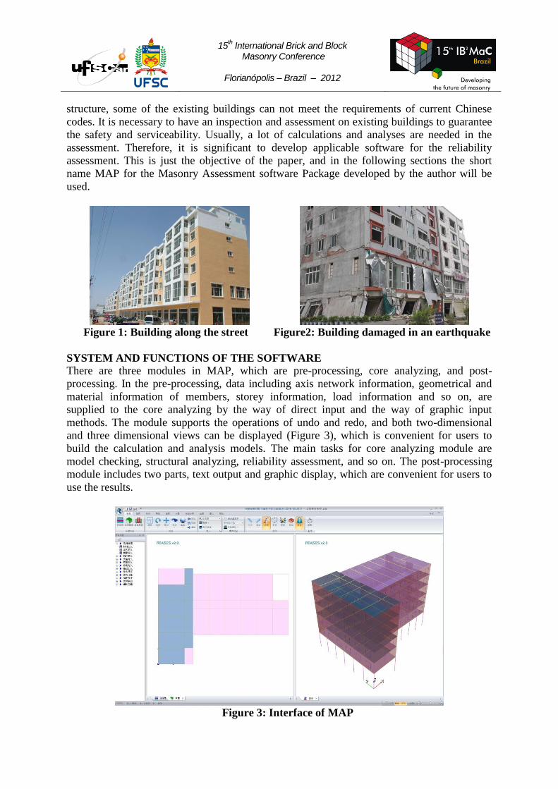
For the reasons of low cost and convenient construction, multi-story masonry buildings
supported by reinforced concrete frames are widely used in China, especially for the buildings
along the streets (Figure 1). Different from the traditional masonry building structures, the
lateral stiffness of the structure in a masonry building supported by reinforced concrete frames
is not evenly distributed along the height of the building. The stiffness of the masonry
structure in a building is larger, but the stiffness of supported frames at the bottom of the
building is usually smaller. Under external loads, this kind of structure may have stress
concentration in the position where the lateral stiffness has an abrupt change, and it will cause
large deformation. This will eventually lead to the severe damage of the structure, especially
in earthquakes (Figure 2).
After serving for a long period, the mechanical performance of existing buildings will
deteriorate more or less. Besides, because of the complexity and specificity of this kind of
15th International Brick and Block
Masonry Conference
Florianópolis – Brazil – 2012
structure, some of the existing buildings can not meet the requirements of current Chinese
codes. It is necessary to have an inspection and assessment on existing buildings to guarantee
the safety and serviceability. Usually, a lot of calculations and analyses are needed in the
assessment. Therefore, it is significant to develop applicable software for the reliability
assessment. This is just the objective of the paper, and in the following sections the short
name MAP for the Masonry Assessment software Package developed by the author will be
used.
Figure 1: Building along the street Figure2: Building damaged in an earthquake
SYSTEM AND FUNCTIONS OF THE SOFTWARE
There are three modules in MAP, which are pre-processing, core analyzing, and post-
processing. In the pre-processing, data including axis network information, geometrical and
material information of members, storey information, load information and so on, are
supplied to the core analyzing by the way of direct input and the way of graphic input
methods. The module supports the operations of undo and redo, and both two-dimensional
and three dimensional views can be displayed (Figure 3), which is convenient for users to
build the calculation and analysis models. The main tasks for core analyzing module are
model checking, structural analyzing, reliability assessment, and so on. The post-processing
module includes two parts, text output and graphic display, which are convenient for users to
use the results.
Figure 3: Interface of MAP
15th International Brick and Block
Masonry Conference
Florianópolis – Brazil – 2012
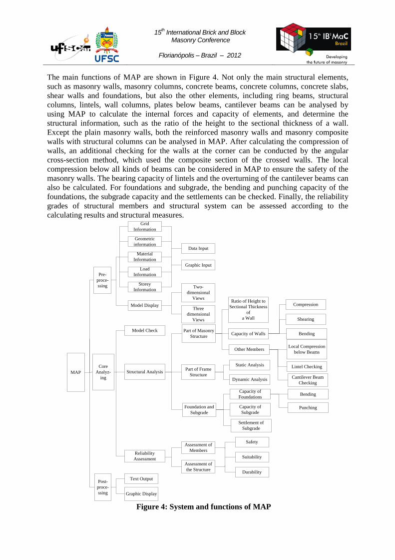
The main functions of MAP are shown in Figure 4. Not only the main structural elements,
such as masonry walls, masonry columns, concrete beams, concrete columns, concrete slabs,
shear walls and foundations, but also the other elements, including ring beams, structural
columns, lintels, wall columns, plates below beams, cantilever beams can be analysed by
using MAP to calculate the internal forces and capacity of elements, and determine the
structural information, such as the ratio of the height to the sectional thickness of a wall.
Except the plain masonry walls, both the reinforced masonry walls and masonry composite
walls with structural columns can be analysed in MAP. After calculating the compression of
walls, an additional checking for the walls at the corner can be conducted by the angular
cross-section method, which used the composite section of the crossed walls. The local
compression below all kinds of beams can be considered in MAP to ensure the safety of the
masonry walls. The bearing capacity of lintels and the overturning of the cantilever beams can
also be calculated. For foundations and subgrade, the bending and punching capacity of the
foundations, the subgrade capacity and the settlements can be checked. Finally, the reliability
grades of structural members and structural system can be assessed according to the
calculating results and structural measures.
MAP
Pre-
proce-
ssing
Core
Analyz-
ing
Grid
Information
Geometric
information
Material
Information
Load
Information
Storey
Information
Model Check
Structural Analysis
Reliability
Assessment
Text Output
Graphic Display
Post-
proce-
ssing
Model Display
Data Input
Graphic Input
Two-
dimensional
Views
Three
dimensional
Views
Part of Masonry
Structure
Part of Frame
Structure
Foundation and
Subgrade
Assessment of
Members
Assessment of
the Structure
Safety
Suitability
Durability
Ratio of Height to
Sectional Thickness
of
a Wall
Capacity of Walls
Other Members
Static Analysis
Dynamic Analysis
Capacity of
Foundations
Capacity of
Subgrade
Settlement of
Subgrade
Compression
Shearing
Bending
Local Compression
below Beams
Lintel Checking
Cantilever Beam
Checking
Bending
Punching
Figure 4: System and functions of MAP
15th International Brick and Block
Masonry Conference
Florianópolis – Brazil – 2012
KEY TECHNOLOGY IN THE SOFTWARE
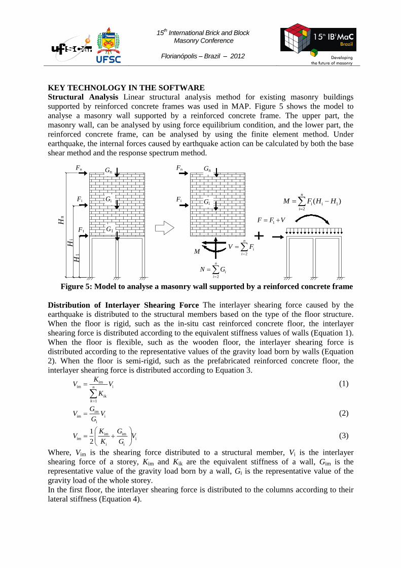
Structural Analysis Linear structural analysis method for existing masonry buildings
supported by reinforced concrete frames was used in MAP. Figure 5 shows the model to
analyse a masonry wall supported by a reinforced concrete frame. The upper part, the
masonry wall, can be analysed by using force equilibrium condition, and the lower part, the
reinforced concrete frame, can be analysed by using the finite element method. Under
earthquake, the internal forces caused by earthquake action can be calculated by both the base
shear method and the response spectrum method.
Hn
Hi
H1
Figure 5: Model to analyse a masonry wall supported by a reinforced concrete frame
Distribution of Interlayer Shearing Force The interlayer shearing force caused by the
earthquake is distributed to the structural members based on the type of the floor structure.
When the floor is rigid, such as the in-situ cast reinforced concrete floor, the interlayer
shearing force is distributed according to the equivalent stiffness values of walls (Equation 1).
When the floor is flexible, such as the wooden floor, the interlayer shearing force is
distributed according to the representative values of the gravity load born by walls (Equation
2). When the floor is semi-rigid, such as the prefabricated reinforced concrete floor, the
interlayer shearing force is distributed according to Equation 3.
imim i
ik
1
n
k
KV V
K
(1)
imim i
i
GV V
G (2)
im imim i
i i
1
2
K GV V
K G
(3)
Where, Vim is the shearing force distributed to a structural member, Vi is the interlayer
shearing force of a storey, Kim and Kik are the equivalent stiffness of a wall, Gim is the
representative value of the gravity load born by a wall, Gi is the representative value of the
gravity load of the whole storey.
In the first floor, the interlayer shearing force is distributed to the columns according to their
lateral stiffness (Equation 4).
Fn
Fi
F1
Gn
Gi
G1
Fn
Fi
Gn
Gi
i
2
n
i
V F
i
2
n
i
N G
i i 1
2
( )n
i
M F H H
M
1F F V

15th International Brick and Block
Masonry Conference
Florianópolis – Brazil – 2012
imrimr im
imt
1
s
t
KV V
K
(4)
Where, Vimr is the shearing force distributed to the calculating unit, Kimr and Kimt are the
equivalent stiffnesses of the calculating unit, s is the number of the calculating units
belonging to the entire storey.
Seismic Force of the Supported Frame The seismic forces of the supported frame include
the shearing force and the overturning moment which are shown in Figure 5. Because the
lateral stiffness of the upper masonry wall is larger than that of the lower supported frame, the
shearing force born by the supported frame should be multiplied by an amplifying coefficient
between 1.2 and 1.5 which is determined by k
, where γk is the ratio of the lateral stiffness
of the masonry wall to that of the supported frame. The overturning moment is generated by
the horizontal forces applied on the upper masonry wall. Knowing the overturning moment,
the axial forces in supported columns can be easily calculated. For example, when the
earthquake direction is parallel to the X axis in Figure 6, the vertical force of a supported
column is:
y i i i
i2
k y0k k k
1
( )
[ ( ) ]n
k
M E A X aN
E I A X a
(5)
Where, My is the overturning moment of the frame in X direction; Ei or Ek is the elastic
modulus of a column, Ai or Ak is the sectional area of a column, Xi or Xk is the coordinate of
the center of a column in X direction; a is the coordinate of the storey center in X direction,
Iy0k is the moment of inertia of a column.
Y
X
x
yy
x
a
b
Figure 6: Coordinate system of a structure
Adjustment of Internal Forces of Wall Beams The beams of the frame and the supported
wall can be considered as a composite structural member. Because of the arch effect of the
wall, the value of moment and shearing force in top frame beams can be reduced both at the
span middle and the support end, and longitudinal tensile forces should be added to the beams
correspondingly. Therefore, the beams are actually subjected to axial tension and bending.
Assessment of Structures The safety of elements is assessed based on four items of bearing
capacity, structural measures, unsuitable displacement and cracking status. There are four
15th International Brick and Block
Masonry Conference
Florianópolis – Brazil – 2012
grades (au to du) for each item, which can be determined based on the reliability analysis
results. For example, the grade of bearing capacity of structural members, including the
concrete and masonry members, can be calculated according to Table 1, where R is the value
of bearing capacity, S is the value of internal force, γR is the partial coefficient, γ0 is the
coefficient of importance. The minimum grade among four items is regarded as the safety
grade of a structural member. The suitability of a structural element is assessed based on three
items of displacement, non-stress cracking, and air-slake. Also the minimum grade is regarded
as the suitability grade for a structural member. Finally, the smaller value between the safety
and suitability grade is taken as the reliability grade for a structural member. If we take into
account the performance deterioration of structural members with time, the durability of a
structural member can also be assessed. After finishing the assessment for all the structural
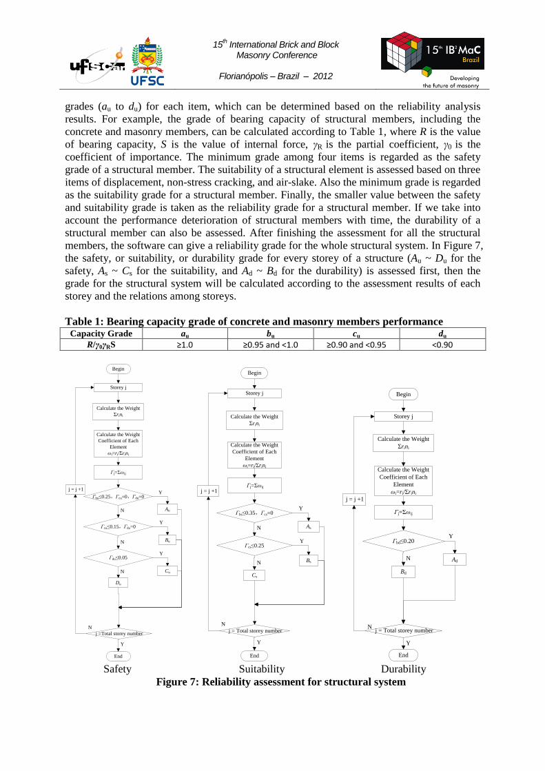
members, the software can give a reliability grade for the whole structural system. In Figure 7,
the safety, or suitability, or durability grade for every storey of a structure (Au ~ Du for the
safety, As ~ Cs for the suitability, and Ad ~ Bd for the durability) is assessed first, then the
grade for the structural system will be calculated according to the assessment results of each
storey and the relations among storeys.
Table 1: Bearing capacity grade of concrete and masonry members performance Capacity Grade au bu cu du
R/γ0γRS ≥1.0 ≥0.95 and <1.0 ≥0.90 and <0.95 <0.90
Begin
Calculate the Weight
Coefficient of Each
Element
ωi=ri/Σrini
Γj=Σωij
N
N
Du
Au
Bu
Cu
Y
Y
End
j =Total storey number
N
Y
Calculate the Weight
Σrini
Storey j
Γbu≤0.25,Γcu=0,Γdu=0
Γcu≤0.15,Γdu=0
Γdu≤0.05
N
Y
j = j +1
Begin
Calculate the Weight
Coefficient of Each
Element
ωi=ri/Σrini
Γj=Σωij
N
Cs
As
Bs
Y
Y
End
j = Total storey number
N
Y
Calculate the Weight
Σrini
Storey j
Γbs≤0.35,Γcs=0
Γcs≤0.25
N
j = j +1
Begin
Calculate the Weight
Coefficient of Each
Element
ωi=ri/Σrini
Γj=Σωij
Bd
Ad
Y
End
j = Total storey numberN
Y
Calculate the Weight
Σrini
Storey j
Γbd≤0.20
N
j = j +1
Safety Suitability Durability
Figure 7: Reliability assessment for structural system
15th International Brick and Block
Masonry Conference
Florianópolis – Brazil – 2012
APPLICATION OF THE SOFTWARE
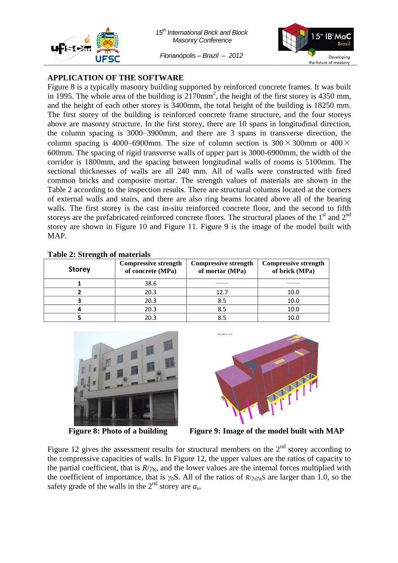
Figure 8 is a typically masonry building supported by reinforced concrete frames. It was built
in 1995. The whole area of the building is 2170mm2, the height of the first storey is 4350 mm,
and the height of each other storey is 3400mm, the total height of the building is 18250 mm.
The first storey of the building is reinforced concrete frame structure, and the four storeys
above are masonry structure. In the first storey, there are 10 spans in longitudinal direction,
the column spacing is 3000–3900mm, and there are 3 spans in transverse direction, the
column spacing is 4000–6900mm. The size of column section is 300×300mm or 400×600mm. The spacing of rigid transverse walls of upper part is 3000-6900mm, the width of the
corridor is 1800mm, and the spacing between longitudinal walls of rooms is 5100mm. The
sectional thicknesses of walls are all 240 mm. All of walls were constructed with fired
common bricks and composite mortar. The strength values of materials are shown in the
Table 2 according to the inspection results. There are structural columns located at the corners
of external walls and stairs, and there are also ring beams located above all of the bearing
walls. The first storey is the cast in-situ reinforced concrete floor, and the second to fifth
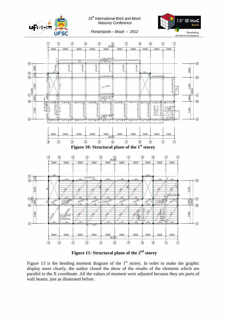
storeys are the prefabricated reinforced concrete floors. The structural planes of the 1st and 2
nd
storey are shown in Figure 10 and Figure 11. Figure 9 is the image of the model built with
MAP.
Table 2: Strength of materials
Storey Compressive strength
of concrete (MPa)
Compressive strength
of mortar (MPa)
Compressive strength
of brick (MPa)
1 38.6 —— ——
2 20.3 12.7 10.0
3 20.3 8.5 10.0
4 20.3 8.5 10.0
5 20.3 8.5 10.0
Figure 8: Photo of a building Figure 9: Image of the model built with MAP
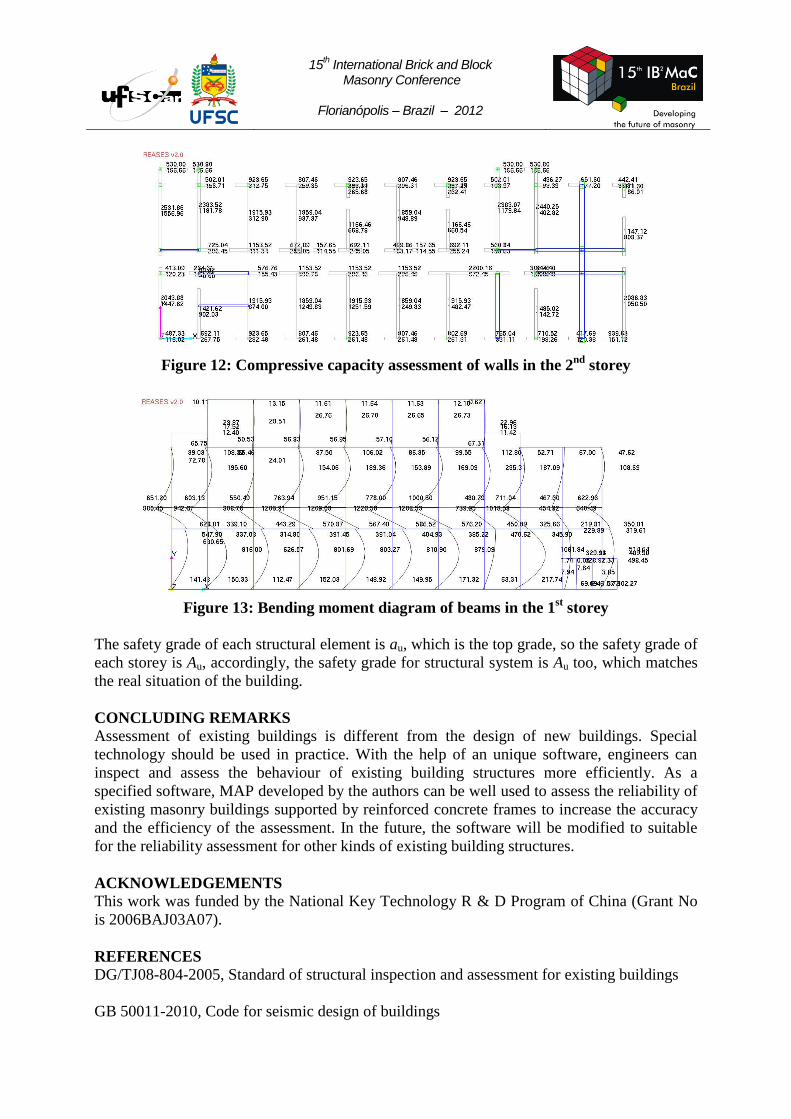
Figure 12 gives the assessment results for structural members on the 2nd
storey according to
the compressive capacities of walls. In Figure 12, the upper values are the ratios of capacity to
the partial coefficient, that is R/γR, and the lower values are the internal forces multiplied with
the coefficient of importance, that is γ0S. All of the ratios of R/γ0γRS are larger than 1.0, so the
safety grade of the walls in the 2nd
storey are au.
15th International Brick and Block
Masonry Conference
Florianópolis – Brazil – 2012
LL2(10) 250x800
LL1(10) 300x700
LL1(10) 300x700
LL1(6) 300x700 LL1(2) 300x700
KJ-
2(2
) 4
00
x1
20
0
KJ-
1(3
) 4
00
x1
20
0
KJ-
1(3
) 4
00
x1
20
0
KJ-
1(3
) 4
00
x1
20
0
KJ-
1(3
) 4
00
x1
20
0
KJ-
1(3
) 4
00
x1
20
0
KJ-
1(3
) 4
00
x1
20
0
KJ-
1(3
) 4
00
x1
20
0
KJ-
2(2
) 4
00
x1
20
0
KJ-
2(2
) 4
00
x1
20
0
KJ-
2(2
) 4
00
x1
20
0
QL
QL
25
0x
40
0
LL3(6) 250x1000
25
0x
40
0
25
0x
40
0
25
0x
40
0
25
0x
40
0
25
0x
40
0
25
0x
40
0
QL
QL
L11 240x400
L1
2 2
40
x3
00
YP1
YP
2
51
00
18
00
51
00
40
00
16
00
0
3000 3900 3900 3900 3900 3900 3900 3000 3600 330036300
3000 3900 3900 3900 3900 3900 3900 3000 3600 330036300
51
00
18
00
51
00
12
00
28
00
16
00
0
4.160
Figure 10: Structural plane of the 1
st storey
GL GL GL GL GL GL
GL GL GL GL GL
GL GL GL GL GL GL
GL
GL
GL GL
GL
GL
GL
GL
GL
GL GL GL
GL
GL GL GL GL GL GL
QL
GL
L22(2) 250x700
L22(2) 250x700
L21(2
) 400x950
L23 3
00x750
L24 250x350
QL 240x240
QL
QL
QL
QL
GL
GL
GL
弯)
L25 150x300 YZB
YZB
YZB
YZB
YZB Y
ZB
YZB
YZ
B
YZB
YZB
YZB
YZB
YZB
YZB
YZ
B
YZB
B2(
100) B
3(10
0)
B1(100)B1(100)
B1(100)B1(100)
B1(100)
B1(100)
B1(100)B1
B1(100) B1
Z
Z
Z
51
00
18
00
51
00
120
00
3000 3900 3900 3900 3900 3900 3900 3000 3600 330036300
3000 3900 3900 3900 3900 3900 3900 3000 3600 330036300
51
00
18
00
51
00
12
00
132
00
7.560
Figure 11: Structural plane of the 2nd
storey
Figure 13 is the bending moment diagram of the 1st storey. In order to make the graphic
display more clearly, the author closed the show of the results of the elements which are
parallel to the X coordinate. All the values of moment were adjusted because they are parts of
wall beams, just as illustrated before.
15th International Brick and Block
Masonry Conference
Florianópolis – Brazil – 2012
Figure 12: Compressive capacity assessment of walls in the 2
nd storey
Figure 13: Bending moment diagram of beams in the 1
st storey
The safety grade of each structural element is au, which is the top grade, so the safety grade of
each storey is Au, accordingly, the safety grade for structural system is Au too, which matches
the real situation of the building.
CONCLUDING REMARKS
Assessment of existing buildings is different from the design of new buildings. Special
technology should be used in practice. With the help of an unique software, engineers can
inspect and assess the behaviour of existing building structures more efficiently. As a
specified software, MAP developed by the authors can be well used to assess the reliability of
existing masonry buildings supported by reinforced concrete frames to increase the accuracy
and the efficiency of the assessment. In the future, the software will be modified to suitable
for the reliability assessment for other kinds of existing building structures.
ACKNOWLEDGEMENTS
This work was funded by the National Key Technology R & D Program of China (Grant No
is 2006BAJ03A07).
REFERENCES
DG/TJ08-804-2005, Standard of structural inspection and assessment for existing buildings
GB 50011-2010, Code for seismic design of buildings
15th International Brick and Block
Masonry Conference
Florianópolis – Brazil – 2012
Gu, X L, Chen, S J, and Zhang, W P. “Practical method of assessing reliability of structural
system of existing buildings.” Structural Engineers. 23, 2007, 12-17. (in Chinese)
Gu, X.L., Sun, D.J. ”Development and Application of Reliability Assessment Software for
Historic Masonry Structures”. Advanced Materials Research, Part 2., 2010, pp 1271-1276.
Gu, X L, Xu, Y, and Zhang, W P. “Safety analysis of elements in existing buildings.” Journal
of Building Structures. 25, 2004, 117-122. (in Chinese)
Li S B, Wang, J G, and Xie, H C. “Development of reliability assessment software for
existing buildings.” Journal of Chongqing Polytechnic College. 17, 2002, 13-14. (in Chinese)
Lu X L, Zhou, D Y, and Li, S M. “Theories and instances of seismic design for building
structures.” Shanghai, China: Tongji University Press, 2002, 93-111. (in Chinese)