Development of Programmable Relay Switch Using...
9
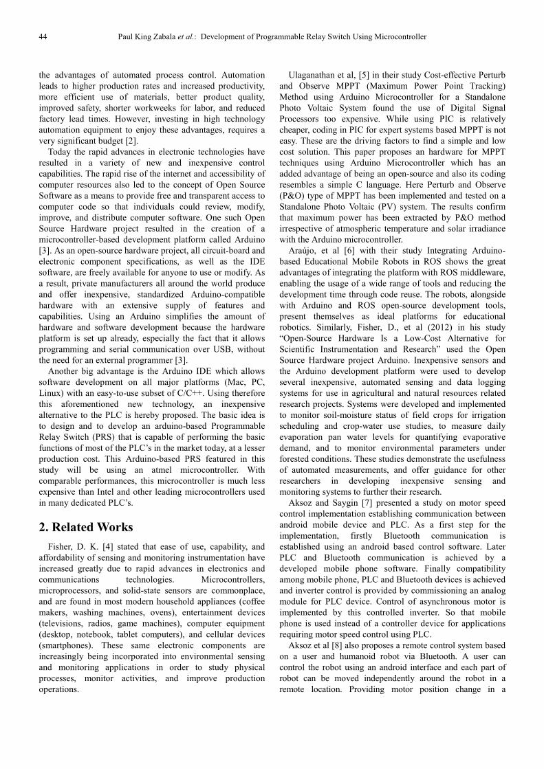
American Journal of Remote Sensing 2018; 5(5): 43-51 http://www.sciencepublishinggroup.com/j/ajrs doi: 10.11648/j.ajrs.20170505.11 ISSN: 2328-5788 (Print); ISSN: 2328-580X (Online) Development of Programmable Relay Switch Using Microcontroller Paul Zabala 1 , Mary Charlemaine Abas 2 , Patrick Cerna 3 1 Department of Mechatronics Technology, Cebu Technological University, Cebu City, Philippines 2 Department of Electronics Technology, Federal Technological Institute - University, Addis Ababa, Ethiopia 3 Department of Information Technology, Federal Technological Institute - University, Addis Ababa, Ethiopia Email address: To cite this article: Paul Zabala, Mary Charlemaine Abas, Patrick Cerna. Development of Programmable Relay Switch Using Microcontroller. American Journal of Remote Sensing. Vol. 5, No. 5, 2017, pp. 43-51. doi: 10.11648/j.ajrs.20170505.11 Received: December 28, 2017; Accepted: January 17, 2018; Published: February 5, 2018 Abstract: Today the rapid advances in electronic technologies have resulted in a variety of new and inexpensive control capabilities. The rapid rise of the internet and accessibility of computer resources also led to the concept of Open Source Software as a means to provide free and transparent access to computer code so that individuals could review, modify, improve, and distribute computer software. One such Open Source Hardware project resulted in the creation of a microcontroller-based development platform called Arduino. The main objective of this research is to develop an arduino- based PRS to be manufactured by small and Medium Enterprises (SME) in Ethiopia. Specifically, it seeks to answer the (1) What are the technical requirements in the development of the PRS (2) What are the basic functional capabilities of the PRS in terms of Combinational Logic Functions and Sequential Control Functions and (3) What is the acceptability level of PRS as perceived by experts in terms of functionality, reliability, usability, maintainability, aesthetics and safety. The study used descriptive experimental methods of research utilizing laboratory techniques and adopted scholarly questionnaires. The methods were appropriate to determine the physical design, components, tools, functions and features needed in the development of the project. Those were extremely useful in the development of the actual circuit, final parts selection, and software programming to ensure a robust design. Two experiment were tested namely Combinational Logic Functions and Sequential Control Functions using the Programmable Relay Switch and it generates acceptable results by passing all the testing condition. It was concluded that the PRS product model has standard functional capabilities comparable to most standard PLC’s in the market and it is a cheaper but efficient alternative. It can also be constructed from commercially available parts. Moreover, it can be used for actual industrial applications or as a training module in teaching industrial automation or mechatronics courses. Keywords: Programmable Relay Switch, Programmable Logic Controller, Microcontroller, Arduino, IoT, Remote Sensing 1. Introduction Research and development in the field of automation and control for industrial applications has increased rapidly in the recent years. Along with these developments, new manpower requirements (i.e. new skills and expertise) also arise. It is very important therefore for the education sector to keep up with the latest technologies in the field. However, offering industrial automation and control courses in universities is a major challenge. This is because courses that include instrumentations and automation technologies need a significant budget for the acquisition of such expensive modules and high technology equipment for training. Programmable Logic Controllers (PLC’s), in particular, the most widely used control equipment in industrial automation and control, are too expensive for the students to integrate in their automation and control projects. Looking at the industrial manufacturing side today, the sheer number of PLC applications is enormous nowadays. According to Research and Markets [1], the world’s largest market research store, global programmable logic controller (PLC) forecasts market to grow at a CAGR of 5.57% during the period 2017-2021. Manufacturers today are well aware of
Transcript of Development of Programmable Relay Switch Using...
American Journal of Remote Sensing 2018; 5(5): 43-51
http://www.sciencepublishinggroup.com/j/ajrs
doi: 10.11648/j.ajrs.20170505.11
ISSN: 2328-5788 (Print); ISSN: 2328-580X (Online)
Development of Programmable Relay Switch Using Microcontroller
Paul Zabala1, Mary Charlemaine Abas
2, Patrick Cerna
3
1Department of Mechatronics Technology, Cebu Technological University, Cebu City, Philippines 2Department of Electronics Technology, Federal Technological Institute - University, Addis Ababa, Ethiopia 3Department of Information Technology, Federal Technological Institute - University, Addis Ababa, Ethiopia
Email address:
To cite this article: Paul Zabala, Mary Charlemaine Abas, Patrick Cerna. Development of Programmable Relay Switch Using Microcontroller. American
Journal of Remote Sensing. Vol. 5, No. 5, 2017, pp. 43-51. doi: 10.11648/j.ajrs.20170505.11
Received: December 28, 2017; Accepted: January 17, 2018; Published: February 5, 2018
Abstract: Today the rapid advances in electronic technologies have resulted in a variety of new and inexpensive control
capabilities. The rapid rise of the internet and accessibility of computer resources also led to the concept of Open Source
Software as a means to provide free and transparent access to computer code so that individuals could review, modify,
improve, and distribute computer software. One such Open Source Hardware project resulted in the creation of a
microcontroller-based development platform called Arduino. The main objective of this research is to develop an arduino-
based PRS to be manufactured by small and Medium Enterprises (SME) in Ethiopia. Specifically, it seeks to answer the (1)
What are the technical requirements in the development of the PRS (2) What are the basic functional capabilities of the PRS in
terms of Combinational Logic Functions and Sequential Control Functions and (3) What is the acceptability level of PRS as
perceived by experts in terms of functionality, reliability, usability, maintainability, aesthetics and safety. The study used
descriptive experimental methods of research utilizing laboratory techniques and adopted scholarly questionnaires. The
methods were appropriate to determine the physical design, components, tools, functions and features needed in the
development of the project. Those were extremely useful in the development of the actual circuit, final parts selection, and
software programming to ensure a robust design. Two experiment were tested namely Combinational Logic Functions and
Sequential Control Functions using the Programmable Relay Switch and it generates acceptable results by passing all the
testing condition. It was concluded that the PRS product model has standard functional capabilities comparable to most
standard PLC’s in the market and it is a cheaper but efficient alternative. It can also be constructed from commercially
available parts. Moreover, it can be used for actual industrial applications or as a training module in teaching industrial
automation or mechatronics courses.
Keywords: Programmable Relay Switch, Programmable Logic Controller, Microcontroller, Arduino, IoT, Remote Sensing
1. Introduction
Research and development in the field of automation and
control for industrial applications has increased rapidly in the
recent years. Along with these developments, new manpower
requirements (i.e. new skills and expertise) also arise. It is
very important therefore for the education sector to keep up
with the latest technologies in the field. However, offering
industrial automation and control courses in universities is a
major challenge. This is because courses that include
instrumentations and automation technologies need a
significant budget for the acquisition of such expensive
modules and high technology equipment for training.
Programmable Logic Controllers (PLC’s), in particular, the
most widely used control equipment in industrial automation
and control, are too expensive for the students to integrate in
their automation and control projects.
Looking at the industrial manufacturing side today, the
sheer number of PLC applications is enormous nowadays.
According to Research and Markets [1], the world’s largest
market research store, global programmable logic controller
(PLC) forecasts market to grow at a CAGR of 5.57% during
the period 2017-2021. Manufacturers today are well aware of
44 Paul King Zabala et al.: Development of Programmable Relay Switch Using Microcontroller
the advantages of automated process control. Automation
leads to higher production rates and increased productivity,
more efficient use of materials, better product quality,
improved safety, shorter workweeks for labor, and reduced
factory lead times. However, investing in high technology
automation equipment to enjoy these advantages, requires a
very significant budget [2].
Today the rapid advances in electronic technologies have
resulted in a variety of new and inexpensive control
capabilities. The rapid rise of the internet and accessibility of
computer resources also led to the concept of Open Source
Software as a means to provide free and transparent access to
computer code so that individuals could review, modify,
improve, and distribute computer software. One such Open
Source Hardware project resulted in the creation of a
microcontroller-based development platform called Arduino
[3]. As an open-source hardware project, all circuit-board and
electronic component specifications, as well as the IDE
software, are freely available for anyone to use or modify. As
a result, private manufacturers all around the world produce
and offer inexpensive, standardized Arduino-compatible
hardware with an extensive supply of features and
capabilities. Using an Arduino simplifies the amount of
hardware and software development because the hardware
platform is set up already, especially the fact that it allows
programming and serial communication over USB, without
the need for an external programmer [3].
Another big advantage is the Arduino IDE which allows
software development on all major platforms (Mac, PC,
Linux) with an easy-to-use subset of C/C++. Using therefore
this aforementioned new technology, an inexpensive
alternative to the PLC is hereby proposed. The basic idea is
to design and to develop an arduino-based Programmable
Relay Switch (PRS) that is capable of performing the basic
functions of most of the PLC’s in the market today, at a lesser
production cost. This Arduino-based PRS featured in this
study will be using an atmel microcontroller. With
comparable performances, this microcontroller is much less
expensive than Intel and other leading microcontrollers used
in many dedicated PLC’s.
2. Related Works
Fisher, D. K. [4] stated that ease of use, capability, and
affordability of sensing and monitoring instrumentation have
increased greatly due to rapid advances in electronics and
communications technologies. Microcontrollers,
microprocessors, and solid-state sensors are commonplace,
and are found in most modern household appliances (coffee
makers, washing machines, ovens), entertainment devices
(televisions, radios, game machines), computer equipment
(desktop, notebook, tablet computers), and cellular devices
(smartphones). These same electronic components are
increasingly being incorporated into environmental sensing
and monitoring applications in order to study physical
processes, monitor activities, and improve production
operations.
Ulaganathan et al, [5] in their study Cost-effective Perturb
and Observe MPPT (Maximum Power Point Tracking)
Method using Arduino Microcontroller for a Standalone
Photo Voltaic System found the use of Digital Signal
Processors too expensive. While using PIC is relatively
cheaper, coding in PIC for expert systems based MPPT is not
easy. These are the driving factors to find a simple and low
cost solution. This paper proposes an hardware for MPPT
techniques using Arduino Microcontroller which has an
added advantage of being an open-source and also its coding
resembles a simple C language. Here Perturb and Observe
(P&O) type of MPPT has been implemented and tested on a
Standalone Photo Voltaic (PV) system. The results confirm
that maximum power has been extracted by P&O method
irrespective of atmospheric temperature and solar irradiance
with the Arduino microcontroller.
Araújo, et al [6] with their study Integrating Arduino-
based Educational Mobile Robots in ROS shows the great
advantages of integrating the platform with ROS middleware,
enabling the usage of a wide range of tools and reducing the
development time through code reuse. The robots, alongside
with Arduino and ROS open-source development tools,
present themselves as ideal platforms for educational
robotics. Similarly, Fisher, D., et al (2012) in his study
“Open-Source Hardware Is a Low-Cost Alternative for
Scientific Instrumentation and Research” used the Open
Source Hardware project Arduino. Inexpensive sensors and
the Arduino development platform were used to develop
several inexpensive, automated sensing and data logging
systems for use in agricultural and natural resources related
research projects. Systems were developed and implemented
to monitor soil-moisture status of field crops for irrigation
scheduling and crop-water use studies, to measure daily
evaporation pan water levels for quantifying evaporative
demand, and to monitor environmental parameters under
forested conditions. These studies demonstrate the usefulness
of automated measurements, and offer guidance for other
researchers in developing inexpensive sensing and
monitoring systems to further their research.
Aksoz and Saygin [7] presented a study on motor speed
control implementation establishing communication between
android mobile device and PLC. As a first step for the
implementation, firstly Bluetooth communication is
established using an android based control software. Later
PLC and Bluetooth communication is achieved by a
developed mobile phone software. Finally compatibility
among mobile phone, PLC and Bluetooth devices is achieved
and inverter control is provided by commissioning an analog
module for PLC device. Control of asynchronous motor is
implemented by this controlled inverter. So that mobile
phone is used instead of a controller device for applications
requiring motor speed control using PLC.
Aksoz et al [8] also proposes a remote control system based
on a user and humanoid robot via Bluetooth. A user can
control the robot using an android interface and each part of
robot can be moved independently around the robot in a
remote location. Providing motor position change in a
American Journal of Remote Sensing 2017; 5(5): 43-51 45
mechanical system and automatic controlling of the data from
the measuring instrument reduce process time and reduce loss
of labor. The automatic controlling of the data from the
measuring instrument is supplied with microprocessor
Many of these recently conducted researches mentioned
above show that the arduino board, with its open-source
platform, prove to be more flexible, easy-to-use and inexpensive
for artists, designers, hobbyists, researchers, and anyone
interested in creating interactive objects or environments.
3. Materials and Methods
3.1. Research Design and Methodology
The study used descriptive experimental methods of
research utilizing laboratory techniques and adopted
scholarly questionnaires. The methods were appropriate to
determine the physical design, components, tools, functions
and features needed in the development of the project. Those
were extremely useful in the development of the actual
circuit, final parts selection, and software programming to
ensure a robust design.
Thus, to test the operational functionality of the design,
laboratory check sheets were utilized based on the
operational requirements. The reliability of the design was
further tested using environmental and accelerated testing.
Survey questionnaires were developed to seek the perception
of the experts/end-users regarding the product’s functionality,
reliability, usability, maintainability, proficiency, aesthetics,
and safety.
3.2. Materials Used in the Study
The proposed utilize Arduino Microcontroller with its
accompanying shields, sensors, modules and switches among
others as shown in Table 1.
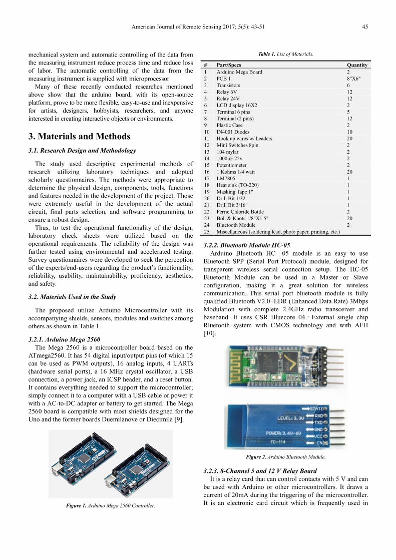
3.2.1. Arduino Mega 2560
The Mega 2560 is a microcontroller board based on the
ATmega2560. It has 54 digital input/output pins (of which 15
can be used as PWM outputs), 16 analog inputs, 4 UARTs
(hardware serial ports), a 16 MHz crystal oscillator, a USB
connection, a power jack, an ICSP header, and a reset button.
It contains everything needed to support the microcontroller;
simply connect it to a computer with a USB cable or power it
with a AC-to-DC adapter or battery to get started. The Mega
2560 board is compatible with most shields designed for the
Uno and the former boards Duemilanove or Diecimila [9].
Figure 1. Arduino Mega 2560 Controller.
Table 1. List of Materials.
# Part/Specs Quantity
1 Arduino Mega Board 2
2 PCB 1 8"X6"
3 Transistors 6
4 Relay 6V 12
5 Relay 24V 12
6 LCD display 16X2 2
7 Terminal 6 pins 5
8 Terminal (2 pins) 12
9 Plastic Case 2
10 IN4001 Diodes 10
11 Hook up wires w/ headers 20
12 Mini Switches 8pin 2
13 104 mylar 2
14 1000uF 25v 2
15 Potentiometer 2
16 1 Kohms 1/4 watt 20
17 LM7805 1
18 Heat sink (TO-220) 1
19 Masking Tape 1" 1
20 Drill Bit 1/32" 1
21 Drill Bit 3/16" 1
22 Ferric Chloride Bottle 2
23 Bolt & Knots 1/8"X1.5" 20
24 Bluetooth Module 2
25 Miscellaneous (soldering lead, photo paper, printing, etc.)
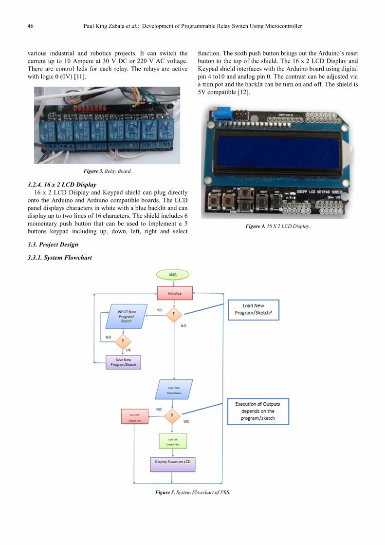
3.2.2. Bluetooth Module HC-05
Arduino Bluetooth HC‐05 module is an easy to use
Bluetooth SPP (Serial Port Protocol) module, designed for
transparent wireless serial connection setup. The HC-05
Bluetooth Module can be used in a Master or Slave
configuration, making it a great solution for wireless
communication. This serial port bluetooth module is fully
qualified Bluetooth V2.0+EDR (Enhanced Data Rate) 3Mbps
Modulation with complete 2.4GHz radio transceiver and
baseband. It uses CSR Bluecore 04‐External single chip
Rluetooth system with CMOS technology and with AFH
[10].
Figure 2. Arduino Bluetooth Module.
3.2.3. 8-Channel 5 and 12 V Relay Board
It is a relay card that can control contacts with 5 V and can
be used with Arduino or other microcontrollers. It draws a
current of 20mA during the triggering of the microcontroller.
It is an electronic card circuit which is frequently used in
46 Paul King Zabala et al.: Development of Programmable Relay Switch Using Microcontroller
various industrial and robotics projects. It can switch the
current up to 10 Ampere at 30 V DC or 220 V AC voltage.
There are control leds for each relay. The relays are active
with logic 0 (0V) [11].
Figure 3. Relay Board.
3.2.4. 16 x 2 LCD Display
16 x 2 LCD Display and Keypad shield can plug directly
onto the Arduino and Arduino compatible boards. The LCD
panel displays characters in white with a blue backlit and can
display up to two lines of 16 characters. The shield includes 6
momentary push button that can be used to implement a 5
buttons keypad including up, down, left, right and select
function. The sixth push button brings out the Arduino’s reset
button to the top of the shield. The 16 x 2 LCD Display and
Keypad shield interfaces with the Arduino board using digital
pin 4 to10 and analog pin 0. The contrast can be adjusted via
a trim pot and the backlit can be turn on and off. The shield is
5V compatible [12].
Figure 4. 16 X 2 LCD Display.
3.3. Project Design
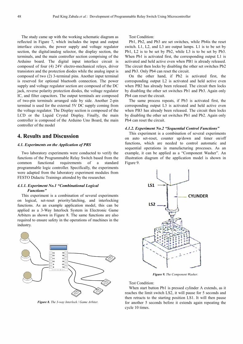
3.3.1. System Flowchart
Figure 5. System Flowchart of PRS.

American Journal of Remote Sensing 2017; 5(5): 43-51 47
As shown in Figure 5, the system flowchart upon powering
on the PRS, the main microcontroller which is the arduino
board, starts to initialize by loading the bootloader code. If
the bootloader does not receive a particular sequence of bytes
over the serial port, then the processor jumps to the program
section to load whatever is already in program memory.
Normally, the arduino reads the predefined input pins and
then executes the output by turning the predefined output
pins high or low depending on the sketch/code. The status of
inputs and outputs can also be optionally displayed on the
LCD display and the loop is repeated endlessly. If however,
the bootloader receives a unique sequence from its serial
port, then the byte stream or new code is programmed into
the flash. By using the Arduino Integrated Development
Environment, one can load a new sketch/code to the PRS.
After the loading of the sketch to the arduino board, it will
then re-initializes and starts executing again the new
sketch/code.
3.3.2. Block Diagram
The Block Diagramas reflected in Figure 6 is composed of
the main Arduino board, the input, and the output interface
circuits. The Input interface circuits are composed of the 24V
Input relays, the analog input terminals for analog sensors
and the optional Bluetooth input Module for wireless control.
The output interface circuits are also composed of the
transistor drivers for driving the output relays, and the LCD
display module for optional display of input and output
status.
Figure 6. Block Diagram of PRS.
3.3.3. Schematic Diagram
Figure 7. Schematic Diagram of PRS.
48 Paul King Zabala et al.: Development of Programmable Relay Switch Using Microcontroller
The study came up with the working schematic diagram as
reflected in Figure 7, which includes the input and output
interface circuits, the power supply and voltage regulator
section, the digital/analog selector, the display section, the
terminals, and the main controller section comprising of the
Arduino board. The digital input interface circuit is
composed of four (4) 24V electro-mechanical relays, driver
transistors and the protection diodes while the analog input is
composed of two (2) 3-terminal pins. Another input terminal
is reserved for optional bluetooth connection. The power
supply and voltage regulator section are composed of the DC
jack, reverse polarity protection diodes, the voltage regulator
IC, and filter capacitors. The output terminals are composed
of two-pin terminals arranged side by side. Another 2-pin
terminal is used for the external 5V DC supply coming from
the voltage regulator. The Display section is composed of the
LCD or the Liquid Crystal Display. Finally, the main
controller is composed of the Arduino Uno Board, the main
controller of the model
4. Results and Discussion
4.1. Experiments on the Application of PRS
Two laboratory experiments were conducted to verify the
functions of the Programmable Relay Switch based from the
common functional requirements of a standard
programmable logic controller. Specifically, the experiments
were adapted from the laboratory experiment modules from
FESTO Didactic Trainings attended by the researcher.
4.1.1. Experiment No.1 “Combinational Logical
Functions”
This experiment is a combination of several experiments
on logical, set-reset priority/latching, and interlocking
functions. As an example application model, this can be
applied as a 3-Way Interlock System in Electronic Game
Arbiters as shown in Figure 8. The same functions are also
required to ensure safety in the operations of machines in the
industry.
Figure 8. The 3-way Interlock / Game Arbiter.
Test Condition:
Pb1, Pb2, and Pb3 are set switches, while Pb4is the reset
switch. L1, L2, and L3 are output lamps. L1 is to be set by
Pb1, L2 is to be set by Pb2, while L3 is to be set by Pb3.
When Pb1 is activated first, the corresponding output L1 is
activated and held active even when PB1 is already released.
The circuit then locks by disabling the other set switches Pb2
and Pb3. Only Pb4 can reset the circuit.
On the other hand, if Pb2 is activated first, the
corresponding output L2 is activated and held active even
when PB2 has already been released. The circuit then locks
by disabling the other set switches Pb1 and Pb3. Again only
Pb4 can reset the circuit.
The same process repeats, if Pb3 is activated first, the
corresponding output L3 is activated and held active even
when PB3 has already been released. The circuit then locks
by disabling the other set switches Pb1 and Pb2. Again only
Pb4 can reset the circuit.
4.1.2. Experiment No.2 “Sequential Control Functions”
This experiment is a combination of several experiments
on auto set-reset, counter up/down and timer on/off
functions, which are needed to control automatic and
sequential operations in manufacturing processes. As an
example, it can be applied as a “Component Washer”. An
illustration diagram of the application model is shown in
Figure 9.
Figure 9. The Component Washer.
Test Condition:
When start button Pb1 is pressed cylinder A extends, as it
reaches the limit switch LS2, it will pause for 5 seconds and
then retracts to the starting position LS1. It will then pause
for another 5 seconds before it extends again repeating the
cycle 10 times.

American Journal of Remote Sensing 2017; 5(5): 43-51 49
After the 10th cycle, a buzzer activates for 2 seconds while
a light activates permanently until another process starts by
pressing Pb1 again. Another push button Pb2 stops the
process, returns the cylinder to the starting position, and
automatically resets the counter.
4.2. Acceptability on the Application of PRS
The study adopts purposive sampling method with the
target respondents will be the experts and prospective users
from both the academe and SME of the final prototype. To
determine the acceptability of the project, this study were
utilizing a researcher-made questionnaire based on the “The
Hierarchy of Design Needs” by William Lidwell, et. al.
(Table 2) adapted from the “Hierarchy of Needs” by
Abraham Maslow. The questionnaire was based on the
perception of the respondents regarding functionality,
reliability, usability, aesthetics, and safety of the
Programmable Relays as shown on Table 2. The electronic
components and circuit diagrams were identified firs and the
circuits assembled were experimentally tested in the
laboratory according to its requirements. The operational
features were also be tested during the programming phase.
After the testing and demonstrations, the questionnaires were
administered to the respondents to seek for their perceptions
toward the prototype.
Table 2. Results of the Acceptability Testing.
Criteria Frequency (%)
Functionality 90
Reliability 72
Usability 88
Maintainability 52
Efficiency 87
Aesthetics 52.2
Safety 70
4.2.1. Functionality
On the acceptability level of the PRS with regards to its
design and quality, the first to be determined was the
functionality of the prototype. The functions identifiedin this
study are the most common PLC functions that are utilized in
most industrial applications. These are also the same
functions that every student must learn when taking up PLC
programming courses. In Maslow’s Hierarchy of Needs
translated to Designing the most basic need of a good design
is Functionality. An average of 90 percent of the respondents
had rated highly functional. The remaining 10 percent had
rated moderately functional. This means that a great majority
of the respondents perceived the PRSas having functions
comparable to that of a standard programmable logic
controller.
4.2.2. Reliability
Once a design has met functional needs, it can move up to
the next level in the design hierarchy: Reliability. The design
should not only work but it must work again and again
consistently. In the 8 dimensions of quality by David Garvin,
reliable designs successfully perform specified functions for
a specified period of time. Also, 72 percent of the
respondents rated “highly reliable” while the remaining 24
percent, rated “moderately reliable”. Majority of the
respondents therefore, believe that the product can work
consistently for a longer period of time.
4.2.3. Usability
Another feature was rated on the prototype, which is
“usability”. Usability is the 3rd level in Maslow’s Hierarchy
of Needstranslated to design. The following questions are
based on the basic question: How easily can users
accomplish basic tasks with this product88 percent of the
respondents rated “highly usable” while the remaining 12
percent rated “moderately usable”. The rating shows thata
good majority of the respondents find the PRSeasy to use.
4.2.4. Maintainability
Maintainability, also known as serviceability is the speed,
courtesy, competence, and ease of repair. It is fifth on the list
in the Eight Dimensions of Quality by David Garvin52
percent of the respondents rated the product to be
“maintainable”, while the remaining 48 percent, rated it to be
“moderately maintainable”. Although majority of the
respondents believe the prototypeis easy to repair slightly
lower rating of the prototype as compared to the other
features is due to the very compact placement of parts inside
the packaging box.
4.2.5. Efficiency
Efficient products empower people to do more and to do
better at a shorter period of time. 87 percent of the
respondents rated “highly efficient”, while the remaining 13
percent rated “moderately efficient”. After all, the PRS is
made to be efficient because it simplifies the amount of
hardware and software development. The hardware platform
is set up already, especially the fact that it allows
programming and serial communication over USB, without
the need for an external programmer. The survey results also
clearly show these advantages.
4.2.6. Aesthetics
Aesthetics is seventh on the list in David Garvin’s Eight
Dimensions of Quality. It generally refers to how a product
looks, feels, sounds, tastes, or smells. It is largely based on a
personal judgment and individual preference. 52.2 percent of
the respondents rated the aesthetics of the prototype to be
“highly acceptable”, while the remaining 47.8percent rated
“moderately acceptable”. This implies that majority of the
respondents find the prototype to have a good external design
or appearance.
4.2.7. Safety
In addition to being easy to use and good in appearance,
the design must be forgiving. Consequences for simple
mistakes should not be dire. 70 percent of the respondents
rated “highly safe”, while the remaining 30 percent rated
“moderately safe”. Most respondents believe that the product
is safe to use. In fact, it is using a low voltage power supply
of only 5V DC.

50 Paul King Zabala et al.: Development of Programmable Relay Switch Using Microcontroller
5. Summary
The following were the most significant findings of this
study:
5.1. On the Technical Requirements
The study came up with the working schematic diagram,
which includes the interface circuits, the power supply and
voltage regulator section (Figure 1), the PCB component
layout (Figure 2) and the Bill of materials shown in Table 1
and the Tools and equipment Needed in the Construction of
the PRS also shown in Table 3. All the materials needed for
the construction of the prototype were either purchased
locally or on-line.
5.2. On the Applications of the PRS
The study adapted and modified the laboratory
experiments of the FESTO Didactic PLC training and came
up with the combinational logical functional experiment
which, as a sample application, it can be applied as a 3 –way
interlock system for quiz bowl competitions or for gaming
purposes (Figure 3). Another experiment performed is the
sequential control function experiment, which as an example,
it can also be applied as a component washer in
manufacturing industries (Figure 4). Appendix A shows the
laboratory sheets with their results.
5.3. On the Acceptability of the PRS Model
5.3.1. Functionality
The data revealed that the prototype is highly functional as
perceived by the experts. And as tested in the laboratory, the
PRS is capable of performing combinational logical control
and sequential operations control.
5.3.2. Reliability
As evaluated by the respondents, the data revealed that the
prototype is highly reliable. During the testing, the prototype
also performed and complied with the functional
requirements.
5.3.3. Usability
Although the PRS is not using the usual ladder language
for a PLC, the data revealed that the respondents perceived
the PRS to be highly usable.
5.3.4. Maintainability
Although only 52 percent of the respondents found the
PRS to be highly maintainable, while 48 percent rated it to be
just moderately maintainable, the average mean shows
however, that the product still falls under the rating of
“highly maintainable”.
5.3.5. Efficiency
One of the highest ratings of the PRS model by the
respondents is the efficiency. The respondents found it to be
highly efficient as it simplifies the amount of hardware and
software development. The hardware platform is set up
already, especially the fact that it allows programming and
serial communication over USB, without the need for an
external programmer.
5.3.6. Aesthetics
Although aesthetics of the product received a slightly low
rating because of its customized packaging, the mean average
still shows a highly acceptable rating by the respondents.
5.3.7. Safety
With the safety features of the product model, it is
perceived to be highly safe to use by the respondents. The
model could be utilized as a training module in the academe
or as an applied controller in industrial manufacturing
operations.
6. Conclusion
Based on the above findings, it was concluded that the
PRS product model has standard functional capabilities
comparable to most standard PLC’s in the market and it is a
cheaper but efficient alternative. It can also be constructed
from commercially available parts. Moreover, it can be used
for actual industrial applications or as a training module in
teaching industrial automation or mechatronics courses.
It is recommended that the PRS model be adapted and
utilized for industrial automation applications. It can also
used for instructional purposes in institutions offering
industrial automation courses. It is also recommended further
that, should it be applied in actual industrial use, a long-term
study be conducted to check the durability and life span of
the design model.
References
[1] Research and Markets (2017). Global Programmable Logic Controller (PLC) Market 2017-2021 With Mitsubishi Electric, OMRON, Rockwell Automation, Schneider Electric & Siemens Dominating. Accessed October 2, 2017.
[2] Britannica (2017). Advantages and disadvantages of automation. Encyclopedia Britannica. Retrieved in https://www.britannica.com/technology/automation/Advantages-and-disadvantages-of-automation. Accessed March 5, 2017.
[3] Fisher, D. K., Gould, P. J. (2012). Open-Source Hardware Is a Low-Cost Alternative for Scientific Instrumentation and Research. Modern Instrumentation. Vol 1 (2).
[4] Fisher, D. K. (2014). Rapid Deployment of Internet-Connected Environmental Monitoring Devices, Advances in Internet Things. Vol (4). 46–54.
[5] Ulaganathan, M. K. D., Saravanan, C., &Chitranjan, O. R. (2014). Cost-effective Perturb and Observe MPPT Method using Arduino Microcontroller for a Standalone Photo Voltaic System, 8 (1), 24–28.
[6] Araujo, A., Portugal, D., Couceiro, M. S., Rocha, R. P. (2015). Integrating Arduino-Based Educational Mobile Robots in ROS. Journal of Intelligent and Robotic Systems. Vol 77. pp 281-298.

American Journal of Remote Sensing 2017; 5(5): 43-51 51
[7] Aksoz, A., Engin, S., & Dursun, M. (2016). The Implementation of Controlled Humanoid Robot with Android. Journal of Automation and Control Engineering. Vol4 (3), 225–228. doi:10.18178/joace.4.3.225-228.
[8] Aksoz, A., & Saygin, A. L. I. (2015). Android mobile devices based automation system. International Journal of Electrical, Electronics and Data Communication. Vol, (3), Issue 3. pp 5–11.
[9] Arduino (2016). Arduino Mega 2560 Specification. Retrieved from https://www.arduino.cc/en/main/arduinoBoardMega2560. Accessed March 2017.
[10] ePro Labs (2017). Bluetooth Module HC-05. Retrieved from https://wiki.eprolabs.com/index.php?title=Bluetooth_Module_HC-05
[11] Ultimate Robot Part (2017). 12 V 8-Channel Relay Board. Retrieved from http://www.jsumo.com/12v-8-channel-relay-board. Accessed August 15, 2017.
[12] OSEPP (2017). 16 X 2 LCD Display and Keypad Shield. Retrieved from https://www.osepp.com/electronic-modules/shields/45-16-2-lcd-display-keypad-shield#. Access August 15, 2017.