Development of primary suspension damping control system ... · the system and a secondary...
12
Challenge D: A world of services for passengers 1/12 Development of primary suspension damping control system for suppressing vertical bending vibration of railway vehicle car body Y. SUGAHARA, N. WATANABE, T. TAKIGAMI, R. KOGANEI Railway Technical Research Institute, Tokyo, Japan Abstract Suppression of vertical bending vibration is essential to improve ride comfort on railway vehicles. For this purpose, a primary suspension damping force control system is being developed. This paper describes the composition of the system and reports on the results from vehicle running tests on some Shinkansen lines using actual Shinkansen vehicles fitted with the developed variable primary vertical dampers. The results of these tests demonstrate that this system is effective in reducing vertical vibration acceleration in the first bending mode of the car body and improves ride comfort. This paper also reports on results from vibration excitation tests on a railway vehicle equipped with this control system on a rolling stock test plant to verify its effectiveness in vibration suppression even in the presence of passengers. In addition, a progress report is also given on developments to the system and a secondary suspension damping control system. 1. Introduction Horizontal ride comfort on recently developed Shinkansen vehicles in Japan has been markedly improved by virtue of vibration control systems, such as semi-active and active suspension [1, 2]. As a result, passengers now tend to sense vertical vibration more than horizontal vibration. Therefore, vertical vibration suppression of car body is required to improve ride comfort more. In the vertical direction, car body elastic vibration, which has a natural frequency of around 8-12 Hz, needs to be suppressed (particularly the first bending mode vibration) [3]. This is because the natural frequency is close to 4-8 Hz: a vertical vibration to which humans are sensitive [4]. The first bending mode vibration frequently becomes a problem because Shinkansen vehicles in Japan must be as light-weight as possible to achieve high running speed while being able to accommodate track and environmental constraints [5]. Therefore, various methods for suppressing the first bending mode vibration have so far been proposed. The conventionally used methods of suppressing bending vibration in car bodies include dissipating vibration energy by introducing some damping materials [6] or dynamic dampers [7], by utilizing car-body-bogie dynamic interaction [8], and directly applying a damping force to the car body by attaching piezoelectric elements [9, 10]. Vibration control can also be achieved by attaching actuators or variable dampers to the secondary suspension [11, 12]. Attaching active mass dampers to the car body and actuators to the secondary suspension can be used as methods to simultaneously suppress bending and rigid-body-mode vibrations in car bodies [13]. Although some of these methods are being evaluated in running tests, there are still relatively few reports on any significant suppression of the first bending mode vibration of the car body and on marked improvement of the ride comfort. We proposed a unique method for suppressing car body vibration by a damping force control of the primary suspension in the vehicle [14]. Specifically, the vertical vibration of the bogie frame,
Transcript of Development of primary suspension damping control system ... · the system and a secondary...
Challenge D: A world of services for passengers
1/12
Development of primary suspension damping control system
for suppressing vertical bending vibration of railway vehicle car body
Y. SUGAHARA, N. WATANABE, T. TAKIGAMI, R. KOGANEI
Railway Technical Research Institute, Tokyo, Japan
Abstract
Suppression of vertical bending vibration is essential to improve ride comfort on railway vehicles. For this purpose, a primary suspension damping force control system is being developed. This paper describes the composition of the system and reports on the results from vehicle running tests on some Shinkansen lines using actual Shinkansen vehicles fitted with the developed variable primary vertical dampers. The results of these tests demonstrate that this system is effective in reducing vertical vibration acceleration in the first bending mode of the car body and improves ride comfort. This paper also reports on results from vibration excitation tests on a railway vehicle equipped with this control system on a rolling stock test plant to verify its effectiveness in vibration suppression even in the presence of passengers. In addition, a progress report is also given on developments to the system and a secondary suspension damping control system. 1. Introduction
Horizontal ride comfort on recently developed Shinkansen vehicles in Japan has been markedly improved by virtue of vibration control systems, such as semi-active and active suspension [1, 2]. As a result, passengers now tend to sense vertical vibration more than horizontal vibration. Therefore, vertical vibration suppression of car body is required to improve ride comfort more. In the vertical direction, car body elastic vibration, which has a natural frequency of around 8-12 Hz, needs to be suppressed (particularly the first bending mode vibration) [3]. This is because the natural frequency is close to 4-8 Hz: a vertical vibration to which humans are sensitive [4]. The first bending mode vibration frequently becomes a problem because Shinkansen vehicles in Japan must be as light-weight as possible to achieve high running speed while being able to accommodate track and environmental constraints [5]. Therefore, various methods for suppressing the first bending mode vibration have so far been proposed.
The conventionally used methods of suppressing bending vibration in car bodies include dissipating vibration energy by introducing some damping materials [6] or dynamic dampers [7], by utilizing car-body-bogie dynamic interaction [8], and directly applying a damping force to the car body by attaching piezoelectric elements [9, 10]. Vibration control can also be achieved by attaching actuators or variable dampers to the secondary suspension [11, 12]. Attaching active mass dampers to the car body and actuators to the secondary suspension can be used as methods to simultaneously suppress bending and rigid-body-mode vibrations in car bodies [13].
Although some of these methods are being evaluated in running tests, there are still relatively few reports on any significant suppression of the first bending mode vibration of the car body and on marked improvement of the ride comfort.
We proposed a unique method for suppressing car body vibration by a damping force control of the primary suspension in the vehicle [14]. Specifically, the vertical vibration of the bogie frame,
Challenge D: A world of services for passengers
2/12
which is a major source of car body vibration, is suppressed by controlling the primary suspension in the vehicle, which, in turn, suppresses the vibration of the car body. The notable feature of this method is that the car body and the secondary suspension system are not modified.
This paper completes an outline of our studies about primary suspension damping control system: describes the structure of our proposed system and the results of running tests carried out on commercial Shinkansen rail lines [15, 16], and demonstrates that the proposed system can effectively suppress bending vibration on the car body. This paper also gives results from vibration excitation tests, carried out on a rolling stock test plant at RTRI, with and without passengers on-board, to examine the influence of passengers on vibration suppression performance[17]. These test results demonstrate that vibration can be markedly suppressed even when the vibration characteristics of the car body are influenced by the presence of passengers. Finally, a prototype controller, developed for use on actual Shinkansen vehicles in service, is introduced.
Moreover, this paper also reports on a structure and gives results from running tests of a secondary suspension damping control system, which was developed utilizing the components of the primary suspension damping control system [18, 19]. This system can reduce vertical rigid-body-mode vibration of the car body, which is not targeted by the primary suspension damping control system. 2. System composition and control law [15, 16] 2.1 Overall system composition
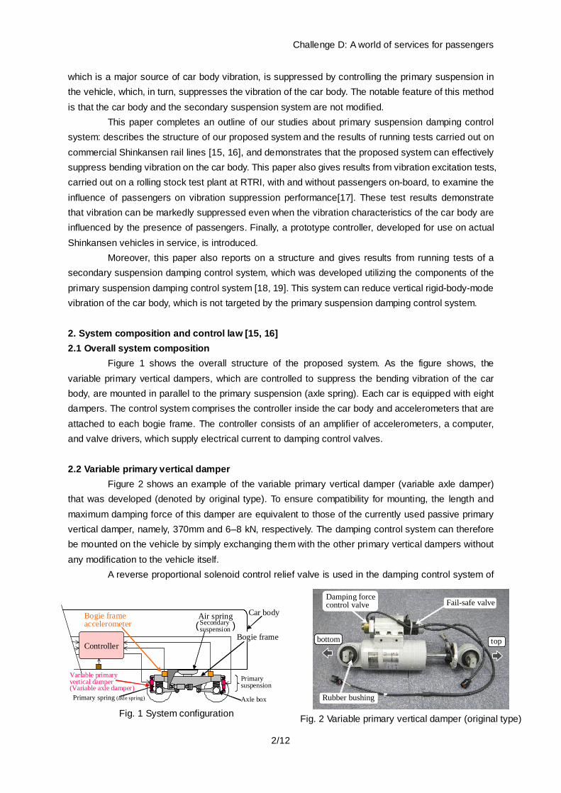
Figure 1 shows the overall structure of the proposed system. As the figure shows, the variable primary vertical dampers, which are controlled to suppress the bending vibration of the car body, are mounted in parallel to the primary suspension (axle spring). Each car is equipped with eight dampers. The control system comprises the controller inside the car body and accelerometers that are attached to each bogie frame. The controller consists of an amplifier of accelerometers, a computer, and valve drivers, which supply electrical current to damping control valves. 2.2 Variable primary vertical damper
Figure 2 shows an example of the variable primary vertical damper (variable axle damper) that was developed (denoted by original type). To ensure compatibility for mounting, the length and maximum damping force of this damper are equivalent to those of the currently used passive primary vertical damper, namely, 370mm and 6–8 kN, respectively. The damping control system can therefore be mounted on the vehicle by simply exchanging them with the other primary vertical dampers without any modification to the vehicle itself.
A reverse proportional solenoid control relief valve is used in the damping control system of
Variable primaryvertical damper(Variable axle damper)
Air spring Car body
ControllerBogie frame
Bogie frame accelerometer
Primary spring (axle spring)
Primarysuspension
Secondarysuspension( )
Axle box Fig. 1 System configuration
bottom top
Fail-safe valveDamping forcecontrol valve
Rubber bushing
Fig. 2 Variable primary vertical damper (original type)

Challenge D: A world of services for passengers
3/12
the variable primary vertical damper [20]. Figure 3(a) shows the command current vs. damping force characteristics of the variable primary vertical damper in the extension and compression directions at a fixed piston speed. In general, the Karnopp approximation referred to in [21], which is an approximation method for command values, is widely used in semi-active control. Depending on the direction of the piston stroke velocity, the variable primary vertical damper may generate force only in the direction opposite to that required. In this case, it should be commanded to suppress the damping force to the maximum extent possible. A control valve with a built-in Karnopp approximation law function is incorporated into the variable primary vertical damper. This damper generates a damping force during its extension (denoted as ‘Extension’ in the figure) at a small command current (approximately 0.3 A), which falls to a minimum during its compression (denoted as ‘Compression’ in the figure).When the command current is increased to approximately 1.3 A, the opposite behavior is observed. At an intermediate command current (approximately 0.9 A), only a small damping force is generated during extension or compression. Thus, the direction of the damping force generated by the variable primary vertical damper can be controlled by the command current alone, eliminating the need to consider the piston stroke velocity of the damper from the point of view of the controller. It is therefore possible to control the damper without measuring its displacement. In this case command currents of less than 0.3 A or more than 1.3 A are not used.
Figure 3(b) shows the piston speed vs. damping force characteristics of the variable primary vertical damper at a fixed command current. The damping force varies in the region between the lines denoting minimum (0.9 A) and maximum damping (0.3 A). The damping force of the variable primary vertical damper has a range of approximately 5 kN, excluding the region of very low piston speed, and almost covers the complete damping force range of the conventional passive primary vertical damper (denoted as ‘Passive damper’ in the figure)
In high-speed running on commercial Shinkansen lines, the control system is required to have a fail-safe feature. To achieve this, a switching valve interlocked with the system power was installed (the fail-safe valve in Fig. 2) such that the damping force characteristic of the primary vertical damper when the system power is turned off (denoted as ‘Power off ’ in Fig. 3(b)) is as close as possible to that of the currently used passive primary vertical damper. Even when an error occurs in the control system, it is therefore possible to run a vehicle under almost normal conditions by turning off the system power.
In subsequent improvements to this system, aimed at reducing the manufacturing cost and
-6
-4
-2
0
2
4
6
0.3 0.5 0.7 0.9 1.1 1.3
Electric current [A]
Dam
ping
forc
e [k
N]
Extension(0.03m/s)Extension(0.05m/s)Compression(0.03m/s)Compression(0.05m/s)
0
1
2
3
4
5
6
0 0.05 0.1 0.15 0.2Piston speed [m/s]
Dam
ping
forc
e [k
N]
Power offMax. damping(0.3A)Min. damping(0.9A)Passive damper
(a) Between command current and damping force (b) Between piston speed and damping force
Fig.3 Characteristics of variable primary vertical damper
Challenge D: A world of services for passengers
4/12
improving reliability, we succeeded in integrating control and switching valve functions; therefore, a similar fail-safe function was realized by employing one control valve per damper in the running tests described below (denoted by ‘improved type’), on the Tohoku Shinkansen line (Case B) and in the subsequent tests [16]. 2.3 Control algorithm
Various control laws can be applied for controlling variable primary vertical dampers. In this study, we adopted two control laws, depending on the characteristics of the vehicle to be tested, introduced below:
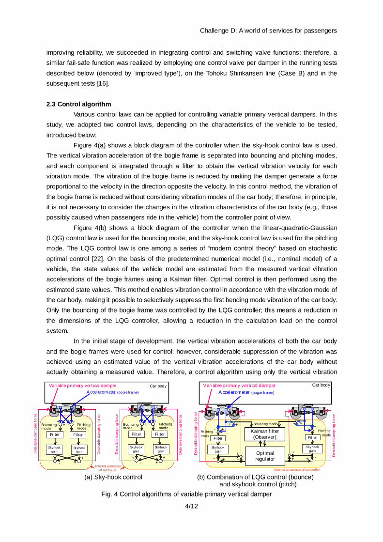
Figure 4(a) shows a block diagram of the controller when the sky-hook control law is used. The vertical vibration acceleration of the bogie frame is separated into bouncing and pitching modes, and each component is integrated through a filter to obtain the vertical vibration velocity for each vibration mode. The vibration of the bogie frame is reduced by making the damper generate a force proportional to the velocity in the direction opposite the velocity. In this control method, the vibration of the bogie frame is reduced without considering vibration modes of the car body; therefore, in principle, it is not necessary to consider the changes in the vibration characteristics of the car body (e.g., those possibly caused when passengers ride in the vehicle) from the controller point of view.
Figure 4(b) shows a block diagram of the controller when the linear-quadratic-Gaussian (LQG) control law is used for the bouncing mode, and the sky-hook control law is used for the pitching mode. The LQG control law is one among a series of “modern control theory” based on stochastic optimal control [22]. On the basis of the predetermined numerical model (i.e., nominal model) of a vehicle, the state values of the vehicle model are estimated from the measured vertical vibration accelerations of the bogie frames using a Kalman filter. Optimal control is then performed using the estimated state values. This method enables vibration control in accordance with the vibration mode of the car body, making it possible to selectively suppress the first bending mode vibration of the car body. Only the bouncing of the bogie frame was controlled by the LQG controller; this means a reduction in the dimensions of the LQG controller, allowing a reduction in the calculation load on the control system.
In the initial stage of development, the vertical vibration accelerations of both the car body and the bogie frames were used for control; however, considerable suppression of the vibration was achieved using an estimated value of the vertical vibration accelerations of the car body without actually obtaining a measured value. Therefore, a control algorithm using only the vertical vibration
++ - +
++
+-
Variable primary vertical damper Car bodyAccelerometer (bogie frame)
++ - +
Filter
Skyhookgain
++
+-
Bouncingmode
Pitchingmode
SkyhookgainD
esir
able
dam
pin
g fo
rce
Internal processesof controller
Filter
Des
irab
le d
ampi
ng fo
rce
Filter
Skyhookgain
Bouncingmode
Pitchingmode
Skyhookgain
Filter
Des
irab
le d
ampi
ng fo
rce
Des
irab
le d
ampi
ng fo
rce
Kalman filter(Observer)
Optimalregulator
Bouncing mode
Pitchingmode
Pitchingmode
+-
Filter
- + +
+
Skyhookgain
+ + +-
Filter
-++
+
Skyhookgain
++
Variable primary vertical damper Car body
Accelerometer (bogie frame)
Des
irab
le d
ampi
ng fo
rce
Des
irab
le d
ampi
ng fo
rce
Internal processes of controller (a) Sky-hook control (b) Combination of LQG control (bounce)
and skyhook control (pitch) Fig. 4 Control algorithms of variable primary vertical damper

Challenge D: A world of services for passengers
5/12
accelerations of the bogie frames is currently used, as shown in Fig. 4(b).
3. Demonstration in running tests using an actual vehicle As the favorable effects of proposed system on the suppression of vibration had been
confirmed by numerical simulation and vibration tests using a rolling stock test plant [23], the vehicle running tests were carried out on the Sanyo and Tohoku Shinkansen lines with the cooperation of the West Japan Railway Company and the East Japan Railway Company. In the running tests, each vehicle ran several times along a test section at a constant speed to measure vibration under different conditions of the primary vertical damper, the control law, and the control parameters. The test section includes various track conditions, i.e., curved and straight tracks, tunnels, bridges, stations, and ballasted and slab tracks.
In the test results shown below, Case A refers to the case of using the sky-hook control law, and Case B refers to the case of using the LQG control law. The validity of these control laws depends on the characteristics of the vehicle for which this system is intended. In our subsequent study [15], sky-hook control was also effective in improving the ride comfort particularly when the natural frequency of the first bending mode vibration of the car body was close to that of the bogie; LQG control was also effective in improving the ride comfort, particularly when the two natural frequencies were further apart from each other. For effective car body vibration suppression and ride comfort improvement, it is important to select the appropriate control law and adapt the parameters to the specifications of the vehicle. 3.1. Running test (case A) [15]
This was the first attempt to carry out high-speed vehicle running tests on commercial lines while controlling the primary suspension system in order to suppress the vertical vibration of the railway vehicle. The Shinkansen vehicle used in the test had a body length of 24.5 m and with a car-body mass of 27,000 kg. Figure 5 shows the condition under which the variable primary vertical damper (original type) was mounted on the test vehicle. Figures 6(a) and 6(b)
Variable primaryvertical damper Axle box
Bogieframe
Fig. 5 Installation of variable primary vertical damper (original type)
0.5 1 2 3 4 5 8 10 2010-3
10-2
10-1
100
Frequency [Hz]
Acc
eler
atio
n PS
D [(
m/s2 )2 /H
z]
PassiveSky-hook
0.5 1 2 3 4 5 8 10 2010-4
10-3
10-2
Frequency [Hz]
Acc
eler
atio
n PS
D [(
m/s2 )2 /H
z]
PassiveSky-hook
(a) Acceleration PSD of rear bogie frame (b) Acceleration PSD at floor of car body center
Fig. 6 Vehicle running test results (case A: using sky-hook control algorithm at Sanyo Shinkansen)
Challenge D: A world of services for passengers
6/12
show the acceleration power spectral density (PSD) of the vertical vibration of the vehicle for a section of approximately 5 km (approximately 60 s), during which there is marked car body vibration. The vehicle was running at a constant speed of 300 km/h along the section.
Under sky-hook control (‘Sky-hook’ in the figures), the vibration acceleration of the bogie frame (Fig. 6(a)) was reduced throughout when around the frequency band of approximately 4-12 Hz, in comparison to when currently used passive primary vertical damper are employed (in the figures marked ‘Passive’). As a result, the acceleration PSD at the floor of the car body center (Fig. 6(b)) was also reduced when in the vicinity of the frequency band of 4-12 Hz, and in particular, the acceleration PSD peak at 8.6 Hz was reduced by approximately 80%. No increase in vibration due to the controlling dampers was observed in any frequency band, confirming the effective suppression of car body vibration. 3.2. Running test (case B) [16]
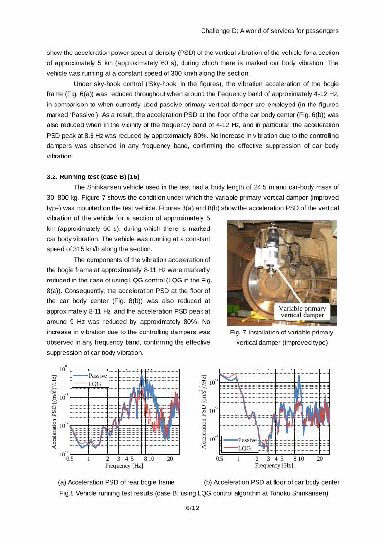
The Shinkansen vehicle used in the test had a body length of 24.5 m and car-body mass of 30, 800 kg. Figure 7 shows the condition under which the variable primary vertical damper (improved type) was mounted on the test vehicle. Figures 8(a) and 8(b) show the acceleration PSD of the vertical vibration of the vehicle for a section of approximately 5 km (approximately 60 s), during which there is marked car body vibration. The vehicle was running at a constant speed of 315 km/h along the section.
The components of the vibration acceleration of the bogie frame at approximately 8-11 Hz were markedly reduced in the case of using LQG control (LQG in the Fig. 8(a)). Consequently, the acceleration PSD at the floor of the car body center (Fig. 8(b)) was also reduced at approximately 8-11 Hz, and the acceleration PSD peak at around 9 Hz was reduced by approximately 80%. No increase in vibration due to the controlling dampers was observed in any frequency band, confirming the effective suppression of car body vibration.
0.5 1 2 3 4 5 8 10 2010
-3
10-2
10-1
100
Frequency [Hz]
Acc
eler
atio
n PS
D [(
m/s2 )2 /H
z]
PassiveLQG
0.5 1 2 3 4 5 8 10 20
10-4
10-3
10-2
Frequency [Hz]
Acc
eler
atio
n PS
D [(
m/s2 )2 /H
z]
PassiveLQG
(a) Acceleration PSD of rear bogie frame (b) Acceleration PSD at floor of car body center
Fig.8 Vehicle running test results (case B: using LQG control algorithm at Tohoku Shinkansen)
Variable primaryvertical damper
Fig. 7 Installation of variable primary
vertical damper (improved type)

Challenge D: A world of services for passengers
7/12
4. Examination of the influence of passengers on vibration suppression [17] All the above running tests were carried out without passengers. In general, however, the
elastic-vibration characteristics of a car body change in the presence of passengers and also differ from those of the car body with a load (e.g., iron blocks) [24, 25]. This change in the vibration characteristics of the car body may affect the vibration suppression performance of this system. Therefore, vehicle excitation tests were carried out on the rolling stock test plant at RTRI with passengers to simulate running on actual tracks, and vibration characteristics of the car body and the vibration suppression performance of the system were therefore evaluated with and without on-board passengers. 4.1 Conditions of the vibration excitation test
Figure 9 shows a photograph of the test vehicle which has a ‘double-skin’ (extended hollow aluminum alloy) structure and is made of aluminum alloy similar to Shinkansen vehicles (Fig. 9(a)). It has a length of 24.5 m and a weight of approximately 31,000 kg (without passengers). We used Shinkansen bogies and replaced the primary vertical dampers with the variable primary vertical dampers (Fig. 9(b)). Figure 9(c) shows the interior of the vehicle with passengers. The legs and backs of the seats in the test vehicle were made of iron, unlike those in usual vehicles in service, and there were no cushions on the seats. The passengers kept their feet on the floor and their backs against the seat backs.
The excitation test was carried out for three cases in terms of vehicle load: the test car without passengers, the car with passengers, and the car with iron blocks (acting as deadweights) . Figure 10 shows the arrangement of on-board passengers and their weights (self-reported figures). In the case when passengers were replaced with deadweights, the deadweights were placed where each passenger sat (on the surface of the seat) and their total weight approximately corresponded to the total weight of
(a) Cover shot of test vehicle
(b) Installation of variable primary vertical damper
(c) Interior of the test car with passenger seated
Fig.9 Excitation test at rolling stock test plant
56
72
700
980 970 980 980 975 980 980 9803450 980975980 980980 990 990 990966.51960
1200
86 65 80
667264716260
67
59757056.55169.56772.544.563
7058655780.556.2
50.548.6
69
68.5 83.7 57.267 75 6567 69.5 68.556 68 65 7867 75 6567 69.5 68.556 68 65 78
24500
230
190
830
7070Body mass of a passenger [kg]
[mm]
Fig.10 Weighting condition on excitation test at RTRI (43 passengers, total: 2823kg)

Challenge D: A world of services for passengers
8/12
the passengers. Because the weight of each deadweight was approximately 15 kg, there was some difference between the weights of passengers and those of the corresponding deadweights.
The vibration excitation signals in the vertical and rolling directions were calculated from the vertical vibration acceleration of axle boxes obtained in running tests using Shinkansen vehicles. The vibration of the vehicle running on an actual track was simulated by applying these signals to the roller rigs of the test plant, on which the vehicle was placed, with a time delay between each wheelset corresponding to a running speed of 315 km/h. The amplitude, however, was set to 90% of that in actual running because of restrictions on the test plant. 4.2 Results of the vibration excitation test
Although excitation test using both the sky-hook and LQG control laws were carried out, only the results of the latter are given here. The reason for this is as follows: for the LQG control law, a controller was designed using a nominal vehicle model without passengers. Therefore, we were concerned that increases in the car body damping and slight changes in the natural frequency owing to the additional dynamic characteristics of passengers, which are not considered in the nominal model, may adversely affect the vibration suppression performance of this system in the presence of passengers.
Figure 11(a) shows the results of the excitation tests on the car both without passengers and with 43 passengers. An acceleration PSD peak due to the first bending mode vibration of the car body was observed at approximately 9 Hz at the car body center without passengers (blue line in Fig. 11(a)). Focusing on the cases without control, this acceleration PSD peak decreased in the presence of passengers; however, the change in frequency at the acceleration PSD peak was very small (green line in Fig. 11(a)). With control, the acceleration PSD peak at approximately 9 Hz decreased compared to cases without control, regardless of whether passengers were on-board or not, and the acceleration PSD in other frequency bands did not increase. Moreover, the acceleration PSD peak with control and 43 passengers was lower than that in the case with control without passengers. Thus, even when passengers were on-board, vibrations were suppressed using the same control parameters as those used in the case without passengers. This result was also confirmed by numerical simulation using 7-DOF vehicle model combined with passenger models in our subsequent study [26].
For reference, the excitation test results for the car loaded with deadweights corresponding to the total weight of 43 passengers is shown in Fig. 11(b). In the cases without control, the frequency at
0.5 1 2 3 4 5 8 10 2010-5
10-4
10-3
10-2
Frequency [Hz]
Acc
eler
atio
n PS
D [(
m/s2 )2 /H
z]
Passive(w/o passenger)Passive(w passenger)Control(w/o passenger)Control(w passenger)
Passive(w/o passenger)Passive(w passenger)Control(w/o passenger)Control(w passenger)
0.5 1 2 3 4 5 8 10 2010-5
10-4
10-3
10-2
Frequency [Hz]
Acc
eler
atio
n PS
D [(
m/s2 )2 /H
z]
Passive(w/o weight)Passive(w weight)Control(w/o weight)Control(w weight)
Passive(w/o weight)Passive(w weight)Control(w/o weight)Control(w weight)
(a) with / without passengers (b) with / without deadweights
Fig.11 Vertical acceleration PSD at car body center (Excitation test results at rolling stock test plant)

Challenge D: A world of services for passengers
9/12
the acceleration PSD peak due to the first bending mode vibration of the car body was lower when the car was loaded with deadweights, in contrast to the case with passengers. Comparing the cases under the same loading weight, the acceleration PSD peak at approximately 9 Hz decreased and no increase in the acceleration PSD at other frequencies was observed when the damping forces of primary vertical dampers were controlled.
When deadweights were used, however, the acceleration PSD peaks at approximately 8-9 Hz, i.e., near the main target frequency of control (9 Hz), increased slightly when vibration was controlled. This was considered to be due to the natural frequency of the first bending mode of the car body changing because of the deadweight load, causing a modeling error; thus, the expected effect of LQG control was not fully obtained. In contrast, no deterioration in the performance of vibration suppression was observed when passengers were on-board, probably due to the fact there was little change in the natural frequency of the first bending mode of the car body as a result of the passengers on-board.
The trends in the change of the vibration characteristics of the car body without control in this study were roughly in agreement with those obtained in the previous test [25]. The reason for this, as explained in Ref. 27, is considered to be that on-board passengers produce the same effect as a dynamic damper owing to their mass as well as their spring and damping characteristics, in contrast to the deadweights which merely added weight to the car body. 5. Other developments 5.1 Medium-range durability vehicle running tests and damper improvements
After the running tests described in Section 3.2, medium-range vehicle running test over approximately 76,000 km were carried out to determine the durability of the dampers. No fatal damage to the dampers was observed and their basic structure was confirmed to be satisfactory. On the basis of these test results, a mechanism was added to remove the air from the operating oil in the dampers and some of the components were reexamined to improve some practical features and the reliability of the dampers. 5.2 Development of a prototype controller for use on actual vehicles
A prototype controller was built in order to apply this system in practice. Figure 12 shows its appearance. The dimensions of the controller are 200 mm (W) × 280 mm (D) × 260 mm (H), and its weight is 5.5 kg. This controller has an amplifier for the accelerometers, a computer for calculating control command values, and drivers for the control valves installed on the variable primary vertical dampers. There is also a fault detection function in both the acceleration sensors and the controller itself. A new fault detection algorithm was developed for the primary vertical dampers by using the acceleration of the bogie frames and the vehicle running speed [28]. The aim now is to incorporate it into this controller. In case of a detected fault, the controller turns the characteristic of the dampers into ‘passive’ by shutting off the electrical current to the dampers, so that the vehicle can run as usual. Information about the faults is displayed on a 7 segment LED
Fig.12 Overview of prototype of controller

Challenge D: A world of services for passengers
10/12
attached to the controller and is recorded in a flash memory in the controller. This information can be downloaded by connecting a PC for maintenance. 5.3 Application for a secondary suspension damping control system [18, 19]
Unlike Shinkansen lines, some conventional railway tracks are subject to lower maintenance criteria. This usually implies large vertical irregularities and/or depressions at the rail joints, which are a known cause of vertical rigid-body-mode vibration of the car body. Since suppressing such vibration is necessary for improving ride comfort, a secondary suspension damping force control system with variable vertical dampers (a vibration control system) is also being developed at RTRI by utilizing primary suspension damping control system technology.
Figure 13 shows the overall structure of the proposed secondary suspension damping control system. As the figure shows, variable secondary vertical dampers, which are controlled to suppress car body vibrations, are mounted parallel to the secondary suspension. Four dampers are used per car. The controller calculates the damping force needed for the dampers to suppress vertical car body vibration acceleration with data obtained from acceleration sensors, and supplies a command current to the dampers. Two to four acceleration sensors are generally used; the number and position of acceleration sensors to be mounted on the car body will depend on the number and shape of vibration modes of the car body to be controlled. The control algorithm which controls variable dampers is based on the sky-hook control theory.
Vehicle running tests were carried out with the cooperation of Kyushu Japan Railway Company [19]. The test vehicle, which was a typical meter-gauge DMU (diesel multiple unit) for regional operation, has a car length of 20.8 m and a distance between bogie centers of 14 m. Figure 14 shows how the variable vertical damper was mounted on the test vehicle.
Figure 15 shows the PSD of vertical vibration acceleration along a section of the local line used in the tests (section with a running speed of 83 km/h) where rigid-body-mode vibration of the car body was particularly marked. An acceleration PSD peak due to rigid-body-mode vibration was observed at approximately 1.9 Hz, directly above the rear bogie center. In the case of controlled dampers, vibrations with a frequency of 2 Hz or lower was generally suppressed compared with the case without
Variable secondaryvertical damper
Secondarysuspension
Fig.14 Installation of variable secondary
vertical damper to DMU
Variable secondaryvertical damper
Controller
Accelerometer
Fig.13 Composition of secondary suspension
damping control system
0.5 1 2 3 4 5 8 10 2010- 4
10- 3
10- 2
10- 1
100
周波数 [Hz]
加速
度PS
D [(
m/s
2 )2 /Hz]
Frequency [Hz]
Acc
eler
atio
n PS
D [(
m/s2 )
2 /H
z] without controlwith control
Fig 15 Acceleration PSD at floor above rear bogie center (Vehicle running test, running speed: 83km/h)

Challenge D: A world of services for passengers
11/12
control, and the PSD peak at 1.9 Hz was markedly reduced by approximately 75%. 6. Conclusions
This study was the first attempt to carry out high-speed vehicle running tests on commercial lines while controlling the primary suspension system in order to suppress the vertical vibration of the railway vehicle. This allowed successful demonstration of the significant effects of the proposed system on the suppression of car body vibration and the improvement of ride comfort. In addition, we demonstrated by performing excitation tests that the control system can effectively suppress the vibration of a car body with or without passengers, using the same control parameters.
The proposed system suppresses the first bending mode vibration of the car body through the use of a relatively simple structure and control law. Moreover, the proposed system can be mounted on currently-used vehicles with little modification of the vehicles because it simply requires changing the damper and mounting the accelerometers and controllers; as such, the system is highly practical. As explained in Section 5, the control system is being improved as necessary by developing various prototypes and performing various demonstrative tests aimed at practical application of the control system.
Thus, the development of this system has moved from demonstration of a principle to the stage of practical application. Moreover, a system to suppress rigid-body-mode vertical vibration is also being developed by utilizing the primary suspension damping control system technology. This new system will soon be incorporated into actual vehicles in service. Acknowledgment
We would like to express our deepest gratitude to the relevant personnel at the Hitachi Automotive Systems, Ltd for their contribution and the development of the variable primary and secondary vertical dampers; and also to the relevant personnel at the West Japan Railway Company, the East Japan Railway Company and the Kyushu Railway Company, who provided valuable opportunities for performing the vehicle running tests.
References [1] Oishi, T., et al., “Development of Advanced semi-active suspension system for Shinkansen vehicle”, In Proceedings of the International Symposium on Speed-up Safety and Service Technology for Railway and Maglev Systems 2003(STECH’03), Tokyo, Japan, Aug.19-22, 2003, pp. 220-224. [2] Tahara, M., et al., “Practical use of an active suspension system for railway vehicle,” In Proceedings of the International Symposium on Speed-up Safety and Service Technology for Railway and Maglev Systems 2003(STECH’03), Tokyo, Japan, Aug.19-22, 2003, pp.225-228. [3] Suzuki, Y. et al., “Theoretical analysis of flexural vibration of car body,” Quarterly Report of RTRI, Vol. 31, No.1, 1990, pp.42-48. [4] Suzuki, H., “Research trends on riding comfort evaluation in Japan,” Proceedings of the Institution of Mechanical Engineers, Part F: Journal of Rail and Rapid Transit, Vol. 212, No.1, 1998, pp.61-72. [5] Morimura, T. et al., “The course of achieving 270 km/h operation for Tokaido Shinkansen. Part 1: technology and operations overview,” Proceedings of the Institution of Mechanical Engineers, Part F: Journal of Rail and Rapid Transit, Vol. 219, No.1, 2005, pp.21-26. [6] Suzuki, Y. et al., “Methods for flexural vibration damping for rolling stock carbody,” Quarterly Report of RTRI, Vol. 38, No.3, 1997, pp.123-128. [7] Ishikawa, R. et al., “Decrease of Vehicle Body Bending Vibration by Dynamic Damper,” In Proceedings of the 68th Annual Meeting of the Japan Society of Mechanical Engineers, Tokyo, Japan, Mar. 4, 1991, Vol. C, 1991,

Challenge D: A world of services for passengers
12/12
pp.531-533 (in Japanese). [8] Tomioka, T. et al., “Reduction of bending vibration in railway vehicle carbodies using carbody-bogie dynamic interaction,” Vehicle System Dynamics, Vol. 48, Supplement, 2010, pp.467-486. [9] Takigami, T. et al., “Bending Vibration Suppression of Railway Vehicle Carbody with Piezoelectric Elements (Experimental Results of Excitation Tests with a Commuter Car),” Journal of Mechanical Systems for Transportation and Logistics, Vol.1, No.1, 2008, pp.111-121. [10] G., Schandl et al., “Comfort enhancement by an active vibration reduction system for a flexible railway car body,” Vehicle System Dynamics, Vol.45, No.9, 2007, pp.835-847. [11] Kambayashi, K.et al., “Development of an active vibration control systems for high speed railway vehicles,” In Proceedings of the 5th Jointed Railway Technology Symposium (J-Rail’98), Tokyo, Japan, Nov. 25-27, 1998, pp. 499–502 (in Japanese). [12] Hac, A., “Stochastic Optimal Control of Vehicles with Elastic Body and Active Suspension,” Transactions of the ASME, Journal of Dynamic Systems and Control, Vol.108, No.2, 1986, pp.106-110. [13] Foo, E., and Goodall, R. M., “Active suspension control of flexible-bodied railway vehicles using electro-hydraulic and electro-magnetic actuators,” Control Engineering Practice, Vol. 8, No.5, 2000, pp.507-518. [14] Sugahara, Y. et al., “Suppressing vertical vibration in railway vehicles through primary suspension damping force control,” Journal of System Design and Dynamics, Vol.1, No.2, 2007, pp. 224-235. [15] Sugahara, Y. et al., “Suppression of Vertical Bending Vibration in Railway Car Bodies by Primary Suspension Damping Control (Results of Running Tests Using Shinkansen Vehicles),” In Proceedings of the 21th International Symposium on Dynamics of Vehicles on Roads and Tracks (IAVSD’09), Stockholm, Sweden, Aug. 17-21, 2009, Paper No. 13. [16] Sugahara, Y. et al., “Suppression of vertical bending vibration of railway vehicle car bodies by primary suspension damping control,” In Proceedings of the Spring Conference of Japan Fluid Power System Society 2009, Miyagi, Japan, Jun. 25-26, 2009, pp.59-61 (in Japanese). [17] Sugahara, Y. et al., “Influence of Passengers on the Vibration Suppression Performance of Primary Damping Control System of Railway Vehicles,” RTRI Report, Vol.25, No.1, 2011, pp.11-16. [18] Sugahara, Y. et al., “Vertical Vibration Suppression of Railway Vehicle by Damping Control of Secondary Vertical Damper,” In Proceedings of the 8th International Conference on Railway Bogie and Running Gear (BOGIE ’10), Budapest, Hungary, Sep. 13-16, 2010. pp. 94-96. [19] Sugahara, Y. et al., “Suppression of Vertical Vibration of Railway Vehicles by Damping Control of Secondary Vertical Oil Damper,” In Proceedings of the 5th Jointed Railway Technology Symposium (J-Rail 2010), Tokyo, Japan, Dec. 15-17, 2010, pp. 179–182 (in Japanese). [20] Kimura, T., “Development of Semi-Active Suspension System,” Journal of Society of Automotive Engineers of Japan, Vol. 58, No.4, 2004, pp.76-80 (in Japanese). [21] Karnopp, D. et al., “Vibration Control Using Semi-Active Force Generators,” Transactions of the American Society of Mechanical Engineers, Journal of Engineering for Industry, Vol.96, No.2, 1974, pp.619-626. [22] B.D.O. Anderson et al., “Linear Optimal Control”, Prentice-Hall, 1971. [23] Sugahara, Y. et al., “Suppression of Vertical Vibration in Railway Vehicles by Damping Force Control of Primary Suspension Using an LQG Controller,” Journal of System Design and Dynamics, Vol.2, No.1, 2008, pp.251-262. [24] Kaneda, T. et al., “Study of human body effect to vibration of railway vehicle body,” In Proceedings of the 75th JSME Kansai District Conference, Shiga, Japan, Mar. 16-17, 2000, No.004-1, pp.29-30, (in Japanese). [25] Tomioka, T. et al. , “Vibration Damping due to Passengers on Flexural Vibration of Railway Vehicle Carbodies during Running,” In Proceedings of the Dynamics and Design Conference 2010(D&D2010), Nara, Japan, Sep. 14-18, 2010, presentation No. 542 (CD-ROM) (in Japanese). [26] Koganei, R. et al., “Model of railway vehicle and the efficacy of vibration suppression by the proposed control system including passengers”, In Proceedings of the 19th Transportation and Logistics Conference 2010, Kanagawa, Japan, Dec. 1-3, 2010, No.10-54, pp.45-48 (in Japanese). [27] Nagai, M. et al., “Coupled vibration of passenger and lightweight car-body in consideration of human-body biomechanics,” Vehicle System Dynamics, Vol.44, Supplement, pp.601-611, 2006. [28] Kojima, T. et al., “Fault detection of primary vertical dampers of railway vehicles using phase difference between vibration modes,” In Proceedings of the 19th Transportation and Logistics Conference 2010, Kanagawa, Japan, Dec. 1-3, 2010, No.10-54, pp.41-44 (in Japanese).