Design of a Highly Portable Data Logging Embedded System ...

Development of Portable Embedded Face Recognition
Prototype
By
Prasad S Garapati
A thesis submitted to the School of Computing of
Florida Institute of Technology
In fulfillment of the requirements
For the degree of
Master of Science
In
Computer Science
Melbourne, Florida
December 2018

We the undersigned committee hereby approve the attached thesis,
“Development of Portable Embedded Face Recognition Prototype,” by
Prasad S. Garapati.
_____________________________________________
Dr. Michael King, Major Advisor
Associate Professor
Department of Computer Engineering and Science
_____________________________________________
Dr. Marius Silaghi, Committee Member
Associate Professor
Department of Computer Engineering and Science
_____________________________________________
Dr. Munnevver Subasi, Committee Member
Associate Professor
Department of Mathematical Science
_____________________________________________
Dr. Philip J. Bernhard
Associate Professor and Department Head
Department of Computer Engineering and Science

iii
Abstract
Title: Development of Portable Embedded Face Recognition Prototype
Author: Prasad S Garapati
Advisor: Dr. Michael King, Ph.D.
In this thesis, we focus on developing a prototype for collecting multispectral
images for face recognition. With such application, the quality of the image is an
important factor that affects the accuracy of the recognition. However, the sensory
data either provided in RGB channel or in NIR channel. The images acquired in
RGB and NIR were never aligned in previous developments during my literature
study. Thus, I propose an embedded system prototype capable of acquiring NIR
and RGB images providing multispectral information which is computation
efficient for real time face recognition applications.
Keywords: multispectral image, face recognition, embedded prototype, x86 Linux-
BSP.

iv
3.
Table of Contents
Abstract ................................................................................................................................. iii
Acknowledgements .............................................................................................................. vi
List of Figures ....................................................................................................................... vii
Abbreviations ...................................................................................................................... viii
1.0 INTRODUCTION .......................................................................................................... 1
2.0 Background ................................................................................................................ 4
2.1 NIR Quantum Efficiency ......................................................................................... 7
2.2 Optimal Wavelength in Bio-Medical Application .................................................. 8
2.3 Optimal Wavelength in Face Recognition ............................................................. 9
3.0 LITERATURE STUDY .................................................................................................. 11
3.1 NIR-to-Visible Face Recognition .......................................................................... 11
3.2 NEAR-IR Approaches ............................................................................................ 13
3.3 Camera and Filters ............................................................................................... 14
3.4 Near-IR as Spatial Information............................................................................. 14
3.5 Image Registration ............................................................................................... 14
3.6 PCA and other Luminance-chrominance methods .............................................. 15
3.7 Wasserstein CNN: Learning Invariant Features for NIR-VIS Face Recognition .... 22
3.8 CASIA NIR-VIS 2.0 Face Database ........................................................................ 25
3.9 Overview of Spectral Imaging of Human Skin toward Face Recognition ............ 26
3.10 Multispectral Biometric Data for Cross-Spectral Identification Applications ...... 29
3.11 Hyperspectral Face Databases for Facial Recognition Research ......................... 33
4.0 EXPERIMENTAL DESIGN ........................................................................................... 37
4.1 Hardware ............................................................................................................. 37
4.1.1 JAI-AD-080GE Camera.......................................................................................... 38
4.2 Hardware BSP Linux X86 ...................................................................................... 38
4.3 OpenCV Installation ............................................................................................. 39
4.4 MySQL Client Development ................................................................................. 40
4.5 MySQL Server Configuration ............................................................................... 40

v
3.
4.6 Pleora eBUS SDK .................................................................................................. 40
4.6.1 Target System Requirement ................................................................................ 40
4.6.2 Tool Requirements .............................................................................................. 41
4.6.3 Installing the eBUS SDK for Linux ......................................................................... 41
4.6.4 Install and run eBUSd .......................................................................................... 42
4.6.5 Compiling and Running Sample Applications ...................................................... 43
4.6.6 Pleora Software Development............................................................................. 43
4.7 Enrollment Process .............................................................................................. 45
4.8 Pleora Camera Interface ...................................................................................... 45
4.9 Aravis Software Installation ................................................................................. 47
4.10 Block Diagram ...................................................................................................... 48
5.0 ENROLLMENT SOFTWARE DESIGN .......................................................................... 49
6.0 EXPERIMENTAL RESULTS ......................................................................................... 52
6.1 Alignment............................................................................................................. 52
6.2 Selected Parameters ............................................................................................ 52
6.3 Experiments and Results ..................................................................................... 54
7.0 CONCLUSION ........................................................................................................... 60
8.0 FUTURE WORK ......................................................................................................... 61
9.0 References ............................................................................................................... 63
10.0 Appendix .................................................................................................................. 65
10.1 A Kontron Embedded Board Interfaces ............................................................... 65
10.2 B Network Infrastructure CentOS server installation .......................................... 72
10.3 C KDE Plasma Workspace Installation ................................................................. 74
10.4 D OpenCV Target Installation .............................................................................. 74
10.5 E Source mysqlmsfrDBClient.cpp ......................................................................... 80
10.6 F MySQL Server Configuration ............................................................................. 83
10.7 G DHCP Server Installation .................................................................................. 94
10.8 H Installing the eBUS SDK for the x86 or x64 for Linux platform......................... 96
10.9 I Installation of Aravis on CentOS Embedded Target .......................................... 97

vi
3.
Acknowledgements
First, I would like to thank my thesis advisor Dr. Michael King for his help,
support, guidance, patience, kindness and friendship. He is not just my advisor but
also my mentor who helped continuously in developing this project.
I would like also to thank my program advisor & my thesis committee member Dr.
Marius Silaghi for his important contributions, comments, ideas and invaluable
helpfulness during my entire master’s program at FIT. Dr. Silaghi’s remarks and
instructions have enormously contributed in enhancing my course work at Florida
Institute of Technology. I would like also thank Dr. Munevver Subasi for being a
member of my committee.
All my thanks also go to my colleagues at FIT Mr. Gio Benitez Torres, Mrs.
Krishna Priya and Mr. Kushal Vangara. Working closely with Bio-metric research
team for last seven months has been a wonderful experience.
My thesis acknowledgement would be incomplete without thanking my son, Bobby
Garapati, whose smiling face always made me happy and inspired me, though
missing my visits to Maryland during busy times of course work at FIT.
Special words for my sweetheart Vanisree for her love, kindness and patience, she
has been and always be my support. Thousands of words won’t be enough to
express my gratefulness for her.
I would like also to thank my parents for their unlimited support and care.

vii
3.
List of Figures
Figure 1 Face Recognition System ........................................................................................ 6
Figure 2 Quantum Efficiency ............................................................................................... 10
Figure 3 Com-Express Platform Board ................................................................................ 37
Figure 4 KDE Desktop .......................................................................................................... 39
Figure 5 Block Diagram ....................................................................................................... 48
Figure 6 Enrollment Architecture ....................................................................................... 50
Figure 7 Experimental Setup ............................................................................................... 54
Figure 8 Visible RGB Image ................................................................................................. 58
Figure 9 NIR Image .............................................................................................................. 59

viii
3.
Abbreviations
ATM Automated Teller Machine
CNN Convolutional Neural Networks
DNA Deoxyribonucleic Acid
GigE Gigabit Ethernet
HFR Heterogeneous Face Recognition
NIR Near Infra-red
PIN Personal Identification Number

1
1.0 INTRODUCTION
The information age is quickly revolutionizing the way transactions are completed.
Everyday actions are increasingly being handled electronically, instead of with
pencil and paper or face to face. This growth in electronic transactions has resulted
in a greater demand for fast and accurate user identification and authentication.
Access codes for buildings, banks accounts and computer systems often use PIN's
for identification and security clearances. Using the proper PIN gains access, but
the user of the PIN is not verified. When credit and ATM cards are lost or stolen,
an unauthorized user can often come up with the correct personal codes.
Despite warning, many people continue to choose easily guessed PIN‟s and
passwords: birthdays, phone numbers and social security numbers. Recent cases of
identity theft have heightened the need for methods to prove that someone is truly
who he/she claims to be.
Biometrics technology may solve this problem since a biometric is by definition
connected to its owner except in the case of identical twins. It’s nontransferable.
The system can then compare scans to records stored in a central or local database
or even on a smart card.
The input to the system is usually a color image and, in some cases, along with an
associated depth map taken by the camera subsystem. The system can be used in
two modes: authentication and recognition. The output of the system is either a
binary answer when the system is used for authentication of a priori known person,
or in the case of recognition, the code of the nearest person of a priori given face set
together with a reliability estimate.
Objectives of Thesis
Face recognition is involved in wide range of applications such as person
verification, authentication, and forensics etc. There are several face recognitions

2
systems are available in commercial and military applications. All these systems
can take images separately in visible and Near Infra-Red [NIR] region.
The objective of this design is to provide perfectly aligned registered images
simultaneously in visible and NIR regions. These perfectly registered images
reduce the computation and make the Face recognition algorithms efficient. The
design also provides a database in a MySQL database server. Another main
objective of this dissertation is to design the Hardware capable of communicating
over Wi-Fi and Cellular Network.
Contributions
The specific contributions of this thesis can be summarized as follows:
1. Design the state of the art embedded prototype capable of perfectly
aligned and registered images in visible and NIR region.
2. Design the software capable of detecting multiple GigE & GenICam
Cameras and provide the multi-spectral images for Face Recognition
Algorithms.
3. Design the Enrollment Module capable of registering the subjects in
local database client and remote Database Server.
4. Provide Hardware Platform for user interface and future extensions like
interfacing with Wi-Fi, Cellular Network Controller, Smart Data Card
and Low Voltage Digital Signal Communications.
Throughout this thesis, I focus on providing perfectly registered and aligned
images, reducing the computation time for Face Recognition algorithms. A
particular attention has been given to designing Enrollment and Database sub
modules in Face Recognition Embedded prototype to facilitate Face Recognition
Research on cross-spectral Face Recognition.

3
Overview of this Dissertation
This manuscript includes seven chapters: - Background, Literature study,
Experimental Design, Enrollment Software Design, Experimental Settings and
Results, Conclusion and Future Work.
In Chapter two, Background gives the information about Biometrics, available
technologies and components of Face Recognition.
In Chapter three, Literature Study gives the information about several researches
conducted using NIR Infrared spectral information for cross spectral and
multispectral Face Recognition.
In Chapter four, we present our Hardware design and Open Source software
installations. Also provides information about the special Camera JAI-AD-080 and
its interface details to Intel Atom processor.
In Chapter five, we present our Enrollment Software and Database designs. This
section also provides the user interface, registration capabilities of the enrollment
software along with accessing Database either from Client or from the Database
Server.
In Chapter six, we present the perfectly registered images from NIR and Visible
channels and system timing performance is identified.
In Chapter seven, we present the conclusion, referring to achieved results. In
chapter seven, future work is identified.

4
2.0 Background
The term “biometrics” is derived from the Greek words “bio” (life) and “metrics”
(to measure). Due to significant development in computer processing, automated
biometric systems become available over the last a few decades. Biometrics (or
biometric authentication) refers to the identification of humans by their
characteristics or traits. Biometrics is used in computer science as a form of
identification and access control. It is also used to identify individuals in groups
that are under surveillance. A biometric system is a recognition system, which
makes a personal identification by determining the authenticity of a specific
physiological or behavioral characteristic possessed by the user.
Depending on the context on which a biometric system works, it can be Either
classified as an identification system or a verification (authentication) system
identification involves in establishing a person’s identify whereas in verification
involves confirming or denying a person’s claiming identity.
Biometric security systems are using:
Physical human identifiers like fingerprint, face, iris, retina, DNA, hand
geometry and vein geometry.
Behavioral identifiers like speech, signature, and keystroke timing
Chemical identifiers like odor and body heat.
Biometric systems are used for two purposes. One is to verify that the user is
genuine by comparing the acquired biometric trait with the one stored for that user.
The other purpose the biometrics are used is to identify a user in which case the
acquired biometric trait is compared with a collection of the same traits from
multiple users.

5
Physiological biometrics (based on measurements and data derived from direct
measurement of a part of the human body) include:
a. Fingerprint Recognition
b. Facial Recognition
c. Iris Recognition
d. Retina-scan
e. Hand geometry
Behavioral biometrics (based on measurements and data derived from an action)
include:
a. Voice Recognition
b. Signature Recognition
c. Keystroke dynamics
A “biometric system” refers to the integrated hardware and software used to
conduct biometric identification or verification.
There are number of reasons to choose face recognition. This includes the
following:
Requires no physical interaction on behalf of the user.
It is accurate and allows for high enrolment and verification rates.
It does not require an expert to interpret the comparison result.
It is biometric that allows you to perform passive identification in a one to
many environments [e.g.: identifying a terrorist in a busy Airport terminal].

6
Components of Face Recognition System
Figure 1 Face Recognition System
A typical face recognition system consists of User Interface, Enrollment module,
Database and Verification Module.
User interface captures the analog or digital image of the person's face. In the
enrollment module the obtained sample is preprocessed and analyzed. This
analyzed data is stored in the database for the purpose of future comparison. The

7
database compresses the obtained sample and stores it. It should have retrieval
property also that is it compares all the stored sample with the newly obtained
sample and retrieves the matched sample for the purpose of verification by the user
and determine whether the match declared is right or wrong. The verification
module also consists of a preprocessing system. Verification means the system
checks as to who the person says he or she is and gives a yes or no decision. In this
module the newly obtained sample is preprocessed and compared with the sample
stored in the database. The decision is taken depending on the match obtained from
the database. Correspondingly the sample is accepted or rejected. Instead of
verification module we can make use of identification module. In this the sample is
compared with all the other samples stored in the database. For each comparison
made a match score is given. The decision to accept or reject the sample depends
on this match score falling above or below a predetermined threshold.
2.1 NIR Quantum Efficiency
The spectral sensitivity of the human eye lies between 380 nm – 700 nm. While the
visible range can be covered by CCD and CMOS cameras, the NIR range of 850
nm – 1400 nm is roughly covered by e-con Systems Cameras.
It has been customary to divide the IR spectrum into four sub-bands: near IR (NIR;
wavelength 0.75−1.4µm), short wave IR (SWIR; wavelength 1.4−3µm), and
medium wave IR (MWIR; wavelength 3 − 8µm), and long wave IR (LWIR;
wavelength 8 − 15µm). This division of the IR spectrum is also observed in the
manufacturing of IR cameras, which are often made with sensors that respond to
electromagnetic radiation constrained to a particular sub band.
Quantum efficiency (QE) is the measure of the effectiveness of an image to
produce electronic charge from incident photons.
There are two quantum efficiencies [external and internal quantum efficiency]
defined for a photo detector to measure how far it is responsive to the incident

8
photo stream at a specific wavelength. The external quantum efficiency is the
intended one since it measures the ratio of the collected photocurrent to the incident
photon flux at a specified wavelength. As this quantity increases the photo detector
is considered more responsive and thereby the device which has larger external
quantum efficiency at the specified wavelength will be more sensitive.
External Quantum Efficiency (EQE) is the ratio of the number of charge carriers
collected by the solar cell to the number of photons of a given energy shining on
the solar cell from outside (incident photons).
Internal Quantum Efficiency (IQE) is the ratio of the number of charge carriers
collected by the solar cell to the number of photons of a given energy that shine on
the solar cell from outside and are absorbed by the cell.
Electrons/sec current/charge of one electron
EQE = ------------------ = ----------------------------------------
Photons/sec (total power of photons) / (energy of one photon)
Electrons/sec EQE
IQE = ---------------------------- = -----------------
Absorbed photons/sec 1 - Reflection
2.2 Optimal Wavelength in Bio-Medical Application
Near-infrared multispectral imaging (NIR-MSI) is not only used for Face
Recognition, but also a potentially effective technique for evaluation of
atherosclerotic plaque in Bio-Medical applications. In the recent study [12], the
optimal wavelength combinations in the NIR wavelength range for detecting

9
plaque were investigated. Atherosclerotic phantoms were observed using a NIR
camera at different wavelengths in the range 1150–1790 nm. It was found that the
plaque phantom could be detected using just three suitably chosen wavelengths in
the neighborhood of absorption peaks due to the lipid at 1210 and 1730 nm.
Although higher quality images could be obtained using the peak at 1730 nm due to
the stronger absorption at this wavelength, the peak at 1210 nm offered the
advantage of a larger optical penetration depth.
2.3 Optimal Wavelength in Face Recognition
With the short-wave infrared wavelength range (780 to 1400 nm), due to its high-
water content and albedo in the short-wave infrared range, skin can clearly be
differentiated from other materials. Skin type, age, gender, and similar criteria no
longer play a role.
Albedo is defined as the fraction of incident radiation which is reflected. Surface
albedo plays a key role in the surface-atmosphere interaction, since it greatly
influences the shortwave absorption.

10
Figure 2 Quantum Efficiency
On the basis of these findings [12], scientists at the Bonn-Rhein-Sieg University of
Applied Sciences developed the “spectral signature” method within the framework
of their research project on fake detection using face biometrics. In this method, the
albedo of skin in a wavelength range between 900 and 1500 nm was analyzed, and
a skin-specific value range was determined. At approximately 1450 nm, the
characteristic absorption characteristics of skin, independent of skin type, are
particularly large. Above 900 nm, skin pigments have no relevant influence on
albedo, thus absorption by the water contained in the skin increasingly gains in
influence.

11
3.0 LITERATURE STUDY
3.1 NIR-to-Visible Face Recognition
NIR-to-visible face recognition is one of the earlier Heterogeneous face recognition
[HFR] scenarios to be conceived, after sketch-to-photo. The benefit of NIR
imaging is its relative invariance to environmental lighting compared to visible
imaging, though an active NIR illuminator are often employed, especially for low-
light or nighttime imaging. For short distance imaging (the most common
application), NIR illuminators in the form of LEDS are typically used, which are
safe to the naked eye. However, for long distance imaging, NIR illuminators in the
form of lasers with wavelengths in the 0.81 μm to 0.94 μm ranges are typically
employed, which may cause photo thermal damage in the retina, depending on the
intensity level of the laser beam when reaching the eye. The NIR wavelengths are
generally not perceivable by the human visual system, offering some degree of
covertness for nighttime operation. However, NIR illuminators can be readily
observed by silicon-based image sensors and, in fewer cases, the human eye.
Deng Cai et all [2], used three face databases for testing their algorithms. The first
one is the Yale database, the second is the Olivetti Research Laboratory (ORL)
database, 2 and the third is the PIE (pose, illumination, and expression) database
from CMU... In all the experiments, preprocessing to locate the faces was applied.
Original images were manually aligned (two eyes were aligned at the same
position), cropped, and then re-sized to 32 x 32 pixels, with 256 gray levels per
pixel. Each image is represented by a 1,024-dimensional vector in image space.
Different pattern classifiers have been applied for face recognition, such as nearest
neighbor, Bayesian, and support vector machine. In [2], researchers applied the
nearest-neighbor classifier for its simplicity. The Euclidean metric is used as
distance measure.

12
In short, the recognition process has three steps. First step calculates the face
subspace from the training samples; then the new face image to be identified is
projected into d-dimensional subspace by using their algorithm; finally, the new
face image is identified by a nearest neighbor classifier. They implemented all the
algorithms in MATLAB 7.04.
In [2], researchers proposed a new algorithm for face representation and
recognition, called Orthogonal Laplacianfaces. Experimental results with
orthogonal Laplacianfaces can have more discriminative power than
Laplacianfaces. This research reveals that in most of the face analysis, it is assumed
that the data space is connected. Correspondingly, the data space has an intrinsic
dimensionality, but this might not be case for real world data. Specifically, the face
manifolds pertaining to different individuals may have different geometrical
properties, e.g., dimensionality. The data space can be disconnected and different
components (individual manifold) can have different dimensionality. Orthogonal
Laplacianfaces is linear, but it can also be performed in reproducing kernel Hilbert
space which gives rise to nonlinear maps. The performance of OLPP in
reproducing kernel Hilbert space need to be further examined.
Current digital camera sensors [3] are inherently sensitive to the near-infrared part
of the spectrum. To prevent the near-IR contamination of images, an IR blocking
filter (hot mirror) is placed in front of the sensor. In [3], researchers replace the
camera’s hot mirror by a piece of clear glass, thus making the camera sensitive to
both visible and near-IR light. Using a pair of lens-mounted filters, they explore the
differences in operating the camera to take visible and near-IR images of a given
scene.
The main purpose of the research in [3] is to enhance the visible images using near-
IR information. To do so, we first discuss the physical causes of differences
between visible and near-IR natural images, and remark that these causes are not
correlated with a particular color, but with atmospheric conditions and surface
13
characteristics. Researchers [3] investigate image enhancement by considering the
near-IR channel as color, luminance, or frequency counterpart to the visible image
and conclude that using information from two different color encodings, depending
on the image content, produces vivid, contrasted images that are pleasing to the
observers.
Their research goal was not to restrict to near-IR images, but rather to use
information from both the visible and near-IR parts of the spectrum to enhance
digital images. To do so requires replacing the hot mirror of a camera by an
equivalent (in size) piece of clear glass. Using an IR-block or IR-pass filter in front
of the lens allows to capture either a near-IR or visible image of any given scene.
Despite the continued presence of the color filter array in front of the sensor, near-
IR images are effectively grayscale images if white balanced appropriately.
It implies that one can consider the combination of visible and near-IR information
as a four-channel image that covers a spectrum range of 400-1100 nm. To represent
that information in a meaningful manner, one must have a specific application in
mind. The research in [3] is to enhance visible images using near-IR inherent
properties, yielding images with high contrast, “dramatic” lighting, and more vivid
colors. This research [3] does not consider the near-IR channel as a “fourth color”,
but rather as containing spatial information and lightness. They investigate different
manners to combine that information with conventional RGB images and perform a
psychophysical evaluation to find out which representation observers prefer.
3.2 NEAR-IR Approaches
NIR images nonetheless lie beyond the visible spectrum, and as such, their color
interpretation is difficult to ascertain. This duality is one of the primary reasons
why NIR applications are generally very task specific.

14
3.3 Camera and Filters
The camera used in these experiments is a Canon 300D, a single lens reflex camera
that was modified to make it near-IR ready. They have replaced the hot mirror in
front of the sensor by a piece of clear glass with the same size and thickness, thus
preserving the focusing capabilities of the camera. This modified camera captures
visible and near-infrared light at the same time; they have to use lens-mounted
filters to capture the two different images.
The two filters used to selectively take an RGB or near IR image are a B&W IR-cut
filter and a Hoya R72 visible-cut filter that starts transmitting light at 700nm. In
effect, images that are taken in the visible light cover a spectrum ranging from400-
700nm, while the near-IR ones range from 700nm until the wavelength is greater
than the sensor intrinsic sensitivity (usually around 1100nm, depending on the
sensor). The filters are mounted onto a 50mm fixed focal length Canon lens and are
manually swapped between each shot.
3.4 Near-IR as Spatial Information
The research in [3] reviews some physical phenomena that result in fundamental
differences between RGB and near-IR images. Moreover, the majority of these
phenomena is not, strictly speaking, color-related, and argues that near-IR should
not be perceived as a fourth color but rather as additional spatial information or
lightness.
3.5 Image Registration
Since the two images will not, in general, be perfectly aligned. To automatically re-
align the images, they use a combination of key points matching and
homographies. In a first step, they use the SIFT detector to compute key points and
their correspondence on both the visible and near-IR images [10]; since the images
depict the same scene, the matching is generally robust. In a second step, they use
Peter Kovesi’s MATLAB functions2 to calculate a homography that best explains
the movement between the two images. This method works well, but is unable to

15
assess 3D differences such as a foreground motion that is different from the
background motion. In most tested cases, however, it compensated the rotations
and translations in a satisfactory manner.
Several experiments were performed and all of them have in common that the input
data contains four channels (R, G, B, and NIR), while the desired output has only
three; the goal is to find out which method performs best from a visual standpoint.
A color swap approach [method 1] method is to display visual and near-IR
information at the same time is to simply consider near-IR as an extra channel. One
can therefore swap this fourth channel for one of the original ones, creating an
illusion of a regular image. The resulting images can therefore be awkward, which
indicates that one should indeed consider near-IR data as spatial information or
lightness rather than color.
YCbCr
Another potential color encoding to incorporate near-IR information is YCbCr. In
contrast to HSV, while this space decouples luminance and chrominance, it does
not necessarily preserve saturation. On the other hand, it should behave better than
HSV when there is a significant decrease in luminance from the visible image to
the near-IR one. Results from swapping the Y channel of the visible image for
near-IR.
3.6 PCA and other Luminance-chrominance methods
When applied to color images, principal component analysis generally results in a
first principal component containing spatial information and another two related to
color content. Since we aim to replace the spatial (and lightness) content only,
researchers investigate the PCA approach to see if it provides an overall better
representation than either YCbCr or HSV. To that effect, researchers first PCA the
RGB image and normalize the near-IR image so that its range is comparable to the
first principal component. In a second step, we replace the original principal

16
component by the normalized NIR image and reconstruct an RGB image using the
same transformation matrix. The results indicate two trends: on most images, the
outcome of PCA is similar to the one of YCbCr (although with sometimes too
saturated colors), and the results are greatly image-dependent. In fact, this method
is unpractical since there are images for which the first principal component is not
just in the direction of lightness variance but is also tainted with chromatic
information. Other possible luminance-chrominance color encodings, such as Lab,
Luv, or IPT, have also been investigated, but the resulting images are very similar
the ones from YCbCr.
Blending
Research [3] investigated the possibility of retaining only one part of the near-IR
data rather than its totality. This blending approach can take two forms; one mixes
the Y, or V channel of the visible image with the near-IR image, effectively
attenuating the influence of the near-IR contrast and saturation changes, or one can
selectively replace the Y or V value of the visible channel by the near-IR,
depending on whether there is an increase or decrease in the signal’s intensity.
The second blending method is slightly more complex, but yields much better
results. The RGB image is transformed to HSV and its V channel is compared to
the near-IR channel. They create a binary difference mask, depending on whether
the visual V channel is higher or lower than the near-IR channel at a given pixel. If
the near-IR indicates an increase, the V values of the corresponding pixels are
replaced by the near-IR response at that location. For the other pixels, we go to
YCbCr and replace their Y value by the near-IR response. This “in-between”
transform in fact allows us to use the best-behaved color encoding for each
transition.
Research [3] concludes that near-IR images should not be treated as an additional
color channel but rather as a channel carrying luminance and spatial information.
Near-IR images are grayscale images. Research was conducted by incorporating

17
the grey scale images on various color encodings and combinations thereof. A
psychophysical evaluation was performed, and it was found that combining HSV
and YCbCr color encodings, depending on the direction of the modification gave
the best results for image modification;
In another research [4] the use of near-IR images for face recognition has been
proposed by Kevin Bower et.all as a means to address illumination issues that can
hinder standard visible light face matching. However, most existing non-
experimental databases contain visible light images. This makes the matching of
near-IR face images to visible light face images an interesting and useful challenge.
Image pre-processing techniques can potentially be used to help reduce the
differences between near-IR and visible light images, with the goal of improving
matching accuracy. They evaluate the use of several such techniques in
combination with commercial matchers and show that simply extracting the red
plane results in a comparable improvement in accuracy. In addition, they show that
many of the pre-processing techniques hinder the ability of existing commercial
matchers to extract templates. This research came up with a new data set called
NIR Visible Light Database (ND-NIVL) consisting of visible light and near IR face
images with accompanying baseline performance for several commercial matchers.
Research [4] shows the effects of various pre-processing techniques on the results
from commercial matchers when performing heterogeneous NIR to VIS matching.
The research proves that comparing NIR images to red plane VIS images gives
better results than comparing NIR images to VIS images when using commercial
matchers, and that the resulting improvement in accuracy is comparable to that of
other common pre-processing techniques.
Previous work on NIR-VIS face matching has not evaluated the effect of using the
red plane from visible light images versus using the full color images. Furthermore,
preprocessing techniques can significantly impact the ability of commercial
matchers to produce templates, and the degree to which this is the case depends

18
greatly on when the pre-processing is performed. Of the commonly used
preprocessing techniques, only red plane produces a reasonable number of
templates for each commercial matcher.
Given these results, the research [4], establishes a rigorous baseline against which
future custom NIR to VIS matchers should compare themselves. Future NIR to VIS
matching techniques should be compared to the results of matching NIR against red
plane VIS images with Cognitec FaceVACS or an equally high-performing
commercial matcher in order to demonstrate a practical improvement.
In another research by Muhammad Uzair et.all [5] proposes a hyperspectral face
recognition algorithm using spatiospectral covariance for band fusion and PLS
regression for classification, tests six state of the art grayscale and RGB face
recognition algorithms after applying fusion techniques on hyperspectral images.
Research also performs band selection experiments to find the most discriminative
bands in the visible and NIR spectrum.
Hyperspectral imaging provides new opportunities for improving face recognition
accuracy. By dividing the spectrum into many narrow bands, a hyperspectral
camera reveals information that is not evident to the human eye or to the
conventional RGB camera. Adding the spectral dimension, in fact, increases the
size of the face space leading to larger interperson distances. In addition to the
surface appearance, spectral measurements in the near-IR range can also sense the
subsurface tissue features which are significantly different for each person.
Besides new opportunities, hyper spectral imaging poses new challenges as well in
the form of difficulty of data acquisition, low signal to noise ratios and high
dimensionality. Hyperspectral images are captured sequentially and therefore, is
subject movements, especially blinking of the eyes, which may result in the
misalignment of bands. Misalignment of bands introduces intra-person variations

19
which must be suppressed without compromising the increased inter-person
distances offered by the additional spectral dimension.
Research [5] extends several existing face recognition algorithms to hyper spectral
face recognition. The proposed algorithm was tested on three standard databases
and compared using existing algorithms for hyperspectral face recognition. The
algorithm presents a band selection to find the most discriminative bands in the
visible and NIR spectrum and proves that the information fusion is a promising
approach for hyperspectral face recognition.
The performance for a face recognition model based on deep network model
depends on the structure of the deep neural network, and the number & quality of
training dataset. In another research for face recognition [6], proposes a deep
network model takes both visible light and near-infrared image focusing on the
illumination change, conducts the final classification using an adaptive score fusion
strategy and the nearest neighbor algorithm.
The convolution operation is mainly used [6] to extract local features of face
images, while the full join operation can extract global features of the whole face
image. The final classification is done using score based fusion strategy [pixel-
based fusion, feature level fusion and score-level-based fusion] simultaneously
using visible light and near-infrared face images.
In the face recognition system [6], the first model and the second model will
respectively process the visible light image and NIR image and extract feature from
both images. Applies the cosine distance to calculate the score of both features
between test sample and training samples, considers the scores as the correlation
intensity between the test sample and the training sample. Finally use the weighted
combination strategy to perform score fusion.
The research in [6] proposes a CNN-based model which could apply both visible
light image and near-infrared image to perform face recognition, designs an

20
adaptive score fusion strategy which is significantly helpful to improve the
performance. Experimental results prove that compared with the traditional deep
learning algorithm, research proposes a method that can construct a robust face
feature extraction model which is robust to illumination variation and achieved
better performance.
Another research [7] focuses on HFR scenarios (NIR-to-VIS, SWIR-to-VIS, [Mid
wave Infra-red] MWIR-to-VIS, and [Longwave Infra-red] LWIR-to-VIS),
providing an overview of each infrared-to-visible matching scenario. The definition
of HFR is the matching of probe face imagery acquired in one modality or domain
to gallery face imagery acquired in another modality or domain. There are several
useful biometric applications that motivate HFR.
The research presents a brief correlation experiment showing the increasing
challenge of infrared-to-visible face recognition as wavelength increases. Also
covers the NIR-to-VIS and SWIR-to-VIS [short wave Infra-red to visible] face
recognition scenarios, covering the reflective part of the infrared spectrum. The
experimental results prove that the degree of HFR difficulty increases from the
NIR-to-VIS face recognition scenario to the hardest LWIR-to-VIS scenario.
The research [7] reviewed recent works on HFR, focusing on the infrared-to visible
matching scenarios. The reflective infrared region (NIR, SWIR) offers some
advantages for face recognition such as imaging through fog and haze, and in low-
light conditions with an active illuminator not observable to the human eye. Face
signatures in these bands are also more similar to the visible face signature,
allowing researchers to potentially adapt state-of-the-art deep learning-based
approaches trained on visible imagery for HFR. Imaging in the emissive infrared
region (MWIR and LWIR) has the advantage of being purely passive, offering a
truly covert surveillance capability. Polarimetric imaging in the thermal spectrum
provides additional geometric and textural details that facilitate matching with
visible spectrum imagery.

21
Though significant progress has been made in infrared-to-visible face recognition,
researchers in HFR are impeded by a lack of a large multimodal face database. The
collection of such a database on the order of a thousand subjects, containing
imagery simultaneously acquired across the infrared bands under various
conditions and settings, will greatly facilitate HFR research. Furthermore, such a
large multi-modal face database will also facilitate algorithm development for
automated face detection and fiducial point (e.g. eyes, nose, mouth, etc.) labeling
algorithms, which are important processing stages prior to the actual
matching/recognition stage.
With regards to algorithm development for infrared-to visible face recognition,
transfer learning based approaches leveraging existing deep neural networks trained
on large amounts of visible face imagery are effective for the NIR-to-VIS scenario,
and likely to be effective for the SWIR-to-visible scenario as well (though, to the
best of our knowledge, no transfer learning studies have been conducted on SWIR-
to visible HFR due to the lack of a publicly available SWIR face database). Facial
signatures in the NIR and SWIR bands are more similar to the corresponding
visible face signature, as the phenomenology is reflection dominated in these
bands.
This research [7] concludes that using convolutional neural networks that do not
rely on handcrafted features as input is the path forward for thermal-to-visible
HFR. However, this would likely entail additional data to be collected and made
available to the community. The collection of a large-scale face data across all the
spectral bands under varying conditions (e.g. range, pose, etc.) would greatly
benefit the development of algorithms from face detection to fiducial point labeling
to recognition. The huge dataset availability limits the advance of this research.

22
3.7 Wasserstein CNN: Learning Invariant Features for NIR-
VIS Face Recognition
HFR aims at matching facial images acquired from different sensing modalities
with mission-critical applications in forensics, security and commercial sectors.
However, HFR presents more challenging issues than traditional face recognition
because of the large intra-class variation among heterogeneous face images and the
limited availability of training samples of cross-modality face image pairs. The
research in [8] proposes the novel Wasserstein convolutional neural network
(WCNN) approach for learning invariant features between near-infrared (NIR) and
visual (VIS) face images (i.e., NIR-VIS face recognition). The low-level layers of
the WCNN are trained with widely available face images in the VIS spectrum, and
the high-level layer is divided into three parts: the NIR layer, the VIS layer and the
NIR-VIS shared layer. The first two layers aim at learning modality-specific
features, and the NIR-VIS shared layer is designed to learn a modality-invariant
feature subspace. The Wasserstein distance is introduced into the NIR-VIS shared
layer to measure the dissimilarity between heterogeneous feature distributions. W-
CNN learning is performed to minimize the Wasserstein distance between the NIR
distribution and the VIS distribution for invariant deep feature representations of
heterogeneous face images. To avoid the over-fitting problem on small-scale
heterogeneous face data, a correlation prior is introduced on the fully-connected
WCNN layers to reduce the size of the parameter space. This prior is implemented
by a low-rank constraint in an end-to-end network. The joint formulation leads to
an alternating minimization for deep feature representation at the training stage and
an efficient computation for heterogeneous data at the testing stage. Extensive
experiments using three challenging NIR-VIS face recognition databases
demonstrate the superiority of the WCNN method over state-of-the-art methods.
NIR imaging technique provides an efficient and straight forward solution for
improving face recognition performance in extreme lighting conditions. NIR is

23
applicable for face recognition at a distance or even at night. Traditional NIR-VIS
methods involve image synthesis; subspace learning and invariant feature
extraction utilizes several processing techniques to achieve satisfactory accuracy.
Application of Convolutional Neural Networks [CNN] to VIS face recognition,
several deep models have attempted to transfer the knowledge learned on a large-
scale VIS face database to NIR modality. These methods train a basic CNN
network on the public CASIA NIR-VIS 2.0 database and the basic network
adaptable to both NIR and VIS modalities. NIR-VIS HFR remains a challenging
problem for deep models due to following two reasons 1) The gap between the
sensing patterns of the VIS and NIR modalities, due to large differences in feature
representation, VIS data lack the representative spectral information for NIR
images, hence deep models trained on VIS data fail to provide satisfactory
results.2) Over fitting on small-scale training sets. The process of obtaining paired
VIS face images along with NIR images is expensive. HFR databases are small
scale; consequently, deep models will likely over-fit the training set during feature
learning.
WCNN composed of three key components. 1) Facial appearance is composed of
identity information and variation information. The high-level layer of the WCNN
is divided into modality-invariant identity information and modality-variant
spectrum information. 2) Finding a method for evaluating the distance between
NIR distribution and VIS distribution. The Wasserstein distance is imposed on the
identity subspace to measure difference between the NIR and VIS feature
distributions. The learned identity subspace is expected to contain identify-
invariant information of the two modalities. Assuming the features of the same
subject in the identity subspace follow a Gaussian distribution, the Wasserstein
distance can be efficiently optimized. Fully connected layers of the WCNN have
large number of parameters and are prone to over-fitting on small scale datasets.
24
Imposing a correlation on a small training set is advantageous, prior on the fully
connected layers, implemented by a non-convex low-rank constraint.
To make learned invariant features be robust to heterogeneous intra-class variations
of individuals, the CNN is trained on large-scale VIS data, exploiting the maxout
operator as the activation function in both convolutional layers and fully connected
layers. The low-level layers of the network are fine tuned to adapt the NIR data.
The effectiveness of the WCNN method is extensively evaluated using the CASIA
NIR-VIS 2.0 Database, Oulu-CASIA NIR-VIS Database and BUAA NIR-VIS
Database. The WCNN experimental results [8] demonstrate that the proposed
WCNN method outperforms the related state of the art NIR-VIS methods,
improves the accuracy and verification rate at a low false acceptance rate [FAR].
An effective end-to-end network architecture is developed for learning
modality invariant features combining invariant feature extraction and
subspace learning. Two orthogonal subspaces are embedded to model
identify and spectrum information in a single network for extracting both
NIR and VIS features.
A novel Wasserstein distance is introduced to measure the distribution
discrepancy between NIR and VIS modalities achieving better feature
representation.
A correlation prior is imposed on the fully connected layers of the deep
models to alleviate the over-fitting problem on small datasets.
The experimental results [9] on CASIA NIR-VIS 2.0 face database show that
WCNN increases the best verification rate from 91.0% to 98.4%.

25
The research [9] classifies the recent work in NIR-VIS HFR into four classes: 1)
image synthesis 2) subspace learning 3) feature representation and 4) Deep
Learning.
3.8 CASIA NIR-VIS 2.0 Face Database
The NIR VIS 2.0 data base contains 725 subjects, imaged by VIS and NIR cameras
in four recording sessions. The number of subjects in the NIR-VIS 2.0 database is
725, which is 3 times more than the HFB database.
The research team [10] for CASIA database defines a group of specific protocols
for performance evaluation. On the contrary, the protocols of the HFB database are
unclear for performance comparison or for reproducing experimental results.
In CASIA database, the age distributions of the subjects are broader, spanning from
children to old people. Additionally, the NIR-VIS 2.0 database contains more
variations in pose and facial expression, therefore the CASIA database is more
closely related to practical situations.
The NIR-VIS 2.0 database consists of 725 subjects in total. There are 1-22 VIS and
5-50 NIR face images per subject.
The NIR-VIS 2.0 database includes the following contents:
The raw images, including the VIS images in JPEG format and the NIR images in
BMP format. Their resolutions are both 640×480.
The eye coordinates of the VIS, NIR images. They are automatically labeled by an
eye detector, and several error coordinates are corrected manually.
The resolution of cropped versions of the raw VIS, NIR images is 128×128, and the
process is done based on the eye coordinates.
Protocols for performance evaluation. The protocols include two views: one view
for algorithm development, another for performance reporting.

26
The protocols build two views from the database, in which View1 is for algorithm
development and View2 is for performance reporting. View2 includes ten sub-
experiments. Parameters of algorithms are only allowed to be tuned on View1.
The image lists of the two views are all generated in random way and stored in
several text files.
View1: vis-train-dev.txt and nir-train-dev.txt are the image lists for training; vis-
gallery-dev.txt and nirprobe-dev.txt are for testing.
View2: Vis-train-[1-10].txt and nir-train-[1-10].txt are for training; Vis-gallery-[1-
10].txt and nir-probe [1-10].txt are for testing, where [1-10] denotes the id of sub-
experiment. The VIS images are used as gallery and the NIR images are used as
probe. For each subject in the gallery set, only one VIS image is selected.
Research [9] summarizes the following:
To make up the disadvantages of the HFB database, the CASIA NIR-VIS 2.0 data
base contains 3 times more subjects and the face images are captured with more
variations compared to HFB database. The biggest highlight of the CASIA 2.0 data
base is its detailed evaluation protocols, using which researchers can easily
generate reproducible and comparable results.
In experiments, the performance of PCA is reported as baseline, and two tricks are
further used to improve the performance. Especially, the HCA is an interesting clue
to analyze the relationship between NIR and VIS face images. In the future,
collecting more face images in more spectrums, besides VIS and NIR, which may
open a way to study the property of face image along the spectral dimension.
3.9 Overview of Spectral Imaging of Human Skin toward Face
Recognition
Spectral imaging is a form of remote sensing that provides a means of collecting
information from surroundings without physical contact. Differences in spectral

27
reflectance over the electromagnetic spectrum allow for the detection, classification
or quantification of objects in a scene.
Spectral imaging of human tissue is combination of hemoglobin, melanin and water
and varies across the skin and the individuals. The study provides the interaction of
interaction of energy in electromagnetic spectrum with human tissue and other
material, the fundamentals of sensors and data collection and the interpretation of
results for decision making.
Spectral imaging can be used to detect human skin and segment face from the
background and further used to enhance spatial heterogeneities that are not clearly
visible such as patterns of vascularity unique to individuals. The research
conducted using long-wave infrared (LWIR) suggests the ability to reliably detect
faces in an open environment at significant distances. The spectral ranges [using
LWIR & MWIR] were found to be capable of providing accurate face recognition
with improved performance.
Fundamentals of Spectral Imaging
Spectral imaging refers to the use of imaging devices that collect light over several
well-defined spectral bands, many of which are beyond the range of human vision.
In this discussion, spectral imaging refers to multispectral and hyperspectral
imaging.
Multispectral imaging is acquisition of tens of spectral bands; whereas hyper-
spectral imaging is acquisition of hundreds of narrow, contiguous spectral bands.
Light is term technically used for electromagnetic energy, though technically
defined as visible portion of the spectrum [380-780nm]. In this research, light is
used to include the regions outside the visible spectral region.
When a light from a source incident on a surface, it can be transmitted, absorbed,
reflected or scattered also emit energy at wavelengths proportional to temperature.
The collective series of reflectance values plotted versus wavelengths is called

28
spectrum. A spectrum specific to one substance is referred as a spectral signature
[uniquely attributed to a substance like finger prints].
The reflected light observed by an image is the net quantity that is accepted by the
aperture of the imager over some finite geometry. The reflected light from the
surface can be distributed over range of angles from rough surfaces referred as
diffuse reflectance. The light can be reflected in parallel rays from a polished
surface at an equal but opposite angle from incident source referred as specular
reflectance. The quantification of this distribution is referred as bidirectional
reflectance distribution function [BRDF]. Human skin has a combination of these
diffuse reflectance & specular reflectance properties, which are key components for
Face Recognition algorithms.
Optical Properties of Human Skin
The spectral reflectance of the surface of human skin varies significantly as a
function of wavelength. The spectral reflectance is the result of combination of
absorption and scattering from the surface and within the tissue.
The variation over the spectral range is due to several absorbers referred as
chromophores. The absorption at UV (250-400nm) is due to proteins and amino
acids, the visible to NIR (400-1100nm) is dominated by blood and melanin and the
absorption at wavelengths longer than 900nm is primarily due to water. The
spectral reflectance variability of human skin is attributed to melanin, vascularity
and surface texture.
Research indicates that (i) absorption bands attributed to hemoglobin in the visible
spectral regions are significantly low (ii) in shortwave infrared; there is marked
consistency between subjects in relation to the water absorption bands due to
relatively constant proportion of water in tissue.
The research in [10] summarizes that spectral imaging of human skin provides
unique information that is not visible to the human eye within the visible spectral

29
region. Spectral regions outside of the visible region, namely infrared, may provide
additional information and operational advantages.
3.10 Multispectral Biometric Data for Cross-Spectral
Identification Applications
The goal of cross-spectral biometric recognition applications involves matching
probe images, captured in one spectral band, against a gallery of images captured in
a different band or multiple bands. Both the probe and the gallery images may have
been captured with varying standoff distances, lighting conditions and poses.
Development of effective cross-spectral matching algorithms involves, first the
process of collecting a research sample data under controlled conditions with fixed
or varying parameters such as pose, lighting, obstructions and illumination
wavelengths. In [14], Bourlai presents collection methodologies developed to
compile large scale datasets of both visible and SWIR face images, gait images and
videos. Bourlai presented the details of Institutional Review Board [IRB]
preparation, through data post-processing along with indoor, outdoor live capture
setups. Specifications of video and still-imaging cameras used in collections are
given.
Bourlai gives the details of the collections performed to compile multispectral
biometric datasets, such as age, gender, and ethnicity of the subject populations, are
included. Insight is given on the impact of collection parameters on the general
quality of images collected, as well as on how these parameters impact design
decisions at the algorithm level. A brief description of how these databases have
been used in multispectral biometrics research is included.
Multispectral Face Imagery
Researchers have explored non-visible wavelengths [infrared spectrum] to capture
the face images to overcome the issues associated with poor lighting. IR spectrum
can be divided into thermal and reflective divisions.

30
The lower reflective bands resolve images with well-resolved facial features,
resembling those captured at visible wavelengths. The lower reflective bands
divided into NIR [750nm -1100nm] and SWIR [Short-wave infrared 900-1900nm].
The images taken in these bands do not suffer from illumination-based color
shifting, there by solving the troubles of FR algorithms, distinguishing the
difference between object change and the illumination of the object changing.
The thermal infrared spectrum is divided into MWIR [mid-wave infrared 3-5µm]
and LWIR [long-wave infrared 7-14µm]. The Research in LWIR bands has
incorporated Polarimetric thermal imaging enhancing cross-spectral face
recognition. Extended Polarimetric thermal imaging allows for the geometric and
textural facial detail recognition [9]. Progress has been made in thermal to visible
face matching with the employment of partial least-square-based face recognition.
The advantage of thermal spectrum is that it does not require illumination source as
the detection is that of the emitted radiation from the subject rather than the
reflected light.
The shorter IR wavelengths promote natural transition from visible galleries to
infrared probe images when applied to facial recognition. Research demonstrated at
WV Tech detecting facial features at distances up to 400meters using SWIR. SWIR
also demonstrated the ability to actively track human subjects at distances up to
3kms obtaining clearer and sharper images using a HFR matcher. An active
illumination source is required when we use the SWIR and considered safe for eyes
for wavelengths greater than 1400nm. Lower IR [NIR] wavelengths can be eye safe
but suffer from issues of being detectable by silicon-based image sensors.
The face images (probes) used in cross-spectral matching scenarios must be
comparable to visible gallery images, requires the development of cross-spectral
face-matching algorithms. SWIR is being able to operate in low-light scenarios,
such as twilight or low illumination. non-visible illumination sources are able to
illuminate when natural or existing illumination is not sufficient. The SWIR

31
spectrum also extends the viability of non-visible facial recognition due to its
capability to eliminate pollution, rain, smog, dust, fog and haze from images being
taken in rural and urban environments.
Challenges in the SWIR Band
A notable issue with SWIR band is that above 1450 nm, the moisture found in the
skin begins to absorb the infrared wavelengths causing the skin to appear black or
dark. In darkened settings issue becomes complicated when eye-safe illumination is
necessary.
Eye safe illumination is above 1400nm and result in darkened skin on objects. As
the wavelength increases the efficiency of eye detection methods are negatively
affected.
Certain oils produced by skin reflect the infrared light, causes saturation effects in
images with high-intensity infrared light-emitting lamps.
Many of the above challenges can be mitigated through hardware filtering to
specific SWIR bands. To overcome the issues associated with infrared-focused or
cross-spectral-based face imaging, several of the data collections have included the
wavelength specific SWIR face image capture and the generation of multi-
wavelength SWIR face image datasets. The use of visible datasets along with cross
spectral image datasets allows for the development of better and more viable face-
matching algorithms.
Standard Visible Mugshot Capture
The hardware used is a high resolution DSLR camera [Canon 5D Mark II or
equivalent] to capture visible face images in five different poses: -90°, -45°, 0°,
45°, and 90°. Two light fixtures of one 250-W fixture and dual 500-W are
positioned w.r.t participant is asymmetric. A sufficient distance is maintained
between backdrop [neutral gray] and participant to avoid shadows. Plastic diffusers
in front of the reflector-mounted light bulbs are utilized to avoid hot spots that may

32
appear on face images. The camera settings typically result in the best focal depth
on face image quality under 3-point tungsten lighting are: - (i) white balance:
Tungsten (ii) ISO: 100, (iii) F/2.6: 1/10, and (iv) exposure set to 1/60.
SWIR Face Data Collection
SWIR face data collections were performed to create datasets comprised of
obstructed views of participant faces under varying lighting, various types of tinted
glass and sunglasses. Experiments were setup to collect face images for indoor and
outdoor to establish more effective recognition algorithms. The phase I & II face
image capture activities were performed at a standoff distance of two (2) meters.
Phase I – Indoor Collection under Controlled Lighting Conditions
A Goodrich SU640hsx-1.7RTSWIR camera with high sensitivity in the 900-
1700nm spectrum, with resolution of 640x512 pixel resolution is used to capture
images. The camera setup was slightly angled (~12°) to reduce the impact of
reflections on images under varying lighting conditions. Facial images were
collected under varying distances, illumination using interior and exterior and
dataset is used for developing face recognition algorithms. Notable observations are
made using these SWIR images: a. a notable darkening of the skin can be seen in
wavelengths longer than 1350nm. b. entire eye becomes black, posing challenges to
eye finding algorithms. The SWIR imager allows the periocular region to be seen
clearly, but the effects of blackening of the eye still remain.
Phase II – Outdoor Collection under Uncontrolled Lighting Conditions
External lighting was the ambient available light during the collection process
using the controlled illumination source, interior lighting at full intensity to varying
intensities. A polarization filter was used to reduce the reflections under varying
daylight conditions [shade, full sun, etc.]. The images were studied to improve the

33
algorithms, how these uncontrolled conditions introduce a high degree of
variability in image quality.
Long-Range Face Image Collections
Long-range SWIR indoor collection was performed under active illumination at 50
and 106 meters. The outdoor collection images were captured at 100, 200, and 300
meters. Faces were unobscured/obscured by glass at each distance. The outdoor
collection images were affected by atmospheric effects, primarily thermal distortion
caused by warm asphalt surface at 350m. The average inter-pupillary distance at all
zoom levels.
SWIR Gait Collection
Despite limitations associated with long-distance SWIR imagery, additional
modalities are exploited by this research using gait to supplement SWIR face image
collection. WVU research performed data collection focused on implementation of
SWIR and depth-mapping camera technologies for acquisition of video from
walking individuals to determine the body measurement and gait based recognition.
The dataset was used to develop gait-based approaches to human identification, but
the matching results are approximately 39% only.
The research in [14] summarizes that face image capture in low-lighting conditions
is made possible through SWIR-imaging hardware and novel cross-spectral face
recognition algorithms. The development and refinement of cross-spectral face
recognition systems is enabled by the collection of both visible and SWIR face
images in controlled and operational or difficult conditions.
3.11 Hyperspectral Face Databases for Facial Recognition
Research
In research [14], publicly available hyperspectral face databases (HFD): CMU,
PolyU-HFD, IRIS-M and Stanford databases were reviewed. Research also found

34
that IRIS-HFD-2014 database can serve as benchmark for evaluating the
performance of current and future HFR algorithms.
Spectral imaging enables us to collect a variety of information at specific
wavelengths by dividing the spectrum into multiple bands. The composite images
acquired in different sub-bands for each spatial location of interest carry spectral
reflectance information that is of particular relevance to illumination variants.
Spectral imaging can reveal distinct patterns contained in human faces where such
discriminative patterns cannot be captured by trichromatic or monochromatic
cameras, thus by employing SI the objects can be identified by the spectral
properties of facial tissues measured over the visible spectrum and beyond.
CMU Database
The CMU database collected at Carnegie Mellon University is comprised of
hyperspectral images of 54 diverse faces converting the visible and near-infrared
[NIR] ranges from 450 to 1100nm in 10nm steps (65 spectral bands). The CMU
database, utilizing a hyperspectral sensor, considered the effects of varying
illumination directions on facial appearance. The database provides four different
hyperspectral face datasets per each data subject under varying illumination
directions. Each of the hyperspectral face images can be aligned by using 2D
similarity transform (rotation, translation and scale) based on the eye coordinates
distributed with the CMU database.
IRIS-M Database
The IRIS-M database (640x480 pixels) in frontal view was collected by a VariSpec
VIS liquid crystal tunable filter (LCTF) in the visible spectral range from 480 to
720 nm in steps of 10nm (25 bands) and by a Raytheon Palm-IR pro camera for
thermal infrared images. LCTF offers a linear optical path by polarizing a stack of
wave plates and provides the ability to select any wavelength in visible range or

35
NIR range. In the development of IRIS-M database, the effects of variations in
illuminant and time delay on the facial skin from hyperspectral and thermal
imaging were studied.
PolyU-HSFD Database
The Hongkong Polytechnic University Hyperspectral database primarily considers
varying poses on facial appearance: frontal, right and left views of the subject. Each
facial set (300 hyperspectral image cubes, 180 x 220 x 33 voxels) obtained by a
CRI’s VariSpec LCTF under halogen light contains a 33-channel hyperspectral
image in 10nm steps from 400 to 700nm.The first six bands (400-450nm) and the
last three bands (690-720nm) in this database are rejected due to very low signal to
noise ratios (SNR < 6 db).
Stanford Database
Stanford database was acquired by a HySpex line-scan imaging spectrometer. The
HySpex camera is pushbroom sensor is able to collect all of the spectra relevant to
each individual line, employing line-by-line imaging collection approach.
Nevertheless, the pushbroom sensor suffers from spectral distortion and is also
heavily sensitive to subject movement. The Stanford database in frontal view
contains 148 bands spanning the visible and NIR range from 415 to 950 nm in steps
of 4nm.This database considered the effects of the variations in scale based on the
viewing distance from a face to a detector (1 – 3 m) specific to hyperspectral
images. Stamford database provides software to load and analyze hyperspectral
face data in MATLAB.
The research in [11] summarizes the following:
Spectral imaging addresses substantial challenges of face recognition
systems, caused by changes in illumination. The three challenges to SI
remain: (1) high dimensionality of spectral data; (2) inter-band

36
misalignments when SI applied to non-rigid objects; and (3) database
restrictions in the public domain for comparatively evaluating hyperspectral
Face Recognition.
The cost of hyperspectral sensors are very high compared to trichromatic or
monochromatic camera. The robustness of the developed algorithms for
HFR based on the studied databases can be verified through variations of
factors such as (1) face pose (2) time delay (3) illumination direction (4)
illumination condition (5) viewing distance and (6) accessory.
The research was also conducted on private databases covering the visible
and NIR spectrum to evaluate cross-spectral face recognition performance
(i.e. infrared-visible face recognition). Such databases are (1) The UND
collection X1 developed by University of Notre Dame (2) WSRI developed
by Wright State University and (3) NVESD developed by US Army Night
Vision and Electronic Sensors Directorate.
37
4.0 EXPERIMENTAL DESIGN
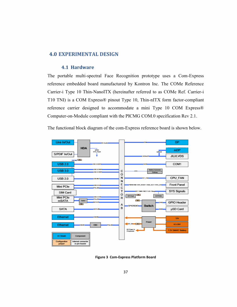
4.1 Hardware
The portable multi-spectral Face Recognition prototype uses a Com-Express
reference embedded board manufactured by Kontron Inc. The COMe Reference
Carrier-i Type 10 Thin-NanoITX (hereinafter referred to as COMe Ref. Carrier-i
T10 TNI) is a COM Express® pinout Type 10, Thin-nITX form factor-compliant
reference carrier designed to accommodate a mini Type 10 COM Express®
Computer-on-Module compliant with the PICMG COM.0 specification Rev 2.1.
The functional block diagram of the com-Express reference board is shown below.
Figure 3 Com-Express Platform Board

38
The com-Express Kontron reference board provides a high-performance Intel Atom
Processor with Apollo-Lake 64-bit version, SPI BIOS socket for SPI flash with up
to 8MB flash memory, 32 Kbits of EEPROM, one digital display interface [DDIO],
a 24-Bit Single Channel LVDS, Mini Display Port.
The details of the system PCIe interfaces, USB interfaces, SATA interfaces,
Gigabit Ethernet interfaces, Micro SD/SIM interface, SYS signal interface,
connectors and power supply management are described in Appendix A.
4.1.1 JAI-AD-080GE Camera
The AD-080GE is a Multi-spectral 2-channel CCD camera with Advanced series 2
x 1/3” progressive scan, can simultaneously capture Visible and Near-IR through
the same optical path with 1024 (h) x 768 (v) active pixels per channel, 30
frames/second with full resolution [ Increased frame rate with partial scan].
AD-080-GE also provides auto-iris lens video output allows a wider range of light,
RGB 24-bit/30-bit or Raw Bayer 10 or 8-bit output for visible 12, 10 or 8-bit output
for Near-IR.
4.2 Hardware BSP Linux X86
The embedded Kontron board is provisioned with community enterprise operating
system [CentOS 7.3]. A custom kernel is built with appropriate drivers enabled in
kernel configuration file. Basic infrastructure is taken from CentOS distribution and
installed on to target.
The embedded target also requires a graphical user interface to perform several face
recognition tasks such as image feature extraction using OpenCV. Hence a KDE
Desktop is installed on the target. The details of CentOS server installation are
given in Appendix B.
The details of KDE Desktop Workspace installation are given in Appendix C.

39
KDE Desktop Environment starts like follows:
Figure 4 KDE Desktop
4.3 OpenCV Installation
OpenCV, also known as Open Source Computer Vision Library, is an open source
cross-platform computer vision algorithm library. Nowadays, OpenCV is being
widely used in all kinds of visual processing areas, such as facial recognition,
gesture recognition, human-computer interaction, object identification, motion
tracking, etc.
OpenCV can be deployed on various platforms, including Windows, Linux,
Android, iOS, etc. The details of the compilation and installation of OpenCV 3.3.0,
the latest stable release of OpenCV on Kontron Target, on the CentOS 7 x64
operating system is given in Appendix D.

40
4.4 MySQL Client Development
A C++ connector client is developed and is used in multi spectral Face Recognition
enrollment process. During enrollment, the client is instantiated and is
automatically connected to SQL server which was installed [explained in later
section MySQL Server Configuration].
A C++ file “mysqlmsfrDBClient.cpp” is developed using a pre-installed SQL
connector-C++. This file uses standard C++ headers and MySQL Connector
specific headers. The software source details are provided in Appendix E.
4.5 MySQL Server Configuration
The multispectral face recognition prototype is inbuilt with a MySQL server for
storing the subject information. The server holds the subject first name, last name, a
unique ID number and the date of registration into the database.
The target is installed with open-source MySQL server packages and the
installation and operational details are described in Appendix F.
4.6 Pleora eBUS SDK
4.6.1 Target System Requirement
The embedded X86 Kontron target meets the following requirements for the
installation of eBus SDK.
At least one Gigabit Ethernet NIC (if you are using GigE Vision devices) or
at least one USB 3.0 port (if you are using USB3 Vision devices).
Appropriate development tool chains or integrated development
environment IDE.
gcc 4.4.7 (or later) to compile non-GUI samples
QMake version 2.01a, with Qt version 4.6.2 to compile GUI-based samples

41
Kernel-devel package for your specific kernel version to compile the eBUS
Universal Pro for Ethernet filter driver.
Centos 7.3 64-Bit.
4.6.2 Tool Requirements
The eBUS SDK uses the standard development tools available for the supported
Linux distributions. The eBUS Universal Pro for Ethernet filter driver requires the
kernel development package and gcc to compile. These can be installed using the
Yum package updater, by executing yum install gcc and yum install kernel-devel,
respectively. The sample applications require the gcc-c++ package for compilation,
which can be obtained by executing yum install gcc-c++. Sample applications with
GUI elements require Qt version 4.6.2 for compilation, which can be installed
using yum install qt-devel.
4.6.3 Installing the eBUS SDK for Linux
1. Log in as superuser.
2. Execute ./eBUS_SDK__<version>_RHEL-6-<architecture>.run where
<architecture is either i686 for 32-bit operating systems or x86_64 for 64-
bit operating systems.
3. During the installation, the script will ask if you would like to:
Add the eBUS SDK and GenICam libraries to the list of shared
libraries available on the system using the ldconfig utility. The
default answer is yes.
Compile the eBUS Universal Pro for Ethernet filter driver, which is
used to optimize the operation of GigE Vision devices. If the kernel
development and gcc packages have been installed, the driver can be
compiled. If not, the script fails.
If you skip the prompt to compile the driver or if the script fails, you
can build it later by running the module/build.sh script.

42
Note: If the eBUS Universal Pro for Ethernet driver is not loaded, you can still
work with GigE Vision devices. However, until you load the driver, the operation
of these devices is not optimized.
4.6.4 Install and run eBUSd
As superuser, execute the bin/install_daemon.sh script and follow the prompts.
You can manually control the state of the daemon by issuing service eBUSd
<command> (where <command> can be start, stop, restart, or status) as superuser.
Enabling Jumbo Ethernet Frames
If supported by your network card, GigE Vision device, and switch (if applicable),
we recommend that you enable jumbo Ethernet frames when using GigE Vision
devices. The use of jumbo frames reduces the amount of Ethernet, IP, UDP, and
GVSP packet overhead when transmitting images, which reduces the CPU load and
memory requirements.
To enable jumbo packets
•As superuser, execute the following command:
/sbin/ifconfig eth[INDEX] mtu [SIZE]
where, [INDEX] = 0,1,2,…,n (depending on the number of NICs present)
[SIZE] = desired frame size
For example,
/sbin/ipconfig eth0 mtu 8000
To increase the socket buffer size
As superuser, execute the bin/set_socket_buffer_size.sh script. To further improve
performance, you can also increase the size of the socket buffer.

43
4.6.5 Compiling and Running Sample Applications
The sample applications require the gcc-c++ package for compilation, which can be
obtained by executing yum install gcc-c++. To build all of the samples, execute the
build.sh script in the share/samples directory.
To compile specific samples, navigate to the folder for the sample within
share/samples and execute the make command.
Compilation will fail for GUI-based samples if the Qt development package
is not installed.
Environment variables must be properly set before any of the compiled
samples are executed. To do this, source the bin/set_puregev_env script by
executing source set_puregev_env or. set_puregev_env.
4.6.6 Pleora Software Development
Several data structures are being used from Pleora software Development kit.
Common classes are listed below:

44

45
For complete list of API class description, refer Pleora Application Programming
Interface [13].
4.7 Enrollment Process
In my research work, we used the open source tools such as Pleora Camera
Interface and Aravis tools to study the continuous stream provided by AD-080GE
Camera. Pleora provides Linux open source SDK which can be used to study the
video results. Aravis provides open source which can be installed and test a generic
GenI Camera or GigE compliance cameras. Pleora requires economical commercial
license for each Gigabit Ethernet Interface to use the tool. Aravis open source is
completely free and being supplied under Apache 2.0 License. Both Pleora and
Aravis requires dhcp server running all the time to assign the IP addresses to AD-
080-GE Camera.
The details of DHCP server installation is described in Appendix G.
4.8 Pleora Camera Interface
Ensure the computer or embedded ARM target meets the following recommended
requirements:
For the x 86 Linux platforms:
At least one Gigabit Ethernet NIC (if you are using GigE Vision devices) or
at least one USB 3.0port (if you are using USB3 Vision devices).
Appropriate development tool chains or integrated development
environment (IDE).
gcc 4.4.7 (or later) to compile non-GUI samples

46
QMake version 2.01a, with Qt version 4.6.2 to compile GUI-based samples
Kernel-devel package for your specific kernel version to compile the eBUS
Universal Pro for Ethernet filter driver
One of the following operating systems:
Red Hat Enterprise Linux7, 64-bit CentOS 7, 64-bit Ubuntu 14.04 LTS and 16.04
LTS, 32-bit or 64-bit
Note: If you plan on using H.264 encoding on the x86 Linux operating system, you
must install some external libraries, enable the H.264 encoding functionality, and
recompile the eBUS Player sample application. For more information, see the
eBUS SDK C++ API Quick Start Guide, which is available on the Pleora Support
Center (www.pleora.com).
For the Linux for ARM platform:
Appropriate cross-compile development tool chains: ARM gnu cross-
compile tool chain 4.8 (or later) Glibc version 2.19 or later. Please note that
other C library implementations, such as uClibc and eglibc, are not
supported.
Linux kernel version 3.1 or later. Net filter kernel configuration must be
enabled before you compile the eBUS Universal Pro for Ethernet filter
driver.
Linux Ubuntu 14.04 LTS development host (or later) is recommended for
manual installation of the eBUS SDK on your ARM board.
On the Linux ARM platform, it is important that you have the correct tool
chain, which is often provided by the board manufacturer. Ensure that the
development board is configured, loads Linux, and the user can transfer
files from the development computer to the target board.

47
See the eBUS SDK release notes for tested configurations.
For Linux ARM platform users, Pleora recommends that before you begin
installation, you take note of the gnu eabi tool chain that is used to compile objects.
You will be required to select the proper .run file for your tool chain during
installation.
For example, eBUS_SDK-<version>-linux-gnueabi-arm.run is for soft-float targets
and eBUS_SDK-<version>-linux-gnueabihf-arm.run is for hard-float targets. The
eBUS SDK uses the standard development tools available for the supported Linux
distributions. The eBUS Universal Pro for Ethernet filter driver requires the kernel
development package and gcc to compile.
These can be installed using the Yum package updater, by executing yum install
gcc and yum install kernel-devel, respectively. The sample applications require the
gcc-c++ package for compilation, which can be obtained by executing yum install
gcc-c++. Sample applications with GUI elements require Qt version 4.6.2 for
compilation, which can be installed using yum install qt-devel.
The eBUS SDK installation procedure is described in Appendix H.
4.9 Aravis Software Installation
Aravis is a glib/gobject based library for video acquisition using GenICam
cameras. It currently only implements an ethernet camera protocol used for
industrial cameras. Aravis is released under the LGPL v2+. Aravis has been tested
successfully with Basler, AlliedVision, Smartek and Dalsa cameras.
Aravis provides open source to interface with GigE vision Cameras. My thesis uses
commercial SDK from Pleora. A significant implementation is done on embedded
target for multi camera detection with minimal changes in software.
The details of Aravis installation is described in Appendix I.

48
4.10 Block Diagram
Figure 5 Block Diagram

49
5.0 ENROLLMENT SOFTWARE DESIGN
Pleora Software Development Kit Application Programming Interface Library is
used to acquire images from both visible and NIR channels of AD-080-GE Camera.
A database is designed to register different subjects using MySQL. MySQL server
installation is performed with user name and a password. MySQL Client will
access the database using MySQL 8.0 Connector using C++. The software is
capable of creating basic database called “msfr Database” with a Password of
“Baxxer@xxx”, insert into Database, Delete/Drop a Database. The images are
stored in MySQL server.
Standalone application software is developed using C++ in CentOS Linux
environment. The application software is capable of detecting all GigE Cameras
connected in the same network. The Camera channels of AD-080-GE Cameras are
connected automatically without any manual intervention and are ready to acquire
the images upon user commands.

50
The below diagram shows the architecture of the enrollment process.
Figure 6 Enrollment Architecture

51
The following software modules are created.
1. acquireImages.cpp
2. Makefile
3. msfrCamera.cpp
4. msfrCamera.h
5. msfrVisAquirekeyctrl.cpp
6. userInput.cpp
7. userInput.h
8. common.h
9. mysql_connection.h
10. mysql_driver.h
11. mysqlmsfrDBClient.cpp
12. xapi.h
13. Xdevapi.h

52
6.0 EXPERIMENTAL RESULTS
In this section, we first briefly explain the settings made on camera lens, distance
from the subject and the alignment of face images. After that the results are
presented and discussed.
6.1 Alignment
I used Pleora eBUS Player in continuous acquisition mode, which enables to see
the live stream of the camera. The images are acquired in single channel RGB
mode and aligned based on the available lens focal length at FIT Biometrics Lab.
Since the AD-080-GE camera has two sensors which can be triggered
simultaneously, an alignment can be set without turning on NIR source.
6.2 Selected Parameters
The current lens used for this experiment is having a focal length of 18mm. I was
unable to get full picture as the field of view and region of interest is small. The
images are acquired at working distance of 16 inches maximizing the region of
interest and found that the both NIR and RGB images are aligned. We also
determined that a new lens with a focal length of 4.8mm will be able to get the full
picture with larger region of interest.
Device parameters for eBUS player are set using the Device Control window
accessed from the Parameters and Controls panel on the main eBUS Player
window. Image stream parameters are set using the Image Stream Control window
accessed from the Parameters and Control panel of the main eBUS Player window.
eBus Player settings are accessed from Tools Menu of the eBUS Player main
window. Using the Tools menu, we set the following parameters:
eBUS Player role and stream destination
Image filtering

53
Deinterlacing
Image saving
Event Monitor
Buffer Options
Display Options
To save device settings to a .pvcfg file on your computer
1. After you have changed settings on the device using eBUS Player, select Save
As from the File menu.
2. Choose a file name and location on your computer to save the .pvcfg file.
3. Click Save.
To apply a saved .pvcfg file to the device
1. Connect to the device using eBUS Player.
2. Select Open from the File menu.
3. Navigate to the saved .pvcfg file and click Open.
Note: You can apply the settings in the saved .pvcfg file to a device with a different
MAC address or GUID.
Using Tools > Save Preferences
When you select Save Preferences on the eBUS Player Tools menu, specific
eBUS Player application settings along with Communication control options,
such as a specific heartbeat interval and answer timeout value, are saved to

54
embedded Linux operating system user profile which is root/admin in our case.
When you next open eBUS Player, your preferences are the same as when you
closed the application with the same user/root profile.
IMP NOTE:
eBUS Player is only used to perform preliminary settings like adjusting
distance, aperture and alignment of the subject with respect to the camera.
The practical sample extraction is performed using custom built C++
application written for GigE interface using Pleora Application
Programming Interface functions.
6.3 Experiments and Results
The experimental setup is shown below:
Figure 7 Experimental Setup

55
The following experiments are performed on embedded prototype:
Device Detection
Single Channel Sample Acquisition
Multi-Channel Sample Acquisition
Device Detection
The MSFR prototype is connected to a Gigabit Ethernet switch and powered
up. The DHCP server is started upon power on reset. I connected DFK 33G618
“The Imaging Source” camera to a Gigabit Ethernet switch. DHCP server assigns
an IP address based on it configuration which is set to 192.168.1.10. I was able to
ping the DFK 33G618 camera and able to acquire the single channel images using
the Enrollment software implemented.
Single Channel Sample Acquisition
The MSFR prototype is connected to a Gigabit Ethernet switch and
powered up. The DHCP server is started upon power on reset. I connected DFK
33G618 “The Imaging Source” camera to a Gigabit Ethernet switch. DHCP server
assigns an IP address based on it configuration which is set to 192.168.1.10. I was
able to ping the DFK 33G618 camera.
Run the executable “msfrEnrollment” from the directory:
/home/pleora/msfrEnrollment. The executable will give you a user input
prompts for following.
Enter insert, edit or delete option for user. The user will select an option to
insert a new dataset sample by pressing “I” or “i”. User inputs first name, last
name, Unique ID. The Enrollment software creates a dedicated subject directory

56
with first of letter of first name, last name and current date. The SQL server is
updated with subject information.
By keep pressing “Enter” key, we can take as many samples as needed and
can be terminated using an “ESC” key.
In single channel acquisition mode, only RGB images are acquired using
DFK 33G618. I also used the AD-080-GE camera single channel mode and able to
acquire the RGB images and a sample of RGB image along with is shown below.
Multi-Channel Sample Acquisition
The MSFR prototype is connected to a Gigabit Ethernet switch and
powered up. The DHCP server is started upon power on reset. MySQL server is
also started. I connected JAI AD-080-GE camera to a Gigabit Ethernet switch.
The DHCP server is started using the command “systemctl start
dhcpd.service”. DHCP server can be stopped using the command “systemctl
stop dhcpd.service”. DHCP Server status can be checked using “systemctl
status dhcpd.service”. The command execution outputs are as shown below
from the actual embedded target execution.
DHCP server assigns an IP addresses based on it configuration which is set
to 192.168.1.10 and 192.168.1.11.
The RGB channel of JAI AD-080-GE camera is assigned with
192.168.1.10.
The NIR channel of JAI AD-080-GE camera is assigned with 192.168.1.11.
Both channels are being tested from command line and appropriate IP
packet buffer are set to receive the jumbo packets through IP as mentioned
in GigE standard interface.

57
SQL server is started is using the command “systemctl start mysql”. This
will enable the MySql server to listen to incoming MySql client connection.
Run the executable “msfrEnrollment” from the directory
/home/pleora/msfrEnrollment. The executable will give different prompts to
user to input information about subject.
Enter insert, edit or delete option for user. The user will select an option to
insert a new dataset sample by pressing “I” or “i”. User inputs first name,
last name, Unique ID. The Enrollment software creates a dedicated subject
directory with first letter of first name, last name and current date. The SQL
server is updated with subject information.
By keep pressing “Enter” key, we can take as many samples as needed and
can be terminated using an “ESC” key.
Each time “msfrEnrollment” executable is run, it creates an independent
subject directory with associated images. The directory of subjects is
located under /home/images folder. The subdirectories contain the
individual NIR and RGB images taken during enrollment process.
All the above steps are performed on the embedded target using the below
commands. The user needs to set the IP address of the target followed by
starting all the services.
# ifconfig enp0s31f6 192.168.1.1/24 up
# systemctl start mysqld
# systemctl restart dhcpd.service
# source /opt/pleora/ebus_sdk/RHEL-CentOS-7-x86_64/bin/set_puregev_env
# systemctl status mysqld

58
# systemctl status dhcpd.service
# source /opt/pleora/ebus_sdk/RHEL-CentOS-7-x86_64/bin/set_puregev_env
#. /msfrEnrollment ## this executes the enrollment process.
A sample RGB image is shown below.
Figure 8 Visible RGB Image

59
The NIR image is shown below.
Figure 9 NIR Image
The embedded prototype designed in this thesis proved that the system is capable
of acquiring perfectly aligned registered images from NIR and Visible channels of
the JAI camera. The database is storing all the subject information needed for
enrollment.

60
7.0 CONCLUSION
The face recognition problem has been widely addressed in the general context of
biometric applications. The emerging of multispectral imagery and its applications
has contributed in advancing the face recognition. However, many technical and
theoretical challenges have been raised and should be faced to maximize the use of
these images. The imaging system construction and database acquisition need
particular attention.
In the midst of this, the quality of multispectral images is an important factor which
can be influenced by the surrounding conditions particularly the light and
alignment. Thus, enhancing the sensory data is a must. This enhancement involves
providing multispectral information in both visible and NIR regions. We have used
a sensor and designed the embedded target to acquire spectral information for NIR
and visible conditions simultaneously.
Our embedded prototype provides capability of extracting the image
simultaneously from NIR and RGB channels, gain benefit from the additional
aligned spectral information. The images acquired provide additional information
for face recognition algorithms. One of the major encountered issues is that the
price of lens for the camera for this type of application.
The relevant spectral bands which are aligned can be chosen in dimensionality
reduction and consequently alleviating the computation duration which is an
important factor towards building a real-time face recognition system. Our
embedded prototype provides the images which contain these relevant aligned
spectral bands for face recognition algorithms which reduces the computation time.

61
8.0 FUTURE WORK
The usefulness of multispectral image has made it popular in many applications.
This fact has contributed in advancing research activities in this topic. As we stated
throughout this report, enhancing the sensory data is a critical stage toward the
building of reliable and accurate face recognition system.
Possible future expansion of this work is to investigate and propose new algorithms
and also investigate further in below mentioned topics.
A live capture of image stream can be setup using multiple cameras and
acquire the images. Existing enrollment software along with prototype will
give an opportunity to register several subjects in the MySQL Database.
Setting up Multi camera system and processing the feature extraction,
template generation can be implemented to extend this project.
Implementing face recognition algorithms or using existing open source
algorithms like VGG Net for Face recognition for real DoD or commercial
applications.
An USB based Wi-Fi module can be integrated to existing hardware to
extend the capabilities of this prototype to get connected to a remote server.
In this MSFR project, I used the third-party vendor Pleora Application
programming interface routines to interface with AD-080-GE camera and
the Imaging source Camera. The API software cost $100 per unit for
licensing. An open source called “Aravis” is available and can be extended
to interface with GenICam or GigE Interfaces. I was able to make progress
on this open source and performed the detection of Cameras. The open
source software has to be modified to implement the enrollment process.

62
The prototype is based on Intel X86_64-bit platform. The hardware is
working on basic desktop power supply providing different power voltages
to embedded platform like 5v, 3.3volts. Keeping a prototype with huge
power demand in the field is not a viable solution. In future the prototype
can be developed using an ARM core platform which provides significantly
reduced power demands and can be operated on a custom-built battery.
The same prototype can be extended to develop IRIS recognition.

63
9.0 References
1. Jain, Anil K., Arun Ross, and Salil Prabhakar. "An introduction to biometric
recognition." IEEE Transactions on circuits and systems for video technology 14.1
(2004): 4-20.
2. Cai, Deng, et al. "Orthogonal laplacianfaces for face recognition." IEEE transactions
on image processing 15.11 (2006): 3608-3614.
3. Schaul, Lex, Clément Fredembach, and Sabine Süsstrunk. "Color image dehazing
using the near-infrared." Proc. IEEE International Conference on Image Processing
(ICIP). No. LCAV-CONF-2009-026. 2009.
4. Bernhard, John, et al. "Near-IR to visible light face matching: Effectiveness of pre-
processing options for commercial matchers." Biometrics Theory, Applications and
Systems (BTAS), 2015 IEEE 7th International Conference on. IEEE, 2015.
5. Uzair, Muhammad, Arif Mahmood, and Ajmal Mian. "Hyperspectral face recognition
with spatiospectral information fusion and PLS regression." IEEE Transactions on
Image Processing 24.3 (2015): 1127-1137.
6. Guo, Kai, Shuai Wu, and Yong Xu. "Face recognition using both visible light image and
near-infrared image and a deep network." CAAI Transactions on Intelligence
Technology 2.1 (2017): 39-47.
7. Hu, Shuowen, et al. "Heterogeneous face recognition: recent advances in infrared-to-
visible matching." Automatic Face & Gesture Recognition (FG 2017), 2017 12th IEEE
International Conference on. IEEE, 2017

64
8. Le, Ha A., and Ioannis A. Kakadiaris. "UHDB31: A dataset for better understanding
face recognition across pose and illumination variation." Computer Vision Workshop
(ICCVW), 2017 IEEE International Conference on. IEEE, 2017.
9. Qi, Xianbiao, and Lei Zhang. "Face Recognition via Centralized Coordinate Learning."
arXiv preprint arXiv:1801.05678 (2018).
10. Li, Stan, et al. "The casia nir-vis 2.0 face database." Proceedings of the IEEE
Conference on Computer Vision and Pattern Recognition Workshops. 2013.
11. Roesch, A., et al. "Comparison of spectral surface albedos and their impact on the
general circulation model simulated surface climate." Journal of Geophysical
Research: Atmospheres 107.D14 (2002).
12. Kong, Seong G., et al. "Recent advances in visual and infrared face recognition—a
review." Computer Vision and Image Understanding 97.1 (2005): 103-135.
13. https://www.pleora.com
14. https://www.springer.com/us/book/9783319284996

65
10.0 Appendix
10.1 A Kontron Embedded Board Interfaces
The reference board provides three PCIe interfaces:
PCIe#0 for Mini PCIe 2.0 half-size card slot connected to the microSD/SIM
combo socket, J28
PCIe#1 for Mini PCIe 2.0 full-size card slot muxed with SATA#1
(mSATA) and connected to the microSD/SIM combo socket, J26
PCIe#2 for the onboard Gigabit Ethernet controller
The Com-Express board provides two SATA 3 Gb/Sec interfaces:
SATA#0 via the 22-pin SATA plug connector, J1
SATA#1 for the mSATA socket / Mini PCIe full-size card slot, J26
The Com-Express board provides two Gigabit Ethernet interfaces:
GbE#0 on RJ45 connector, J4, via COMe mini Type 10 module
GbE#1 on RJ45 connector, J7, via the onboard GbE controller (Intel®
Ethernet Controller I210-IT)
The Com-Express board provides eight USB 2.0 interfaces:
Two USB 2.0 interfaces (USB#[0;1]) for USB 3.0/2.0 double-stack
connector, J9
Two USB 2.0 interfaces (USB#[2;3]) for USB 2.0 double-stack connector,
J13
One USB 2.0 interface (USB#4) for PCIe#0 (Mini PCIe half-size interface)

66
One USB 2.0 interface (USB#5) for PCIe#1 (Mini PCIe full-size/mSATA
interface)
Two USB 2.0 interfaces (USB#[6;7]) for USB 2.0 pin header, J10
The Com-Express board provides two USB 3.0 interfaces:
Two USB 3.0 interfaces (USB_SS#[0;1]) for USB 3.0/2.0 double-stack
connector, J9
The Com-Express board provides three HD Audio Interfaces:
Rear panel line-in connector, J22
Rear panel SPK/line-out connector, J23
S/PDIF header, J24
The Com-Express provides one RS-232 COM port (RX/TX only) for debug
purposes.
Pin header J8
The Com-Express board provides GPIO/SDIO:
Either four GPIs or four GPOs via the 10-pin GPIO pin header, J11, or
alternatively SDIO usage via microSD/SIM combo socket.
The Com-Express board provides an SMBUS and an I2C bus.
I 2C interface via 15-pin SYS_Signals/embedded interfaces pin header, J6
SMBus interface via 15-pin SYS_Signals/embedded interfaces pin header,
J6
The Com-Express board provides two status LEDs.

67
Two status LEDs available via the front panel connector, J5:
Power LED
HDD Activity LED
PCI Express Interfaces
The COMe Ref. Carrier-i T10 TNI provides three general-purpose PCI Express
(PCIe) lanes:
» PCIe#0 for the Mini PCIe half-size card slot, J28, connected to the microSD/SIM
combo socket, J20 » PCIe#1 for Mini PCIe full-size card slot, J26, muxed with
SATA#1 (mSATA), connected to the microSD/SIM combo socket, J20. Mini PCIe
may be enabled via the onboard DIP switch SW1. » PCIe#2 for onboard Gigabit
Ethernet Controller, U23 Note: The MiniPCIe half-size card slot, J28, is available
as a standard feature on the COMe Ref. COMe Ref. Carrier-i T10 TNIV (Value)
and the COMe Ref. Carrier-i T10 TNIP (Professional) versions.
SATA Interfaces
The COMe Ref. Carrier-i T10 TNI supports up to two SATA 3 Gb/s interfaces:
» SATA#0 via the 22-pin SATA plug connector, J1 » SATA#1 for the mSATA
socket / Mini PCIe full-size card slot, J26, muxed with PCIe#1 (Mini PCIe).
mSATA may be enabled via the onboard DIP switch, SW1.
Gigabit Ethernet Interfaces
The COMe Ref. Carrier-i T10 TNI provides up to two Gigabit Ethernet interfaces
via two single RJ45 connectors:
» GBE#0 on RJ45 Ethernet connector, J4, directly via the COMe mini Type 10
module » GBE#1 on RJ45 Ethernet connector, J7, via the onboard Intel® Ethernet
Controller I210-IT, U23 (on PCIe#2)

68
The Ethernet connector LEDs has the following states: LINK (green): Ethernet
Link ACT (green): 1000BASE-T Ethernet Speed ACT (yellow): 100BASE-TX
Ethernet Speed ACT (off) + LINK (on): 10BASE-T Ethernet Speed
Note: The RJ45 Ethernet connector, J7, and the Intel® Ethernet Controller I210-IT,
U23, are available as a standard feature on the COMe Ref. Carrier-i T10 TNIV
(Value) and the COMe Ref. Carrier-i T10 TNIP (Professional) versions.
USB 2.0 Interfaces
The COMe Ref. Carrier-i T10 TNI supports eight high-speed USB 2.0 interfaces
used as host by default:
» USB# [0; 1] are used for USB 3.0/2.0 double-stack connector, J9. 5V standby
power for wake events may be enabled and disabled via the onboard DIP switch,
SW1.
» USB# [2; 3] are routed to the USB 2.0 double-stack connector, J13. 5V standby
power for wake events may be enabled and disabled via the onboard DIP switch,
SW1.
» USB#[4] is used for the Mini PCIe half-size interface to enable usage of USB 2.0
high-speed Mini PCIe form factor devices. » USB#5 is used for the Mini PCIe full-
size / mSATA interface to enable usage of USB 2.0 highspeed Mini PCIe form
factor devices.
» USB# [6; 7] are used for the USB 2.0 pin header, J10. USB#7 can be used as
host or client (switchable via the onboard DIP switch SW1).
USB 3.0 Interfaces
The COMe Ref. Carrier-i T10 TNI supports two super-speed USB 3.0 interfaces
used as host:

69
» USB_SS# [0; 1] are routed to the USB 3.0/2.0 double-stack connector, J9.
HD Audio Interfaces
The COMe Ref. Carrier-i T10 TNI provides HD Audio via the industrial grade HD
Audio Codec IDT / Tempo Semi 92HD73C (U29) through the following analog
and digital audio connectors:
» Rear panel line-in connector, J22 » Rear panel SPK / line-out connector, J23 »
S/PDIF header, J24
MicroSD/SIM Interface
The COMe Ref. Carrier-i T10 TNI provides a microSD/SIM combo socket, J20,
connected to both Mini PCIe interfaces, PCIe#0 and PCIe#1, to support radio-based
services on Mini PCIe.
SYS_Signals / Embedded Interfaces
On the COMe Ref. Carrier-i T10 TNI, a pin header for various SYS_Signals /
embedded interfaces, J6, is available and provides access to the following I/Os:
I2C
SMBus
Watchdog
LID
SLEEP
PIN Header J6 Connector Details:

70
FRONT PANEL INTERFACE
The COMe Ref. Carrier-i T10 TNI provides a front panel connector, J5, with
access to the following signals:
» HDD activity LED » Power LED » Power button » Reset button » Speaker -out
(Beep)
The following figure and table provide pinout information for the front panel
connector J5.

71
FRONT PANEL CONNECTOR J5
DIP Switch
The COMe Ref. Carrier-i T10 TNI provides one 8-position DIP switch, SW1, for
board configuration.
DIP Switch SW1

72
The default setting is indicated by using italic bold.
Power Supply and Management
The COMe Ref. Carrier-i T10 TNI supports fixed input voltage (12V only) as a
standard feature via the DC jack, J21.
10.2 B Network Infrastructure CentOS server installation
Follow the below procedure to install CentOS distribution on Kontron ComExpress
prototype developed for Multispectral Face Recognition.
Connect a USB keyboard and mouse to the USB port of the Kontron Module.
Connect a display to the Display Port of the Kontron Module
Connect a USB DVD Drive to the USB port of the Kontron Module. Power
On.
Insert CentOS Installation disc into the DVD Drive.
Reboot into the BIOS by pressing the delete key repeatedly during the boot up
process until the BIOS screen is visible

73
Go to the Boot menu and make sure Boot Option 1 is USB device and Boot
Option 2 is CD/DVD.
Go to “Save Changes and Reset”
Once it resets, choose “Install CentOS 7”
Click on English as the language and continue.
Click on “Software Selection” under the SOFTWARE category.
Choose “Infrastructure Server” under Base Environment
Choose the following software tools as Add-Ons for the selected environment
and click done.
Debugging Tools
FTP Server
File and Storage Server
Hardware Monitoring Utilities
Java Platform
Large System Performance
Maria DB Database Server
Network File System Client
Performance Tools
PostgreSQL Database Server
Remote Management for Linux
Virtualization Hypervisor
Compatibility Libraries
Development Tools
Security Tools
Smart Card Support
Click on Installation Destination under SYSTEM category.
Select the option “Automatically configure partitioning” and check “I would
like to make additional space available” and click done.

74
A new window should pop up with the option to Reclaim Space. Click on
“Delete all” if a partition already exists and then click on “Reclaim Space.”
Click “Begin Installation” after returning to Installation Summary page.
While it installs, set the root password to “Banner@567”.
Wait for installation to finish and click “Reboot.” Cycle the power.
The DVD drive should open automatically. Retrieve the DVD and let it reboot.
10.3 C KDE Plasma Workspace Installation
Install KDE Desktop Environment on the embedded target using the following
command.
# yum -y groups install “KDE Plasma Workspaces”
Input a command like below after installing all the required packages along with
dependencies.
#echo “exec startkde” >> ~/.xinitrc
# startx
# systemctl set-default graphical.target
Removed symlink /etc/systemd/system/default.target.
Created symlink from /etc/systemd/system/default.target to
/usr/lib/systemd/system/graphical.target.
# systemctl get-default
Graphical.target
10.4 D OpenCV Target Installation
OPENCV Install Instructions for LINUX.
#cd /home

75
#mkdir -p opencv
git clone https://github.com/opencv/opencv.git
Prerequisites
A CentOS 7 x64 server instance.
Logging in as root.
The server instance has been updated to the latest stable status.
Step 1: Install dependencies for OpenCV
Use the following commands to install all required dependencies for compiling
OpenCV:
# yum groupinstall "Development Tools" -y
# yum install cmake gcc gtk2-devel numpy pkconfig -y
Step 2: Download the OpenCV 3.3.0 archive
Download and uncompress OpenCV 3.3.0 archive as below:
cd
# wget https://github.com/opencv/opencv/archive/3.3.0.zip
# unzip 3.3.0.zip
Step 3: Compile and install OpenCV 3.3.0

76
Use the following commands to compile and install OpenCV, and compiled
OpenCV files will be saved in the /usr/local directory.
# cd opencv-3.3.0
# mkdir build
# cd build
# cmake -D CMAKE_BUILD_TYPE=DEBUG -D
CMAKE_INSTALL_PREFIX=/usr/local ..
# make
# make install
Step 4: Configure required variables
In addtion to compiling and installing files, you need to specify path info for
pkgconfig and OpenCV:
#export PKG_CONFIG_PATH=$PKG_CONFIG_PATH:/usr/local/lib/pkgconfig/
# echo '/usr/local/lib/' >> /etc/ld.so.conf.d/opencv.conf
# ldconfig
Step 5 (optional): Run tests
To test your OpenCV installation, you can download extra test data from OpenCV
extra repository:
cd
git clone https://github.com/opencv/opencv_extra.git
export OPENCV_TEST_DATA_PATH=/root/opencv_extra/testdata

77
In the cmake build directory, you will find several test executables named in the
same kind of format opencv_test_*. Run any one you are interested in to perform a
test. For example:
cd /root/opencv-3.3.0/build/bin
ls
# ./opencv_test_photo
[root@pgcentos build]#
[root@pgcentos build]# pwd
/home/pgopencv/build
[root@pgcentos build]# export
PKG_CONFIG_PATH=$PKG_CONFIG_PATH:/usr/local/lib/pkgconfig/
[root@pgcentos build]# echo '/usr/local/lib/' >>
/etc/ld.so.conf.d/opencv.conf
[root@pgcentos build]# ldconfig
[root@pgcentos build]#
# yum install jasper.x86_64 jasper-devel.x86_64
# yum install qt5-qtgraphicaleffects.x86_64
# yum install qt-config.x86_64
# yum install qt3-config.x86_64
Note: OPENCV 3.4 REQUIRES PYTHON 3.5 LATER.
[root@centos pg]# pwd
/home/pg
[root@pgcentos pg]# wget
http://python.org/ftp/python/3.6.3/Python-3.6.3.tar.xz
[root@pgcentos pg]# tar -xvf Python-3.6.3.tar.xz

78
[root@pgcentos pg]# cd Python-3.6.3/
[root@pgcentos pg]# cd Python-3.6.3/
[root@pgcentos Python-3.6.3]# ./configure --prefix=/usr/local
--enable-shared LDFLAGS="-Wl,-rpath /usr/local/lib"
[root@pgcentos Python-3.6.3]# make
[root@pgcentos Python-3.6.3]#
[root@pgcentos Python-3.6.3]# make altinstall
[root@pgcentos Python-3.6.3]# ls /usr/local/bin/python3.6
/usr/local/bin/python3.6
[root@pgcentos Python-3.6.3]#
[root@pgcentos Python-3.6.3]# wget
https://bootstrap.pypa.io/get-pip.py
--2018-07-06 20:01:08-- https://bootstrap.pypa.io/get-pip.py
Resolving bootstrap.pypa.io (bootstrap.pypa.io)...
151.101.4.175, 2a04:4e42:1::175
Connecting to bootstrap.pypa.io
(bootstrap.pypa.io)|151.101.4.175|:443... connected.
HTTP request sent, awaiting response... 200 OK
[root@pgcentos Python-3.6.3]# python2.7 get-pip.py
# Use the built-in functionality in Python 3.6 to create a
sandbox called my36project:
python3.6 -m venv my36project
# Check the system Python interpreter version:
python --version
# This will show Python 2.6.6
# Activate the my27project sandbox:
source my27project/bin/activate

79
# Check the Python version in the sandbox (it should be
Python 2.7.14):
python --version
# Deactivate the sandbox:
deactivate
# Activate the my36project sandbox:
source my36project/bin/activate
# Check the Python version in the sandbox (it should be
Python 3.6.3):
python --version
# Deactivate the sandbox:
deactivate
[root@pgcentos Python-3.6.3]# pip2.7 install virtualenv
[root@pgcentos Python-3.6.3]#
[root@pgcentos Python-3.6.3]# python3.6 -m venv my36project
[root@pgcentos Python-3.6.3]# python --version
Python 2.7.5
[root@pgcentos Python-3.6.3]# source my27project/bin/activate
(my27project)[root@pgcentos Python-3.6.3]#
(my27project)[root@pgcentos Python-3.6.3]# python --version
Python 2.7.5
(my27project)[root@pgcentos Python-3.6.3]# deactivate
[root@pgcentos Python-3.6.3]#
[root@pgcentos Python-3.6.3]#
[root@pgcentos Python-3.6.3]# source my36project/bin/activate
(my36project) [root@pgcentos Python-3.6.3]#
(my36project) [root@pgcentos Python-3.6.3]#
(my36project) [root@pgcentos Python-3.6.3]# python --version
Python 3.6.3
(my36project) [root@pgcentos Python-3.6.3]#
(my36project) [root@pgcentos Python-3.6.3]#

80
NOTE : I WAS ABLE TO BUILD OPENCV WITH PYTHON 3.6 WITH OUT
ERRORS
[root@pgcentos build]#
[root@pgcentos build]#
[root@pgcentos build]#
[root@pgcentos build]# cmake -D CMAKE_BUILD_TYPE=DEBUG -D
CMAKE_INSTALL_PREFIX=/usr/local ..
-- Found PythonInterp: /usr/local/bin/python3.6 (found
suitable version "3.6.3", minimum required is "3.4")
-- Found PythonLibs: /usr/local/lib/libpython3.6m.so (found
suitable exact version "3.6.3")
-- Configuring done
-- Generating done
-- Build files have been written to: /home/opencv/build
[root@pgcentos build]#
10.5 E Source mysqlmsfrDBClient.cpp
mysqlmsfrDBClient.cpp
/* Standard C++ headers */
#include <iostream>
#include <sstream>
#include <memory>
#include <string>
#include <stdexcept>
/* MySQL Connector/C++ specific headers */
#include <driver.h>
#include <connection.h>
#include <statement.h>
#include <prepared_statement.h>
#include <resultset.h>

81
#include <metadata.h>
#include <resultset_metadata.h>
#include <exception.h>
#include <warning.h>
#define DBHOST "tcp://127.0.0.1:3306"
#define USER "root"
#define PASSWORD "admin"
#define DATABASE "test"
#define NUMOFFSET 100
#define COLNAME 200
The following functions are developed to implement user inputs for database and
updating the same information in MySQL Server Database.
static void retrieve_data_and_print (ResultSet *rs, int type,
int colidx, string colname)
static void retrieve_dbmetadata_and_print (Connection *dbcon)
static void retrieve_rsmetadata_and_print (ResultSet *rs)
int main(int argc, const char *argv[]) {
Driver *driver;
Connection *con;
Statement *stmt;
ResultSet *res;
PreparedStatement *prep_stmt;
Savepoint *savept;
int updatecount = 0;

82
/* initiate url, user, password and database variables */
string url(argc >= 2 ? argv[1] : DBHOST);
const string user(argc >= 3 ? argv[2] : USER);
const string password(argc >= 4 ? argv[3] : PASSWORD);
const string database(argc >= 5 ? argv[4] : DATABASE);
try {
driver = get_driver_instance();
/* create a database connection using the Driver */
con = driver -> connect(url, user, password);
/* alternate syntax using auto_ptr to create the db
connection */
//auto_ptr con (driver -> connect(url, user,
password));
:
:
}
Compile Instructions to build the client Executable:
# g++ -o mysqlmsfrClient -g0 -
I/home/msfrDB/mysqlClient/cppconn -
I/opt/coolstack/mysql_32bit/include/mysql -I/export/ expts/
MySQLConnectorC++/include/cppconn
-L/opt/coolstack/mysql_32bit/lib/mysql -
L/export/expts/MySQLConnectorC++/lib -lmysqlcppconn
mysqlmsfrDBClient.cpp

83
Note : above command must be executed with all options in one
line.
10.6 F MySQL Server Configuration
[root@pgcentos Packages]# yum install mysql-community-
server.x86_64 mysql-community-client.x86_64 mysql-community-
common.x86_64 mysql-community-devel.x86_64 mysql-community-
libs-compat.x86_64 mysql-community-libs.x86_64 mysql-
community-test.x86_64 mysql-connector-c++-devel.x86_64 mysql-
shell.x86_64 mysql-utilities.noarch
Loaded plugins: fastestmirror, langpacks
Loading mirror speeds from cached hostfile
Resolving Dependencies
--> Running transaction check
Installed:
mysql-community-client.x86_64 0:5.7.23-1.el7
mysql-community-common.x86_64 0:5.7.23-1.el7
mysql-community-devel.x86_64 0:5.7.23-1.el7
mysql-community-libs.x86_64 0:5.7.23-1.el7
mysql-community-libs-compat.x86_64 0:5.7.23-1.el7
mysql-community-server.x86_64 0:5.7.23-1.el7
mysql-community-test.x86_64 0:5.7.23-1.el7
mysql-connector-c++-devel.x86_64 0:8.0.12-1.el7
mysql-shell.x86_64 0:8.0.12-1.el7
mysql-utilities.noarch 0:1.6.5-1.el7
Dependency Installed:
mysql-connector-c++.x86_64 0:8.0.12-1.el7 mysql-connector-
c++-jdbc.x86_64 0:8.0.12-1.el7 mysql-connector-python.x86_64
0:8.0.12-1.el7

84
perl-JSON.noarch 0:2.59-2.el7
Replaced:
mariadb-devel.x86_64 1:5.5.56-2.el7
mariadb-libs.x86_64 1:5.5.56-2.el7
Complete!
[root@pgcentos Packages]#
STEP 2: STARTING THE SQL SERVER
[root@pgcentos ~]#
[root@pgcentos ~]#
[root@pgcentos ~]# systemctl start mysqld
[root@pgcentos ~]# systemctl status mysqld
â—• mysqld.service - MySQL Server
Loaded: loaded (/usr/lib/systemd/system/mysqld.service;
enabled; vendor preset: disabled)
Active: active (running) since Thu 2018-08-16 17:15:36
EDT; 12s ago
Docs: man:mysqld(8)
http://dev.mysql.com/doc/refman/en/using-
systemd.html
Process: 6719 ExecStart=/usr/sbin/mysqld --daemonize --pid-
file=/var/run/mysqld/mysqld.pid $MYSQLD_OPTS (code=exited,
status=0/SUCCESS)
Process: 6640 ExecStartPre=/usr/bin/mysqld_pre_systemd
(code=exited, status=0/SUCCESS)
Main PID: 6722 (mysqld)
CGroup: /system.slice/mysqld.service
└─6722 /usr/sbin/mysqld --daemonize --pid-
file=/var/run/mysqld/mysqld.pid

85
Aug 16 17:15:30 pgcentos.localdomain systemd[1]: Starting
MySQL Server...
Aug 16 17:15:36 pgcentos.localdomain systemd[1]: Started
MySQL Server.
[root@pgcentos ~]#
STEP 3: CONFIGURE SQL SERVER
[root@pgcentos ~]#
[root@pgcentos ~]# systemctl stop mysqld
[root@pgcentos ~]#
[root@pgcentos ~]#
[root@pgcentos ~]# grep 'temporary password'
/var/log/mysqld.log
2018-08-16T21:15:31.730842Z 1 [Note] A temporary password is
generated for root@localhost: Ex;gy50buw&p
[root@pgcentos ~]#
[root@pgcentos ~]# mysql_secure_installation
Securing the MySQL server deployment.
Enter password for user root: gy50buw&p
Error: Access denied for user 'root'@'localhost' (using
password: YES)
[root@pgcentos ~]# mysql -uroot -p
Enter password:
Welcome to the MySQL monitor. Commands end with ; or \g.
Your MySQL connection id is 12
Server version: 5.7.23
Copyrightgy (c) 2000, 2018, Oracle and/or its affiliates. All
rights reserved.

86
Oracle is a registered trademark of Oracle Corporation and/or
its
affiliates. Other names may be trademarks of their respective
owners.
Type 'help;' or '\h' for help. Type '\c' to clear the current
input statement.
mysql> flugy50buw&p
sh privileges
-> flush privileges;
ERROR 1064 (42000): You have an error in your SQL syntax;
check the manual that corresponds to your MySQL server
version for the right syntax to use near 'flush privileges'
at line 2
mysql> flush privileges;
ERROR 1820 (HY000): You must reset your password using ALTER
USER statement before executing this statement.
mysql> quit
Bye
[root@pgcentos ~]#
TROUBLE SHOOT THE SQL SERVER DAEMON
[root@pgcentos ~]# find / -type s | grep mysql
[root@pgcentos ~]# ls /var/run/mysqld/
[root@pgcentos ~]# ls -al /var/run/mysqld/
total 0
drwxr-xr-x. 2 mysql mysql 40 Aug 16 17:35 .
drwxr-xr-x. 50 root root 1460 Aug 16 17:11 ..
[root@pgcentos ~]# systemctl restart mysqld
[root@pgcentos ~]# find / -type s | grep mysql
/var/lib/mysql/mysql.sock

87
[root@pgcentos ~]#
TROUBLESHOOTING PASSWORD PROBLEMS IN MYSQL
[root@pgcentos msfrDB]# mysql -u root -p
Enter password:
Welcome to the MySQL monitor. Commands end with ; or \g.
Your MySQL connection id is 4
Server version: 5.7.23
Copyright (c) 2000, 2018, Oracle and/or its affiliates. All
rights reserved.
Oracle is a registered trademark of Oracle Corporation and/or
its affiliates. Other names may be trademarks of their
respective owners.
Type 'help;' or '\h' for help. Type '\c' to clear the current
input statement.
mysql> FLUSH PRIVILEGES;
ERROR 1820 (HY000): You must reset your password using ALTER
USER statement before executing this statement.
mysql> SET PASSWORD FOR 'root'@'localhost' =
PASSWORD('Banner@567');
Query OK, 0 rows affected, 1 warning (0.01 sec)
mysql>
mysql> quit
Bye
[root@pgcentos msfrDB]#
CHECKING SQL VERSION CHECK THE SERVER IS WORKING :

88
[root@pgcentos msfrDB]#
[root@pgcentos msfrDB]#
[root@pgcentos msfrDB]# mysqladmin -u root -p version
Enter password:
mysqladmin Ver 8.42 Distrib 5.7.23, for Linux on x86_64
Copyright (c) 2000, 2018, Oracle and/or its affiliates. All
rights reserved.
Oracle is a registered trademark of Oracle Corporation and/or
its
affiliates. Other names may be trademarks of their respective
owners.
Server version 5.7.23
Protocol version 10
Connection Localhost via UNIX socket
UNIX socket /var/lib/mysql/mysql.sock
Uptime: 13 min 36 sec
Threads: 1 Questions: 11 Slow queries: 0 Opens: 106 Flush
tables: 1 Open tables: 99 Queries per second avg: 0.013
[root@pgcentos msfrDB]#
CREATING A MULTI SPECTRAL DATABASE
[root@pgcentos msfrDB]# mysql -u root -p
Enter password:
Welcome to the MySQL monitor. Commands end with ; or \g.
Your MySQL connection id is 8
Server version: 5.7.23 MySQL Community Server (GPL)

89
Copyright (c) 2000, 2018, Oracle and/or its affiliates. All
rights reserved.
Oracle is a registered trademark of Oracle Corporation and/or
its affiliates. Other names may be trademarks of their
respective owners.
Type 'help;' or '\h' for help. Type '\c' to clear the current
input statement.
mysql>
mysql> CREATE DATABASE msfrDataBase;
Query OK, 1 row affected (0.00 sec)
mysql> SHOW DATABASES;
+--------------------+
| Database |
+--------------------+
| information_schema |
| msfrDataBase |
| mysql |
| performance_schema |
| sys |
+--------------------+
5 rows in set (0.00 sec)
mysql>
# USING msfrDataBase
mysql> USE msfrDataBase;
Database changed
# CREATE A TABLE within the database msfrDataBase

90
mysql> CREATE TABLE DataSet (fname VARCHAR(20), lname
VARCHAR(20), id INT, imagedir VARCHAR(40), signup_data DATE);
Query OK, 0 rows affected (0.03 sec)
mysql>
# SHOWING EXISTING TABLES IN database with name "msfrDataBase
"
mysql> SHOW TABLES;
+------------------------+
| Tables_in_msfrDataBase |
+------------------------+
| DataSet |
+------------------------+
1 row in set (0.00 sec)
mysql>
# INSERTING INFORMATION OF A PERSON INTO DATABASE NAME :
msfrDataBase and TABLE NAME IS : DataSet
mysql> INSERT INTO `DataSet` (`fname`, `lname`, `id`,
`imagedir`,`signup_data`) VALUES ("Vani", "Kolli",
19750210,"/home/msfrDB/VKolli-19750210",'2018-08-16');
Query OK, 1 row affected (0.01 sec)
mysql> SELECT * FROM DataSet;
+-------+-------+----------+------------------------------+--
-----------+
| fname | lname | id | imagedir |
signup_data |
+-------+-------+----------+------------------------------+--
-----------+

91
| Vani | Kolli | 19750210 | /home/msfrDB/VKolli-19750210 |
2018-08-16 |
+-------+-------+----------+------------------------------+--
-----------+
1 row in set (0.00 sec)
mysql>
mysql> quit
Bye
[root@pgcentos msfrDB]#
# VERIFYING THE DATABASE EXISTS EVEN AFTER LOG OUT AND LOG
BACK IN. VERIFICATION :
[root@pgcentos ~]#
[root@pgcentos ~]# systemctl stop mysqld
[root@pgcentos ~]#
[root@pgcentos ~]#
[root@pgcentos ~]# systemctl start mysqld
[root@pgcentos ~]#
# The Password is Banner@567
[root@pgcentos msfrDB]# mysql -u root -p
Enter password:
Welcome to the MySQL monitor. Commands end with ; or \g.
Your MySQL connection id is 9
Server version: 5.7.23 MySQL Community Server (GPL)
Copyright (c) 2000, 2018, Oracle and/or its affiliates. All
rights reserved.

92
Oracle is a registered trademark of Oracle Corporation and/or
its affiliates. Other names may be trademarks of their
respective owners.
Type 'help;' or '\h' for help. Type '\c' to clear the current
input statement.
mysql> SHOW DATABASES;
+--------------------+
| Database |
+--------------------+
| information_schema |
| msfrDataBase |
| mysql |
| performance_schema |
| sys |
+--------------------+
5 rows in set (0.00 sec)
mysql> USE msfrDataBase;
Reading table information for completion of table and column
names
You can turn off this feature to get a quicker startup with -
A
Database changed
mysql> SHOW TABLES;
+------------------------+
| Tables_in_msfrDataBase |
+------------------------+
| DataSet |
+------------------------+
1 row in set (0.00 sec)

93
mysql> SELECT * FROM DataSet;
+---------+--------+----------+------------------------------
-+-------------+
| fname | lname | id | imagedir
| signup_data |
+---------+--------+----------+------------------------------
-+-------------+
| Vani | Kolli | 19750210 | /home/msfrDB/VKolli-19750210
| 2018-08-16 |
| Chandra | Koneru | 20020703 | /home/msfrDB/CKoneru-20020703
| 2018-08-16 |
+---------+--------+----------+------------------------------
-+-------------+
2 rows in set (0.00 sec)
mysql> quit
Bye
[root@pgcentos msfrDB]#
# DELETING A ROW FROM A TABLE
mysql> DELETE FROM DataSet WHERE fname = "London, UK";
Query OK, 1 row affected (0.01 sec)
mysql> SELECT * FROM DataSet;
+---------+--------+----------+------------------------------
-+-------------+
| fname | lname | id | imagedir
| signup_data |
+---------+--------+----------+------------------------------
-+-------------+

94
| Vani | Kolli | 19750210 | /home/msfrDB/VKolli-19750210
| 2018-08-16 |
| Chandra | Koneru | 20020703 | /home/msfrDB/CKoneru-20020703
| 2018-08-16 |
+---------+--------+----------+------------------------------
-+-------------+
2 rows in set (0.00 sec)
mysql> quit
Bye
10.7 G DHCP Server Installation
****** contents of /etc/dhcp/dhcpd.conf file ****************
# dhcpd.conf
#
# Sample configuration file for ISC dhcpd
#
# option definitions common to all supported networks...
option domain-name "example.org";
option domain-name-servers ns1.example.org, ns2.example.org;
default-lease-time 600;
max-lease-time 7200;
# Use this to enble / disable dynamic dns updates globally.
#ddns-update-style none;
# If this DHCP server is the official DHCP server for the local
# network, the authoritative directive should be uncommented.

95
#authoritative;
# Use this to send dhcp log messages to a different log file (you also
# have to hack syslog.conf to complete the redirection).
log-facility local7;
# No service will be given on this subnet, but declaring it helps the
# DHCP server to understand the network topology.
subnet 192.168.1.0 netmask 255.255.255.0 {
range 192.168.1.10 192.168.1.20;
option routers 192.168.1.1;
}
********* END of /etc/dhcp/dhcpd.conf file ******************
********* START OF /etc/sysconfig/dhcpd file ****************
FILE NAME : /etc/sysconfig/dhcpd
$cp /usr/lib/systemd/system/dhcpd.service /etc/systemd/system/
$vi /etc/systemd/system/dhcpd.service
$ExecStart=/usr/sbin/dhcpd -f -cf /etc/dhcp/dhcpd.conf -user dhcpd -group dhcpd --no-pid
<your_interface_name(s)>
$systemctl --system daemon-reload
$systemctl restart dhcpd.service
***************** END OF DHCPD ******************************

96
TO START DHCPD.SERVICE FOLLOW BELOW COMMANDS
[root@localhost ~]# ifconfig enp0s25 192.168.1.1/24 up
[root@localhost ~]# systemctl restart dhcpd.service
[root@localhost ~]#
[root@localhost ~]# systemctl list-dependencies dhcpd | grep dhcp
dhcpd.service
[root@localhost ~]#
************ END OF SERVER CONFIGURATION *********************
************* DHCP CLIENT CONFIGURATION **********************
INCLUDE THE FOLLOWING IN NETWORK CONFIGURTAION FILE :
ONBOOT=yes
BOOTPROTO=dhcp
DEVICE=eth0
to acquire a IP address , run the following command on client machine.
#service network restart
check the IP address with ifconfig -a.. observe the ip address assigned to client.
************ END OF DHCP CLIENT CONFIGURATION ******************
10.8 H Installing the eBUS SDK for the x86 or x64 for Linux
platform
1. Log in as superuser.
2. Execute one of the following commands, depending on the operating system:

97
For Ubuntu:
sudo dpkg -i eBUS_SDK_Ubuntu-<version>.deb
For x64 CentOS or Red Hat Enterprise Linux:
sudo rpm -i eBUS_SDK_CentOS-RHEL-7-x86_64-<version>.rpm
The SDK installs to the /opt/pleora/ebus_sdk/<platform> directory.
Installing the eBUS SDK For the Linux for ARM platform
1. Execute sudo dpkg -i eBUS_SDK_<version>_linux-<architecture>-arm.deb
Where <architecture> is either gnueabihf for hard-float targets or gnueabi for soft-float targets.
The SDK installs to the /opt/pleora/ebus_sdk/linux-<architecture>-arm directory
10.9 I Installation of Aravis on CentOS Embedded Target
Website: https://github.com/AravisProject/aravis
Aravis uses the standard GNU build system, using autoconf for package
configuration and resolving portability issues, automake for building make files
that comply with the GNU Coding Standards, and libtool for building shared
libraries on multiple platforms. The recommended way to get the sources is to
download the release tarballs from
http://ftp.gnome.org/pub/GNOME/sources/aravis.
. /configure
make
make install
Compilation options may be passed to the configure script. Please run. /configure --
help for information about the available options.
On some platforms (like Ubuntu), you may have to configure the dynamic linker
(ld) to let it know where the aravis libraries are installed and run ldconfig as root in
order to update ld cache.

98
If you want to use a clone of the git repository on github, instead of the release
tarballs, you may have to create the configure script by running:
./autogen.sh
Ethernet Device Performance
Stream Packet Size
One way to increase streaming performance is to increase the stream packet size.
arv_camera_gv_set_packet_size() (and arv_camera_gv_auto_packet_size() since
Aravis 0.5.X) allows you to change this parameter. By default, the network adapter
of your machine will probably not let you receive packet bigger than 1500 bytes,
which is the default Maximum Transfer Unit (MTU). It means if you want to use
big packets, you also have to increase the network adapter MTU to a greater walue
(8192 bytes being a recommended value). The exact procedure to change the MTU
depends on the distribution you are using. Please refer to the administrator manual
of your distribution.
Please note if your device is not connected directly to the machine, you may also
have to tweak the active devices on your network.
Packet Socket Support (Since Aravis 0.5.x)
Aravis can use packet sockets for the video receiving thread. But this mode
requires extended capabilities. If you want to allow your application to use packet
socket, you must set the cap_net_raw capability using setcap. For example, the
following command gives this capability to the Aravis viewer (You should do this
on the installed arv-viewer executable, has the one in the source tree is just a
wrapper shell script):

99
sudo setcap cap_net_raw+ep arv-viewer
USB Permissions
By default, USB devices permissions may not be sufficient to allow any user to
access the USB3 cameras. These permissions can be changed by using an udev rule
file. There is a file example in Aravis sources, aravis.rules. This file must be placed
in /etc/udev/rules.d directory (The exact location may depend on the distribution
you are using). This file only contains declarations for a couple of vendors. If you
want to add an entry with the vendor of your camera, the output of lsusb command
will give you the vendor ids, which are the first 4 digits of the ID field.
Dependencies
The Aravis library depends on libxml2 and glib2, with an optional USB support
depending on libusb1, and an optional packet socket support depending on libaudit.
The GStreamer plugin depends on GStreamer1 in addition to the Aravis library
dependencies.
The simple viewer depends on GStreamer1, Gtk+3, libnotify and the Aravis library
dependencies. The required versions are specified in the configure.ac file in Aravis
sources.
It is perfectly possible to only build the library, reducing the dependencies to the
bare minimum. Aravis has a set of unit tests that helps to catch regressions and
memory leaks during the development. The test suite is run using the following
commands:
cd tests
make check
make check-valgrind-memcheck

100
make check-valgrind-hellgrind, make check-valgrind-sgcheck and make check-
valgrind-drd are known to not pass. Any help to understand what fails and why
would be nice.
All the code is not covered yet by the tests. Code coverage can be obtained using:
cd tests
make check-code-coverage
The report is published in tests/aravis-{VERSION}-coverage/index.html. Code
coverage improvment is welcomed as well.
Downloads 0.4.x stable releases:
http://ftp.gnome.org/pub/GNOME/sources/aravis/0.4/
Development releases:
http://ftp.gnome.org/pub/GNOME/sources/aravis/0.5/
Links:
GitHub repository: https://github.com/AravisProject/aravis
Aravis 0.4 documentation:
https://aravisproject.github.io/docs/aravis-0.4/
Aravis 0.5 (unstable) documentation:
https://aravisproject.github.io/docs/aravis-0.5/
Blog: http://blogs.gnome.org/emmanuel/category/aravis/
Genicam standard: http://www.genicam.org

101
STEP 1: DOWNLOAD THE TAR BALL FROM ARAVIS WEBSITE.
THE TAR BALL NAME IS aravis-0.5.0.tar.xz into the folder
home/pg/Aravis
[root@localhost Aravis]#cd Aravis/
[root@localhost home]#unxz aravis-0.5.0.tar.xz
[root@localhost home]#tar -xvf aravis-0.5.0.tar
[root@localhost home]#cd aravis-0.5.0/
[root@localhost aravis-0.5.0]# ls
aclocal.m4 ChangeLog config.sub COPYING gst
INSTALL m4 Makefile.in po tests
aravis.pc.in compile configure depcomp gst-0.10
install-sh Makefile.am missing README.md TODO
AUTHORS config.guess configure.ac docs gtk-
doc.make ltmain.sh Makefile.decl NEWS src
viewer
[root@localhost aravis-0.5.0]# ./configure
checking for a BSD-compatible install... /usr/bin/install -c
checking whether build environment is sane... yes
checking for a thread-safe mkdir -p... /usr/bin/mkdir -p
checking for sys/types.h... yes
checking for a working dd... /usr/bin/dd
checking if g++ static flag -static works... no
checking if g++ supports -c -o file.o... yes
checking if g++ supports -c -o file.o... (cached) yes
checking whether the g++ linker (/usr/bin/ld -m elf_x86_64) supports shared libraries... yes
checking dynamic linker characteristics... (cached) GNU/Linux ld.so
checking how to hardcode library paths into programs... immediate
checking for pkg-config... /usr/bin/pkg-config
checking pkg-config is at least version 0.14... yes
checking for ARAVIS_USB... no

102
checking for ARAVIS... no
configure: error: Package requirements (glib-2.0 >= 2.26 gobject-2.0 gio-2.0 libxml-2.0 gthread-2.0 zlib) were
not met:
No package 'glib-2.0' found
No package 'gobject-2.0' found
No package 'gio-2.0' found
No package 'libxml-2.0' found
No package 'gthread-2.0' found
Consider adjusting the PKG_CONFIG_PATH environment variable if you
installed software in a non-standard prefix. Alternatively, you may set the environment variables
ARAVIS_CFLAGS and ARAVIS_LIBS to avoid the need to call pkg-config. See the pkg-config man page for
more details.
[root@localhost aravis-0.5.0]# yum install glib
Loaded plugins: fastestmirror, langpacks
Bad id for repo: Centos 7, byte = 6
Loading mirror speeds from cached hostfile
* base: mirror.genesisadaptive.com
* extras: centos2.zswap.net
* updates: centos.mirror.constant.com
No package glib available.
Error: Nothing to do
[root@localhost aravis-0.5.0]#
[root@localhost aravis-0.5.0]# yum install libxml2-devel.x86_64
Loaded plugins: fastestmirror, langpacks
Bad id for repo: Centos 7, byte = 6
Loading mirror speeds from cached hostfile
* base: mirror.genesisadaptive.com
* extras: centos2.zswap.net
* updates: centos.mirror.constant.com
Resolving Dependencies
--> Running transaction check
---> Package libxml2-devel.x86_64 0:2.9.1-6.el7_2.3 will be installed
--> Finished Dependency Resolution
Dependencies Resolved

103
===============================================================================
=
Package Arch Version Repository Size
===============================================================================
=
Installing:
libxml2-devel x86_64 2.9.1-6.el7_2.3 base 1.0 M
Transaction Summary
===============================================================================
=
Install 1 Package
Total download size: 1.0 M
Installed size: 8.8 M
Is this ok [y/d/N]: y
Downloading packages:
libxml2-devel-2.9.1-6.el7_2.3.x86_64.rpm | 1.0 MB 00:00
Running transaction check
Running transaction test
Transaction test succeeded
Running transaction
Warning: RPMDB altered outside of yum.
Installing : libxml2-devel-2.9.1-6.el7_2.3.x86_64 1/1
Verifying : libxml2-devel-2.9.1-6.el7_2.3.x86_64 1/1
Installed:
libxml2-devel.x86_64 0:2.9.1-6.el7_2.3
Complete!
[root@localhost aravis-0.5.0]#
[root@localhost aravis-0.5.0]# ./configure
checking for a BSD-compatible install... /usr/bin/install -c
checking whether build environment is sane... yes
checking for a thread-safe mkdir -p... /usr/bin/mkdir -p
checking for gawk... gawk
checking whether make sets $(MAKE)... yes

104
checking whether make supports nested variables... yes
checking whether to enable maintainer-specific portions of Makefiles... no
checking whether make supports nested variables... (cached) yes
checking for style of include used by make... GNU
checking for gcc... gcc
checking whether the C compiler works... yes
checking for C compiler default output file name... a.out
checking for suffix of executables...
checking whether we are cross compiling... no
checking for gtk-doc... no
configure: WARNING:
You will not be able to create source packages with 'make dist'
because gtk-doc >= 1.14 is not found.
checking for gtkdoc-check... no
checking for gtkdoc-check... no
checking for gtkdoc-rebase... no
checking for gtkdoc-mkpdf... no
checking whether to build gtk-doc documentation... no
checking for GTKDOC_DEPS... yes
checking for appstream-util... /usr/bin/appstream-util
checking that generated files are newer than configure... done
configure: creating ./config.status
Configuration:
Compiler: gcc
Compiler flags: -pthread -I/usr/include/glib-2.0 -I/usr/lib64/glib-2.0/include -I/usr/include/libxml2
Linker flags: -lm -pthread -lgio-2.0 -lgobject-2.0 -lxml2 -lgthread-2.0 -lglib-2.0 -lz
Build USB support: no
Build viewer: no
Build gstreamer plugin: no
Build gstreamer-0.10 plugin: no
[root@localhost aravis-0.5.0]#
[root@localhost aravis-0.5.0]# yum install gtk2-devel.x86_64
Loaded plugins: fastestmirror, langpacks

105
Bad id for repo: Centos 7, byte = 6
Loading mirror speeds from cached hostfile
* base: mirror.genesisadaptive.com
* extras: centos2.zswap.net
* updates: centos.mirror.constant.com
Resolving Dependencies
--> Running transaction check
---> Package gtk2-devel.x86_64 0:2.24.31-1.el7 will be installed
--> Processing Dependency: pango-devel >= 1.20.0-1 for package: gtk2-devel-2.24.31-1.el7.x86_64
--> Processing Dependency: cairo-devel >= 1.6.0-1 for package: gtk2-devel-2.24.31-1.el7.x86_64
--> Processing Dependency: atk-devel >= 1.29.4-2 for package: gtk2-devel-2.24.31-1.el7.x86_64
--> Processing Dependency: pkgconfig(pangoft2) for package: gtk2-devel-2.24.31-1.el7.x86_64
--> Processing Dependency: pkgconfig(pangocairo) for package: gtk2-devel-2.24.31-1.el7.x86_64
--> Processing Dependency: pkgconfig(pango) for package: gtk2-devel-2.24.31-1.el7.x86_64
--> Processing Dependency: pkgconfig(gdk-pixbuf-2.0) for package: gtk2-devel-2.24.31-1.el7.x86_64
--> Processing Dependency: pkgconfig(cairo) for package: gtk2-devel-2.24.31-1.el7.x86_64
--> Processing Dependency: pkgconfig(atk) for package: gtk2-devel-2.24.31-1.el7.x86_64
--> Processing Dependency: libXcomposite-devel for package: gtk2-devel-2.24.31-1.el7.x86_64
--> Processing Dependency: gdk-pixbuf2-devel for package: gtk2-devel-2.24.31-1.el7.x86_64
--> Running transaction check
---> Package atk-devel.x86_64 0:2.22.0-3.el7 will be installed
---> Package cairo-devel.x86_64 0:1.14.8-2.el7 will be installed
--> Processing Dependency: pkgconfig(pixman-1) >= 0.30.0 for package: cairo-devel-1.14.8-2.el7.x86_64
--> Processing Dependency: pkgconfig(libpng) for package: cairo-devel-1.14.8-2.el7.x86_64
--> Processing Dependency: pkgconfig(egl) for package: cairo-devel-1.14.8-2.el7.x86_64
---> Package gdk-pixbuf2-devel.x86_64 0:2.36.5-1.el7 will be installed
---> Package libXcomposite-devel.x86_64 0:0.4.4-4.1.el7 will be installed
---> Package pango-devel.x86_64 0:1.40.4-1.el7 will be installed
--> Processing Dependency: pkgconfig(harfbuzz) for package: pango-devel-1.40.4-1.el7.x86_64
--> Running transaction check
---> Package harfbuzz-devel.x86_64 0:1.3.2-1.el7 will be installed
--> Processing Dependency: pkgconfig(icu-uc) for package: harfbuzz-devel-1.3.2-1.el7.x86_64
--> Processing Dependency: pkgconfig(graphite2) for package: harfbuzz-devel-1.3.2-1.el7.x86_64
---> Package libpng-devel.x86_64 2:1.5.13-7.el7_2 will be installed
---> Package mesa-libEGL-devel.x86_64 0:17.2.3-8.20171019.el7 will be installed
---> Package pixman-devel.x86_64 0:0.34.0-1.el7 will be installed
--> Running transaction check
---> Package graphite2-devel.x86_64 0:1.3.10-1.el7_3 will be installed

106
--> Processing Dependency: graphite2(x86-64) = 1.3.10-1.el7_3 for package: graphite2-devel-1.3.10-
1.el7_3.x86_64
---> Package libicu-devel.x86_64 0:50.1.2-15.el7 will be installed
--> Running transaction check
---> Package graphite2.x86_64 0:1.3.6-1.el7_2 will be updated
---> Package graphite2.x86_64 0:1.3.10-1.el7_3 will be an update
--> Finished Dependency Resolution
Dependencies Resolved
===============================================================================
=============
Package Arch Version Repository Size
===============================================================================
=============
Installing:
gtk2-devel x86_64 2.24.31-1.el7 base 3.0 M
Installing for dependencies:
atk-devel x86_64 2.22.0-3.el7 base 183 k
cairo-devel x86_64 1.14.8-2.el7 base 366 k
gdk-pixbuf2-devel x86_64 2.36.5-1.el7 base 218 k
graphite2-devel x86_64 1.3.10-1.el7_3 base 40 k
harfbuzz-devel x86_64 1.3.2-1.el7 base 134 k
libXcomposite-devel x86_64 0.4.4-4.1.el7 base 16 k
libicu-devel x86_64 50.1.2-15.el7 base 702 k
libpng-devel x86_64 2:1.5.13-7.el7_2 base 122 k
mesa-libEGL-devel x86_64 17.2.3-8.20171019.el7 base 33 k
pango-devel x86_64 1.40.4-1.el7 base 316 k
pixman-devel x86_64 0.34.0-1.el7 base 20 k
Updating for dependencies:
graphite2 x86_64 1.3.10-1.el7_3 base 115 k
Transaction Summary
Install 1 Package (+11 Dependent packages)
Upgrade ( 1 Dependent package)
Total size: 5.2 M
Total download size: 5.1 M

107
Is this ok [y/d/N]: y
Downloading packages:
(1/12): gdk-pixbuf2-devel-2.36.5-1.el7.x86_64.rpm | 218 kB 00:00:00
(2/12): graphite2-devel-1.3.10-1.el7_3.x86_64.rpm | 40 kB 00:00:00
(3/12): atk-devel-2.22.0-3.el7.x86_64.rpm | 183 kB 00:00:00
(4/12): cairo-devel-1.14.8-2.el7.x86_64.rpm | 366 kB 00:00:00
(5/12): harfbuzz-devel-1.3.2-1.el7.x86_64.rpm | 134 kB 00:00:00
(6/12): libXcomposite-devel-0.4.4-4.1.el7.x86_64.rpm | 16 kB 00:00:00
(7/12): mesa-libEGL-devel-17.2.3-8.20171019.el7.x86_64.rpm | 33 kB 00:00:00
(8/12): pixman-devel-0.34.0-1.el7.x86_64.rpm | 20 kB 00:00:00
(9/12): libpng-devel-1.5.13-7.el7_2.x86_64.rpm | 122 kB 00:00:00
(10/12): pango-devel-1.40.4-1.el7.x86_64.rpm | 316 kB 00:00:00
(11/12): libicu-devel-50.1.2-15.el7.x86_64.rpm | 702 kB 00:00:01
(12/12): gtk2-devel-2.24.31-1.el7.x86_64.rpm | 3.0 MB 00:00:05
--------------------------------------------------------------------------------------------------
Total 1.0 MB/s | 5.1 MB 00:00:05
Running transaction check
Running transaction test
Transaction test succeeded
Running transaction
Installing : 2:libpng-devel-1.5.13-7.el7_2.x86_64 1/14
Installing : gdk-pixbuf2-devel-2.36.5-1.el7.x86_64 2/14
Installing : mesa-libEGL-devel-17.2.3-8.20171019.el7.x86_64 3/14
Installing : atk-devel-2.22.0-3.el7.x86_64 4/14
Updating : graphite2-1.3.10-1.el7_3.x86_64 5/14
Installing : graphite2-devel-1.3.10-1.el7_3.x86_64 6/14
Installing : libicu-devel-50.1.2-15.el7.x86_64 7/14
Installing : harfbuzz-devel-1.3.2-1.el7.x86_64 8/14
Installing : libXcomposite-devel-0.4.4-4.1.el7.x86_64 9/14
Installing : pixman-devel-0.34.0-1.el7.x86_64 10/14
Installing : cairo-devel-1.14.8-2.el7.x86_64 11/14
Installing : pango-devel-1.40.4-1.el7.x86_64 12/14
Installing : gtk2-devel-2.24.31-1.el7.x86_64 13/14
Cleanup : graphite2-1.3.6-1.el7_2.x86_64 14/14
Verifying : 2:libpng-devel-1.5.13-7.el7_2.x86_64 1/14
Verifying : pixman-devel-0.34.0-1.el7.x86_64 2/14
Verifying : gdk-pixbuf2-devel-2.36.5-1.el7.x86_64 3/14
Verifying : pango-devel-1.40.4-1.el7.x86_64 4/14
Verifying : libXcomposite-devel-0.4.4-4.1.el7.x86_64 5/14

108
Verifying : gtk2-devel-2.24.31-1.el7.x86_64 6/14
Verifying : libicu-devel-50.1.2-15.el7.x86_64 7/14
Verifying : graphite2-1.3.10-1.el7_3.x86_64 8/14
Verifying : cairo-devel-1.14.8-2.el7.x86_64 9/14
Verifying : atk-devel-2.22.0-3.el7.x86_64 10/14
Verifying : mesa-libEGL-devel-17.2.3-8.20171019.el7.x86_64 11/14
Verifying : harfbuzz-devel-1.3.2-1.el7.x86_64 12/14
Verifying : graphite2-devel-1.3.10-1.el7_3.x86_64 13/14
Verifying : graphite2-1.3.6-1.el7_2.x86_64 14/14
Installed:
gtk2-devel.x86_64 0:2.24.31-1.el7
Dependency Installed:
atk-devel.x86_64 0:2.22.0-3.el7 cairo-devel.x86_64 0:1.14.8-2.el7
gdk-pixbuf2-devel.x86_64 0:2.36.5-1.el7 graphite2-devel.x86_64 0:1.3.10-1.el7_3
harfbuzz-devel.x86_64 0:1.3.2-1.el7 libXcomposite-devel.x86_64 0:0.4.4-4.1.el7
libicu-devel.x86_64 0:50.1.2-15.el7 libpng-devel.x86_64 2:1.5.13-7.el7_2
mesa-libEGL-devel.x86_64 0:17.2.3-8.20171019.el7 pango-devel.x86_64 0:1.40.4-1.el7
pixman-devel.x86_64 0:0.34.0-1.el7
Dependency Updated:
graphite2.x86_64 0:1.3.10-1.el7_3
Complete!
[root@localhost aravis-0.5.0]#
[root@localhost aravis-0.5.0]# make
Making all in src
make[1]: Entering directory `/home/pg/Aravis/aravis-0.5.0/src'
GEN arvenumtypes.h
GEN arvenumtypes.c
make all-am
make[2]: Entering directory `/home/pg/Aravis/aravis-0.5.0/src'
CC arvenums.lo
CC arvenumtypes.lo
CC arvgvstream.lo

109
CC arvfakeinterface.lo
CC arvfakedevice.lo
CC arvfakestream.lo
CC arvfakecamera.lo
CC arvrealtime.lo
CC arvmisc.lo
CC arvzip.lo
CC arvstr.lo
CC arvgvcp.lo
CC arvgvsp.lo
CCLD libaravis-0.6.la
CC arvfakegvcamera.o
CCLD arv-fake-gv-camera-0.6
CC arvtool.o
CCLD arv-tool-0.6
make[2]: Leaving directory `/home/pg/Aravis/aravis-0.5.0/src'
make[1]: Leaving directory `/home/pg/Aravis/aravis-0.5.0/src'
Making all in tests
make[1]: Entering directory `/home/pg/Aravis/aravis-0.5.0/tests'
CC arvtest.o
CCLD arv-test
CC arvgenicamtest.o
CCLD arv-genicam-test
CC arvevaluatortest.o
CCLD arv-evaluator-test
CC arvziptest.o
CCLD arv-zip-test
CC arvcameratest.o
CCLD misc
CC fake-fake.o
CCLD fake
CC genicam-genicam.o
CCLD genicam
make[1]: Leaving directory `/home/pg/Aravis/aravis-0.5.0/tests'
Making all in po
make[1]: Entering directory `/home/pg/Aravis/aravis-0.5.0/po'
MSGFMT bs.gmo
MSGFMT ca.gmo
MSGFMT cs.gmo

110
MSGFMT da.gmo
MSGFMT de.gmo
MSGFMT el.gmo
MSGFMT es.gmo
MSGFMT eu.gmo
MSGFMT fi.gmo
MSGFMT fr.gmo
MSGFMT hu.gmo
MSGFMT id.gmo
MSGFMT lv.gmo
MSGFMT oc.gmo
MSGFMT pl.gmo
MSGFMT pt.gmo
MSGFMT pt_BR.gmo
MSGFMT ru.gmo
MSGFMT sl.gmo
MSGFMT sr.gmo
MSGFMT [email protected]
MSGFMT sv.gmo
MSGFMT tr.gmo
MSGFMT zh_CN.gmo
make[1]: Leaving directory `/home/pg/Aravis/aravis-0.5.0/po'
Making all in docs
make[1]: Entering directory `/home/pg/Aravis/aravis-0.5.0/docs'
make[2]: Leaving directory `/home/pg/Aravis/aravis-0.5.0/docs'
make[1]: Leaving directory `/home/pg/Aravis/aravis-0.5.0/docs'
make[1]: Entering directory `/home/pg/Aravis/aravis-0.5.0'
cp aravis.pc aravis-0.6.pc
make[1]: Leaving directory `/home/pg/Aravis/aravis-0.5.0'
[root@localhost aravis-0.5.0]#
[root@localhost aravis-0.5.0]#
[root@localhost aravis-0.5.0]# make install
Making install in src
make[1]: Entering directory `/home/pg/Aravis/aravis-0.5.0/src'
make install-am
make[2]: Entering directory `/home/pg/Aravis/aravis-0.5.0/src'
make[3]: Entering directory `/home/pg/Aravis/aravis-0.5.0/src'
/usr/bin/mkdir -p '/usr/local/lib'
/bin/sh ../libtool --mode=install /usr/bin/install -c libaravis-0.6.la '/usr/local/lib'

111
libtool: install: /usr/bin/install -c .libs/libaravis-0.6.so.0.0.0 /usr/local/lib/libaravis-0.6.so.0.0.0
libtool: install: (cd /usr/local/lib && { ln -s -f libaravis-0.6.so.0.0.0 libaravis-0.6.so.0 || { rm -f libaravis-0.6.so.0
&& ln -s libaravis-0.6.so.0.0.0 libaravis-0.6.so.0; }; })
libtool: install: (cd /usr/local/lib && { ln -s -f libaravis-0.6.so.0.0.0 libaravis-0.6.so || { rm -f libaravis-0.6.so
&& ln -s libaravis-0.6.so.0.0.0 libaravis-0.6.so; }; })
libtool: install: /usr/bin/install -c .libs/libaravis-0.6.lai /usr/local/lib/libaravis-0.6.la
libtool: install: /usr/bin/install -c .libs/libaravis-0.6.a /usr/local/lib/libaravis-0.6.a
libtool: install: chmod 644 /usr/local/lib/libaravis-0.6.a
libtool: install: ranlib /usr/local/lib/libaravis-0.6.a
libtool: finish: PATH="/usr/lib64/qt-
3.3/bin:/usr/local/bin:/usr/local/sbin:/usr/bin:/usr/sbin:/bin:/sbin:/root/bin:/sbin" ldconfig -n /usr/local/lib
----------------------------------------------------------------------
Libraries have been installed in:
/usr/local/lib
If you ever happen to want to link against installed libraries
in a given directory, LIBDIR, you must either use libtool, and
specify the full pathname of the library, or use the '-LLIBDIR'
flag during linking and do at least one of the following:
- add LIBDIR to the 'LD_LIBRARY_PATH' environment variable
during execution
- add LIBDIR to the 'LD_RUN_PATH' environment variable
during linking
- use the '-Wl,-rpath -Wl,LIBDIR' linker flag
- have your system administrator add LIBDIR to '/etc/ld.so.conf'
See any operating system documentation about shared libraries for
more information, such as the ld(1) and ld.so(8) manual pages.
----------------------------------------------------------------------
make[3]: Leaving directory `/home/pg/Aravis/aravis-0.5.0/src'
make[2]: Leaving directory `/home/pg/Aravis/aravis-0.5.0/src'
make[1]: Leaving directory `/home/pg/Aravis/aravis-0.5.0/src'
Making install in tests
make[1]: Entering directory `/home/pg/Aravis/aravis-0.5.0/tests'
make[2]: Entering directory `/home/pg/Aravis/aravis-0.5.0/tests'
make[2]: Nothing to be done for `install-exec-am'.
make[2]: Nothing to be done for `install-data-am'.
make[2]: Leaving directory `/home/pg/Aravis/aravis-0.5.0/tests'
make[1]: Leaving directory `/home/pg/Aravis/aravis-0.5.0/tests'

112
Making install in po
make[1]: Entering directory `/home/pg/Aravis/aravis-0.5.0/po'
linguas="bs ca cs da de el es eu fi fr hu id lv oc pl pt pt_BR ru sl sr sr@latin sv tr zh_CN "; \
for lang in $linguas; do \
dir=/usr/local/share/locale/$lang/LC_MESSAGES; \
/bin/sh /home/pg/Aravis/aravis-0.5.0/install-sh -d $dir; \
if test -r $lang.gmo; then \
/usr/bin/install -c -m 644 $lang.gmo $dir/aravis-0.6.mo; \
echo "installing $lang.gmo as $dir/aravis-0.6.mo"; \
else \
/usr/bin/install -c -m 644 ./$lang.gmo $dir/aravis-0.6.mo; \
echo "installing ./$lang.gmo as" \
"$dir/aravis-0.6.mo"; \
fi; \
if test -r $lang.gmo.m; then \
/usr/bin/install -c -m 644 $lang.gmo.m $dir/aravis-0.6.mo.m; \
echo "installing $lang.gmo.m as $dir/aravis-0.6.mo.m"; \
else \
if test -r ./$lang.gmo.m ; then \
/usr/bin/install -c -m 644 ./$lang.gmo.m \
$dir/aravis-0.6.mo.m; \
echo "installing ./$lang.gmo.m as" \
"$dir/aravis-0.6.mo.m"; \
else \
true; \
fi; \
fi; \
done
installing bs.gmo as /usr/local/share/locale/bs/LC_MESSAGES/aravis-0.6.mo
installing ca.gmo as /usr/local/share/locale/ca/LC_MESSAGES/aravis-0.6.mo
installing cs.gmo as /usr/local/share/locale/cs/LC_MESSAGES/aravis-0.6.mo
installing da.gmo as /usr/local/share/locale/da/LC_MESSAGES/aravis-0.6.mo
installing lv.gmo as /usr/local/share/locale/lv/LC_MESSAGES/aravis-0.6.mo
installing oc.gmo as /usr/local/share/locale/oc/LC_MESSAGES/aravis-0.6.mo
installing pl.gmo as /usr/local/share/locale/pl/LC_MESSAGES/aravis-0.6.mo
installing pt.gmo as /usr/local/share/locale/pt/LC_MESSAGES/aravis-0.6.mo
installing pt_BR.gmo as /usr/local/share/locale/pt_BR/LC_MESSAGES/aravis-0.6.mo
installing ru.gmo as /usr/local/share/locale/ru/LC_MESSAGES/aravis-0.6.mo
installing sl.gmo as /usr/local/share/locale/sl/LC_MESSAGES/aravis-0.6.mo

113
installing sr.gmo as /usr/local/share/locale/sr/LC_MESSAGES/aravis-0.6.mo
installing [email protected] as /usr/local/share/locale/sr@latin/LC_MESSAGES/aravis-0.6.mo
installing sv.gmo as /usr/local/share/locale/sv/LC_MESSAGES/aravis-0.6.mo
installing tr.gmo as /usr/local/share/locale/tr/LC_MESSAGES/aravis-0.6.mo
installing zh_CN.gmo as /usr/local/share/locale/zh_CN/LC_MESSAGES/aravis-0.6.mo
make[1]: Leaving directory `/home/pg/Aravis/aravis-0.5.0/po'
Making install in docs
make[1]: Entering directory `/home/pg/Aravis/aravis-0.5.0/docs'
Making install in reference
make[2]: Entering directory `/home/pg/Aravis/aravis-0.5.0/docs/reference'
Making install in aravis
make[3]: Entering directory `/home/pg/Aravis/aravis-0.5.0/docs/reference/aravis'
make[4]: Entering directory `/home/pg/Aravis/aravis-0.5.0/docs/reference/aravis'
make[4]: Nothing to be done for `install-exec-am'.
/usr/bin/install -c -m 644 ./html/annotation-glossary.html
/usr/bin/install -c -m 644 ./html/style.css
/usr/bin/install -c -m 644 ./html/thread-safety.html
/usr/bin/install -c -m 644 ./html/up-insensitive.png
/usr/bin/install -c -m 644 ./html/up.png
make[4]: Leaving directory `/home/pg/Aravis/aravis-0.5.0/docs/reference/aravis'
make[3]: Leaving directory `/home/pg/Aravis/aravis-0.5.0/docs/reference/aravis'
make[3]: Entering directory `/home/pg/Aravis/aravis-0.5.0/docs/reference'
make[4]: Entering directory `/home/pg/Aravis/aravis-0.5.0/docs/reference'
make[4]: Nothing to be done for `install-exec-am'.
make[4]: Nothing to be done for `install-data-am'.
make[1]: Entering directory `/home/pg/Aravis/aravis-0.5.0'
make[2]: Entering directory `/home/pg/Aravis/aravis-0.5.0'
make[2]: Nothing to be done for `install-exec-am'.
/usr/bin/mkdir -p '/usr/local/doc/aravis-0.6'
/usr/bin/install -c -m 644 README.md COPYING ChangeLog AUTHORS NEWS '/usr/local/doc/aravis-0.6'
/usr/bin/mkdir -p '/usr/local/lib/pkgconfig'
/usr/bin/install -c -m 644 aravis-0.6.pc '/usr/local/lib/pkgconfig'
make[2]: Leaving directory `/home/pg/Aravis/aravis-0.5.0'
make[1]: Leaving directory `/home/pg/Aravis/aravis-0.5.0'
[root@localhost aravis-0.5.0]#