
DEVELOPMENT OF PORTABLE 1O STAGES MARX … generator is the most commonly used generator. This...
7
VOL. 11, NO. 7, APRIL 2016 ISSN 1819-6608 ARPN Journal of Engineering and Applied Sciences ©2006-2016 Asian Research Publishing Network (ARPN). All rights reserved. www.arpnjournals.com 4840 DEVELOPMENT OF PORTABLE 1O STAGES MARX GENERATOR Ahmed. S. Eljugmani and M. S. Kamarudin Department of Electrical Power Engineering, Universiti Tun Hussein Onn Malaysia, Batu Pahat, Malaysia E-Mail: [email protected] ABSTRACT High-voltage pieces of equipment are often placed in open air and are often exposed to lightning strike as well as surge voltage. They sustain high-surge voltage during lightning phenomena. To achieve better protection of all power equipment and to obtain quality power supply, high-surge voltages should be simulated and tested in the above said equipment in laboratories. Marx generator is the most commonly used generator. This generator produces lightning impulse voltages of 1.2/50 µs duration. This paper describes the development of a low cost, effective, and portable compact 10-stage Marx generator capable of producing lightning impulse voltages of up to 25 kV. This generator can be used by small-scale industries and academic institutions to demonstrate impulse voltages and to test insulators of lower rating in the laboratory. The duration of the waveform, i.e., front and tail time, can be controlled by varying the values of front resistor and tail resistor. In this paper, an attempt has been made to evaluate the performance of a practical 10-stage Marx generator with the simulated model. Simulation is performed by using OrCAD PSpice software, and a single- transistor fly-back transformer drive circuit is made and used as the main high-voltage DC source. Simulation outcomes are compared with the hardware. Simulation and experimental results show agreement. Keywords: marx generator, lightning impulse, front and tail time, OrCAD PSpice software, hardware. INTRODUCTION In the present scenario, to reduce the gap between demand and generation, power system reliability is of utmost importance. Reliability of power systems depends on performance of equipment, such as transformers, transmission lines, circuit breakers, and insulators. When power system components are subjected to lightning and switching, over-voltages cause steep building up of voltage. These voltages are profoundly known as impulse voltages and are momentary. The withstanding strength of the above said power system equipment should be tested against such conditions. These voltages are simulated in laboratories to test power system equipment using Marx generator, which works on the principle of charging the capacitors in parallel and discharging all the capacitors in series. The standard impulse voltage is represented by a double exponential wave [1–2] given by t)] (- exp - t) (- [exp Vo = V 2 1 (1) where α1 and α2 are constants in microseconds; V and Vo are the output and input voltages, respectively. International electro technical commission IEC60060-1 specifies that the insulation of transmission line and other equipment should withstand standard lightning impulse voltage of wave shape 1.2/50 μs, and for higher voltages (220 kV and above), it should withstand standard switching impulse voltage of wave shape 250/2500 μs. The tolerances [3–6] that can be allowed for the impulse wave are given by ±30% for time to front and ±20% for time to tail. From above, we can see that the Marx generator plays an important role in generating impulse voltages. In certain applications, such as testing 1200 kV power line components, generation of higher voltages is required; therefore, the number of stages of Marx generator is increased [5-7]. In this paper, an attempt has been made to develop a compact, inexpensive, portable 10-stage Marx generator for demonstration of lightning impulses in academic institutions as well as for educational purposes. STANDARD IMPULSE WAVE SHAPE Transient over-voltages, build-up of voltage on transmission line, and other electrical investigation showed that these waves have a rising time of 0.5 μs to 10 μs and decay time of 50% of the peak value of the order of 30 μs to 200 μs. The wave shapes are arbitrary but mostly unidirectional [4]. Figure-1. Impulse waveform and its definitions. Referring to the wave shape in Figure-1, the peak value A is fixed and referred to as 100% value. The points
-
Upload
duongkhanh -
Category
Documents
-
view
227 -
download
4
Transcript of DEVELOPMENT OF PORTABLE 1O STAGES MARX … generator is the most commonly used generator. This...
VOL. 11, NO. 7, APRIL 2016 ISSN 1819-6608
ARPN Journal of Engineering and Applied Sciences
©2006-2016 Asian Research Publishing Network (ARPN). All rights reserved.
www.arpnjournals.com
4840
DEVELOPMENT OF PORTABLE 1O STAGES MARX GENERATOR
Ahmed. S. Eljugmani and M. S. Kamarudin Department of Electrical Power Engineering, Universiti Tun Hussein Onn Malaysia, Batu Pahat, Malaysia
E-Mail: [email protected]
ABSTRACT
High-voltage pieces of equipment are often placed in open air and are often exposed to lightning strike as well as surge voltage. They sustain high-surge voltage during lightning phenomena. To achieve better protection of all power equipment and to obtain quality power supply, high-surge voltages should be simulated and tested in the above said equipment in laboratories. Marx generator is the most commonly used generator. This generator produces lightning impulse voltages of 1.2/50 µs duration. This paper describes the development of a low cost, effective, and portable compact 10-stage Marx generator capable of producing lightning impulse voltages of up to 25 kV. This generator can be used by small-scale industries and academic institutions to demonstrate impulse voltages and to test insulators of lower rating in the laboratory. The duration of the waveform, i.e., front and tail time, can be controlled by varying the values of front resistor and tail resistor. In this paper, an attempt has been made to evaluate the performance of a practical 10-stage Marx generator with the simulated model. Simulation is performed by using OrCAD PSpice software, and a single-transistor fly-back transformer drive circuit is made and used as the main high-voltage DC source. Simulation outcomes are compared with the hardware. Simulation and experimental results show agreement. Keywords: marx generator, lightning impulse, front and tail time, OrCAD PSpice software, hardware. INTRODUCTION
In the present scenario, to reduce the gap between demand and generation, power system reliability is of utmost importance. Reliability of power systems depends on performance of equipment, such as transformers, transmission lines, circuit breakers, and insulators. When power system components are subjected to lightning and switching, over-voltages cause steep building up of voltage. These voltages are profoundly known as impulse voltages and are momentary. The withstanding strength of the above said power system equipment should be tested against such conditions.
These voltages are simulated in laboratories to test power system equipment using Marx generator, which works on the principle of charging the capacitors in parallel and discharging all the capacitors in series. The standard impulse voltage is represented by a double exponential wave [1–2] given by
t)](- exp - t)(- [exp Vo=V 21 (1)
where α1 and α2 are constants in microseconds; V and Vo are the output and input voltages, respectively.
International electro technical commission IEC60060-1 specifies that the insulation of transmission line and other equipment should withstand standard lightning impulse voltage of wave shape 1.2/50 μs, and for higher voltages (220 kV and above), it should withstand standard switching impulse voltage of wave shape 250/2500 μs. The tolerances [3–6] that can be allowed for the impulse wave are given by ±30% for time to front and ±20% for time to tail.
From above, we can see that the Marx generator plays an important role in generating impulse voltages. In certain applications, such as testing 1200 kV power line components, generation of higher voltages is required;
therefore, the number of stages of Marx generator is increased [5-7].
In this paper, an attempt has been made to develop a compact, inexpensive, portable 10-stage Marx generator for demonstration of lightning impulses in academic institutions as well as for educational purposes. STANDARD IMPULSE WAVE SHAPE
Transient over-voltages, build-up of voltage on transmission line, and other electrical investigation showed that these waves have a rising time of 0.5 μs to 10 μs and decay time of 50% of the peak value of the order of 30 μs to 200 μs. The wave shapes are arbitrary but mostly unidirectional [4].
Figure-1. Impulse waveform and its definitions.
Referring to the wave shape in Figure-1, the peak value A is fixed and referred to as 100% value. The points

VOL. 11, NO. 7, APRIL 2016 ISSN 1819-6608
ARPN Journal of Engineering and Applied Sciences
©2006-2016 Asian Research Publishing Network (ARPN). All rights reserved.
www.arpnjournals.com
4841
corresponding to 10% (point c) and 90% (point B) of the peak values are located in the front portion. The line joining these points is extended to cut the time axis at O1. O1 is taken as the virtual origin.
Here, the 1/0.6 time interval between times at point C and times at point B (Projections on the time axis) is defined as the front time (T1) that can be computed as 1/0.6*(T). In addition, waveform ringing could extend into the 10% amplitude region, causing variations in the 10% to 90% front time measurement. Moving the 10% level to 30% avoided these initial aberrations. Point D is located on the wave tail corresponding to 50% of the peak value, and its projection on the time axis is T2.which is defined as tail time [2]. CIRCUIT FOR PRODUCE IMPULSE WAVE
Impulse waves can be produced in a laboratory with a combination of a series R-L-C circuit with overdamped conditions or by the combination of two R-C circuits. Various equivalent circuit models that produce impulse waves are shown in Figures-2(a) to 2(d). Out of these circuits, the ones shown in Figures-2(b) and 2(c) are commonly used for experimental purpose. The circuit shown in Figure-2(a) has some limitations as the front time and tail time over a wide range cannot be varied. Commercial generators implementing circuits are shown in Figures-2(b) to 2(d) [l–4].
Figure-2. Circuits for producing impulse waves.
A capacitor (C1 or C) that is previously charged to a constant DC voltage is discharged suddenly into a wave shaping network (LR, R1, R2, C2, or other combination) by sparking gap (G). The output voltage V0(t)
gives rise to the desired double exponential impulse wave shape. The most commonly used circuit is shown in Figure-2(c).
Generally, for a given single-stage Marx generator circuit (Figure-2(c)), the limiting values of
generator capacitance C1 and load capacitance C2 vary [2-7], as depicted in Table-1.
Table-1. Limiting values of C1/C2 for different standard
wave.
Based on the energy and voltage rating of the generator, the value of equivalent generator capacitance or discharge capacitance C1 and load capacitance C2 will be fixed. The wave shaping resistors R1 and R2 control the front and tail of the impulse voltage available across C2, respectively. Overall, the wave shape is determined by the values of the generator capacitance (C1) and the load capacitance (C2), and the wave controls resistances R1 and R2. The approximate formulas for computing the front time, tail time, and efficiency are given respectively by
)CC* (3)/ C+(C*T =R 212111 (2)
R-))C+(C*/(0.7T =R 12122 (3)
)]]/C(C )/RR [(1 [1 / 1 1221 (4)
The basic circuit of a single-stage impulse generator is shown in Figure 2(c), where the capacitor C1 is charged from a dc source until the spark gap G breaks down. The voltage is then impressed upon the object under test of capacitance C2. The Marx generator, however, is a clever way of doing this switching automatically, via spark gaps [3-4]. SIMULATION RESULT
The simulation of lightning impulse waveform is carried out in PSpice software [4-5]. This software saves much time, and the desired parameters can be estimated easily without performing experiments. Simulation of one stage Marx generator circuit
One-stage Marx generator circuit was simulated as an illustrative example to explain the construction of the components and to determine the lightning waveform (front time, tail time, and peak voltage). All the components are placed in PSpice simulation program, and the circuit was simulated, as shown in Figure-3. The capacitor C1 is charged to 2599.3V DC, which is calculated from Equation (1). To generate a 1.2/50 μs impulse voltage wave, the required parameters are calculated. The front time (T1) and tail time (T2) of the impulse wave are 1.2 and 50 μs. Hence, the maximum value of C1/C2 is 40 (Table-1). Assuming the charging capacitor C1 is 1 nF and the discharging capacitor C2 is 0.025 nF, the ratio of C1/C2 will be within the given ratio, which is 40.

VOL. 11, NO. 7, APRIL 2016 ISSN 1819-6608
ARPN Journal of Engineering and Applied Sciences
©2006-2016 Asian Research Publishing Network (ARPN). All rights reserved.
www.arpnjournals.com
4842
Figure-3. Simulated one stage Marx generator circuit.
Substituting the value of charging capacitor C1, discharging capacitor C2, front time T1 and tail time T2 in Equation (2) and Equation (3) respectively, the value of damping resistor and discharging resistor are calculated as following:
nF 0.025=40
)(-9)10^*(1=
40
C1 =C2 .
16623.89 )10^*+0.02510^*1* (3
)10^*+0.02510^**(110^*1.2 =R
(-9)(-9)
(-9)(-9)(-6)
1
66526.64=)10^*+0.02510^*0.7(1
10^*(50 =R
(-9)(-9)
(-6)
2
According to IEC60060 surge standard, a slight difference exists between the input and output of the impulse generator circuit. The input is always a bit higher than the output. As a result, to design the impulse generator circuits when the output is known, the input can be calculated from Eq. (1). Here, the output voltage (V) is 2.5 kV DC. Thus, the input voltage (Vo) = 2599.3 V.
Figure-4. Output waveform of simulated one stage and front, tail time definition.
The output peak impulse voltage of a stage is found to be 2490.4. Furthermore, the front time (T1) and tail time (T2) have been computed and illustrated clearly in Figure-4. Basically, T1 cannot be computed or read directly from the simulated output waveform. Nonetheless, T1 can be computed as explained above by defining two points, which are 90% and 30% of the peak voltage. The time between these points is multiplied by 1.67 (constant). However, T2 can be computed directly at 50% of the peak voltage.
Tolerances of the lightning impulse voltage were defined to obtain the desired output waveform of lightning impulse voltage, i.e., output peak voltage of ±5% and front and tail times of ±30% and ±20%, respectively. As a result, these variables can be defined as follows:
At maximum tolerance, T1 lightning = 1.3 × 1.2 μs =
1.56 μs. At maximum tolerance, T2 lightning = 1.2 × 50 μs =
60 μs. At minimum tolerance, T1 lightning = 0.7 × 1.2 μs =
0.84 μs. At minimum tolerance, T2 lightning = 0.8 × 50 μs = 40 μs.
According to Table 2, T1, T2, and Vout are still acceptable as the error rations are small and are approximately 0%. Generally, simulation results give exact outcomes.
Table-2. Output waveform values and error ration of one
stage.
Simulation of 10 stages Marx generator circuit A 10-stage Marx generator circuit was simulated using OrCAD PSpice software. The schematic of the simulated generator circuit is shown in Figure-5. The stage sphere gaps were simulated by using switches. The output of the circuit was also switched. Stage capacitor was given an initial charge voltage value. In multistage Marx generator circuit, peak impulse voltage depends on the number of stages included in the circuit. Hence, C1 will be replaced by n*C1, where n is the number of stages (n=10). The ratio of C1/C2 was the given ratio, and the same was used in one stage (i.e., 40). As a consequence, all the components accept the discharging capacitor (C2) and were computed again depending on the new value of charging capacitor (10*C1), R1 is found to be 1662.389 Ω; R2 is 6652.664 Ω; and C1 is 10 nF.

VOL. 11, NO. 7, APRIL 2016 ISSN 1819-6608
ARPN Journal of Engineering and Applied Sciences
©2006-2016 Asian Research Publishing Network (ARPN). All rights reserved.
www.arpnjournals.com
4843
Figure-5. Simulated 10 stages Marx generator circuit.
Figure-6. Waveform of simulated 10 stages Marx generator circuit.
Figure-7. Graph comparing difference of 10 stages Marx impulse voltage generator circuit.
PRACTICAL 10 STAGES MARX GENERATOR CIRCUIT
An experimental 10-stage Marx generator circuit is built as shown in Figure 8. This hardware part is divided into two main parts which are stages of Marx design and high-voltage DC supply to fire up these 10 stages.
Figure-8. Practical 10 stages Marx generator circuit.
The value of the charging resistor mainly depends on the type of power supply used. In this hardware circuit, 10 pieces of 1 M ohm, 2 watt, 500 V carbon film resistors are used and fastened, as illustrated in Figure-9. Two metal glazed resistors with value of 4.7M, 1 watt, 3.5 kV are used as a ballasting resistor to prevent a continuous arc to form across the first gap. This approach prevents the further firing of the Marx generator.

VOL. 11, NO. 7, APRIL 2016 ISSN 1819-6608
ARPN Journal of Engineering and Applied Sciences
©2006-2016 Asian Research Publishing Network (ARPN). All rights reserved.
www.arpnjournals.com
4844
Figure-9. Carbon film charging resistor.
Charging capacitors should ideally be ceramic as these are best suited to the fast pulses in a Marx generator. A total of 10 pieces of 1 nF, 10 kV ceramic capacitors are used in this circuit so they become charged to the input voltage. The spark gaps are formed from thick tinned-copper wire. Gaps should be curved, as shown in Figure 10. The sharp ends of the wire are bent away to avoid corona loss and premature breakdown.
Figure-10. "V" Shape of the spark gap.
Here, a resistive voltage divider is used to increase the level of the voltage to a measurable value and contains two resistors, a high-voltage resistor value of 100 k ohm (R1) and a lower leg value of 1 k ohm (R2).
Figure-11. Single transistor Fly-back transformer circuit.
Figure-12. Lightning voltage at output gap (6 cm).
Figure-13. Lightning voltage at output gap (11 cm).
Figure-14. Lightning voltage in a dark test (10 cm).
Figures-12, 13, and 14 illustrate the lightning voltage of a 10-stage Marx generator circuit with different distance of the output gap as well as in different tests (light and dark). All the gaps are broken down mostly at the same time. Basically, high-voltage DC source (fly-back
VOL. 11, NO. 7, APRIL 2016 ISSN 1819-6608
ARPN Journal of Engineering and Applied Sciences
©2006-2016 Asian Research Publishing Network (ARPN). All rights reserved.
www.arpnjournals.com
4845
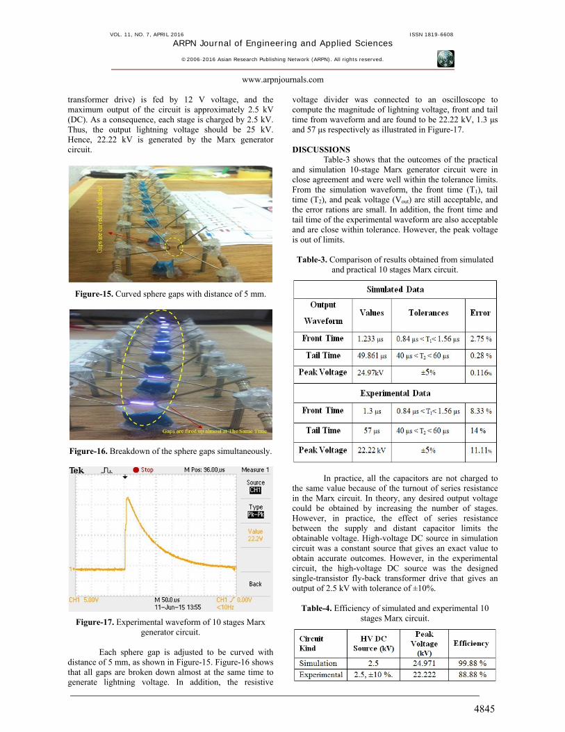
transformer drive) is fed by 12 V voltage, and the maximum output of the circuit is approximately 2.5 kV (DC). As a consequence, each stage is charged by 2.5 kV. Thus, the output lightning voltage should be 25 kV. Hence, 22.22 kV is generated by the Marx generator circuit.
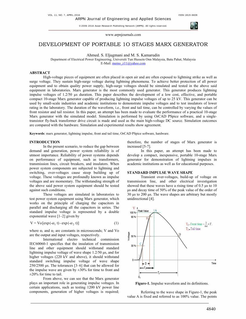
Figure-15. Curved sphere gaps with distance of 5 mm.
Figure-16. Breakdown of the sphere gaps simultaneously.
Figure-17. Experimental waveform of 10 stages Marx generator circuit.
Each sphere gap is adjusted to be curved with
distance of 5 mm, as shown in Figure-15. Figure-16 shows that all gaps are broken down almost at the same time to generate lightning voltage. In addition, the resistive
voltage divider was connected to an oscilloscope to compute the magnitude of lightning voltage, front and tail time from waveform and are found to be 22.22 kV, 1.3 μs and 57 μs respectively as illustrated in Figure-17.
DISCUSSIONS
Table-3 shows that the outcomes of the practical and simulation 10-stage Marx generator circuit were in close agreement and were well within the tolerance limits. From the simulation waveform, the front time (T1), tail time (T2), and peak voltage (Vout) are still acceptable, and the error rations are small. In addition, the front time and tail time of the experimental waveform are also acceptable and are close within tolerance. However, the peak voltage is out of limits.
Table-3. Comparison of results obtained from simulated and practical 10 stages Marx circuit.
In practice, all the capacitors are not charged to the same value because of the turnout of series resistance in the Marx circuit. In theory, any desired output voltage could be obtained by increasing the number of stages. However, in practice, the effect of series resistance between the supply and distant capacitor limits the obtainable voltage. High-voltage DC source in simulation circuit was a constant source that gives an exact value to obtain accurate outcomes. However, in the experimental circuit, the high-voltage DC source was the designed single-transistor fly-back transformer drive that gives an output of 2.5 kV with tolerance of ±10%.
Table-4. Efficiency of simulated and experimental 10
stages Marx circuit.

VOL. 11, NO. 7, APRIL 2016 ISSN 1819-6608
ARPN Journal of Engineering and Applied Sciences
©2006-2016 Asian Research Publishing Network (ARPN). All rights reserved.
www.arpnjournals.com
4846
The efficiency of the experimental and simulated
10-stage Marx generator circuit is estimated and shown in Table-4.
CONCLUSIONS
In this paper, the applicability of an inexpensive and compact 10-stage Marx generator circuit for demonstrating lightning impulse voltage waveforms and testing low-rating power system equipment has been debated. This inexpensive compact Marx generator circuit has been simulated by PSpice software environment and was tested in the laboratory. The experimental circuit was fired up by high-voltage DC generated by the single-transistor fly-back transformer drive circuit.
The waveforms are controlled by changing the stage front resistor and tail resistor. Front time is controlled by changing the stage front resistor, and tail time is controlled by changing the tail resistor. The tolerances that are allowed in the front and tail times are respectively ±30% and ±20%. The ratio of capacitance of charging and discharging capacitors is taken as 40.
This Marx generator circuit can generate peak impulse voltage of 25 kV. Given the inconsistency of high-rating DC voltage source and some loses that have been discussed, about 22.22 kV voltage could be generated. The experimental results were compared with simulation results, which were extremely desired and were in close agreement to standard impulse generator 1.2/50μs wave shape.
The simulation circuit used in this work could be utilized to predetermine the front time, tail time, and peak voltage of lightning impulse waves at any desired test voltage. The outcomes could be compared with the developed model. This approach would economize cost and time. REFERENCES [1] Elfsberg M., Hurtig T., Larsson A., Möller C. and
Nyholm S. E. 2008. Experimental studies of anode and cathode materials in a repetitive driven axial vircator. IEEE Trans. Plasma Science. 36(3): 688-693.
[2] Kuffel E., Zaengl W. S. and Kuffel J. 2000. High voltage Engineering fundamentals. Fundamentals of machine and machine tools. 2nd Ed. Newness Publications. pp. 115-119.
[3] Swaffield D. J., Lewin P. L., Dao N. L. and Hallstrom J. K. 2007. Lightning impulse wave-shapes: defining the true origin and its impact on parameter evaluation. University of Southampton, Southampton, Hampshire, SO17 1BJ, UK, 2.
[4] Moses G. L. 1965. Impulse Levels of Large High-Voltage Generators. IEEE Trans. Power Apparatus and Systems. 11(84): 1007-1011.
[5] Suthar J. L., Laghari J. R. and Saluzzo T. J. 1991. Usefulness of SPICE in high voltage engineering. IEEE Trans. Power Systems. 6(3): 1272-1278.
[6] Sakamoto T. and Akiyama H. 2013. Solid-State Dual Marx Generator with a Short Pulsewidth. IEEE Trans. Plasma Science. 41(10): 2649-2653.
[7] J. Hammon, S. K. Lam D. Drury and M. Ingram. 1997. Compact 1MV, 10 Hz Pulser. 11th IEEE Int. Pulsed Power Conference. pp. 147-152.


![1 L 25 Electricity & Magnetism [2] static electricity static electricity –the charging process –the van de Graff generator –electrostatic shielding lightning.](https://static.fdocuments.in/doc/165x107/56649e215503460f94b0e47f/1-l-25-electricity-magnetism-2-static-electricity-static-electricity-the.jpg)


