A Scalar Resonant-Filter-Bank-Based Output-Voltage Control ...

DEVELOPMENT OF P-RESONANT VOLTAGE CONTROL FOR DC MOTOR
USING ARDUINO
ABDUL HADI BIN ABDULLAH
A project report submitted in partial
fulfillment of the requirement for the award of the
Master of Electrical Engineering
Faculty of Electrical and Electronic Engineering
Universiti Tun Hussein Onn Malaysia
JULY 2014

v
ABSTRACT
This project described about to design and to development of P-Resonant voltage
control for DC motor. The objective of P-Resonant controllers is applied to control
the output voltage of the DC motor. An Arduino board device is used as a medium
for the implementation of the control system design. The P-Resonant controller is
developed and simulates using MATLAB/Simulink software. MATLAB block
diagram is downloaded into Arduino which will generate the PWM signal. The
signal is transmitted from the gate driver to the three phase rectifier to produce a
direct current voltage for the motor. The voltage produced is in accordance with the
specified value at the reference voltage. The actual voltage will try to reference
voltage with the comparison method and control of the ' P-Resonant '. The difference
is then corrected to minimize the voltage error. A simple hardware implementation
of the PR voltage controller is designed and the experimental results are presented to
demonstrate the validity of this approach. The results are observed in two main part;
simulation and hardware. Each part has an open loop control and close loop control.
It has been observed that the designed system has been successfully implemented.
vi
ABSTRAK
Projek ini menerangkan tentang reka bentuk dan pembangunan kawalan ‘P-
Resonant’ voltan bagi motor arus terus. Objektif pengawalan ‘P-Resonant’
digunakan untuk mengawal voltan keluaran Motor arus terus. Arduino digunakan
sebagai perantaraan untuk melaksanakan reka bentuk sistem kawalan. Pengawal ‘P-
Resonant’ dibangunkan dan disimulasi menggunakan perisian MATLAB/Simulink.
Rajah blok MATLAB dimuat-turun ke dalam Arduino yang akan menjanakan isyarat
PWM. Isyarat dihantar daripada pemandu pintu kepada penerus tiga fasa untuk
menghasilkan voltan berbentuk arus terus kepada motor DC. Voltan yang dihasilkan
adalah mengikut nilai yang ditetapkan pada voltan rujukan. Voltan sebenar akan
cuba mengikut voltan rujukan dengan kaedah perbandingan dan kawalan daripada
‘P-Resonant’. Perbezaan kemudian diperbetulkan dengan itu meminimumkan ralat
voltan. Perkakasan mudah pelaksanaan pengawal voltan ‘PR’ adalah direka dan
keputusan eksperimen dibentangkan untuk menunjukkan kesahihan pendekatan ini.
Keputusan dipatuhi dalam dua bahagian utama; Simulasi dan perkakasan. Setiap
bahagian mempunyai kawalan gelung terbuka dan kawalan gelung rapat. Ianya telah
diuji dan sistem yang direka telah berjaya dilaksanakan

vii
CONTENTS
TITLE i
DECLARATION ii
DEDICATION iii
ACKNOWLEDGEMENT iv
ABSTRACT v
ABSTRAK vi
CONTENTS vii
LIST OF TABLES ix
LIST OF FIGURES x
LIST OF SYMBOLS AND ABRREVIATIONS xii
LIST OF APPENDICES xiii
CHAPTER 1 INTRODUCTION 1
1.1 Background 1
1.2 Problem statement 3
1.3 Objective 4
1.4 Scope 5
CHAPTER 2 LITERATURE REVIEW 6
2.1 Dc motor 6
2.2 MATLAB 9
2.3 Arduino 10
2.4 Control Method 10
2.4.1 PID controller 11
2.4.2 Fuzzy logic controller 11
2.4.3 Repetitive controller 13
2.4.4 Proportional-resonant controller 13
2.5 Gate Driver 15
viii
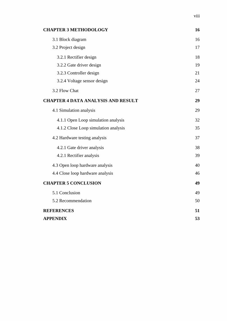
CHAPTER 3 METHODOLOGY 16
3.1 Block diagram 16
3.2 Project design 17
3.2.1 Rectifier design 18
3.2.2 Gate driver design 19
3.2.3 Controller design 21
3.2.4 Voltage sensor design 24
3.2 Flow Chat 27
CHAPTER 4 DATA ANALYSIS AND RESULT 29
4.1 Simulation analysis 29
4.1.1 Open Loop simulation analysis 32
4.1.2 Close Loop simulation analysis 35
4.2 Hardware testing analysis 37
4.2.1 Gate driver analysis 38
4.2.1 Rectifier analysis 39
4.3 Open loop hardware analysis 40
4.4 Close loop hardware analysis 46
CHAPTER 5 CONCLUSION 49
5.1 Conclusion 49
5.2 Recommendation 50
REFERENCES 51
APPENDIX 53

ix
LIST OF TABLES
4.1 Comparison between target and actual voltage for open loop simulation 34
4.2 Comparison between target and actual voltage for open loop simulation 37
4.3 Data for open loop hardware analysis 45
x
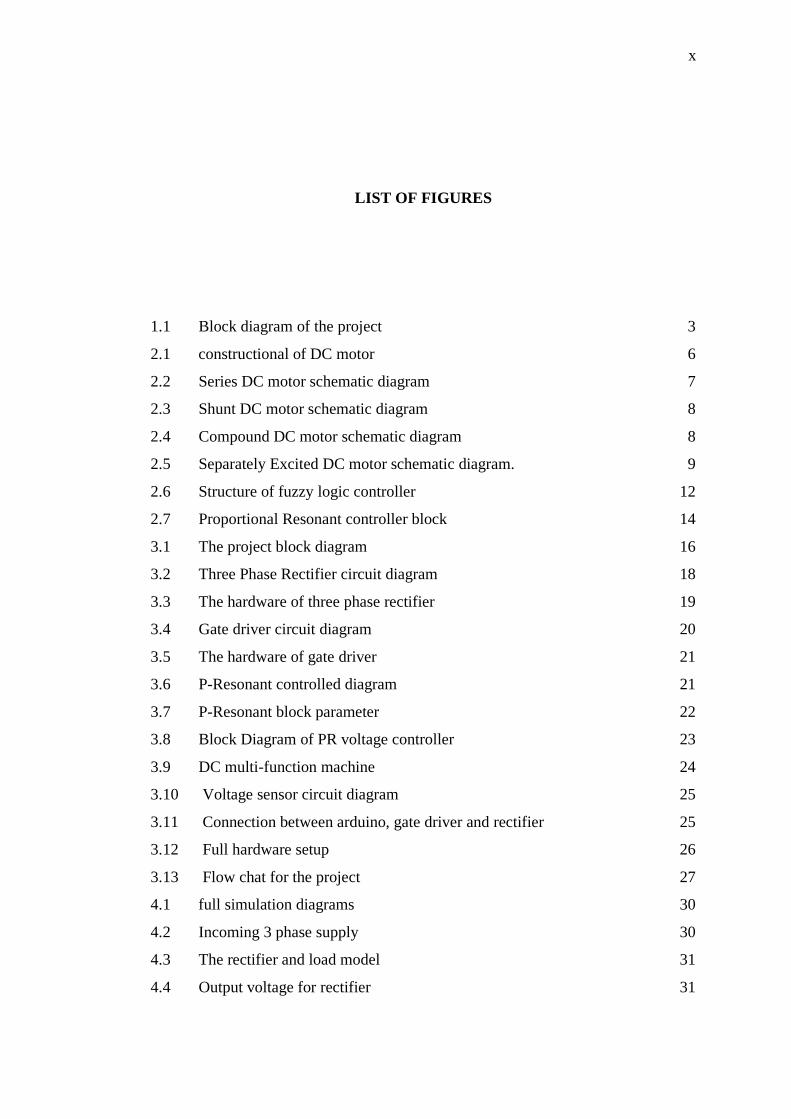
LIST OF FIGURES
1.1 Block diagram of the project 3
2.1 constructional of DC motor 6
2.2 Series DC motor schematic diagram 7
2.3 Shunt DC motor schematic diagram 8
2.4 Compound DC motor schematic diagram 8
2.5 Separately Excited DC motor schematic diagram. 9
2.6 Structure of fuzzy logic controller 12
2.7 Proportional Resonant controller block 14
3.1 The project block diagram 16
3.2 Three Phase Rectifier circuit diagram 18
3.3 The hardware of three phase rectifier 19
3.4 Gate driver circuit diagram 20
3.5 The hardware of gate driver 21
3.6 P-Resonant controlled diagram 21
3.7 P-Resonant block parameter 22
3.8 Block Diagram of PR voltage controller 23
3.9 DC multi-function machine 24
3.10 Voltage sensor circuit diagram 25
3.11 Connection between arduino, gate driver and rectifier 25
3.12 Full hardware setup 26
3.13 Flow chat for the project 27
4.1 full simulation diagrams 30
4.2 Incoming 3 phase supply 30
4.3 The rectifier and load model 31
4.4 Output voltage for rectifier 31

xi
4.5 Open loop simulation models 32
4.6 Actual voltage with vref = 30V 32
4.7 Actual voltage with vref = 35V 33
4.8 Actual voltage with vref = 40V 34
4.9 Close loop simulation model 35
4.10 Actual voltage with vref = 30V 36
4.11 Actual voltage with vref = 35V 36
4.12 Actual voltage with vref = 40V 37
4.13 The output signal from Arduino and gate driver 38
4.14 The output signal of gate driver circuit 39
4.15 Uncontrolled output voltage of rectifier 39
4.16 The open loop model 40
4.17 PWM output from Arduino for voltage constant, V=1V 41
4.18 PWM output from Arduino for voltage constant, V=3V 41
4.19 PWM output from Arduino for voltage constant, V=5V 42
4.20 Output from Arduino and gate driver for voltage constant, V=1V 42
4.21 Output from Arduino and gate driver for voltage constant, V=3V 43
4.22 Output from Arduino and gate driver for voltage constant, V=5V 43
4.23 Output voltage for voltage constant, V=1V 44
4.24 Output voltage for voltage constant, V=3V 44
4.25 Output voltage for voltage constant, V=5V 45
4.26 The close loop model 46
4.27 PWM output waveform from gate driver 47
4.28 DC output waveform for Vref = 30Vdc 47
4.29 DC output waveform for Vref = 35Vdc 48
4.30 DC output waveform for Vref = 40Vdc 48
xii
LIST OF SYMBOLS AND ABRREVIATIONS
AC
- Alternating Current;
DC - Direct Current;
PID - Proportional Integral Derivative;
IM - Induction Motor;
PWM - Pulse Width Modulation;
PR - Proportional Resonant;
FLC - Fuzzy Logic Controller

xiii
LIST OF APPENDICES
APPENDIX TITLE PAGE
A Layout of gate driver and rectifier 53
B Data sheet of MOSFET IRF840 54
C Data sheet of DC-DC converter IL0515S 56
D Data sheet of Optocoupler 57

CHAPTER 1
INTRODUCTION
1.1 Background
The direct current (DC) motor is a device that used in many industries in order to
convert electrical energy into mechanical energy. There are several kinds of DC
motors; examples are stepper motors, servos, brushed/brush-less motors. These all
results from the availability of speed controllers is wide range, easily and many
ways. In most applications, speed control is very important [1]. Speed of dc motor is
controlled by increasing or decreasing the voltage or current. This will affect the
speed of the dc motor. So, it is important to make a controller to control the speed of
DC motor in desired speed.
A rectifier is an electrical device that converts alternating current (AC),
which periodically reverses direction, to direct current (DC), which flows in only one
direction. The process is known as rectification. Rectifiers have many uses, but are
often found serving as components of DC power supplies and high-voltage direct
current power transmission systems. Rectification may serve in roles other than to
generate direct current for use as a source of power. As noted, detectors of radio
signals serve as rectifiers. In gas heating systems flame rectification is used to detect
presence of flame [2].
There are different types of controller that can be used to control the speed of
a dc motor, for example PI, PID, Fuzzy Logic, Repetitive, Time Delay and PR. The
recently introduced proportional-resonant (PR) controllers and their suitability for
2
current or voltage control of grid-connected converters. Using the PR controllers, the
converter reference tracking performance can be enhanced and previously known
shortcomings associated with conventional PI controllers can be alleviated. These
shortcomings include steady-state errors in single-phase systems in three-phase
systems. PR control theory is revised in detail with a number of practical cases that
have been implemented previously, described clearly to give a comprehensive
reference on PR control [3].
Arduino is a tool for making computers that can sense and control more of
the physical world than your desktop computer. It's an open-source physical
computing platform based on a simple microcontroller board, and a development
environment for writing software for the board. Arduino can be used to develop
interactive objects, taking inputs from a variety of switches or sensors, and
controlling a variety of lights, motors, and other physical outputs. Arduino projects
can be stand-alone, or they can be communicating with software running on your
computer such as MATLAB. The boards can be assembled by hand or purchased
preassembled.
MATLAB is a high-performance language for technical computing. It
integrates computation, visualization, and programming environment. Furthermore,
MATLAB is a modern programming language environment: it has sophisticated data
structures, contains built-in editing and debugging tools, and supports object-
oriented programming. These factors make MATLAB an excellent tool for teaching
and research [4].
3
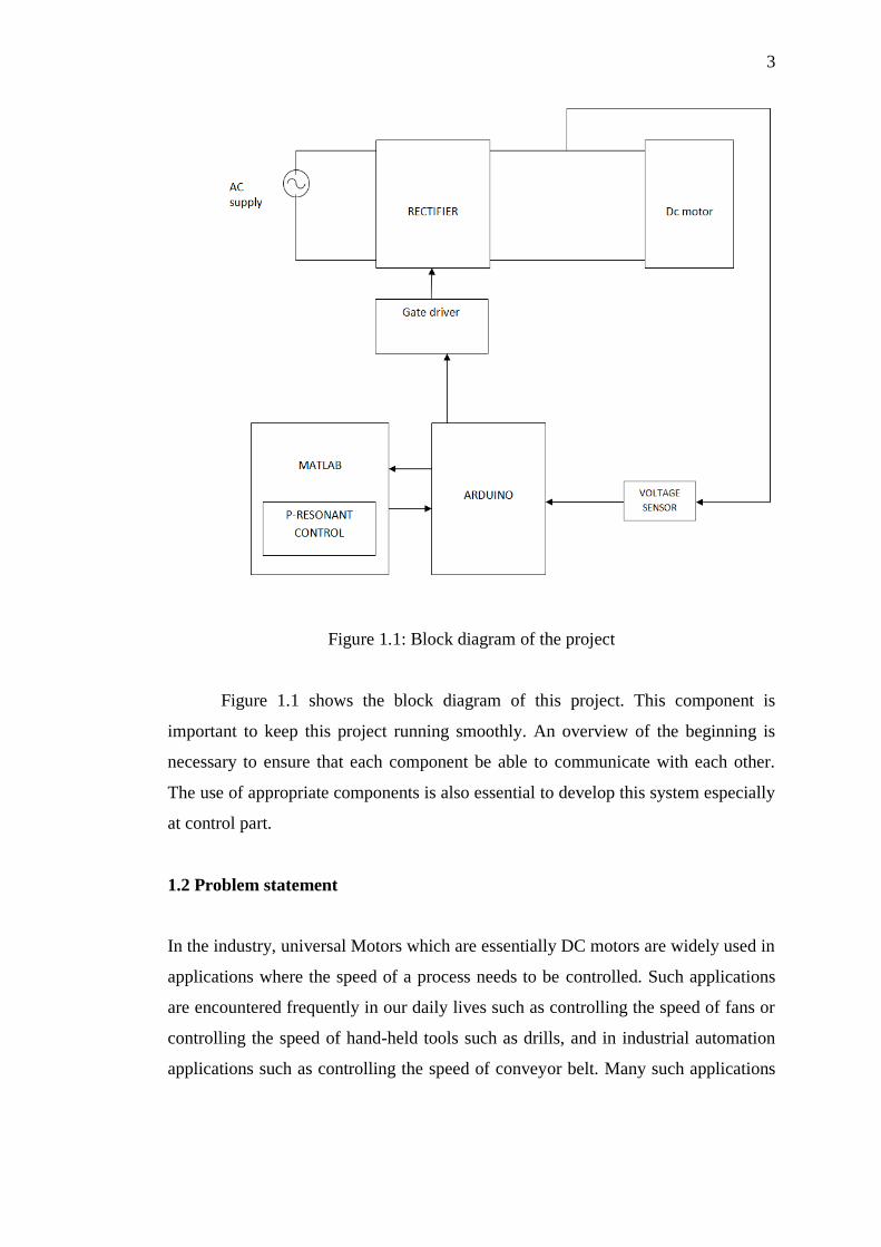
Figure 1.1: Block diagram of the project
Figure 1.1 shows the block diagram of this project. This component is
important to keep this project running smoothly. An overview of the beginning is
necessary to ensure that each component be able to communicate with each other.
The use of appropriate components is also essential to develop this system especially
at control part.
1.2 Problem statement
In the industry, universal Motors which are essentially DC motors are widely used in
applications where the speed of a process needs to be controlled. Such applications
are encountered frequently in our daily lives such as controlling the speed of fans or
controlling the speed of hand-held tools such as drills, and in industrial automation
applications such as controlling the speed of conveyor belt. Many such applications

4
which utilize DC motors have requirements associated with the steady-state speed
and/or a ramp up time for the motor to reach this speed.
Some of the most common problems with the dc motors include its inefficiency
to start immediately. There are many reasons for its incapability to start such as low
voltage supply, wrong connection, excessive load, frozen bearing, ground fault and
so forth. Sparks in the brushes is another problem associated with the dc motors.
Sparks may be caused due to insufficient contact and inappropriate size of the
brushes.
The most issue discusses in speed controller is regarding their efficiency and
reliability. The efficiency element is important in order to save cost. The efficiency
of speed controller is depending on method control system. The speed controller
usually control in analog system.
Manual controller is also not practical in the new technology era because it
wasting time and cost. Operation cost regarding controller is got attention from
industrial field. In order to reduce cost and time, we suggest making a controller
based on computer because it is portable. The user can monitor their system at
certain place without need to going the plant (machine) especially in industrial
implementation. From that, the man power can be reduced and reserve with
computer which is more precise and reliable.
1.3 Objective
Basically, this project is listing four main objectives. The objectives are a guideline
and goal in order to complete this project. This project is conducted to achieve the
following objectives:
To integrate communication between MATLAB and Arduino software.
To develop a proportional resonant (P-Resonant) voltage controller for DC
motor control.
To design gate driver for converter circuit.
To design the three phase rectifier circuit for dc motor.
5
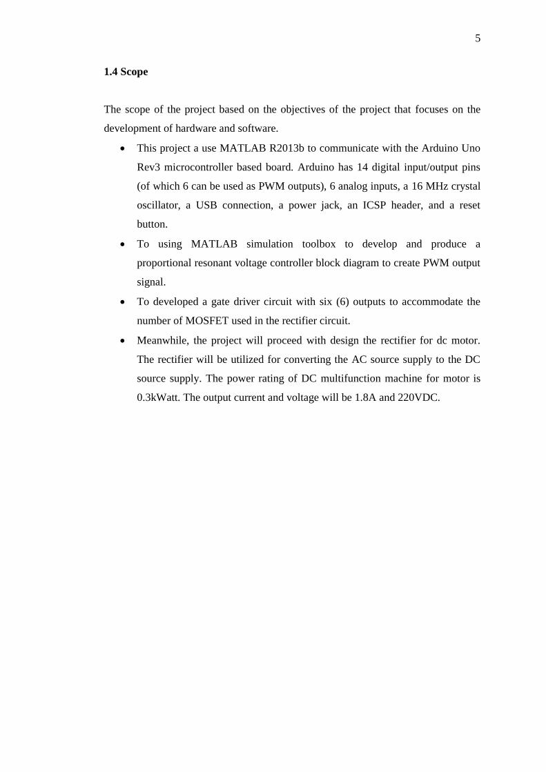
1.4 Scope
The scope of the project based on the objectives of the project that focuses on the
development of hardware and software.
This project a use MATLAB R2013b to communicate with the Arduino Uno
Rev3 microcontroller based board. Arduino has 14 digital input/output pins
(of which 6 can be used as PWM outputs), 6 analog inputs, a 16 MHz crystal
oscillator, a USB connection, a power jack, an ICSP header, and a reset
button.
To using MATLAB simulation toolbox to develop and produce a
proportional resonant voltage controller block diagram to create PWM output
signal.
To developed a gate driver circuit with six (6) outputs to accommodate the
number of MOSFET used in the rectifier circuit.
Meanwhile, the project will proceed with design the rectifier for dc motor.
The rectifier will be utilized for converting the AC source supply to the DC
source supply. The power rating of DC multifunction machine for motor is
0.3kWatt. The output current and voltage will be 1.8A and 220VDC.

CHAPTER 2
LITERATURE REVIEW
2.1 Dc motor
A DC Motor in simple words is a device that converts direct current
(electrical energy) into mechanical energy. It’s of vital importance for the industry
today, and is equally important for engineers to look into the working principle of
DC motor. In order to understand the operating principle of dc motor we need to first
look into its constructional feature in figure 2.1 [5].
Figure 2.1: constructional of DC motor
DC motor is considered a system having torque/speed characteristics
compatible with most mechanical loads. This makes a DC motor controllable over a
wide range of speeds by proper adjustment of the terminal voltage. Now days

7
induction motors, Brushless DC motors and Synchronous motors have gained
widespread use in electric traction system. Hence dc motors are always a good
option for advanced control algorithm because the theory of dc motor speed
control is known more than other types. Speed control techniques in separately
excited dc motor by varying the armature voltage for below rated speed [6].
A series dc motor gets its name from the fact that the field winding in this
case is connected internally in series to the armature winding such as figure 2.2.
Thus the field windings are exposed to the entire armature current unlike in the case
of a shunt motor. A dc series motor is usually built for fractional. Horse power sizes.
It is normally used to drive portable apparatuses. Series dc motors are extensively
used in many applications that require high starting torque such as cranes, hoists,
electric traction, etc [7].
Figure 2.2: Series DC motor schematic diagram
A shunt DC motor connects the armature and field windings in parallel or
shunt with a common DC power source in Figure 2.3. This type of motor has good
speed regulation even as the load varies, but does not have the starting torque of a
series DC motor. It is typically used for industrial, adjustable speed applications,
such as machine tools, winding/unwinding machines and tensioners [8].

8
Figure 2.3: Shunt DC motor schematic diagram
A compound DC motor connects the armature and fields windings in a shunt
and a series combination to give it characteristics of both a shunt and a series DC
motor. This motor is used when both a high starting torque and good speed
regulation is needed. The motor can be connected in two arrangements: cumulatively
or differentially. Cumulative compound motors connect the series field to aid the
shunt field, which provides higher starting torque but less speed regulation. In figure
2.4, differential compound DC motors have good speed regulation and are typically
operated at constant speed. In a compound motor the magnetizing flux consists in
two parts, one depending on the parallel or shunt current and one function of the
armature current that flows through the coils in series of the motor armature [9].
Figure 2.4: Compound DC motor schematic diagram
As the name suggests, in case of a separately excited DC Motor the supply is
given separately to the field and armature windings. The main distinguishing fact in
these types of dc motor is that, the armature current does not flow through the field

9
windings, as the field winding is energized from a separate external source of dc
current as shown in the Figure 2.5.
Figure 2.5: Separately Excited DC motor schematic diagram.
2.2 MATLAB
The name MATLAB stands for Matrix Laboratory. MATLAB was written originally
to provide easy access to matrix software developed by the LINPACK (linear system
package)and EISPACK (Eigen system package) projects. MATLAB is a high-
performance language for technical computing. It integrates computation,
visualization, and programming environment. Furthermore, MATLAB is a modern
programming language environment: it has sophisticated data structures, contains
built-in editing and debugging tools, and supports object-oriented programming.
These factors make MATLAB an excellent tool for teaching and research [4].
MATLAB has many advantages compared to conventional computer
languages for solving technical problems. MATLAB is an interactive system whose
basic data element is an array that does not require dimensioning. The software
package has been commercially available since 1984 and is now considered as a
standard tool at most universities and industries worldwide. It has powerful built-in
routines that enable a very wide variety of computations. It also has easy to use
graphics commands that make the visualization of results immediately available.
Specific applications are collected in packages referred to as toolbox. There are
toolboxes for signal processing, symbolic computation, control theory, simulation,
optimization, and several other fields of applied science and engineering.

10
2.3 Arduino
The Arduino Uno is a microcontroller board based on the ATmega328 (datasheet). It
has 14 digital input/output pins (of which 6 can be used as PWM outputs), 6 analog
inputs, a 16 MHz ceramic resonator, a USB connection, a power jack, an ICSP
header, and a reset button. It contains everything needed to support the
microcontroller; simply connect it to a computer with a USB cable or power it with a
AC-to-DC adapter or battery to get started. The Uno differs from all preceding
boards in that it does not use the FTDI USB-to-serial driver chip. Instead, it features
the Atmega16U2 (Atmega8U2 up to version R2) programmed as a USB-to-serial
converter [10].
Arduino can sense the environment by receiving input from a variety of
sensors and can affect its surroundings by controlling lights, motors, and other
actuators. The microcontroller on the board is programmed using the Arduino
programming language (based on Wiring) and the Arduino development
environment (based on Processing). Arduino projects can be stand-alone or they can
communicate with software running on a computer (e.g. Flash, Processing,
MaxMSP) [11].
Arduino is composed of two major parts: the Arduino board, which is the
piece of hardware you work on when you build your objects; and the Arduino IDE,
the piece of software you run on your computer. You use the IDE to create a sketch
(a little computer program) that you upload to the Arduino board. The sketch tells the
board what to do [12].
2.4 Control Method
Many controllers have been developed, that can be divided into two classifications,
passive and adaptive power controller. The example for passive power controller
relay and sliding mode control and for adaptive power controller is PID, fuzzy,
Repetitive and P-resonant controller. Each of them has their advantages, such as
simple structure and low maintenance cost.

11
2.4.1 PID controller
The Proportional(P)+Integral(I)+Derivative(D), i.e. PID control algorithm is most
widely used in industrial applications. We have implemented a PID controller to
control the motor speed. The error between the reference speed and the actual speed
is given as input to a PID controller. The PID controller depending on the error
changes its output, to control the plant input such that the error is minimized [13].
(2.1)
The proportional control (Kp) is used so that the control signal u(t) responds
to the error immediately. But the error is never reduced to zero and an offset error is
inherently present. To remove the offset error the Integral control action (TI) is used.
To Derivative control (TD) is used to dampen out oscillations in the plant response.
Also, the presence of derivative control reduces the need of Kp being large to
achieve stability. PID controller was implemented and the performance of the system
was evaluated. The control algorithms were implemented using OP-AMPs. The
details of implementation are given in the following sections. Proportional-Integral
Derivative (PID) controllers have been widely used for speed and position control of
DC motor [14]. A PID (proportional-integral-derivative) controller is one of the most
commonly used controllers because it is simple and robust. Also, it is suitable for use
in a control system where the transfer function of the plant has not been completely
defined [15].
2.4.2 Fuzzy logic controller
A fuzzy logic model is a logical-mathematical procedure based on an “IF-THEN”
rule system that mimics the human way if thinking in computational form.
Generally, a fuzzy rule system has four modules [16].
Fuzzification
Fuzzy Inference
Rule base
Defuzzification
12
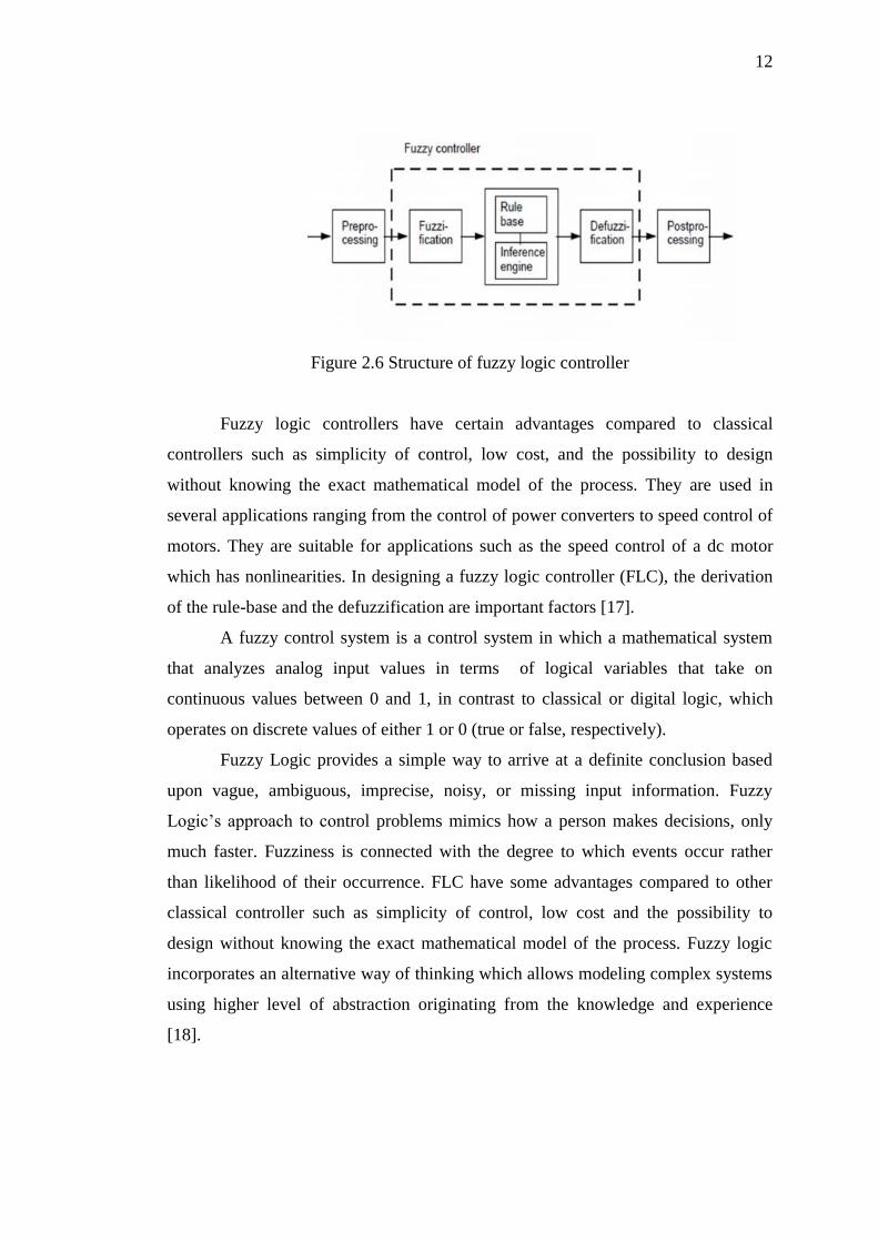
Figure 2.6 Structure of fuzzy logic controller
Fuzzy logic controllers have certain advantages compared to classical
controllers such as simplicity of control, low cost, and the possibility to design
without knowing the exact mathematical model of the process. They are used in
several applications ranging from the control of power converters to speed control of
motors. They are suitable for applications such as the speed control of a dc motor
which has nonlinearities. In designing a fuzzy logic controller (FLC), the derivation
of the rule-base and the defuzzification are important factors [17].
A fuzzy control system is a control system in which a mathematical system
that analyzes analog input values in terms of logical variables that take on
continuous values between 0 and 1, in contrast to classical or digital logic, which
operates on discrete values of either 1 or 0 (true or false, respectively).
Fuzzy Logic provides a simple way to arrive at a definite conclusion based
upon vague, ambiguous, imprecise, noisy, or missing input information. Fuzzy
Logic’s approach to control problems mimics how a person makes decisions, only
much faster. Fuzziness is connected with the degree to which events occur rather
than likelihood of their occurrence. FLC have some advantages compared to other
classical controller such as simplicity of control, low cost and the possibility to
design without knowing the exact mathematical model of the process. Fuzzy logic
incorporates an alternative way of thinking which allows modeling complex systems
using higher level of abstraction originating from the knowledge and experience
[18].

13
2.4.3 Repetitive controller
Repetitive controller is a specialized control scheme for tracking periodic reference
commands and rejecting periodic disturbances with a known period. The advantage
of repetitive control is that the tracking error decreases with increasing number of
periodic motion. However, the positive feedback loop used to generate the periodic
signals which affect the stability of the system. In the end, the repetitive controller is
likely to make the system unstable. Therefore, the trade-off between stability and
tracking performance has been considered to be an important factor in the repetitive
control system [19].
2.4.4 Proportional-resonant controller
The proportional-resonant control is used in voltage control loop to achieve steady-
state accuracy and the ability to cancel the disturbances of load currents
simultaneously. The discrete domain control system analysis shows that the whole
system can obtain high quality steady-state compensation accuracy and fast dynamic
response [20].
PR controller has much in common with a common PI controller. The
difference consists only in the way the integration action takes part. The integrator
will only integrate frequencies very closed to the resonance frequency and will not
introduce stationary error or phase shift [21].
Proportional-resonant (PR) controller, which introduces an infinite gain at a
selected resonant frequency for eliminating steady state error, constituted by the
proportional regulator and resonant controller. The controller can be used to control
the DC signals, thus eliminating the need for coordinate system transformation, and
these advantages make it suitable for the power quality control applications with
high performance [20]. The PR controller GPR(s) is defined as:
(2.2)
Where: kp and kr are the controller coefficients, and ωo is considered as the
cut-off frequency.

14
The PR controller has been designed based on the frequency output of the IL.
As known the output is 50Hz. The aim of this controller is to control the sinusoidal
variable which has resonant frequency at 50Hz and in the same time reject others
frequencies. The PR controller is used where it has high gain at the resonant
frequency. Figure 2.7 shows the PR controller block. This controller needs to have
two controllers side which response to d and q components. The references values
for d and q are 1 and 0. At the end of this control process the d and q can be sum
together to generate the periodic signal that is used to generate the PWM signal to
the inverter [22].
Figure 2.7: Proportional Resonant controller block
Advantages of the PR controllers include the possibility of tuning their
individual resonant peaks to the grid frequency for precise fundamental reference
tracking and to some low-order harmonic frequencies for selective harmonic
compensation, and the possibility of implementing harmonic reference generator in
the stationary frame needed for active filters.
Implementation wise, the PR technique requires lesser computational
overhead and does not require an explicit grid voltage feed forward control path,
while still achieving the same performance as a synchronous PI controller. For three-
phase systems, the PR technique also has the unique feature of compensating for
both positive- and negative-sequence components simultaneously, unlike
synchronous PI where separate frame transformations are needed. Given these
advantages, PR controllers can certainly replace their PI counterparts [23].

15
2.5 Gate Driver
Gate drivers are electronic circuits that apply correct power levels to metal-oxide
field-effect transistors (MOSFETs) and insulated gate bipolar transistors (IGBTs).
With IGBTs, gate drivers serve as isolation amplifiers and often provide short-circuit
protection. Because of their insulated gates, IGBTs require a continuous gate circuit
in order to sustain gate current. Solid state switching technology has enhanced pulsed
power applications by extending capability in a mentioned area.
With power-MOSFETs, gate drivers can be implemented as transformers,
discrete transistors, or dedicated integrated circuits (IC). They can also be integrated
within controller ICs. Partitioning the gate-drive function of controllers that use
pulse width modulation (PWM) improves controller stability by eliminating the high
peak currents and heat dissipation needed to drive power-MOSFETs at very high
frequencies [24].
It’s specially designed to handle significant power levels. They’re only used
in “on” or “off” states, which has resulted in their being the most widely used low-
voltage switch. When compared to the IGBT, a power MOSFET has the advantages
of higher commutation speed and greater efficiency during operation at low voltages.
What’s more, it can sustain a high blocking voltage and maintain a high current. This
is because most power MOSFETs structures are vertical (not planar). Its voltage
rating is a direct function of the doping and thickness of the N-epitaxial layer, and its
current rating is related to the channel’s width (the wider the channel, the higher the
current). Due to its efficiency, power MOSFETs are used in power supplies, dc/dc
converters, and low-voltage motor controllers [25].
Driving power MOSFET at high switching frequency may induce significant
switching power losses. A gate driver with low energy consumption is proposed for
power MOSFET in switching power conversion applications. The proposed gate
driver regulates the output gate driving voltage for minimizing the loss of charging
and discharging the gate capacitor [26].
Among these technologies, semiconductors such as MOSFETs and IGBTs
have drawn attention in high frequency applications.
CHAPTER 3
METHODOLOGY
3.1 Block diagram
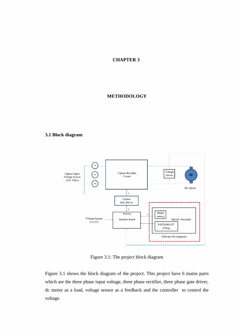
Figure 3.1: The project block diagram
Figure 3.1 shows the block diagram of the project. This project have 6 mains parts
which are the three phase input voltage, three phase rectifier, three phase gate driver,
dc motor as a load, voltage sensor as a feedback and the controller to control the
voltage.

17
The three phase input voltage applied to the source is from 0 to 40V with
frequency 50Hz. The second part is the rectifier. Rectifier will be used to convert
alternating current (AC) to direct current (DC) power supply. The system need
because the three phase dc motor as a load. The three phase rectifier also known as
the six switch rectifier type or full bridge rectifier and will receive the output PWM
from the gate driver.
For the third part, gate driver circuits are function to step up the signal PWM
from the arduino. The gate driver will step up the number and the amplitude of the
signal PWM to the three phase rectifier. The gate driver will produce six PWM
signal.
The DC motor was used as a load. The rating of the DC motor is 0.3kW,
220V, and 1.8A. DC multi-function machine for motor and generator operation, can
be used as shunt, series, separately excited, or compound wound machine, series and
shunt winding with tap for compounding, with commutating winding and
compensation winding. All windings are separately connected to 4 mm safety
sockets. When separately exited DC motor running, the sensor voltage will be
detected. Sensor voltages are used to send data to the Arduino. The output of the
voltage sensor will be used as a feedback to the controller.
The important part of the system is the controller. This project is to develop a
control voltage through P-resonant method for controlling the speed of a dc motor.
The controller will compare the motor voltage with the reference voltage and if there
is an error, the controller will generate the pulse width modulation to fed into the
three phase rectifier. By feeding the PWM to the rectifier, it will rescale the output to
power up the load. This process will continuous in the feedback until the error
approximately to zero.
3.2 Project design
To achieve the project, hardware designs have been made. In hardware development,
two main part which rectifier and their gate driver are the first to be design. Then the
other part is software for the controller design.

18
3.2.1 Rectifier design
In the three-phase rectifiers, MOSFETs are needed to produce power switching. In
this project, MOSFET IRF840 is used. For the six MOSFET, the circuit again has a
pulse number of six. For this reason, it is also commonly referred to as a six-pulse
bridge. Each gate of the MOSFET needs to give a signal to switching and finally 6
PWM must be built to give signal to the gate of MOSFET. Figure 3.2 shows the
circuit arrangement of three phase inverter in PROTEUS software.
Figure 3.2: Three Phase Rectifier circuit diagram

19
Figure 3.3: The hardware of three phase rectifier
Figure 3.3 shows the hardware of the three phase rectifier. At the right hand
side is the incoming with 23Vac supply from phase A, B and C in. The six positive
and negative (in front of MOSFET) is the PWM switching signal from gate driver.
While the left hand side is the Vdc input terminal block and connect to the dc motor.
3.2.2 Gate driver design
Figure 3.4 shows the gate driver for three phase rectifier. The function of the gate
driver is to produce 6 pulse PWM signal from three different phase inputs from
Arduino. In this project, the gate driver will step up the voltage from 5V to 15V by
voltage regulator IL0515S before sending it to the three phase rectifier.

20
Figure 3.4: Gate driver circuit diagram
The other main component in the gate driver is Gate Drive Optocoupler
HCPL3120. This optocoupler is ideally suited for driving power IGBT’s or
MOSFET’s used in motor control inverter application. The minimum supply voltage
of this optocoupler is 15V that are taken from the IL0515S which are the DC-DC
converter. The picture of the gate driver hardware is shown in Figure 3.5.

21
Figure 3.5: The hardware of gate driver
3.2.3 Controller design
Figure 3.6 shows the detail of P Resonant controller. The PR controller divides by a
grouping of proportional gain and integration gain. For the integration gain, ideal
controller transfer function is used.
Figure 3.6: P-Resonant controlled diagram

22
The value of 98696 is represents the sign of in Equation 2.2. It is based on
the calculation:
(3.1)
Figure 3.7: P-Resonant block parameter
The key component is the Arduino microcontroller. It is the control center of
the entire system. It contains all the software design for this project. The
microcontroller will receive signals from the voltage sensor. Then, the
microcontroller will send another signal to the motor based on the signal it receives.
After the motor receives the signal from the microcontroller, it will start rotate and
push a lever trigger.
The available data will be processed in MATLAB with P-Resonant
method.PR controller is used for controlling the voltage. Transfer function of a PR
controller is given by:
(3.2)
Where ω0, kp and ki are resonant frequency, proportional and integral gains of
controller, respectively. According to internal model principle, if the resonant

23
frequency of the PR controller is equal to the frequency of a sinusoidal reference
voltage, then the controller introducing an infinite gain at this frequency makes the
output voltage track the reference command. For achieving the control objectives
and modeling the rectifier and its PWM modulator as a constant gain, the control
voltage loop band-width is chosen much lower than the switching frequency of the
rectifier. Figure 3.8 shows the stationary PR block diagram for voltage controller.
Figure 3.8: Block Diagram of PR voltage controller
MATLAB simulation toolbox is using to develop and produce a proportional
resonant voltage controller block diagram to create PWM output signal. The
communication between MATLAB and Arduino will produce for controlling the
speed of a dc motor. Arduino will be sent data to a gate driver in Pulse Width
Modulator (PWM).
Then, Arduino will transmit data to gate driver. A gate driver' is a power
amplifier that accepts a low-power input from a voltage controller and produces a
high-current drive input for the gate of a high-power transistor that MOSFET. In
essence, a gate driver consists of a level shifter in control the switching.
This project will use DC multifunction machine as shown Figure 3.9. DC
multi-function machine for motor and generator operation, can be used as shunt,
series, separately excited, or compound wound machine, series and shunt winding
with tap for compounding, with commutating winding and compensation winding.
All windings are separately connected to 4 mm safety sockets.
The basic principle behind DC motor speed control is that the output speeds
of DC motor can be varied by controlling decreasing and increasing voltage to rated
speed keeping field voltage constant. The output speed is compared with the
reference speed and error signal is fed to speed controller. Controller output will vary

24
whenever there is a difference in the reference speed and the speed feedback. The
output of the speed controller is the control voltage that controls the operation duty
cycle. The converter output give voltage required to make the motor return to the
desired speed. The reference speed is provided through a potential divider because
the voltage from potential divider is linearly related to the speed of the DC motor.
Therefore, a dc motor can control by a modern computerized control system.
Figure 3.9: DC multi-function machine
3.2.4 Voltage sensor design
A voltage sensor (also known as a voltage divider) is a simple linear circuit that
produces an output voltage (Vout) that is a fraction of its input voltage (Vin).
Voltage division refers to the partitioning of a voltage among the components of the
divider. The formula governing a voltage divider is similar to that for a current
divider, but the ratio describing voltage division places the selected resistance in the
numerator.
In this project, a voltage sensor consists of two resistors in series or a
potentiometer. Voltage sensor should be set so as to be read by the Arduino and use
feedback as a reference voltage. Figure 3.10 shows the circuit diagram of voltage
sensor. Two resistors, 2500 ohm for R1 and 370 ohm for R2, was chosen so that the

51
REFERENCES
[1] P. W. Franklin and U. Missouri-Columbia, “theory of dc motor.” Power
Apparatus and Systems, IEEE Transactions on (Volume:PAS-91 , Issue: 1 ),
pp. 249 – 255, 1972.
[2] I. R. Visintini Elettra Synchrotron Light Laboratory, Trieste, “rectifiers.” pp.
133–183.
[3] R. Teodorescu, A. E. Sect. of Power Electron. &Drives, Aalborg Univ., and P.
C. Blaabjerg, F. ; Liserre, M. ; Loh, “proportional-resonant (PR) controllers.”
Electric Power Applications, IEE Proceedings (Volume:153 , Issue: 5 ), pp.
750 – 762, 2006.
[4] D. N. U. Houcque, INTRODUCTION TO MATLAB FOR ENGINEERING
STUDENTS, no. August. 2005.
[5] D. Type and P. Date, “DC Motor Theory,” pp. 1–2, 2006.
[6] J. S. Jaafer, “Speed control of separately excited DC motor using chopper,”
vol. 11, no. 1, pp. 26–35, 2013.
[7] D. C. Series, “SPEED CONTROL OF A : DC SERIES MOTOR USING
BUCK-,” no. 1, pp. 1–9.
[8] V. Singh, “Series Operation of a DC Shunt Motor,” vol. I, no. May, p. 1973,
1973.
[9] E. Soressi, “New life for old compound DC motors in industrial
applications?,” 2012 IEEE International Conference on Power Electronics,
Drives and Energy Systems (PEDES), pp. 1–6, Dec. 2012.
[10] A. Team, “Arduino Uno,” 2013. [Online]. Available:
http://scholar.google.com/scholar?hl=en&btnG=Search&q=intitle:Arduino+U
no#3. [Accessed: 09-Jul-2014].
[11] “What Is Arduino & What Can You Do With It? [Technology Explained].”
[Online]. Available: http://www.makeuseof.com/tag/arduino-technology-
explained/.
52
[12] M. Banzi and F. Edition, Getting started with arduino, First edit. O’Reillr
Media, Inc.
[13] N. A. Bhagat and M. B. Cep, “DC Motor Speed Control using PID
Controllers,” no. November, pp. 1–18, 2009.
[14] M. A. M. Hassan, “Speed Control of DC Motor Using PID Controller Based
on Artificial Intelligence Techniques,” pp. 196–201, 2013.
[15] P. I. Lin, S. Hwang, and J. Chou, “COMPARISON ON FUZZY LOGIC AND
PID CONTROLS FOR A DC MOTOR.”
[16] S. Wadhwani, “Speed Control of Separately Excited Dc,” vol. 4, no. June, pp.
2518–2523, 2013.
[17] S. Yuvarajan, “Fuzzy-Logic DC-Motor Controller With Improved,” pp. 1652–
1656, 1998.
[18] J. Ohri, “Speed Control of DC Motor using Fuzzy Logic based on,” vol. 3, no.
6, pp. 1–5, 2013.
[19] M. Vijayakarthick, S. Sathishbabu, and P. K. Bhaba, “Real time
implementation of Modified Repetitive Control Strategy in a DC motor,”
2010 11th International Conference on Control Automation Robotics &
Vision, pp. 109–113, Dec. 2010.
[20] K. Shen, J. Wang, Z. Gao, X. Cai, Y. Ji, and A. C. Topology, “Dynamic
Voltage Restorer Based on Proportional-resonant Control,” pp. 0–3, 2010.
[21] R. Teodorescu, F. Blaabjerg, A. East, and M. Liserre, “Proportional-Resonant
Controllers . A New Breed of Controllers Suitable for Grid-Connected
Voltage-Source Converters.”
[22] S. Inverters, S. Aizam, and Z. Zarafi, “Comparison Study in Various
Controllers in,” no. SCOReD, pp. 13–14, 2010.
[23] R. Teodorescu, F. Blaabjerg, M. Liserre, and P. C. Loh, “Proportional-
resonant controllers and filters for grid-connected voltage-source converters,”
vol. 153, no. 5, 2006.
[24] P. Iyengar, T. C. Lim, S. J. Finney, B. W. Williams, and G. Street, “Design
and Analysis of an Enhanced MOSFET Gate Driver for Pulsed Power
Applications,” pp. 1136–1145, 2013.
[25] P. M. Basics, “Application Note AN-1084.” .
[26] R. Tzeng, S. Member, C. Chen, and S. Member, “A Low-Consumption
Regulated Gate Driver for Power MOSFET,” vol. 24, no. 2, pp. 532–539,
2009.