Development of new power supplies for J-PARC MR upgrade Yoshi Kurimoto (KEK) for J-PARC accelerator...
14
Development of new power supplies for J-PARC MR upgrade Yoshi Kurimoto (KEK) for J-PARC accelerator group
-
Upload
sheena-montgomery -
Category
Documents
-
view
221 -
download
7
Transcript of Development of new power supplies for J-PARC MR upgrade Yoshi Kurimoto (KEK) for J-PARC accelerator...

Development of new power supplies for J-PARC MR upgrade
Yoshi Kurimoto (KEK)for J-PARC accelerator group

Contents
• About J-PARC Main Ring and Upgrade• Requirement for New Power Supply • Design of the New Power Supply• Capacitive Energy Storage • Development of the Capacitors • Next Step and Summary

J-PARC Main Ring (MR)
The current intensity is up to 250 kW (Fast Extraction)
Fast Extraction : Long baseline neutrino oscillation experiment (T2K) Slow Extraction : Hadron and Nuclear physics experiments
Proton beam is provided by 2 different extraction modes
Circumference 1568 m
Injection Energy 3 GeV
Extraction Energy 30 GeV
Repetition Rate 0.4 Hz
RF Frequency 1.67-1.72 MHz
Number of bunches 8
Synchrotron tune 0.0025-0.0001
Betatron tune 22.4, 20.75

Upgrade toward 750 kW OperationIncreasing Repetition Rate from 0.4 Hz to 1 Hz
Current PS New PS
Output Voltage 3 kV 6 kV
Output Current 1560 A 1560 A
Output Power 5 MW 10 MW
Rep. Period 2.5 s 1.0 s
Requirement for new Power Supply

Energy Storage
Output Power of the PS for one Bending magnet family
for all Bending Families
not allowed at main !!
Output Power Variation = 96 MVA
Current Power Supply
• Only one converter between load and main (current-type converter)
• No Energy Storage
Output Power = Power at main
Output Power Variation @ 1 Hz Operation
16 MVA
Need Energy Storage

Basic Design of new power supply
PS For Large Magnets ( B and Large Q ) PS For Small Magnets ( Small Q and Sext.)
• Large capacitive energy storage to reduce power variation at main grid • Choppers in series for higher output voltage (shorter ramp up time) • Low noise digital feedback system for precise current control
Design Concept for 1 Hz Operation

Effect of Capacitive Energy Storage
Input Power (Red)with capacitive energy storage
Input Power can be reduce by 70 %
Simulation for one bending magnet family
Magnetic Energy flow Loss Compensation
• All magnetic energy (~10 MJ for 1 bending family ) is provided from the capacitor energy storage
• Only loss is compensated from the main

Capacitive Energy Storage
1 s
have longer than 10 years lifetime ( ~ 108 charge-discharge cycles )not be shorted internally (for safety)
The capacitor should
Dry-type film Capacitor • Long lifetime• No internal short by self-healing structure • smaller and cheaper by recent technology
progress
Used for many applications such as shinkansen , hybird car and so on

Self-Healing Structure
• Many small pixel capacitors connect with each other• A pixel capacitor with weak part is isolated by over current• As a result, the capacitance decreases by 1/10000 • The lifetime is defined as the time until capacitance decreases by 5 %
Internal Structure of Film Capacitor
More pixels = Safer
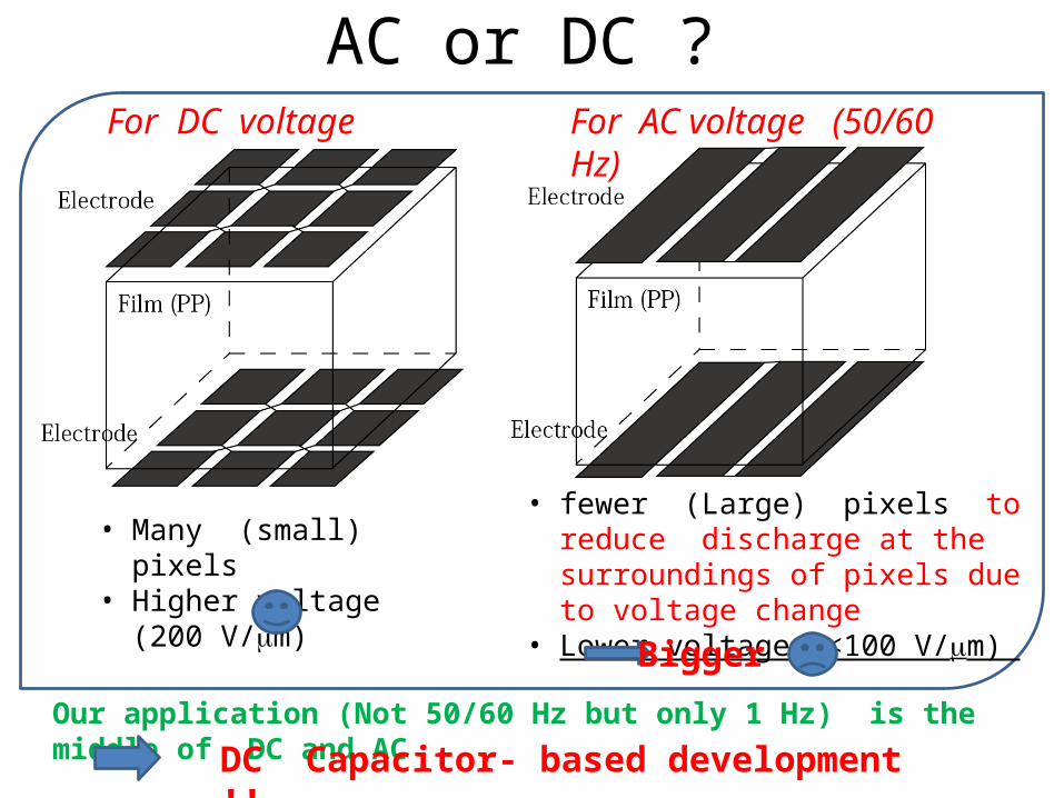
AC or DC ?For DC voltage For AC voltage (50/60 Hz)
• Many (small) pixels • Higher voltage (200
V/mm)
• fewer (Large) pixels to reduce discharge at the surroundings of pixels due to voltage change
• Lower voltage (<100 V/mm)
Bigger
Our application (Not 50/60 Hz but only 1 Hz) is the middle of DC and AC
DC Capacitor- based development !!

Lifetime test with DC capacitor
Material C is selected
Extrapolated lifetime (5 % capacitance drop) = 4.5 ×10⁸pulses
Difference of the electrode material 60 Hz (accelerating test by factor 60)
Capa
cita
nce
Dro
p (%
)
material Amaterial Bmaterial C
Capacitor design was fixed !!
Single capacitor : 2mF 2.5 kV 20-30 kg
Time (h)

Next Step
• number of capacitors in one unit bank ? • type of containers • selection of fuse • type of tests (short test with fuse ?)
We are currently working on those issue
Things to do for Capacitor bank design
Ex. PS Bending families (Most of capacitors are there )
2kV 100-200 mF50-100capacitors a few tons
×12 (# bending families)
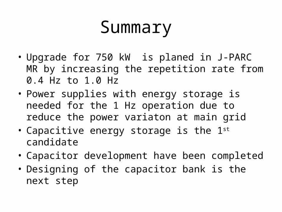
Summary
• Upgrade for 750 kW is planed in J-PARC MR by increasing the repetition rate from 0.4 Hz to 1.0 Hz
• Power supplies with energy storage is needed for the 1 Hz operation due to reduce the power variaton at main grid
• Capacitive energy storage is the 1st candidate • Capacitor development have been completed • Designing of the capacitor bank is the next step
10-6
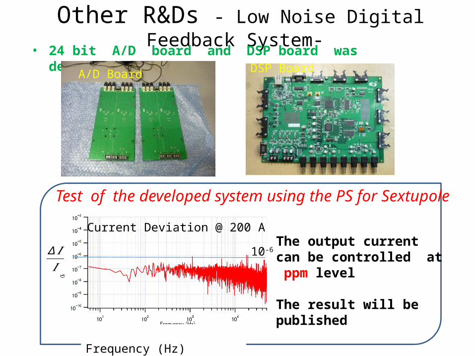
Other R&Ds - Low Noise Digital Feedback System-
∆ 𝐼𝐼
• 24 bit A/D board and DSP board was developed in KEK
Frequency (Hz)
Test of the developed system using the PS for Sextupole
Current Deviation @ 200 AThe output current can be controlled at ppm level
The result will be published
A/D Board DSP Board