
DEVELOPMENT OF NEUROFUZZY CONTROL SYSTEM FOR THE GUIDANCE OF AIR TO AIR MISSILES (Master Thesis)
70
م ي ح ر ل ا ن م ح ر ل له ا ل م ا س ب ما ” ل ع ى ن د ى ز ن ل ز ق “ و م ي$ عظ ل له ا ل ا صدق
-
Upload
ahmed-momtaz-hosny-phd -
Category
Career
-
view
303 -
download
3
Transcript of DEVELOPMENT OF NEUROFUZZY CONTROL SYSTEM FOR THE GUIDANCE OF AIR TO AIR MISSILES (Master Thesis)

الرحيم الرحمن الله بسم
علما ” زدنى ربى “ وقلالعظيم الله صدق

DEVELOPMENT OF NEUROFUZZY CONTROL SYSTEM FOR THE GUIDANCE OF AIR TO AIR MISSILES
byEng. Ahmed Momtaz Hosny
Under the Supervision of
Prof. Galal Hassan Professor of Systems Dynamics
Dr. Yasser ZeyadaAssistant Professor of Systems Dynamics
Mechanical Design and Production Department
AIM 9R MODEL DESCRIPTION
CONTROL STRATEGY
MAIN TOPICS
FINAL CONCLUSION
AIM 9 model
Cross Coupling effect
Gust Effect (system disturbance)
AIM 9R MODEL DESCRIPTION
HOME
Neural Network Controller
Fuzzy Logic Controller
Comparison between FLC and NNC
Low Pass Filter
Comparison between FLC and PDC
CONTROL STRATEGY
HOME

Hybrid System
Final Conclusion
HOME
FINAL CONCLUSION
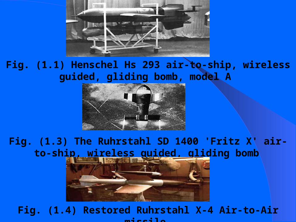
Fig. (1.1) Henschel Hs 293 air-to-ship, wireless guided, gliding bomb, model A
Fig. (1.3) The Ruhrstahl SD 1400 'Fritz X' air-to-ship, wireless guided, gliding bomb
Fig. (1.4) Restored Ruhrstahl X-4 Air-to-Air missile

Fig. (1.5) Types of ASM missiles

Fig. (1.6) Russian AAM

WARHEAD - 1000 LB. - W80 250 KILOTON THERMONUCLEAR OR 1000 LB. CONVENTIONAL HIGH EXPLOSIVE/FRAGMENTARYRANGE - 1,553 MILES WING SPAN - 100 INCHESLENGTH - 219 INCHES WEIGHT - 4,190 POUNDSENGINE - SOLID PROPELLENT BOOSTER/TURBOJET CRUISE one Williams F107-400 rated at 600 lbs. thrustGUIDANCE - TERCOM, GPS, DSMAC AND INFRA-REDSPEED - 550 MILES PER HOURCOST - $1.4 MILLION TO OVER $2 MILLION DEPENDING ON VERSION
Tomahawk
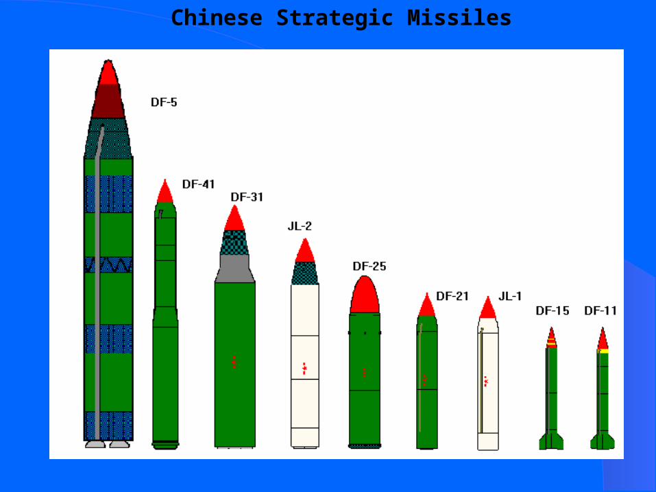
Chinese Strategic Missiles

DONG FENG 31 CAN STRIKE THREE TARGETS WITH NUCLEAR WARHEADS

DONG FENG 4 ICBM
3 MegaTon Warhead

Command guidance
GUIDANCE TYPES

Fig. (1.7) TERCOM, DSMAC missiles guidance technique

Fig. (1.11) Active homing system
Fig. (1.12) Semiactive homing system
Fig. (1.11b) Passive homing system

Fig. (1.13) Comparison between AIM 7 and AIM 120 guidance technique
GUIDANCE PHASES
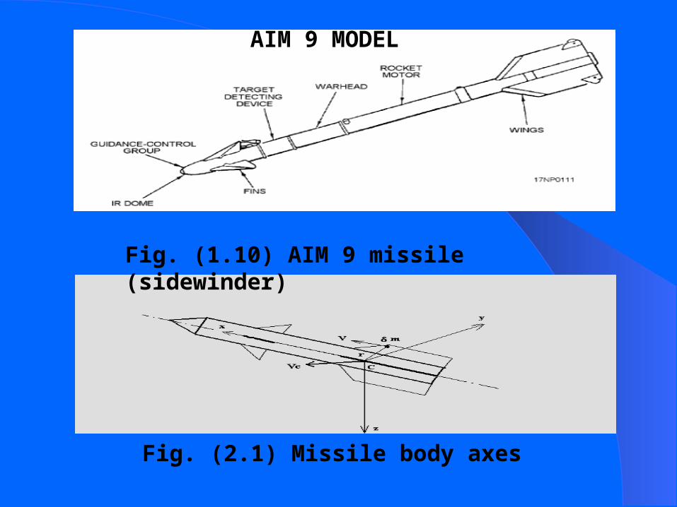
Fig. (2.1) Missile body axes
Fig. (1.10) AIM 9 missile (sidewinder)
AIM 9 MODEL


Fig. (2.4) AIM 9 model

Fig. A.3 Missile orientation

Fig. A.4 Flight path calculation

Fig. A.8 AIM 9 model (2-D)

Fig. (2.5) Pitch angle dynamic response for 3D and 2D models, linearization was performed at frequency =.2 (rad/s)

Fig. (2.6) Cross coupling effect (yaw * pitch)
Fig. (2.7) Mean value of cross coupling effect versus input frequencies at constant amplitude of .1(rad) rudder deflection
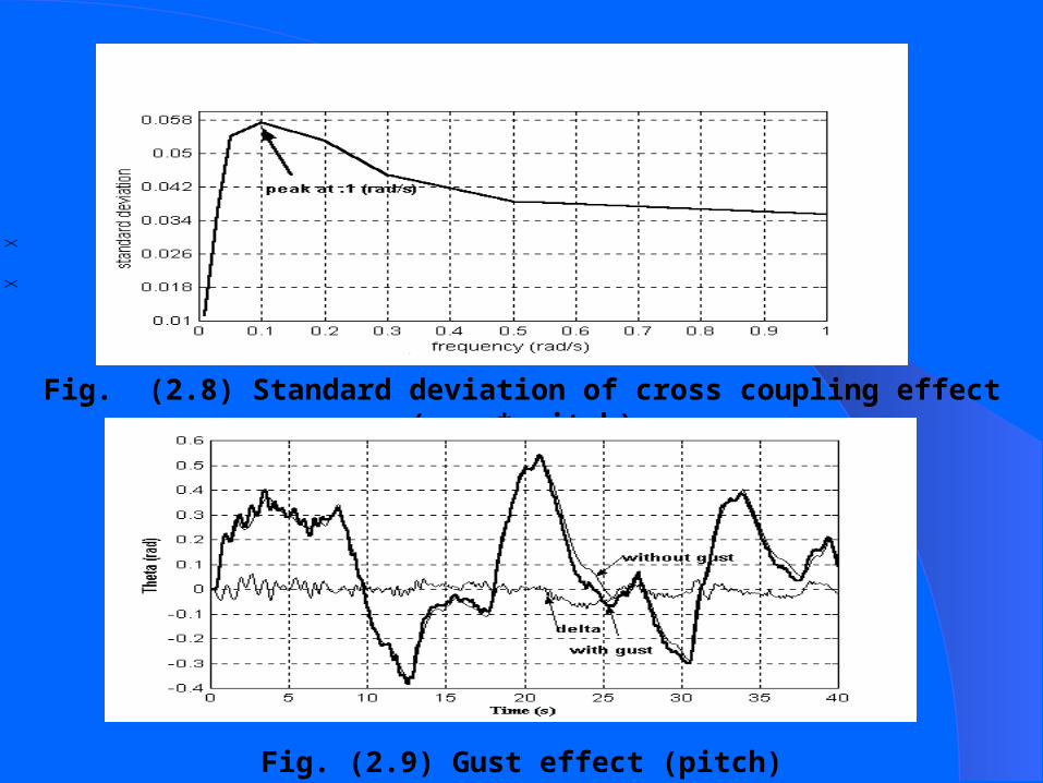
Fig. (2.8) Standard deviation of cross coupling effect (yaw * pitch)
Fig. (2.9) Gust effect (pitch)
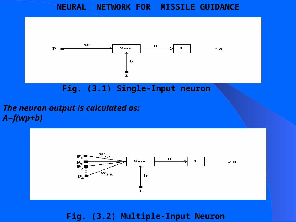
Fig. (3.1) Single-Input neuron The neuron output is calculated as:A=f(wp+b)
Fig. (3.2) Multiple-Input Neuron
NEURAL NETWORK FOR MISSILE GUIDANCE

Fig. (3.3) Layer of S Neurons
Fig. (3.4) Direct inverse control

Fig. (3.5) Control by Direct Inverse Control at steady state flight
Fig. (3.6) Control by Direct Inverse Control at climb angle =90 deg

Fig. (3.7) Control by Direct Inverse Control at initial velocity =700 m/s
Fig. (3.8) Control by Feedforward

Fig. (3.9) Control by Feedforward at steady state flight
Fig. (3.10) Control by feedback linearization
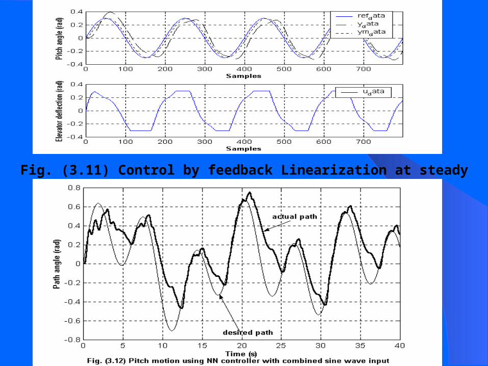
Fig. (3.11) Control by feedback Linearization at steady state flight


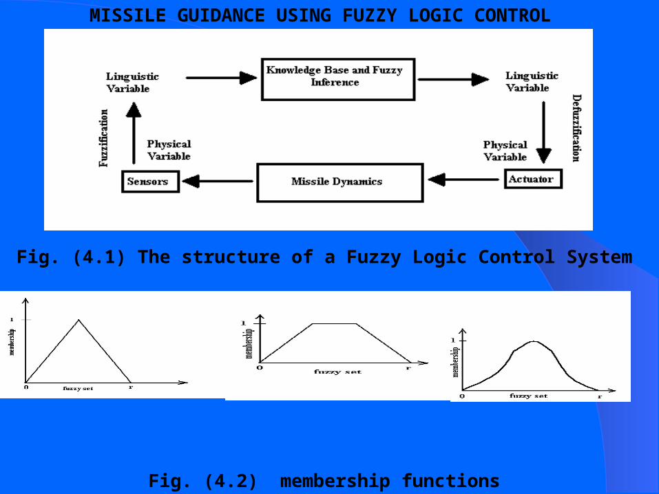
Fig. (4.1) The structure of a Fuzzy Logic Control System
Fig. (4.2) membership functions
MISSILE GUIDANCE USING FUZZY LOGIC CONTROL


Fig. (4.6) Fuzzy matching process
Fig. (4.7) Fuzzy inference process

Fig. (4.8) Fuzzy combination process
Fig. (4.9) Defuzzification process
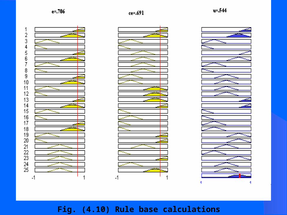
Fig. (4.10) Rule base calculations

Fig. (4.11) Architecture of the generic fuzzy control system

Region 1 2 3 4IF error is P N N P
AND error rate is N N P PTHEN control signal (δu) is Z N Z P
Table (4.1) Control rules for a simple generic fuzzy controller
Fig. (4.12) Step response of a simple generic fuzzy controller
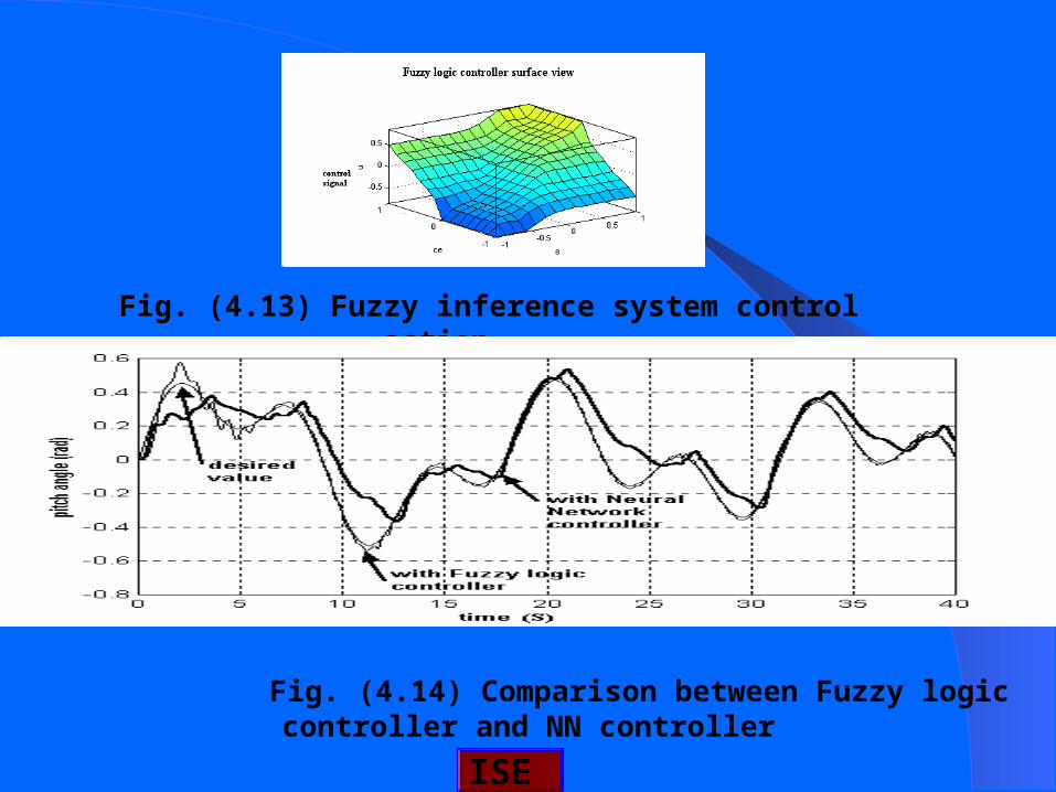
Fig. (4.13) Fuzzy inference system control action
Fig. (4.14) Comparison between Fuzzy logic controller and NN controller
ISE

Fig. (4.15) Effect of normalized and denormalized factors
Fig. (4.16) Comparison between PD and FL controllers with combined sine wave input for pitch motion
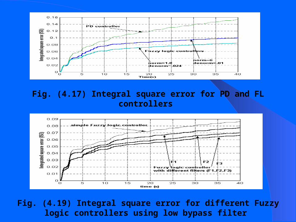
Fig. (4.17) Integral square error for PD and FL controllers
Fig. (4.19) Integral square error for different Fuzzy logic controllers using low bypass filter

Fig. (4.20) Error rate using filter
Fig. (4.21) Error rate using delay only
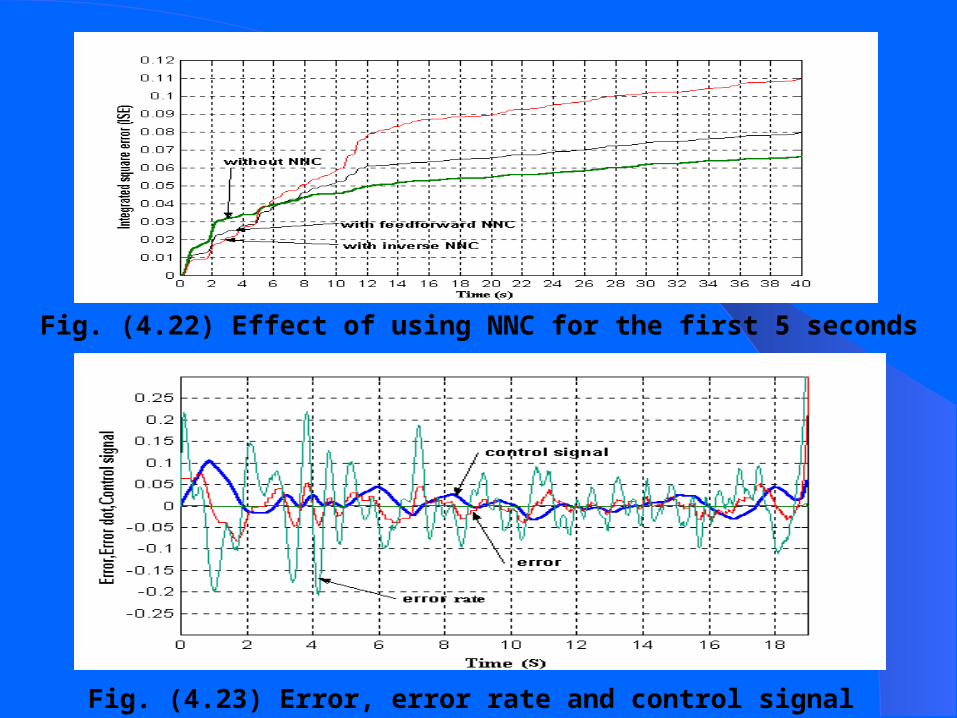
Fig. (4.22) Effect of using NNC for the first 5 seconds
Fig. (4.23) Error, error rate and control signal

Fig. (4.24) Neuro-fuzzy structure
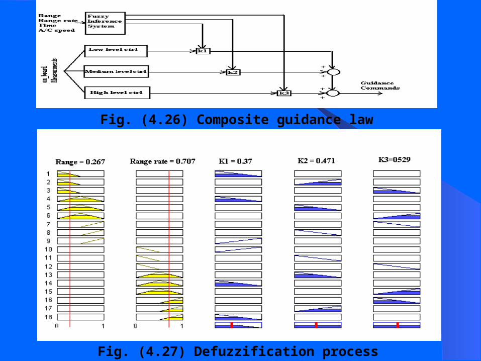
Fig. (4.26) Composite guidance law
Fig. (4.27) Defuzzification process

Fig. (4.28) Fusion Fuzzy system output k1
Fig. (4.29) Fusion Fuzzy system output k2
Fig. (4.30) Fusion Fuzzy system output k3
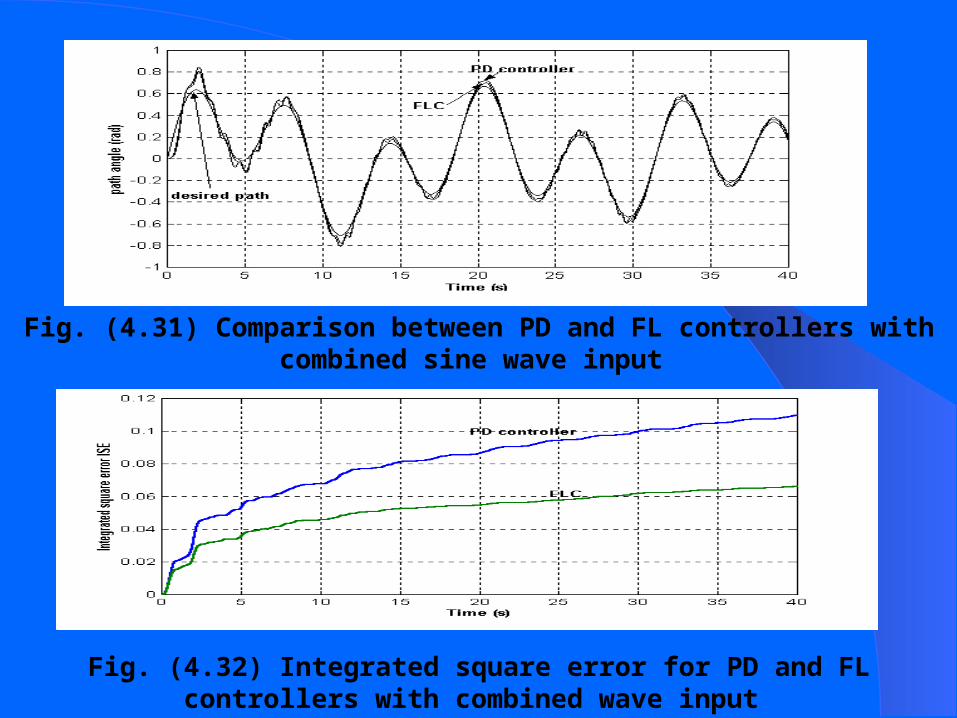
Fig. (4.31) Comparison between PD and FL controllers with combined sine wave input
Fig. (4.32) Integrated square error for PD and FL controllers with combined wave input

Fig. (4.33) Angle of attack using FLC with combined sine wave input
Fig. (4.34) Elevator deflection angle using FLC with combined sine wave input
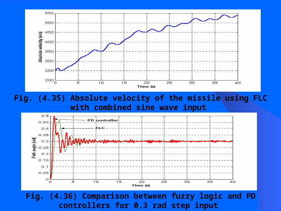
Fig. (4.35) Absolute velocity of the missile using FLC with combined sine wave input
Fig. (4.36) Comparison between fuzzy logic and PD controllers for 0.3 rad step input

Fig. (4.37) Comparison between FLC and PD controller for 0.3 rad step response
Fig. (4.38) Elevator deflection angle for 0.3 step input using FLC

Fig. (4.39) Angle of attack for 0.3 step input using FLC
Fig. (4.40) Absolute velocity for 0.3 step input using FLC

Fig. (4.41) Path angle response using PD, FL controllers with ramp input
Fig. (4.42) Comparison between integrated square error for PD, FL controllers with ramp input
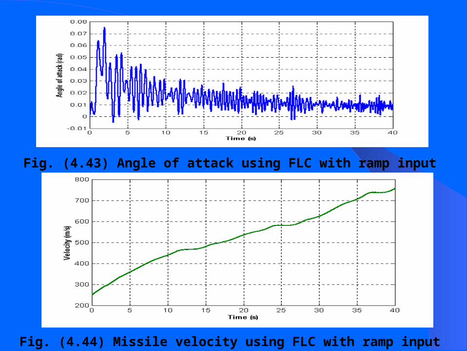
Fig. (4.43) Angle of attack using FLC with ramp input
Fig. (4.44) Missile velocity using FLC with ramp input

Fig. (4.45) Elevator deflection angle using PD, FL controllers with ramp input
Computer simulation
1- F.O.R to body axis transformation
2- Aircraft-missile tracking paths
3- Results and evaluation procedure
4- Final conclusion

F.O.R Body axis to transformation

Fig. A8Aircraft position to missile body axis at F.O.R origin
F.O.R to body axis transformation (1)

Fig. A9 missile body axis shift
F.O.R to body axis transformation (2)

Fig. (5.1) AIM 9 Model with 2 separate controllers
Fig. (5.1) AIM 9 Model with 2 separate controllers
Fig. (5.3) Actual trajectories for target and missile
HYBRID NEUROFUZZY CONTROL SYSTEM FOR MISSSILE GUIDANCE

Fig. (5.4) 3D Plot for missile trajectory in both X,Y axes with respect to time
Fig. (5.5) 3D Plot for missile trajectory in both X, Z axes with respect to time


Fig. (5.6) Calculation of maximum fuse distance in according to simulation data

Fig. (5.8) Error in Y direction due to SSA, control system error
Fig. (5.7) Error in Z direction due to AOA, control system error

Table (6.1) ISE for PD, NN, FL controllers
Controller type Step input Ramp input Combined sine wave input
PD controller .00388 .00633 .112NNC --- --- 1.75FLC .00318 .00580 .066
Table (6.2) Comparison between combined (NNC, FLC) and fuzzy logic controllers for combined sine wave input.Type of controller ISE after
1 SecISE after 2 Sec
ISE after 3 Sec
ISE after 4 Sec
ISE after 5 Sec
ISE at the end of the mission
Combined controller
.009 .011 .020 .027 .035 .112
FLC .017 .020 .032 .034 .035 .066

6.4 Recommendations for Future Work
1-Practical application of the control techniques in this work in collaboration with the ministry of defense is highly recommended.
2-Optimization of the guidance system of the air-to-air missile according to the target maneuver data (predicted path, velocity and acceleration). This will require multiple types of guidance techniques verifying the best performance at any target-missile regime.

Thank you