DEVELOPMENT OF MULTIFUNCTIONAL STRUCTURAL ENERGY STORAGE …
9
ECCM18 - 18 th European Conference on Composite Materials Athens, Greece, 24-28 th June 2018 1 A. Masouras, D. Giannopoulos and V. Kostopoulos DEVELOPMENT OF MULTIFUNCTIONAL STRUCTURAL ENERGY STORAGE DEVICES USING GRAPHENE NANOPLATELETS Athanasios Masouras 1 , Dimosthenis Giannopoulos 1 and Vassilis E. Kostopoulos 1 1 Applied Mechanics Laboratory, Department of Mechanical Engineering and Aeronautics, University of Patras, Rion University Campus, Patras, Greece Email: [email protected], Web Page: http:// http://www.aml.mech.upatras.gr Keywords: Multifunctional Composites, Graphene Nanoplatelets, Manganese Dioxide, Energy Storage, Supercapacitors Abstract Graphene, a class of two-dimensional allotrope of carbon-based materials, is emerged as exciting novel material that has notable application in various fields. Due to its high specific surface area, good chemical stability and outstanding electrical properties, graphene is one of ideal candidates for next generation storage devices. In the present investigation, various types of hybrid formation electrodes, consisting of graphene nanoplatelets and different weight ratios of MnO2 particles were fabricated for application to supercapacitors, to achieve higher specific capacitance combined with mechanical robustness. The morphology and thickness of the graphene electrodes were characterized by Scanning Electron Microscopy. Experiments on structural integrity and energy storage capacity of the electrodes were also carried out. Quasi solid-state electrolytes, consisting of different wt% loadings of succinonitrile (SN) as plasticizer and the ionic liquid 1-butyl-3-methylimidazolium tetrafluoroborate (BMImBF4) entrapped within the structure of copolymer poly vinylidenefluoride-hexafluoropropylene (PVDF-HFP), were prepared to be utilized as ionic conductors in supercapacitors. The ionic liquid concentration varied to investigate the effect on the ionic conductivity of the device while the addition of the plasticizer produced a more compact device. Differential scanning calorimetry (DSC) was used to characterize the thermal stabilities of the electrolytes. DSC studies confirmed that polymer electrolytes remain stable in the same phase over a wide temperature range of -40 to 100 °C. The configuration of supercapacitor started by impregnating carbon fibers with the graphene paste, creating this way composite electrodes. Polymer electrolyte was then applied and solidified between graphene electrodes. A compact supercapacitor was assembled finally by using glass fibers as separator impregnated with electrolyte to avoid contact of the electrodes. The electrochemical behavior of the supercapacitors was evaluated by cyclic voltammetry and galvanostatic charge/discharge. The maximum value of specific capacitance achieved using polymer electrolyte was ~160 F/g. Finally, tensile experiments were performed at ambient conditions to determine the mechanical behavior of the supercapacitors. The results of this study are very promising for the development of materials with high performance in the field of energy storage with applications to wearable electronics.
Transcript of DEVELOPMENT OF MULTIFUNCTIONAL STRUCTURAL ENERGY STORAGE …

ECCM18 - 18th European Conference on Composite Materials
Athens, Greece, 24-28th June 2018 1
A. Masouras, D. Giannopoulos and V. Kostopoulos
DEVELOPMENT OF MULTIFUNCTIONAL STRUCTURAL ENERGY
STORAGE DEVICES USING GRAPHENE NANOPLATELETS
Athanasios Masouras1, Dimosthenis Giannopoulos1 and Vassilis E. Kostopoulos1
1Applied Mechanics Laboratory, Department of Mechanical Engineering and Aeronautics, University
of Patras, Rion University Campus, Patras, Greece
Email: [email protected], Web Page: http:// http://www.aml.mech.upatras.gr
Keywords: Multifunctional Composites, Graphene Nanoplatelets, Manganese Dioxide, Energy
Storage, Supercapacitors
Abstract
Graphene, a class of two-dimensional allotrope of carbon-based materials, is emerged as exciting
novel material that has notable application in various fields. Due to its high specific surface area, good
chemical stability and outstanding electrical properties, graphene is one of ideal candidates for next
generation storage devices. In the present investigation, various types of hybrid formation electrodes,
consisting of graphene nanoplatelets and different weight ratios of MnO2 particles were fabricated for
application to supercapacitors, to achieve higher specific capacitance combined with mechanical
robustness. The morphology and thickness of the graphene electrodes were characterized by Scanning
Electron Microscopy. Experiments on structural integrity and energy storage capacity of the electrodes
were also carried out. Quasi solid-state electrolytes, consisting of different wt% loadings of
succinonitrile (SN) as plasticizer and the ionic liquid 1-butyl-3-methylimidazolium tetrafluoroborate
(BMImBF4) entrapped within the structure of copolymer poly vinylidenefluoride-hexafluoropropylene
(PVDF-HFP), were prepared to be utilized as ionic conductors in supercapacitors. The ionic liquid
concentration varied to investigate the effect on the ionic conductivity of the device while the addition
of the plasticizer produced a more compact device. Differential scanning calorimetry (DSC) was used
to characterize the thermal stabilities of the electrolytes. DSC studies confirmed that polymer
electrolytes remain stable in the same phase over a wide temperature range of -40 to 100 °C. The
configuration of supercapacitor started by impregnating carbon fibers with the graphene paste, creating
this way composite electrodes. Polymer electrolyte was then applied and solidified between graphene
electrodes. A compact supercapacitor was assembled finally by using glass fibers as separator
impregnated with electrolyte to avoid contact of the electrodes. The electrochemical behavior of the
supercapacitors was evaluated by cyclic voltammetry and galvanostatic charge/discharge. The
maximum value of specific capacitance achieved using polymer electrolyte was ~160 F/g. Finally,
tensile experiments were performed at ambient conditions to determine the mechanical behavior of the
supercapacitors. The results of this study are very promising for the development of materials with high
performance in the field of energy storage with applications to wearable electronics.

ECCM18 - 18th European Conference on Composite Materials
Athens, Greece, 24-28th June 2018 2
A. Masouras, D. Giannopoulos and V. Kostopoulos
1. Introduction
The development of polymer fiber composites over decades resulted the application of these
materials to a wide range of applications from civil to military and especially to aerospace industry.
Their comparative advantages offer the feasibility of more efficient structural design for lighter
structures due to their high specific mechanical properties. Also, the manufacturing processes of
polymer fiber composites are suitable for the design and production of tailor-made materials with
optimum stiffness and strength. The last years, extensive efforts have been consumed on the
development of polymer composites with enhanced multifunctionality. Multifunctional composites
combine the unique properties of structural fiber composite materials with at least one additional critical
functionality. The advantages that occur from the development of multifunctional composites have
attracted high research and industry interest over the last years for a variety of applications that demand
enhanced mechanical, electrical, electromagnetic, optical, electromagnetic and chemical properties.
Nanotechnology contributed an important role on the development of multifunctional composite
materials high enhanced properties [1]–[3]. The research on nano-enabled hierarchically multiscale
reinforced composites led to the development of materials with high-end integrated technological
functionalities such as self-sensing [4]–[6] based on the exploitation of the piezoresistive behavior of
nanomaterials. Also, nanotechnology has opened the opportunity of the further research of
multifunctional materials with integrated energy functionalities [7]–[12]. The idea of moving the
necessary energy devices of a structure into the structure in order to save space and weight for additional
energy storage or payload increases the endurance and the capabilities of the mission that the referenced
structure is able to conduct. In a wide range of industry applications such as electronics, automotive,
UAVs, spaceships, portable and wearable electronics multifunctional structural-power composite
materials can be applied to improve their performance in an overall systemic approach.
Carbon nanomaterials and especially carbon nanotubes and graphene nanoparticles have found
several applications in the field of nano-enabled composite materials due to their extraordinary
properties (mechanical, electrical, thermal etc.). A wide range of multifunctional composites have been
developed by the usage of carbon nanomaterials in different forms [18]–[21] and for several different
applications such as enhanced fracture toughness [22], [23] electrical [24], [25] and thermal
conductivity [26]. In parallel, carbon nanomaterials also exhibit unique properties for their application
to energy conversion and storage devices [27] and have attracted wide interest of the research for the
development of high performance solar cells, fuel cells, batteries and supercapacitors. Especially, after
the discovery of graphene with its ideal properties for energy applications [28], [29], such as high aspect
ratio, rich electronic states, high electrical conductivity, high thermal conductivity, large surface area,
high chemical resistance and robust mechanical properties scientists have consumed a lot of effort to
prove in multiple studies to produce high performance energy devices with graphene. Graphene is a 2D
planar nanostructure with thickness of one atom with carbon atoms packed in honeycomb crystal lattice.
The structure of graphene consists the basic modular structure of all carbon allotropes (buckyballs,
carbon nanotubes, graphite) which widely have been used in the formation of electrodes for energy
applications. Graphene monolayer nanosheets and graphene nanoplatelets with few graphene layers due
to their structure and their properties are very effective electrode materials for fuel cells, rechargeable
batteries and supercapacitors.
In this study, graphene nanoplatelets and metal oxides (MnO2) with polymer binder (PVDF) have
been utilized to form self-standing electrodes in the form of films over a current collector and composite
carbon fabric electrodes for supercapacitors. Graphene nanoplatelets in this study serve as a conductive
substrate of the double layer and pseudocapacitance mechanism of MnO2 in order to form a hybrid
supercapacitor electrode. The electrodes were tested with liquid electrolyte (KOH) and solid-state
polymer electrolyte. The fabrication of graphene/MnO2-carbon fabric with solid electrolyte was used to
form robust supercapacitor devices where can be used as structural energy devices. Carbon fabric in this
device serves as the current collector of the system and in parallel the carrier of the mechanical load.
The electrochemical performance of the produced electrodes and devices was studied with potentiostatic
and galvanostatic techniques (Cyclic Voltammetry and Charge-Discharge). The microstructure of the
electrodes observed with Scanning Electron Microscopy (SEM). Finally, tensile tests performed to
characterize the structural integrity of these multifunctional composite energy devices.

ECCM18 - 18th European Conference on Composite Materials
Athens, Greece, 24-28th June 2018 3
A. Masouras, D. Giannopoulos and V. Kostopoulos
2. Experimental
2.1. Materials
1-Methyl-2-pyrrolidinone (NMP, ReagentPlus® grade, 99%, Sigma-Aldrich), pellets of
poly(vinylidene fluoride) (PVdF, Mw ~180,000, Mn ~71,000, Sigma-Aldrich), graphene nanoplatelets
with 8-15nm average thickness (GNPs, 97%, , CheapTubes), activated manganese(IV) oxide powder
(MnO2, , ~85%, <10 μm, Sigma-Aldrich), carbon fabric (plain,160 gr/sqm, FIBERMAX LTD), co-
polymer poly(vinylidenefluoride hexafluoropropylene) (PVdF-HFP, Mw ~400,000, Sigma-Aldrich),
ionic liquid 1-butyl-3-methylimidazolium tetrafluoroborate (BMImBF4, ≥98.0%, Sigma-Aldrich) and
succinonitrile (SN, 99%, Sigma-Aldrich), acetone (ACS reagent, ≥99.7%) and glass fabric (280 g/m2,
twill weave, R&G Germany) have been used without further purification.
2.2. Preparation of Graphene Nanoplatelet-MnO2 Electrodes
The slurry preparation was initiated by magnetic stirring of the polymer binder PVDF with NMP
solvent, until the complete dissolution. The GNPs and MnO2 particles were then added, and their
dispersion was carried out by sonication until a macroscopically homogeneous mixture was obtained.
The mixture was then casted of aluminum substrate and left for drying of the solvent for 3 h. Finally,
three compositions of films were prepared as electrodes for supercapacitors, as listed below :
Table 1: List of hybrid MnO2/GNP electrodes.
Sample
Type
GNP
% wt.
MnO2
% wt.
PVDF
% wt.
MnO2-1 68 12 20
MnO2-2 52 28 20
MnO2-3 40 40 20
2.3. Preparation of SN-based gel polymer electrolytes
Quasi-solid-state electrolytes of copolymer PVdF-HFP with ionic liquid BMImBF4 and plasticizer
SN have been prepared by means of solution mixing method using acetone as solvent. Specifically, 500
mg of PVdF-HFP were separately dissolved in 8 ml acetone under continuous magnetic stirring in sealed
glass vessel. Different wt% loadings of SN and IL were prepared in another vessel. Each IL/SN mixture
was then mixed with the PVdF-HFP solution and stirred continuously for 5 hours until their complete
dissolution. The weight ratio of the PVdF-HFP to IL/SN was kept at 1:4. The electrolytes were finally
stored in sealed vessels until their incorporation in supercapacitors.
2.4. Assembly of solid-state supercapacitor cells
Stepwise fabrication of solid-state supercapacitors with different composition of gel polymer
electrolytes is illustrated in Figure. In order to get optimum graphene/MnO2-electrolyte interface, instead
of sandwiching a membrane between two carbon electrodes, each electrode was impregnated with
electrolyte, while in a low viscosity solution form, before assembling the supercapacitors. Impregnation
of fiber composite electrodes was performed by adding a diluted acetone electrolytic solution into porous
graphene electrodes using a micropipette. Before the completely evaporation of acetone, a glass fabric
was put over the liquid electrolyte solution and impregnated with this. Here, the soaked glass fabric
allows the ion movements and separates the electrodes from any danger of undesirable short-circuits.
Finally, a drop of electrolytic solution was added before the two identical electrodes were assembled in
a planar configuration to form the solid-state cell. In all cases, the supercapacitors active area was 1 cm2
and the active mass of each electrode was 0.6-1.5 mg/cm2. As a counter electrode in any case was used
an electrode which was formed with GNPs and PVDF (80% wt. GNPs and 20% PVDF) without MnO2.
The purpose of the usage of this kind of counter electrode is to use the same conductive substrate in both
electrodes. A slurry was formed with GNPs and PVDF and was injected on carbon fabric to the carbon
fiber electrode and in the case of film electrodes was tape-casted on aluminum substrate. So, the final

ECCM18 - 18th European Conference on Composite Materials
Athens, Greece, 24-28th June 2018 4
A. Masouras, D. Giannopoulos and V. Kostopoulos
formation of the supercapacitor is a non symmetrical supercapacitor with a hybrid GNP/MnO2 and a
GNP electrode.
Figure 1: Manufacturing process of carbon fober/GNP/MnO2 electrodes and assembly of the
supercapacitor.
2.5. Measurements
Differential scanning calorimetry (DSC) was used to test the thermal stability of the gel electrolytes.
DSC was performed from -80 to 200 oC at a heating rate of 10 oC/min in a static nitrogen atmosphere
using DSC 2920 (TA Instruments). The microstructure and morphology of the porous graphene-based
composite electrodes was estimated by SEM (LEO SUPRA 35VP). Electrochemical performance of the
supercapacitor cells was tested by cyclic voltammetry (CV) and galvanostatic charge-discharge method
using an AUTOLAB potentiostat/galvanostat analyzer (PGSTAT302N - High Performance). The
electrochemical performance of the liquid state supercapacitor cells was performed in a 3-electrode
configuration set-up, using 1M KOH electrolyte. To estimate the capacitive response of the fabricated
solid-state supercapacitors with the different compositions of gel electrolytes, a set-up with two
symmetrical Cu contacts in a parallel configuration was assembled. The CV was carried out at different
scan rates (10, 20, 50, 100, 200 mV/s) between a potential range of 0 and 2.5 V.The galvanostatic
charge/discharge tests were performed at different constant current density from 0.3 A/g to 8 A/g in the
potential range of 0 - 2.5 V. To estimate the mechanical behavior of the solid-state supercapacitors, the
Instron 8872 fatigue testing system was used. Tensile experiments were carried out at ambient
conditions with elongation rate of 1 mm/min.
3. Results and Discussion
Electrolytes with good mechanical stability are a necessary prerequisite for the fabrication of
structural supercapacitors. The fundamental concept of solid-state electrolytes involves the
immobilization of ionic liquids, with high electrochemical potential window and low vapor pressure,
using a small amount of polymer materials. The copolymer PVDF-HFP has been shown to be a
promising matrix for an electrolyte material due to its good mechanical properties. However, since the
electrochemical devices involve ion movements in the cell, the high crystallinity of PVDF-HFP leads to
the decrease in ionic mobility and subsequently to lower power performance of the devices. In this way,
the solid plasticizer SN was used to enhance the ionic conductivity of the polymer electrolytes. Plastic-
crystalline SN possesses high molecular diffusivity, waxy nature, and good solvating power via low
melting temperature and high dielectric constant (ε ~ 55) which help to reduce the crystallinity of PVdF-
HFP. Finally, gel polymer electrolytes with high ionic mobility and good dimensional/mechanical
stability were prepared. An optical image of a self-standing electrolyte film, which combine both flexible
nature and transparency is shown in Figure 9.
The microstrure of the film electrodes and the carbon fiber electrodes was investigated by SEM. In
Figure 2 (magnification ~600x) was captured the cross sectional area of the film electrode through the
thickness, the thickness of the film was measured at approximately 30 μm. In Figure 3 to Figure 5 at
higher magnifications is presented the internal microstructure of the film electrodes were the GNP and
MnO2 particles are distributed uniformerly all over the structure of the film. The morphology of the
carbon fabrics after the impregnation process that was followed to deposit GNP/MnO2 particles over the
fiber surface is presented in Figure 6: and Figure 7. Also, in this case GNPs and MnO2 are distributed
all over the carbon fabric.

ECCM18 - 18th European Conference on Composite Materials
Athens, Greece, 24-28th June 2018 5
A. Masouras, D. Giannopoulos and V. Kostopoulos
Figure 2: Magnification ~600x,
cross section of the film
electrodes
Figure 3: Magnification ~1.3Kx,
microstructure of the film
Figure 4: Magnification ~2.7Kx,
microstructure of the film
Figure 5: Magnification ~3.5Kx,
microstructure of the film
Figure 6: Magnification ~160x,
distribution of the GNP/MnO2
particles over the carbon fabric
Figure 7: Magnification ~1Kx,
microstructure of the carbon fiber
electrode
Figure 8: DSC curves for different compositions of polymer
electrolyte
Figure 9: Morphology of the
solid polymer electrolyte
The thermal stability of the SN-based gel polymer electrolytes was tested by DSC. DSC curves
were obtained from first run heating. Figure 8 shows the DSC thermograms of the different
compositions of PVdF-HFP/IL/SN gel electrolytes, as well as of the polymer PVdF, the host co-polymer
PVdF-HFP and the pure SN. Pure SN shows two characteristics peaks at -35 oC and 60 oC. The peak at
~ -35 oC corresponds to the glass transition temperature, and the peak at ~60 oC is assigned as melting
temperature of SN. The endothermic peak at 168 oC corresponds to the melting point of crystalline phase
of PVdF. The host polymer PVdF-HFP shows melting point at 142 oC, due to the amorphous phase of
HFP. By adding IL, the melting point of the different compositions of PVdF-HFP/IL/SN gel electrolytes
is decreased in a temperature range from 135 to 120 oC, and this is attributed to the presence of liquid
components that causes an increase in the amorphous content in the overall phase of the electrolytes. On
addition of SN, there is no melting peak of SN appears for gel-SN1 and gel-SN2 whereas for gel-SN3
the melting peak of SN shifted from 60 to 9 oC. The most thermostable composition of the polymer
electrolyte obtained in the sample SN1 with melting point at ~135 oC.
The electrochemical behavior of the produced electrode materials was characterized with
potentiostatic and galvanostatic measurements. Cyclic voltammetry and charge-discharge tests were

ECCM18 - 18th European Conference on Composite Materials
Athens, Greece, 24-28th June 2018 6
A. Masouras, D. Giannopoulos and V. Kostopoulos
conducted to measure the specific capacitance of the electrodes and to evaluate their overall
electrochemical behavior. Film electrodes were characterized with a three electrode setup and liquid
electrolyte (1M KOH) and for the solid state electrolyte tests were assembled asymmetrical
supercapacitor cells. From Figure 10 to Figure 12 are presented the results of cyclic voltammetry tests
for the film elctrodes (MnO2-1, MnO2-2, MnO2-3). In all cases pseudocapaciatance mechanism was
confirmed by the curves exported from cyclic voltammetry. Most intense pseudocapacitance mechanism
was observed in sample MnO2-2 Figure 11. The maximum specific capacitance obtained from the film
samples is 141 F/g, 266 F/g and 318 F/g respectively. In sample MnO2-3 specific drops abruptly as the
scan rate increases. From Figure 13 to Figure 15 presest the curves that obtained from charge-discharge
tests with the same liquid electrolyte at potential window of 0.55V. In Figure 17 are concentrated the
values of specific capacitance that calculated from charge-discharge tests correlated with the current
density. It is confirmed that sample MnO2-3 has an abrupt dropage of the specific capacitance as current
density increases and also has a very high specific capacitance of ~450 F/g at 0.3 A/g current density.
More stable behavior with retention of high specific capacitance values is sample MnO2-2. The
formulation of sample MnO2-2 was selected to supercapacitor with polymer electrolyte.
Figure 10: CV curve of sample
MnO2-1
Figure 11: CV curve of sample
MnO2-2
Figure 12: CV curve of
sample MnO2-3
Figure 13: Charge-Discharge curve
of sample MnO2-1
Figure 14: Charge-Discharge curve
of sample MnO2-2
Figure 15: Charge-Discharge
curve of sample MnO2-3
Figure 16: Specific Capacitance evolution vs Scan
Rate
Figure 17: Specific Capacitance evolution vs
Current Density
0,0 0,1 0,2 0,3 0,4 0,5 0,6 0,7
-0,015
-0,010
-0,005
0,000
0,005
0,010
0,015
Cu
rre
nt
(A)
Potential (V)
10 mV/s
20 mV/s
50 mV/s
100 mV/s
200 mV/s
0,0 0,1 0,2 0,3 0,4 0,5 0,6 0,7
-0,04
-0,02
0,00
0,02
0,04
0,06
Curr
ent (A
)
Potential (V)
10 mV/s
20 mV/s
50 mV/s
100 mV/s
200 mV/s
-0,1 0,0 0,1 0,2 0,3 0,4 0,5 0,6 0,7 0,8
-0,02
-0,01
0,00
0,01
0,02
0,03
Curr
ent (A
)
Potential (V)
10 mV/s
20 mV/s
50 mV/s
100 mV/s
200 mV/s
0 100 200 300 400 500 600
0,0
0,1
0,2
0,3
0,4
0,5
0,6
Po
ten
tial (
V)
Time (s)
0,5 A/g
1 A/g
3 A/g
5 A/g
0 200 400 600 800 1000
0,0
0,1
0,2
0,3
0,4
0,5
0,6
Po
tentia
l (V
)
Time (s)
0,35 A/g
0,7 A/g
2,1 A/g
3,5 A/g
0 200 400 600 800 1000 1200 1400 1600 1800 2000
0,0
0,1
0,2
0,3
0,4
0,5
0,6
Po
tentia
l (V
)
Time (s)
0,3 A/g
0,6 A/g
1,8 A/g
3 A/g
0 50 100 150 200
0
50
100
150
200
250
300
350
Sp
. C
ap
acita
nce
(F
/g)
Scan Rate (mV/s)
MnO2-1
MnO2-2
MnO2-3
0 1 2 3 4 5
0
50
100
150
200
250
300
350
400
450
500
Sp
, C
ap
acita
nce
(F
/g)
Current Density (A/g)
MnO2-1
MnO2-2
MnO2-3
ECCM18 - 18th European Conference on Composite Materials
Athens, Greece, 24-28th June 2018 7
A. Masouras, D. Giannopoulos and V. Kostopoulos
For the assembly of the polymer solid electrolyte supercapacitor (SESC) used MnO2-2 samlpe and
a counter electrode consisted of GNPs and PVDF (80% GNPs). In Figure 18 in presented the CV that
obtained at the same scan rates that used for the aqueous liquid electrode but in this case in wider
potential window (0-2.5V) that is operational for the polymer electrolyte. The elecrochemical behavior
of the sample differs from the behavior that obtained for the same sample with aqueous liquid electrolyte.
The pseudocapacitance mechanism is restricted by the limitations that insert the solid electrolyte on the
ionic mobility and as a result the maximum specific cpapacitance measured at ~151.2 F/g. Figure 19
presents the CV curve of the carbon fiber composite solid electrolyte supercapcitor (CF-SESC) which
is similar to the curve extracted for the sample without carbon fibers. The specific capacitance measured
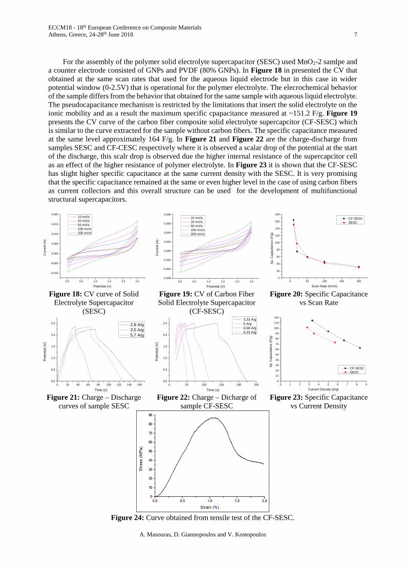
at the same level approximately 164 F/g. In Figure 21 and Figure 22 are the charge-discharge from
samples SESC and CF-CESC respectively where it is observed a scalar drop of the potential at the start
of the discharge, this scalr drop is observed due the higher internal resistance of the supercapcitor cell
as an effect of the higher resistance of polymer electrolyte. In Figure 23 it is shown that the CF-SESC
has slight higher specific capacitance at the same current density with the SESC. It is very promising
that the specific capacitance remained at the same or even higher level in the case of using carbon fibers
as current collectors and this overall structure can be used for the development of multifunctional
structural supercapacitors.
Figure 18: CV curve of Solid
Electrolyte Supercapacitor
(SESC)
Figure 19: CV of Carbon Fiber
Solid Electrolyte Supercapacitor
(CF-SESC)
Figure 20: Specific Capacitance
vs Scan Rate
Figure 21: Charge – Discharge
curves of sample SESC
Figure 22: Charge – Dicharge of
sample CF-SESC
Figure 23: Specific Capacitance
vs Current Density
Figure 24: Curve obtained from tensile test of the CF-SESC.
0,0 0,5 1,0 1,5 2,0 2,5
-0,010
-0,005
0,000
0,005
0,010
0,015
0,020
Cu
rre
nt
(A)
Potential (V)
10 mV/s
20 mV/s
50 mV/s
100 mV/s
200 mV/s
0,0 0,5 1,0 1,5 2,0 2,5
-0,006
-0,004
-0,002
0,000
0,002
0,004
0,006
0,008
Cu
rre
nt
(A)
Potential (V)
10 mV/s
20 mV/s
50 mV/s
100 mV/s
200 mV/s
0 50 100 150 200
0
20
40
60
80
100
120
140
160
180
Sp
. C
ap
acita
nce
(F
/g)
Scan Rate (mV/s)
CF-SESC
SESC
0 20 40 60 80 100 120 140 160
0,0
0,5
1,0
1,5
2,0
2,5
Po
tentia
l (V
)
Time (s)
2,8 A/g
3,5 A/g
5,7 A/g
0 50 100 150 200 250
0,0
0,5
1,0
1,5
2,0
2,5
Po
tentia
l (V
)
Time (s)
3,33 A/g
5 A/g
6,66 A/g
8,33 A/g
0 1 2 3 4 5 6 7 8 9
0
10
20
30
40
50
60
70
80
90
100
110
120
Sp
. C
ap
acita
nce
(F
/g)
Current Density (A/g)
CF-SESC
SESC
ECCM18 - 18th European Conference on Composite Materials
Athens, Greece, 24-28th June 2018 8
A. Masouras, D. Giannopoulos and V. Kostopoulos
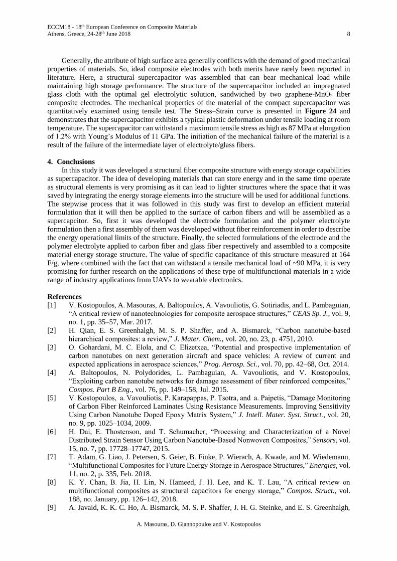
Generally, the attribute of high surface area generally conflicts with the demand of good mechanical
properties of materials. So, ideal composite electrodes with both merits have rarely been reported in
literature. Here, a structural supercapacitor was assembled that can bear mechanical load while
maintaining high storage performance. The structure of the supercapacitor included an impregnated
glass cloth with the optimal gel electrolytic solution, sandwiched by two graphene-MnO2 fiber
composite electrodes. The mechanical properties of the material of the compact supercapacitor was
quantitatively examined using tensile test. The Stress–Strain curve is presented in Figure 24 and
demonstrates that the supercapacitor exhibits a typical plastic deformation under tensile loading at room
temperature. The supercapacitor can withstand a maximum tensile stress as high as 87 MPa at elongation
of 1.2% with Young’s Modulus of 11 GPa. The initiation of the mechanical failure of the material is a
result of the failure of the intermediate layer of electrolyte/glass fibers.
4. Conclusions
In this study it was developed a structural fiber composite structure with energy storage capabilities
as supercapacitor. The idea of developing materials that can store energy and in the same time operate
as structural elements is very promising as it can lead to lighter structures where the space that it was
saved by integrating the energy storage elements into the structure will be used for additional functions.
The stepwise process that it was followed in this study was first to develop an efficient material
formulation that it will then be applied to the surface of carbon fibers and will be assemblied as a
supercapcitor. So, first it was developed the electrode formulation and the polymer electrolyte
formulation then a first assembly of them was developed without fiber reinforcement in order to describe
the energy operational limits of the structure. Finally, the selected formulations of the electrode and the
polymer electrolyte applied to carbon fiber and glass fiber respectively and assembled to a composite
material energy storage structure. The value of specific capacitance of this structure measured at 164
F/g, where combined with the fact that can withstand a tensile mechanical load of ~90 MPa, it is very
promising for further research on the applications of these type of multifunctional materials in a wide
range of industry applications from UAVs to wearable electronics.
References
[1] V. Kostopoulos, A. Masouras, A. Baltopoulos, A. Vavouliotis, G. Sotiriadis, and L. Pambaguian,
“A critical review of nanotechnologies for composite aerospace structures,” CEAS Sp. J., vol. 9,
no. 1, pp. 35–57, Mar. 2017.
[2] H. Qian, E. S. Greenhalgh, M. S. P. Shaffer, and A. Bismarck, “Carbon nanotube-based
hierarchical composites: a review,” J. Mater. Chem., vol. 20, no. 23, p. 4751, 2010.
[3] O. Gohardani, M. C. Elola, and C. Elizetxea, “Potential and prospective implementation of
carbon nanotubes on next generation aircraft and space vehicles: A review of current and
expected applications in aerospace sciences,” Prog. Aerosp. Sci., vol. 70, pp. 42–68, Oct. 2014.
[4] A. Baltopoulos, N. Polydorides, L. Pambaguian, A. Vavouliotis, and V. Kostopoulos,
“Exploiting carbon nanotube networks for damage assessment of fiber reinforced composites,”
Compos. Part B Eng., vol. 76, pp. 149–158, Jul. 2015.
[5] V. Kostopoulos, a. Vavouliotis, P. Karapappas, P. Tsotra, and a. Paipetis, “Damage Monitoring
of Carbon Fiber Reinforced Laminates Using Resistance Measurements. Improving Sensitivity
Using Carbon Nanotube Doped Epoxy Matrix System,” J. Intell. Mater. Syst. Struct., vol. 20,
no. 9, pp. 1025–1034, 2009.
[6] H. Dai, E. Thostenson, and T. Schumacher, “Processing and Characterization of a Novel
Distributed Strain Sensor Using Carbon Nanotube-Based Nonwoven Composites,” Sensors, vol.
15, no. 7, pp. 17728–17747, 2015.
[7] T. Adam, G. Liao, J. Petersen, S. Geier, B. Finke, P. Wierach, A. Kwade, and M. Wiedemann,
“Multifunctional Composites for Future Energy Storage in Aerospace Structures,” Energies, vol.
11, no. 2, p. 335, Feb. 2018.
[8] K. Y. Chan, B. Jia, H. Lin, N. Hameed, J. H. Lee, and K. T. Lau, “A critical review on
multifunctional composites as structural capacitors for energy storage,” Compos. Struct., vol.
188, no. January, pp. 126–142, 2018.
[9] A. Javaid, K. K. C. Ho, A. Bismarck, M. S. P. Shaffer, J. H. G. Steinke, and E. S. Greenhalgh,
ECCM18 - 18th European Conference on Composite Materials
Athens, Greece, 24-28th June 2018 9
A. Masouras, D. Giannopoulos and V. Kostopoulos
“Multifunctional structural supercapacitors for electrical energy storage applications,” J.
Compos. Mater., vol. 48, no. 12, pp. 1409–1416, May 2014.
[10] L. E. Asp and E. S. Greenhalgh, Multifunctional structural battery and supercapacitor
composites. Elsevier Inc., 2015.
[11] Y. Yu, B. Zhang, M. Feng, G. Qi, F. Tian, Q. Feng, J. Yang, and S. Wang, “Multifunctional
structural lithium ion batteries based on carbon fiber reinforced plastic composites,” Compos.
Sci. Technol., vol. 147, pp. 62–70, 2017.
[12] R. F. Gibson, “A review of recent research on mechanics of multifunctional composite materials
and structures,” Compos. Struct., vol. 92, no. 12, pp. 2793–2810, Nov. 2010.
[13] A. Paipetis, V. Kostopoulos, A. Vavouliotis, P. Karapappas, P. Tsotra, C. Jaillet, N. D.
Alexopoulos, P. Poulin, S. Grishchuk, R. Schledjewski, D. Giliopoulos, K. Triantafyllidis, D.
Gournis, T. C. Theodosiou, D. A. Saravanos, and N.-M. Barkoula, Carbon Nanotube Enhanced
Aerospace Composite Materials. Springer, 2013.
[14] A. Masouras, A. Vavouliotis, A. Baltopoulos, V. Kostopoulos, and L. Pambaguian,
“Development of Nanocomposite Material Films and Integration into CFRPs for the
Development of Multifunctional Structures,” 2015, no. July.
[15] H. Wu and L. T. Drzal, “Graphene nanoplatelet paper as a light-weight composite with excellent
electrical and thermal conductivity and good gas barrier properties,” Carbon N. Y., vol. 50, no.
3, pp. 1135–1145, Mar. 2012.
[16] W. Liu, S. Zhang, L. Hao, F. Yang, W. Jiao, X. Li, and R. Wang, “Fabrication of carbon
nanotubes/carbon fiber hybrid fiber in industrial scale by sizing process,” Appl. Surf. Sci., vol.
284, pp. 914–920, Nov. 2013.
[17] C. Fang, J. Wang, and T. Zhang, “Interlaminar improvement of carbon fiber/epoxy composites
via depositing mixture of carbon nanotubes and sizing agent,” Appl. Surf. Sci., vol. 321, pp. 1–
9, Dec. 2014.
[18] M. Fogel, P. Parlevliet, M. Geistbeck, P. Olivier, and É. Dantras, “Thermal, rheological and
electrical analysis of MWCNTs/epoxy matrices,” Compos. Sci. Technol., vol. 110, pp. 118–125,
Apr. 2015.
[19] V. B. Mohan, K. tak Lau, D. Hui, and D. Bhattacharyya, “Graphene-based materials and their
composites: A review on production, applications and product limitations,” Compos. Part B
Eng., vol. 142, no. January, pp. 200–220, 2018.
[20] J. Phiri, P. Gane, and T. C. Maloney, “General overview of graphene: Production, properties and
application in polymer composites,” Mater. Sci. Eng. B Solid-State Mater. Adv. Technol., vol.
215, pp. 9–28, 2017.
[21] W. Li, A. Dichiara, and J. Bai, “Carbon nanotube–graphene nanoplatelet hybrids as high-
performance multifunctional reinforcements in epoxy composites,” Compos. Sci. Technol., vol.
74, pp. 221–227, Jan. 2013.