
Analysis and optimization of fume extraction from a ferromanganese ...
May 21, 2001
42539Final.report.doc
Development of Lightweight Fume Extraction Welding Guns
Submitted to:
National Shipbuilding Research Program SP-7 Welding Panel
Submitted by:
David Yapp, John Lawmon, Harvey Castner Edison Welding Institute
1250 Arthur E. Adams Drive Columbus, OH 43221
Report Documentation Page Form ApprovedOMB No. 0704-0188
Public reporting burden for the collection of information is estimated to average 1 hour per response, including the time for reviewing instructions, searching existing data sources, gathering andmaintaining the data needed, and completing and reviewing the collection of information. Send comments regarding this burden estimate or any other aspect of this collection of information,including suggestions for reducing this burden, to Washington Headquarters Services, Directorate for Information Operations and Reports, 1215 Jefferson Davis Highway, Suite 1204, ArlingtonVA 22202-4302. Respondents should be aware that notwithstanding any other provision of law, no person shall be subject to a penalty for failing to comply with a collection of information if itdoes not display a currently valid OMB control number.
1. REPORT DATE 21 MAY 2001
2. REPORT TYPE N/A
3. DATES COVERED -
4. TITLE AND SUBTITLE Development of Lightweight Fume Extraction Welding Guns
5a. CONTRACT NUMBER
5b. GRANT NUMBER
5c. PROGRAM ELEMENT NUMBER
6. AUTHOR(S) 5d. PROJECT NUMBER
5e. TASK NUMBER
5f. WORK UNIT NUMBER
7. PERFORMING ORGANIZATION NAME(S) AND ADDRESS(ES) Naval Surface Warfare Center CD Code 2230-Design Integration ToolsBldg 192, Room 128 9500 MacArthur Blvd Bethesda, MD 20817-5700
8. PERFORMING ORGANIZATIONREPORT NUMBER
9. SPONSORING/MONITORING AGENCY NAME(S) AND ADDRESS(ES) 10. SPONSOR/MONITOR’S ACRONYM(S)
11. SPONSOR/MONITOR’S REPORT NUMBER(S)
12. DISTRIBUTION/AVAILABILITY STATEMENT Approved for public release, distribution unlimited
13. SUPPLEMENTARY NOTES
14. ABSTRACT
15. SUBJECT TERMS
16. SECURITY CLASSIFICATION OF: 17. LIMITATION OF ABSTRACT
SAR
18. NUMBEROF PAGES
45
19a. NAME OFRESPONSIBLE PERSON
a. REPORT unclassified
b. ABSTRACT unclassified
c. THIS PAGE unclassified
Standard Form 298 (Rev. 8-98) Prescribed by ANSI Std Z39-18
42539FR/01
i
Contents
Page Executive Summary .....................................................................................................................iii 1.0 Introduction ........................................................................................................................... 1 2.0 Technical Approach .............................................................................................................. 1 3.0 Literature Review ................................................................................................................... 2
3.1 Basic Principles of Welding Fume Extraction Guns .......................................................... 2 3.2 Early Development of Fume Extracting Guns ................................................................... 3 3.3 Operation of Fume Extracting Guns .................................................................................. 4
3.3.1 Gas Flow and Electrode Stickout ................................................................................ 5 3.3.2 Exhaust Conditions .....................................................................................................5
3.4 Evaluating Gun Extraction Efficiency ................................................................................ 6 3.5 Welding Gun Ergonomics .................................................................................................. 9 3.6 Commercial Equipment ................................................................................................... 11 3.7 Application Experience .................................................................................................... 11
4.0 Summary of Fume Extraction Gun Experience in U.S. Shipyards ...................................... 12 5.0 Evaluation of Current Fume Extraction Guns ...................................................................... 13
5.1 Measurement of Fume Extraction Efficiency ................................................................... 13 5.2 Results of Fume Extraction Efficiency Tests ................................................................... 14 5.3 Evaluation of Welder Preference and Gun Ergonomic Factors ....................................... 16 5.4 Results of Welder Preference and Gun Ergonomic Factor Evaluations .......................... 17
6.0 Lightweight Fume Extraction Gun Design Targets .............................................................. 20 7.0 Evaulation of Extraction Equipment ..................................................................................... 21
7.1 Evaluation of the Venturi Concept During Welding ......................................................... 21 7.2 Evaluation of a Commercially Available Fume Extraction System .................................. 22
8.0 - Evaluation of Prototype Gun .............................................................................................. 23 8.1 Comparison of Lightweight and conventional guns ......................................................... 23
9.0 Field Trials .......................................................................................................................... 24 9.1 Newport News ................................................................................................................. 24 9.2 Ingalls Shipbuilding ......................................................................................................... 26 9.3 NASSCO ......................................................................................................................... 26 9.4 Summary of Shipyard Trials ............................................................................................. 28
10.0 Conclusion ........................................................................................................................ 28
TABLES AND FIGURES
Table 1 Exhaust Nozzle Efficiency for BOC System, Measured by Total Fume Collection .....................................................................................................8 Table 2 Capture Efficiency Measurements for Fume Extraction Guns .......................................9 Table 3. Summary of Gun Efficiency Tests ...............................................................................16 Table 4. Gun Efficiency Matrix ...................................................................................................16 Table 5. Ranking of Welder Evaluations of Guns ......................................................................19 Table 6. Air Velocity, Volume, Flow Rates, and Static Pressure Changes for a Commercial Fume Extractor with a 15-ft Long Hose .......................................................................22 Table 7. Air Velocity, Volume, Flow Rates, and Static Pressure Changes for a Commercial Fume Extractor with a 30-ft Long Hose .......................................................................22
42539FR/01
ii
Table 8. Comparison of Lightweight Gun with Design Targets and Standard Fume extraction guns ...............................................................................................23 Table 9. Volume Flow Rates for Gun A and K ...........................................................................24 Figure 1. Semi-Automatic Welding Guns with Integral Fume Extraction; a) Annular Slot Type; b) Multi-Hole Chamber Type ................................................. 30 Figure 2. Fillet Weld - Fume Escapes When Gun Angle is not 45 deg. .................................. 30 Figure 3. Open Corner Weld - Fume Escapes When Shielding Gas is not Turned Back to Extraction Flow Path....................................................................... 31 Figure 4. Alternative Designs of Fume Extraction Nozzles. Values Given are Flow Rates Which Could be Achieved (m3/hr using 22 m Outlet) with Each Nozzle Design Before Suction Affected Shielding Gas Coverage. ................................................................................................................ 31 Figure 5. Bernard 400 amp Fume Gun ................................................................................... 32 Figure 6. Bernard 250A Fume Gun......................................................................................... 32 Figure 7. Binzel 500 amp Fume Gun ...................................................................................... 33 Figure 8. Lincoln Magnum 400 am Fume Gun........................................................................ 33 Figure 9. Lincoln Magnum 250 amp Fume Gun...................................................................... 34 Figure 10. AWS Fume Test Chamber....................................................................................... 35 Figure 11. Fume Gun Extraction Efficiency............................................................................... 36 Figure 12. Welder Score vs. Gun Weight at 60-in..................................................................... 37 Figure 13. Welder Score vs. Gun Weight at 0 in....................................................................... 37 Figure 14. Welder Score vs. 45 deg. Deflection Force ............................................................. 38 Figure 15. Welder Score vs. Handle Circumference................................................................. 38 Figure 16. Welder Score vs. Gun Current Rating ..................................................................... 39 Figure 17. Venturi Pump, Inlet Pressure Regulator, Static Pressure Tappings, Small Bore Tube, and Digital Manometer ............................................... 39
42539FR/01
iii
Executive Summary This report describes a project conducted for the NSRP SP-7 Welding Panel to develop a lightweight fume extraction welding gun for shipyard use. Shipbuilders are interested in fume extraction welding guns to improve worker comfort, meet workplace safety requirements as well as environmental regulations. Current fume extraction welding guns have limited flexibility and are bulky compared to conventional guns. Shipbuilders desire improved fume extraction guns to make them practical for widespread use. The objective of this project was to develop a lightweight fume extraction gun for GMAW and FCAW welding processes that incorporates ergonomic engineering to improve usability. Edison Welding Institute performed the project with participation from Newport News Shipbuilding, Ingalls Shipbuilding, National Steel and Shipbuilding Company, and welding equipment manufacturers. The project gathered past experience with fume extraction welding guns, evaluated current guns, developed a prototype lightweight gun, and evaluated this gun during shipyard trials. Studies of present guns and shipyard needs produced the design goals for an improved lightweight gun. A prototype lightweight fume extraction gun was developed and evaluated in the laboratory and at three shipyards. While the new lightweight gun did not achieve all of the desired design targets, it is an improvement in nearly every category compared to standard fume extraction guns. The weight of the gun itself is between 15 percent and 45 percent lighter than other guns. The flexibility of the hose and cable are dramatically improved. Shipyard user trials show the welders preferred the prototype lightweight gun to the other guns tested on the basis of ergonomic factors. These user trials also show that the fume capture efficiency of the prototype lightweight gun was not as good as conventional fume extraction guns. Poor capture efficiency may be due to the small diameter hose used to help reduce weight and improve flexibility of this gun. Alternatively, the fume extractor may not have been suitable for this gun design. This project shows that improvements can be made to reduce the weight and improve the flexibility of lightweight fume extraction guns. However, additional refinements are needed to improve the fume capture efficiency of the prototype lightweight gun to match currently available guns. This may be accomplished either by improving the hose design, improving the capture nozzle, or by tuning the extractor to improve air flow.
42539FR/01
1
1.0 Introduction Gas metal arc (GMAW) welding and flux cored arc welding (FCAW) processes are used for the majority of welding in many US shipyards. These processes provide higher deposition rates and duty cycle than competing manual processes. GMAW and FCAW both produce fumes, and concern about welding fume is increasing. Regulatory agencies are considering more stringent limits for airborne emissions that can be produced during welding. A recent NSRP study(1) determined lost productivity and other costs of complying to proposed limits for hexavalent chromium at Navy and private shipyards could cost millions of dollars annually. To assure worker comfort and adhere to workplace safety and environmental regulations, shipbuilders are exploring the use of fume extraction guns. These devices incorporate fume capture capability within the hand-held welding gun, reducing the need for separate local extraction equipment or the use of personal respirators by welders. As a result, workers are more productive because they do not have to transport and position extraction equipment each time they work in a new location. Current fume extracting welding guns have limited flexibility and are bulky to handle, when compared to conventional equipment. The next generation of fume extraction guns must both improve the local environment and be easier for the welder to manipulate for extended periods of time. The NSRP SP-7 Welding Panel identified development of lightweight fume extraction guns as a high priority research need as detailed in NSRP RFP 7-98-1. The work described in this report was completed in response to this need. The objective of this project was to develop a lightweight, cooler fume extraction welding gun for GMAW and FCAW welding processes and incorporate ergonomic engineering to improve usability.
2.0 Technical Approach The project was performed in three phases that are described as follows. Phase 1 reviewed the state of practice of existing fume extraction guns and surveyed shipyard requirements for improved gun performance. This phase also determined the weight, flexibility, and fume extraction performance of present fume extraction guns. Design guidelines for an improve fume extraction welding gun were defined in terms of desired weight, flexibility, and fume extraction performance. A prototype lightweight fume extraction gun was developed during Phase 2 of the project and evaluated during Phase 3. Evaluations of the new gun were performed in the laboratory and during shipyard trials.
42539FR/01
2
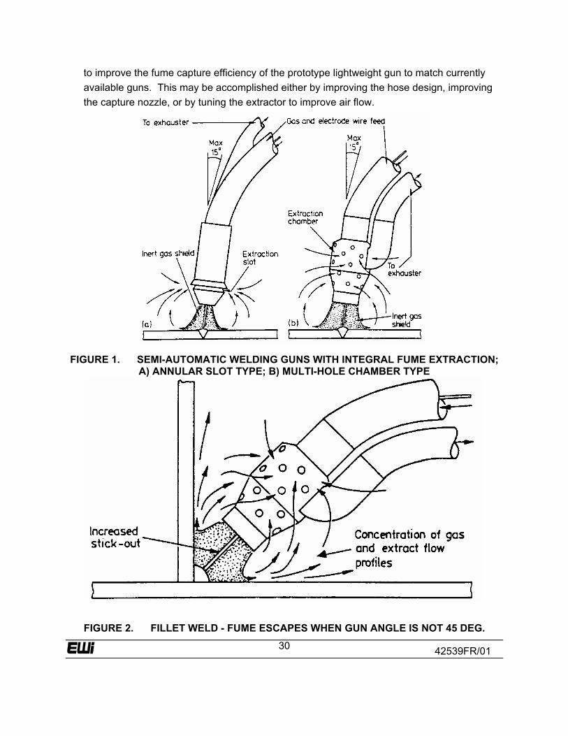
3.0 Literature Review Literature on fume extracting welding guns was collected and reviewed in relation to design, application, efficiency of extraction, and potential effects on gas shielding and weld quality. The search was conducted in the Weldasearch and Metadex databases using Cambridge Scientific Abstracts. The abstracts generated by this search were retrieved and 53 papers and publications were reviewed in detail. 3.1 Basic Principles of Welding Fume Extraction Guns Manual GMAW or FCAW welding guns are normally held so the angle of the electrode with respect to the work is between about 15 and 45 degrees. This allows the operator to see the arc and forming weld bead and gas flow is directed over the elongated weld pool. The nozzle to work distance will generally be 5/8 inch to 1inch (16 to 25 mm), but this may be as low as ¼ inch (6 mm) or as high as 1¼ inch. (30mm) for access to difficult fillet welds. The rate of flow of shielding gas for these arc welding processes is generally in the range of 25 ft3/hr to 45 ft3/hr (12 to 21L/min.) The intention is that the gas flow should be a continuous non-turbulent (i.e., laminar) stream surrounding the arc column. Incorrect gas flow, either too high or too low, will cause inclusions of oxides and nitrides and porosity in the weld metal. Two basic types of exhaust nozzles are common for fume extraction welding guns. Both types of nozzles are concentric with the gun head to promote uniform extraction characteristics in all welding positions. In the first type (Figure 1a) extraction is via an annular exhaust slot or bell shaped skirt located about ½ inch. (12mm) behind the gas nozzle. In the second type (Figure 1b) an extraction chamber is used, having a number of small holes distributed over the surface, spreading the suction zone over a greater area. Both arrangements can be designed as an integral part of the standard semi-automatic welding gun, but the exhaust chamber type is probably more adaptable to fitting as an addition to existing equipment. Exhaust flow rates are not very great, ranging from about 35-60 cubic feet per minute (CFM) (1.0 to 1.7m3/min) according to type and design. Extraction hoses that carry fumes away from the gun are typically between 1 inch and 1½ inch (25 to 38 mm) inside diameter. The vacuum fan or blower used to draw air through the nozzle must provide the required flow at a static pressure which may be 50 to 80 inch of water (12 to 20 kPa) measured at the gun. The concept of “on-gun” exhaust is a highly desirable means of ensuring the most efficient capture of weld fume at the source. However, the feasibility of the method, although well suited to the semi-automatic welding gun, is unfortunately restricted in the case of the gas shielded
42539FR/01
3
system by the local environment created by the welding process itself. In this case, the introduction of fume extraction close to the weld zone must satisfy conflicting requirements. On one hand, the downward flow of shielding gas must be non-turbulent, on the other, an upward and inward flow of hot fume must be drawn back into the gun head by the exhaust system. The balance that must be struck between these opposing forces to ensure maximum extraction efficiency without loss of weld quality because of reduced or disturbed gas flow is in practice very fine. Furthermore, this balance must be maintained under conditions where miniaturization and low extraction volumes accentuate the characteristically rapid decrease in suction velocity with increasing distance from an exhaust opening. Under such circumstances, small variations of the gun attitude in relation to the work can make substantial differences to the flow profiles of gas and extract air. 3.2 Early Development of Fume Extracting Guns Fume extracting guns were developed concurrently by several companies in North America and Europe in the late 1960’s and early 1970’s. Wildenthaler and Cary(2) describe the development of an add-on nozzle to remove fumes. Assessment of the efficiency of capture was done by photographing the fume removal. More detail was provided by Wiehe, Cary, and Wildenthaler(3), of a system that uses an outward tapering cone around the gas nozzle. A regenerative blower rated at 35 CFM (1.0 m3/min) at 80 inch of water (20 kPa) was used to provide the extraction. Breathing zone measurements were made for individual elements, and a reduction was seen in all cases, up to an estimated 85% efficiency. Kollman(4) describes the development of a fume extracting gun in his 1973 paper. A range of pumps was considered, including vane, centrifugal blower and a regenerative pump. In order to minimize size, a 1 hp (0.75 kJ/s) centrifugal blower pump was chosen. This unit developed 97 inch water (24 kPA) pressure drop at zero flow (dead-ended), with a working range of 32 to 40 CFM (0.9 to 1.1 m3/min) air flow at a pressure of 53 to 71 inch of water (13 to 18 kPa). Kollman notes that the pump must be a bypass type, since use of exhausted air to cool the motor will quickly lead to accumulation of iron oxide within the motor, leading to early failure. Kollman experimented with several designs of fume nozzles and eventually used a hybrid design with a flared annular skirt and a series of peripheral holes. In addition, holes were provided in the flow line that could be blocked or left open by the welder to regulate the extraction air flow. Kollman found that lower flow rates were required when welding in a deep V-groove or when welding a filet into a corner, in order to avoid disturbing the gas stream. Two articles in 1972(5) (6) describe the development of a fume extracting gun. Fumes are extracted by a lightweight chamber that fits over the standard gas nozzle, about ¾ inch (19 mm) above the nozzle outlet, and extracts 60 CFM (1.7 m3/min). The fume extraction is said not to
42539FR/01
4
interfere with the efficiency of the gas shield and not to interfere with the operator’s view. It is also claimed that the additional cooling that is provided by the extracted air permits higher welding currents without raising handle temperatures. Welding Design and fabrication(7) describes 5 smoke extracting guns available from various manufacturers. It is claimed that gas mixtures containing over 10% helium do not work well with a smoke exhaust system, stating that gas inertia is low as it leaves the feed line, and tends to be sucked up by the smoke extraction nozzle before it gets to the workpiece. 3.3 Operation of Fume Extracting Guns Head(8) described the factors affecting the operation of fume extracting guns in detail. There is a fine balance of the conflicting shielding/extraction flow profiles. From the literature describing these systems it is clear that the work being welded is important to the balance by turning the downward flowing gas into the upward/inward flowing extracted air. Similarly, it is recommended that the welding gun be used as far as possible perpendicular to the work, or no more than a few degrees from perpendicular, thus preserving some degree of symmetry in the somewhat concentrated conditions. In practice, the joint configuration and position will vary these conditions considerably, for example:
• Flat Butt Weld (Figure 1) – the configuration for which the equipment is designed; good control likely.
• Fillet Weld (Figure 2) – the position of the components being welded has a
concentrating effect on gas and extract flows, increasing velocity; fume control generally satisfactory, unless gun angle deviates from a line bisecting the weld. Difficult access may require increased electrode stickout, increasing the distance between the extractor and arc and thus moving away from optimum control conditions.
• Confined Box Section – the conflicting forces of gas flow and extract flow act in a
complex and unpredictable manner. Fume may swirl away out of the capture zone, possibly dispersed by the concentrated gas flow, but control may also be good because of concentrated extraction flow paths.
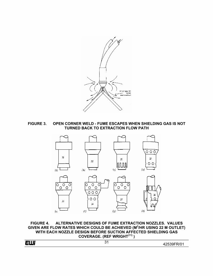
• Open Corner Weld (Figure 3) –the shielding gas is not turned back to the
extraction flow path; fume escapes the control zone.
• Vertical Weld – the axis of the gun head is horizontal, and the vertical rise of the plume of weld fume through thermal lift exceeds the capture condition; fume capture may be poor.
42539FR/01
5
• Welding Complex Assemblies – gun angle may be dictated by the relative positions of work and the need to retain the arc within the vision of the operator. With excessive deviation from the most favorable gun attitude, the balance may be altered as described and fume control lost.
• Operator Fatigue – gun angle may drop from the perpendicular because of
fatigue. Welding methods, aids, manipulators, etc. should be introduced to compensate where possible.
3.3.1 Gas Flow and Electrode Stickout Shielding gas flow is normally in the region of 25 to 45 ft3/hr (12 to 21 L/min). Some manufacturers recommend a slight increase when using fume extraction guns (e.g., to at least 45 ft3/hr (21 L/min). In some cases operators experienced poor weld quality with fume extraction guns and promptly increased gas flow to compensate. Excessive increases in gas flow will destroy the system balance, blowing the fume from the capture zone. The effect of independent variation of gas flow has been observed in a series of tests(8). A simple fillet weld giving long runs was selected, the components being at 90 degrees to each other and positioned on a manipulator so as to be symmetrical about the vertical axis. This gave a good open joint position for flat welding, with satisfactory gun angle. In this example the optimum gas flow was found to be about 55 ft3/hr (26 L/min), slightly high, but possibly attributable to increased exhaust velocities created by the fillet weld geometry. It should be added that satisfactory welds have been seen at gas flow rates as low as 34 ft3/hr (16 L/min). The nozzle to work distance is important to the system balance, in that it determines the distance between the arc (fume source) and the exhaust opening. If this distance is too great, fume may escape the limited envelope of the exhaust capture zone aided by gas flow and heat. Equally, if it is too small the gas shielding may be affected, with the temptation to increase gas flow and consequences as described. The optimum nozzle to work distance appears to be between ¾ inch and 1 inch (19 to 25 mm). 3.3.2 Exhaust Conditions The critical nature of the shielding gas/extraction flow balance precludes the possibility of designing into the system exhaust flow to compensate for any fall in performance during use. As already noted, the nature of the apparatus is such that an exhauster is required to maintain
42539FR/01
6
the flow volume against substantial resistance. There are a number of important factors to be borne in mind to ensure that there is no unacceptable loss of extraction flow: (a) Where particulate filters are in use, these should not be allowed to become clogged to
the point where airflow is unacceptably reduced. A “filter clogged” indicator is recommended. Installation for direct discharge to the outside atmosphere is an advantage in this respect. Exhaust volumes usually will be small enough not to be of concern as regards to heat conservation, certainly as compared with volumes discharged by general workshop ventilation.
(b) Periodic checking of the performance of the exhaust system is recommended.
Thorough examination requires special knowledge and instrumentation, but a useful check is simply to take the static pressure (vacuum) in the suction hose at the welding gun connection. It is important to know the correct figure, which can be established at the time of commissioning the system, and the minimum acceptable suction. A simple way of measuring suction is to use a vacuum gauge adapted to accept a hypodermic needle, which can be inserted through the wall of the rubber hose at any desired location.
(c) During surveys, more than one hybrid system was seen (i.e., a combination of
unmatched exhauster and ventilated welding gun). The probability is that such hybrid systems will be ineffective. For example, the single annular slot type exhaust system requires only about 35 CFM (1.0 m3/min ) extraction volume at approximately 8 inch of water (2 kPa) vacuum whereas the multi-hole chamber type may take up to 60 CFM (1.7 m3/min) at 60 inch of water (15 kPa) vacuum. Each type of extraction hood is designed to operate over a limited flow range and mismatching either in terms of flow volume or vacuum (insufficient vacuum can result in low extraction volume) can give a serious shortfall in performance.
3.4 Evaluating Gun Extraction Efficiency Four principal methods of evaluating the efficiency of fume extracting guns have been developed:
1. Use of photography to make a qualitative evaluation of efficiency. This method was used by early workers and is still employed in marketing literature to graphically illustrate the effect of fume extract guns.
2. Total fume collection. In this technique, the total fume emitted is collected, first with the
extraction system turned on, then with the extraction system turned off. This technique is relatively simple and perhaps the most accurate method of measuring gun efficiency in extracting fumes.
3. Breathing zone measurements. Standard techniques for measuring the fume in the
welders breathing zone are used, with and without operation of the fume extraction
42539FR/01
7
system. This method has the advantage that it directly measures the quantity of most interest, the fume exposure of the welder. However, breathing zone measurements tend to be subject to large variations due to the size and position of welder, general environment, and position of weldment.
4. Tracer techniques. Use of a tracer gas such as helium has been employed in order to
make continuous measurements. This method requires a mass spectrometer to measure the tracer gas.
Aastrup(9) used a system similar to the standard AWS total fume collection system to measure the efficiency of fume extraction guns. He measured a 96.5% reduction in fume using a fume extraction gun compared to welding with the same conditions without extraction. His experiments were conducted with 0.062 in. (1.6 mm) diameter flux cored electrodes, using 100%CO2 shielding gas and welding on mild steel in the flat position.
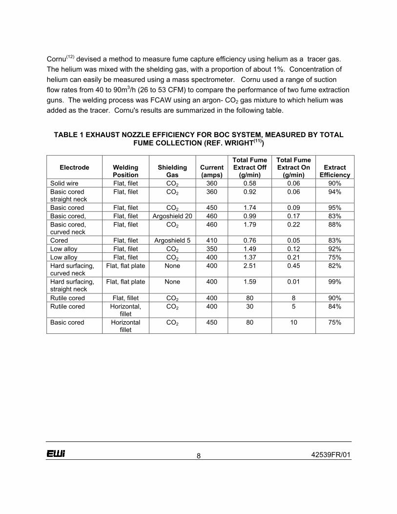
Wangenen(10) studied several aspects of welding fume, including the use of fume extraction guns. The model tested had a finger activated trigger which permitted quick shifting of normal suction flow of 45 to 50 ft3/hr (21 to 24 L/min) down to 35 ft3/hr (17 L/min). It is claimed that, since at least a 1:1 ratio of shielding gas flow to suction flow is required for weld quality, the normal shielding gas flow of 30 to 35 ft3/hr (14 to 17 L/min) had to be increased to 50 to 55 ft3/hr (24 to 26 L/min). While these flows maintained quality in flat position welding, satisfactory welds in angles and shapes required reducing suction flow to 35 ft3/hr (17 L/min) while maintaining shielding gas flow at 50 ft3/hr (24 L/min). When welding with 0.062-in (1.6 mm) diameter wire (quoted as “E70S-1B"), at 200 in./min (85 mm/s), and 98%Ar2%O2, the overall reduction in the welder’s breathing zone fume was 78%. It was reported that the smoke exhaust gun appeared to provide a major improvement in fume control on flat surface welding, but was less successful when suction flow had to be reduced from 50 to 35 ft3/hr (24 to 17 L/min) for welding in angle sections and corners. Wangenen concluded that that the fume exhaust gun is the most practical and effective means of local exhaust ventilation for welding of galvanized or stainless steels. Wright(11) describes development of a fume extracting nozzle that could be used with different guns. The nozzle is coaxial with the gun and a variety of nozzle designs were evaluated (Figure 4). A design with an inward tapering nozzle with both slots and holes and an outlet diameter of 7/8 inch (22) mm was eventually selected (Figure 4(h)). A pump with a maximum extraction rate of 35CFM (1.0 m3/min) was used, with a 9 ft (2.8 m) extraction hose. Wright tested this system both by taking breathing zone measurements and by measuring fume not collected by the extract torch. Overall, the extraction nozzle removed 90% of fumes. Fairly consistent results were obtained both from total fume and breathing zone measurements. The results are summarized as follows:
42539FR/01
8
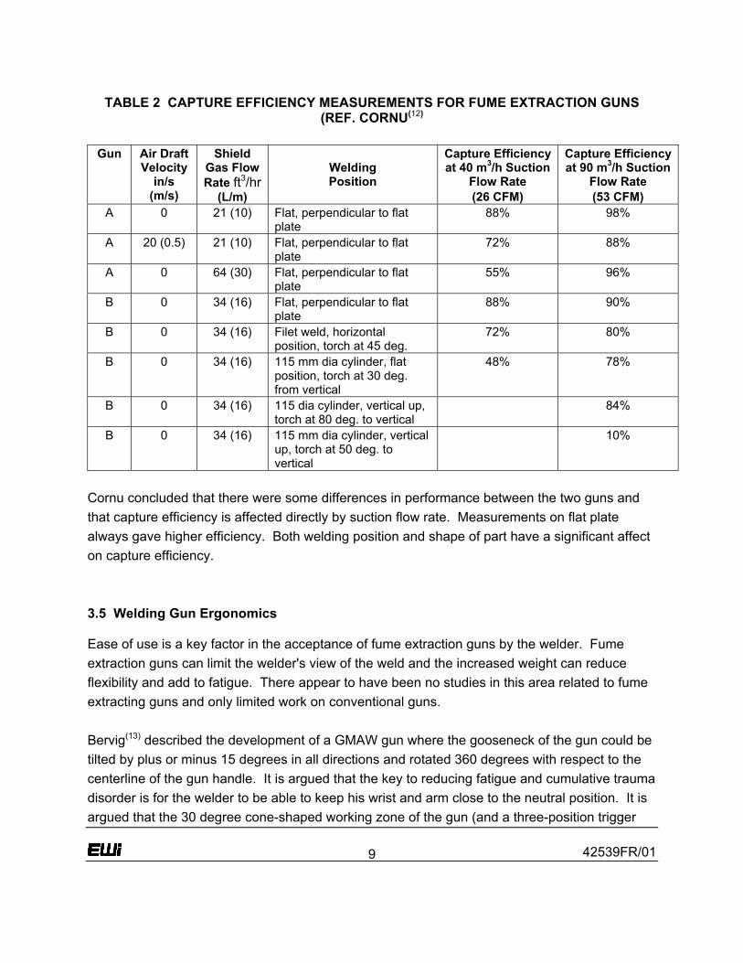
Cornu(12) devised a method to measure fume capture efficiency using helium as a tracer gas. The helium was mixed with the shelding gas, with a proportion of about 1%. Concentration of helium can easily be measured using a mass spectrometer. Cornu used a range of suction flow rates from 40 to 90m3/h (26 to 53 CFM) to compare the performance of two fume extraction guns. The welding process was FCAW using an argon- CO2 gas mixture to which helium was added as the tracer. Cornu's results are summarized in the following table.
TABLE 1 EXHAUST NOZZLE EFFICIENCY FOR BOC SYSTEM, MEASURED BY TOTAL FUME COLLECTION (REF. WRIGHT(11))
Electrode
Welding Position
Shielding
Gas
Current(amps)
Total Fume Extract Off
(g/min)
Total Fume Extract On
(g/min)
Extract
Efficiency Solid wire Flat, filet CO2 360 0.58 0.06 90% Basic cored straight neck
Flat, filet CO2 360 0.92 0.06 94%
Basic cored Flat, filet CO2 450 1.74 0.09 95% Basic cored, Flat, filet Argoshield 20 460 0.99 0.17 83% Basic cored, curved neck
Flat, filet CO2 460 1.79 0.22 88%
Cored Flat, filet Argoshield 5 410 0.76 0.05 83% Low alloy Flat, filet CO2 350 1.49 0.12 92% Low alloy Flat, filet CO2 400 1.37 0.21 75% Hard surfacing, curved neck
Flat, flat plate None 400 2.51 0.45 82%
Hard surfacing, straight neck
Flat, flat plate None 400 1.59 0.01 99%
Rutile cored Flat, fillet CO2 400 80 8 90% Rutile cored Horizontal,
fillet CO2 400 30 5 84%
Basic cored Horizontal fillet
CO2 450 80 10 75%
42539FR/01
9
TABLE 2 CAPTURE EFFICIENCY MEASUREMENTS FOR FUME EXTRACTION GUNS (REF. CORNU(12)
Gun Air Draft
Velocity in/s
(m/s)
Shield Gas Flow Rate ft3/hr
(L/m)
Welding Position
Capture Efficiency at 40 m3/h Suction
Flow Rate (26 CFM)
Capture Efficiency at 90 m3/h Suction
Flow Rate (53 CFM)
A 0 21 (10) Flat, perpendicular to flat plate
88% 98%
A 20 (0.5) 21 (10) Flat, perpendicular to flat plate
72% 88%
A 0 64 (30) Flat, perpendicular to flat plate
55% 96%
B 0 34 (16) Flat, perpendicular to flat plate
88% 90%
B 0 34 (16) Filet weld, horizontal position, torch at 45 deg.
72% 80%
B 0 34 (16) 115 mm dia cylinder, flat position, torch at 30 deg. from vertical
48% 78%
B 0 34 (16) 115 dia cylinder, vertical up, torch at 80 deg. to vertical
84%
B 0 34 (16) 115 mm dia cylinder, vertical up, torch at 50 deg. to vertical
10%
Cornu concluded that there were some differences in performance between the two guns and that capture efficiency is affected directly by suction flow rate. Measurements on flat plate always gave higher efficiency. Both welding position and shape of part have a significant affect on capture efficiency. 3.5 Welding Gun Ergonomics Ease of use is a key factor in the acceptance of fume extraction guns by the welder. Fume extraction guns can limit the welder's view of the weld and the increased weight can reduce flexibility and add to fatigue. There appear to have been no studies in this area related to fume extracting guns and only limited work on conventional guns. Bervig(13) described the development of a GMAW gun where the gooseneck of the gun could be tilted by plus or minus 15 degrees in all directions and rotated 360 degrees with respect to the centerline of the gun handle. It is argued that the key to reducing fatigue and cumulative trauma disorder is for the welder to be able to keep his wrist and arm close to the neutral position. It is argued that the 30 degree cone-shaped working zone of the gun (and a three-position trigger
42539FR/01
10
handle design) enable more difficult welds to be accomplished with the welder working in or close to the neutral position, thus reducing stress on the welders muscle’s and ligaments. Bruss(14) describes the modification of a standard gun to improve usability. It is stated that tool weights in excess of 5 pounds (2.3 kg) supported by the arm held away from the body would produce fatigue in the small muscles in the forearm and shoulder. This article also states that most guns fall within the 5 pound (2.3 kg) range and are relatively close in weight between manufacturers. Bruss recommends that the diameter for tools with a wraparound grip should be between 1 inch and 1.75 inch (25 to 44 mm), with the optimum dimension being 1.25 inch (32 mm). These studies also indicate that the length of the tool handle should be sufficient to distribute the forces on either side of the palm and across digits two and five, requiring the palm force-bearing area to be at least 3.5 inch (90 mm) long. It is also suggested that moving the trigger to the top or side of the gun improves the welder’s ability to position themself to the side of the gun so that they can see the weld more clearly. Bruss changed the gooseneck design of 45 to 60 degrees to 35 to 40 degrees arguing that this allowed a more natural position of the arm and also removed the need for stain relief at the back of the gun. Tregaskiss(15) describes the results of a study on ergonomic gun design with the intent of determining whether a correlation exists between the physical characteristics of a gun and the amount of muscle action required to operate it. The general ergonomic criteria for evaluation of hand tools, adapted to welding were:
• The weight of the gun • The grip circumference • The force needed to activate the trigger • The rotational torque - the force required to twist the gun and cable through 180
degrees. • The shape and surface texture of the handle • The ability of the handle to absorb vibration.
Six standard ergonomic factors and physical criteria were evaluated in use of the guns:
• Static muscle loading • Hand/arm positioning • Pressure on tissues or joints • Vibration • Pinch points • Versatility for left or right handed operation.
42539FR/01
11
Electromyography (EMG) electrodes were used to measure muscle activation. Four welders were involved in the tests, and these welders also assessed their preference for each gun. Detailed data are given for dynamic (EMG) tests, and static data on the torches. In general there was good correlation between this data, and the welders preference. That is, the light, flexible guns created less muscle strain and were much preferred by the welders over the heavier, less flexible guns. 3.6 Commercial Equipment Cullison(16) indicated that major redesign efforts have decreased the size and weight from the early models and reduced operator fatigue by making the handle smaller and more comfortable to use. There have been some efforts to make the exhausting hose more flexible and in some instances lighter weight by going to thinner but higher quality material. Although there appears to be no standard among manufacturers, vacuum efficiency is typically retained with a minimum flow rate of 70 CFM (2 m3/min) as measured at the extraction nozzle. 3.7 Application Experience There is little literature on industrial applications of fume extraction guns. Most descriptions are by commercial suppliers of equipment and then often describing the user or multi-user systems with central vacuum systems, rather than the small pumps which can be used with just one torch. Welding Design and Fabrication(17) report on the installation of a central exhaust system together with fume extraction guns. The central exhaust system uses 6 to 8 inch (150 to 200 mm) diameter spiral duct for the main head, with 3 inch (75 mm) diameter drops that terminate with air distributor valves. The central unit runs at 1910 CFM (54 m3/min) with 26 vertical drop lines each providing 20 to 60 CFM (0.55 to 1.7 m3/min) fume gun suction. Manning(18) describes air-cooled, maneuverable, lightweight fume extraction guns with a control vent that varies the flow. Fume reduction of by up to 97% is claimed. Oke(20) provides a brief description of a on-gun extractor system. Pumphrey(21) compares flow rates, typically 80 to 100 CFM (2.3 to 2.8 m3/min) for suction nozzles, attached by magnets to the workpiece and 35 to 60 CFM (1.0 to 1.7 m3/min) for integrated fume extraction guns. The reduced need for make-up air is noted, where a low vacuum system for twenty stations would require an air flow rate of 12000 CFM (340 m3/min), a high vacuum system requires an airflow rate of 1200 CFM (34 m3/min). The high vacuum level,
42539FR/01
12
40 to 70 inch of water (10 to 17 kPa), permits the use of hoses up to 25 ft (8 m) long with 1.5 inch (38 mm) diameter. Rasmussen(22) describes the installation of high vacuum systems in shipyards. A major advantage of the high vacuum system in this application is the ability to use small and often very long extraction hoses. A vacuum of 80 inch water (20 kPa) is required. In this application, the most commonly used extraction equipment is either a small suction nozzle with a magnet base, or a GMAW fume extraction gun connected to a small flexible hose of 2 or 1¾ inch (50 or 45 mm). The advantage of these small hoses is that the equipment is light, and can be taken into small working areas. The airflow is 117 CFM (3.3 m3/min) using nozzles, and 58 CFM (1.7 m3/min) using torches with integrated extraction. Stuart & Bervig patent(23) describes a gun with articulated nozzle and integrated fume extraction. Svetsaren(24) gives a brief description of high vacuum systems for robot welding, using small nozzles attached to the gun. With the nozzle 1½ to 2 inch (40 to 50) mm from the point of welding, and 1½ to 2 inch (38 to 50) mm hoses, efficiencies of 75 to 90% are claimed.
4.0 Summary of Fume Extraction Gun Experience in U.S. Shipyards
A telephone survey was conducted of eight U.S. shipyards, with very similar comments from all the engineers who provided information. None of the yards are currently using fume extraction guns and the reasons given are the same in all cases: current guns are much too heavy and inflexible. In addition, the need in many cases to use a fume extraction pump within 15 feet of the fume extraction gun also made the practical application of the fume gun extraction systems very difficult. It is clear from the comments received that fume extraction guns will have to be significantly lighter and more flexible to be accepted in shipyards, and that methods will have to be found either to eliminate a fume extraction pump close to the welder, (possibly by utilizing a central high vacuum system); or the portable fume extraction pumps would also have to be much smaller and lighter weight. Many of the yards had the opinion that fume extraction guns would need to approach conventional guns in size and weight. Engineers also noted that trials or demonstrations of fume extraction guns had led to porosity in welds, and that extraction efficiency varied widely, being fairly good in the flat position, and less effective in the vertical position. It appears from this survey that yards are meeting current fume concentration requirements using local exhaust ventilation where necessary. However, several of the yards indicated that they would be interested in using fume extraction guns if they could be made to meet the requirements of reduced size and weight.
42539FR/01
13
5.0 Evaluation of Current Fume Extraction Guns
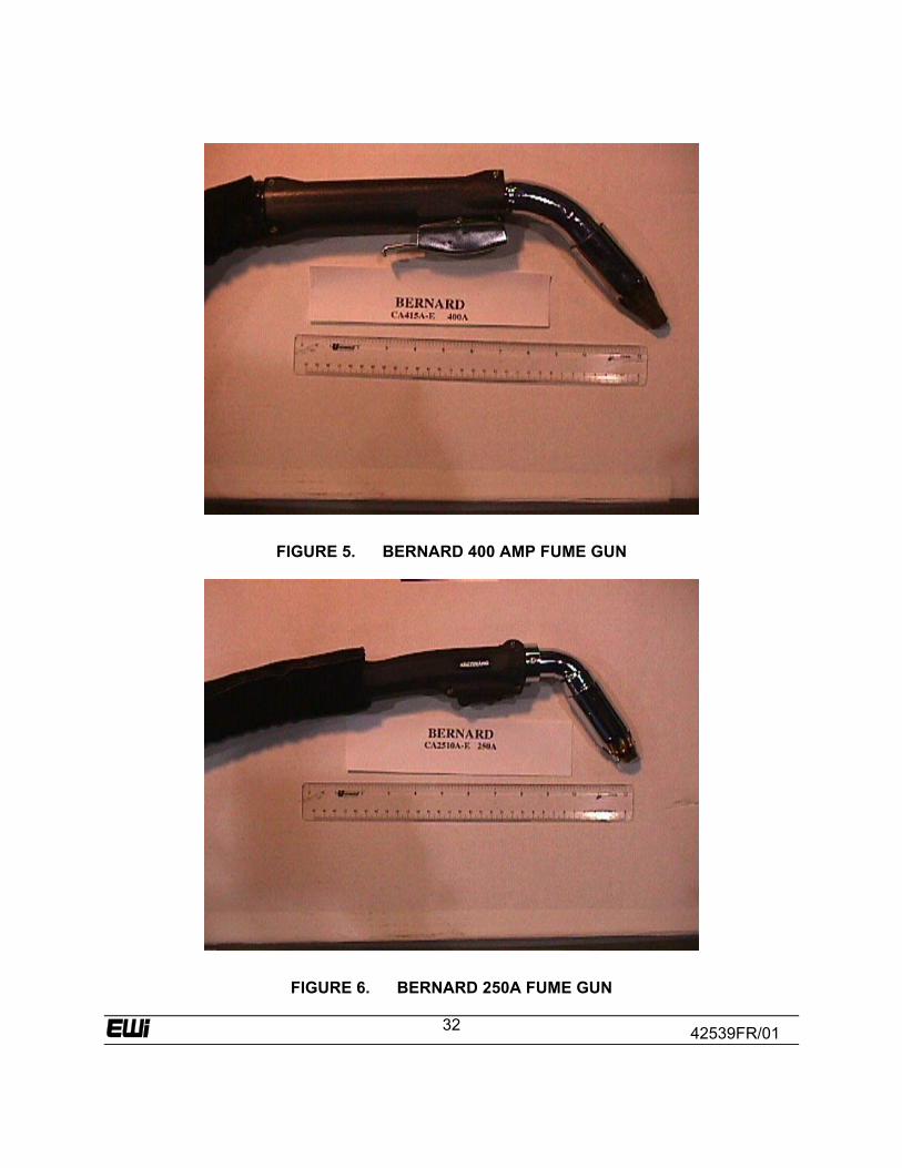
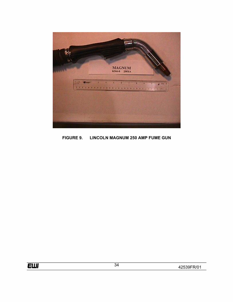
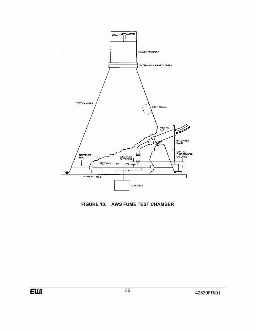
5.1 Measurement of Fume Extraction Efficiency Five fume extraction guns were obtained from three manufacturers for evaluation. These guns are shown in Figures 5 through 9. These fume extraction guns were evaluated by welders for usability and compared to five conventional guns for a range of ergonomic factors. Three of the fume extraction guns also were evaluated for fume extraction efficiency. The literature describes several methods that have been used measure fume extraction efficiency, including photography, breathing zone measurements, use of tracer gases, and measurement of total fume. Photography does not provide a quantitative result and the tracer gas method requires special equipment for sampling the tracer. Breathing zone measurements directly monitor the welder’s breathing zone, but are subject to a high level of variability. The technique adopted for this study was the measurement of total fume using the standard AWS fume generation rate test(25) Chamber shown in Figure 10. This system uses forced air flow to direct welding fume through a filter where it is collected. This method is widely used by other researchers and gives reproducible results. The test chamber is calibrated by making welds, at 24, 26, and 28 arc volts. The measured results should be within 10% of the published standard calibration values to confirm that the fume chamber is operating correctly. The conical test chamber is constructed so that the welding gun may be positioned to weld in the flat position. An air gap of 0.5 to 0.75 inch is maintained between the base of the chamber and the surface on which it rests. A standard glass fiber filter, 12-inch diameter and approximately 0.5-inch thick is used. Welding fume is drawn through the filter by an air pump capable of sampling at a rate of 25 to 35 ft3/hr with a filter pressure differential of 3 to 5 inch of water. The filter is placed in an oven set between 93 and 107ºC. The filters are removed from the oven and weighed prior to starting the fume test. Immediately after the test the filter is weighed again. The amount of fume captured in the filter is equal to the difference in weight of the filter before and after the test. Dividing the fume collected by the welding time gives the fume generation rate (FGR) in grams per minute (gm/min). The weld is deposited as a bead-on-plate weld, using 12-inch square, 0.5-inch thick A36 plate. The test is normally performed under standard welding conditions, as follows:
• ER70S-3, 0.045-in. wire • 100 % CO2 Shielding Gas

42539FR/01
14
• DC electrode positive, with a constant potential power source • ¾-inch contact tip-to-work distance • 14 in/min travel speed. • Welding Parameters: Wire feed speed 300 in/min (approximately 225 amps and
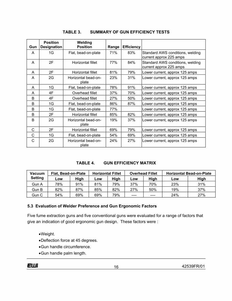
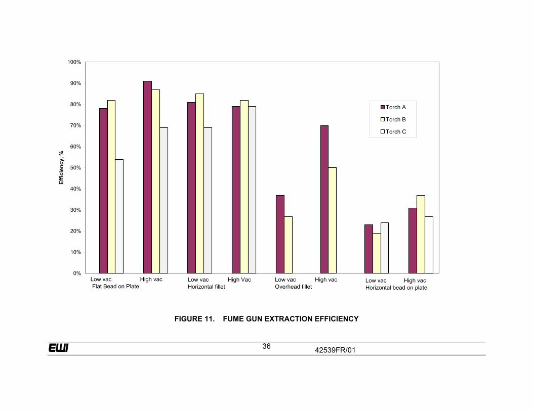
26 volts) The fume generation rate of the process was measured using each of the three fume extraction guns tested with no vacuum flow to establish the baseline FGR. Then each gun was tested using the low setting of the fume extractor and finally using the high setting on the fume extractor. The vacuum pump used for the tests with all three guns had two settings, low and high, and with a maximum rating of 50 CFM at 60-inch water gauge. It is known that the performance of fume extraction guns depends strongly on welding position. The AWS chamber test was modified slightly to determine the effect of welding position. The standard AWS flat position test was performed as usual on the surface of the plate. A 4-inch diameter, 4-inch tall by 3/8-inch thick tube was tacked on the 12-inch square plate. A horizontal fillet weld was made between the plate and the tube, and an overhead fillet weld was made by turning the specimen upside down. Finally, a horizontal bead-on-plate weld could be made on the cylindrical surface of the tube. This welding position simulated vertical welding. One series of test welds were made at the standard AWS welding conditions (wire feed speed 300 in/min approximately 225 amps and 26 volts). These parameters produce a weld bead size that is too large for the out-of-position tests so the parameters were reduced until the current was approximately 125 amps. These parameters were maintained for all subsequent tests. Three tests were performed for each combination of welding gun, welding position, and vacuum setting and the results averaged to obtain the fume generation rate. It is apparent from comparing the tests that no significant changes in gun capture efficiency can be attributed to the change of current. 5.2 Results of Fume Extraction Efficiency Tests The results of the fume extraction gun capture efficiency tests are shown in Table 3, Table 4, and in Figure 11. The efficiency of capture of the fume extraction gun is defined as:
42539FR/01
15
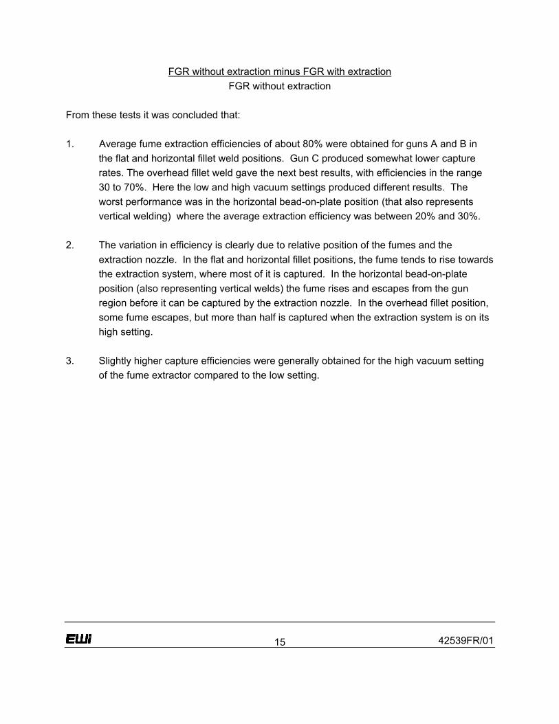
FGR without extraction minus FGR with extraction FGR without extraction
From these tests it was concluded that: 1. Average fume extraction efficiencies of about 80% were obtained for guns A and B in
the flat and horizontal fillet weld positions. Gun C produced somewhat lower capture rates. The overhead fillet weld gave the next best results, with efficiencies in the range 30 to 70%. Here the low and high vacuum settings produced different results. The worst performance was in the horizontal bead-on-plate position (that also represents vertical welding) where the average extraction efficiency was between 20% and 30%.
2. The variation in efficiency is clearly due to relative position of the fumes and the extraction nozzle. In the flat and horizontal fillet positions, the fume tends to rise towards the extraction system, where most of it is captured. In the horizontal bead-on-plate position (also representing vertical welds) the fume rises and escapes from the gun region before it can be captured by the extraction nozzle. In the overhead fillet position, some fume escapes, but more than half is captured when the extraction system is on its high setting.
3. Slightly higher capture efficiencies were generally obtained for the high vacuum setting
of the fume extractor compared to the low setting.
42539FR/01
16
TABLE 3. SUMMARY OF GUN EFFICIENCY TESTS
Gun
Position Designation
Welding Position
Range
Efficiency
A 1G Flat, bead-on-plate 71% 83% Standard AWS conditions, welding current approx 225 amps
A 2F Horizontal fillet 77% 84% Standard AWS conditions, welding current approx 225 amps
A 2F Horizontal fillet 81% 79% Lower current, approx 125 amps A 2G Horizontal bead-on-
plate 23% 31% Lower current, approx 125 amps
A 1G Flat, bead-on-plate 78% 91% Lower current, approx 125 amps A 4F Overhead fillet 37% 70% Lower current, approx 125 amps B 4F Overhead fillet 27% 50% Lower current, approx 125 amps B 1G Flat, bead-on-plate 86% 87% Lower current, approx 125 amps B 1G Flat, bead-on-plate 77% Lower current, approx 125 amps B 2F Horizontal fillet 85% 82% Lower current, approx 125 amps B 2G Horizontal bead-on-
plate 19% 37% Lower current, approx 125 amps
C 2F Horizontal fillet 69% 79% Lower current, approx 125 amps C 1G Flat, bead-on-plate 54% 69% Lower current, approx 125 amps C 2G Horizontal bead-on-
plate 24% 27% Lower current, approx 125 amps
TABLE 4. GUN EFFICIENCY MATRIX
Flat, Bead-on-Plate Horizontal Fillet Overhead Fillet Horizontal Bead-on-Plate Vacuum Setting Low High Low High Low High Low High Gun A 78% 91% 81% 79% 37% 70% 23% 31% Gun B 82% 87% 85% 82% 27% 50% 19% 37% Gun C 54% 69% 69% 79% ---- ---- 24% 27%
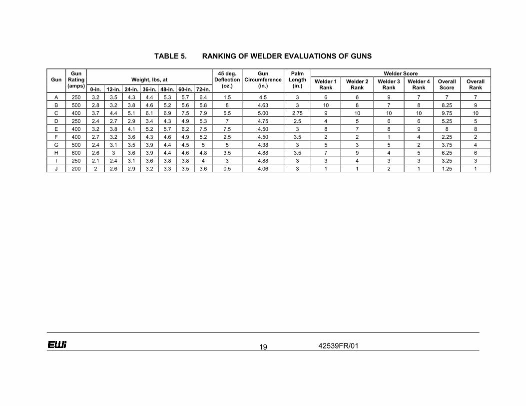
5.3 Evaluation of Welder Preference and Gun Ergonomic Factors Five fume extraction guns and five conventional guns were evaluated for a range of factors that give an indication of good ergonomic gun design. These factors were : •Weight. •Deflection force at 45 degrees. •Gun handle circumference. •Gun handle palm length.
42539FR/01
17
In addition, 4 welders were asked to rank each of the 10 guns based on these factors and provide comments on whether they liked or disliked each gun. Gun weight is not a well-defined value since the welder is carrying both the gun itself and part of the cable assembly. In order to estimate gun weight, each gun was suspended at the center of the palm area, where the welders 3rd finger would touch the gun, with the cable assembly lying in a straight line along the ground behind the gun. The gun was then elevated using a digital scale until the gun gas nozzle just left the ground. This gives a measure of the weight of the gun together with small part of the cable assembly. The weight of the gun was then measured using the digital scale as the gun was elevated to 1 foot and then 2 through 6 feet. The weight on just leaving the ground (weight at 0-inch) and the weight at 5 feet (weight at 60-inch) were used in later comparisons. The gun was next suspended at 4 feet and the force necessary to deflect the gun in a horizontal plane through 45 degrees was measured. This gives some indication of the stiffness or flexibility of the gun assembly. The circumference of the gun handle was measured and the length of the handle in the palm area was estimated. The results of these measurements are shown in Table 5. Four welders were asked to rank the guns based on user preference. Each welder did pairwise comparisons of each gun until they had placed the guns in order of their preference. The welders were asked to ignore gun type and current rating in their evaluations. The welders also were asked to ignore gun trigger pressure, even though they all considered this to be an important factor in ease of use. In fact, the welders considered that locking triggers were much to be preferred, since they considered that this significantly reduced strain and allowed for some repositioning of the hand while welding. The rankings given by the welders were averaged to generate an overall score for each gun, so that the best possible score would be 1.0 and the worst 10.0. It is apparent from Table 5 that the welders were in general agreement on gun ranking. For instance, 3 out of 4 welders ranked gun J as number 1, and 3 out of 4 ranked gun C as number 10. 5.4 Results of Welder Preference and Gun Ergonomic Factor Evaluations The overall welder scores of gun performance were plotted against gun weight, 45 degree deflection force, and handle circumference. Figure 12 shows a plot of gun weight at 60 inch height versus welder score. It is not unexpected that the welders prefer the lighter weight guns to the heavy guns. However, it is rather surprising that such good agreement was obtained,
42539FR/01
18
with the plotted values lying close to a straight line. With only one exception, the fume extraction guns were rated lower than any of the conventional guns. A similar picture is apparent from the plot of gun weight at 0-inch versus welder score (Figure 13). Again good agreement is obtained. It is interesting to note that the one fume gun which was rated as better than one of the conventional guns was in fact lighter than two of the conventional guns in weight at 0-inch and was close to the weight of three conventional guns in weight at 60-inch. A plot of welder score versus 45 degree defection force (Figure 14) again shows a general trend between welder score and low force, although with some quite large scatter in the data. Some of the fume guns had swivel connections or flexible bellows connections that helped reduce the 45 degree deflection force. Figure 15 shows the plot of handle circumference versus welder score, again with a general trend of agreement between welder score and handle circumference.
42539FR/01
19
TABLE 5. RANKING OF WELDER EVALUATIONS OF GUNS
Welder Score Weight, lbs, at
Gun
Gun Rating (amps) 0-in. 12-in. 24-in. 36-in. 48-in. 60-in. 72-in.
45 deg.Deflection
(oz.)
Gun Circumference
(in.)
Palm Length
(in.) Welder 1
Rank Welder 2
Rank Welder 3
Rank Welder 4
Rank OverallScore
Overall Rank
A 250 3.2 3.5 4.3 4.4 5.3 5.7 6.4 1.5 4.5 3 6 6 9 7 7 7 B 500 2.8 3.2 3.8 4.6 5.2 5.6 5.8 8 4.63 3 10 8 7 8 8.25 9 C 400 3.7 4.4 5.1 6.1 6.9 7.5 7.9 5.5 5.00 2.75 9 10 10 10 9.75 10 D 250 2.4 2.7 2.9 3.4 4.3 4.9 5.3 7 4.75 2.5 4 5 6 6 5.25 5 E 400 3.2 3.8 4.1 5.2 5.7 6.2 7.5 7.5 4.50 3 8 7 8 9 8 8 F 400 2.7 3.2 3.6 4.3 4.6 4.9 5.2 2.5 4.50 3.5 2 2 1 4 2.25 2 G 500 2.4 3.1 3.5 3.9 4.4 4.5 5 5 4.38 3 5 3 5 2 3.75 4 H 600 2.6 3 3.6 3.9 4.4 4.6 4.8 3.5 4.88 3.5 7 9 4 5 6.25 6 I 250 2.1 2.4 3.1 3.6 3.8 3.8 4 3 4.88 3 3 4 3 3 3.25 3 J 200 2 2.6 2.9 3.2 3.3 3.5 3.6 0.5 4.06 3 1 1 2 1 1.25 1
42539FR/01
20
The guns with higher current ratings are, in general, heavier, stiffer, and bulkier than the guns with low current ratings. Figure 16 illustrates this point, where welder score is plotted against current rating. Here the conventional guns fall into one group, receiving higher scores as they become heavier and the fume extraction guns fall into a second group, since in general they are heavier than the conventional guns. Apart from stating some of the obvious relationships between welder preference and gun ergonomic parameters, the value of this exercise is in providing quantitative values as guidelines for the design of lightweight fume extraction guns. In the survey previously completed, shipyards expressed the view that fume guns would have to be significantly lighter than current designs to be acceptable for practical use. It was therefore concluded that a reasonable target (design guideline) for gun weight would be 4 pounds at 60 inch suspension, and 2 pounds at 0 inch. This will of course be easier to achieve for the 250 amp rating gun than for the 400 amp rating. However, the highest rated fume extraction gun is not very far from these requirements, with a weight of 4.9 pounds at 60 inch and 2.4 pounds at 0 inch. A suitable target for flexibility would be 2 ounces for 45 degree deflection. One of the fume guns is already below this level at 1.5 ounces. Finally, smaller gun handles were preferred by the welders. The best rated gun handle had a circumference of 4.06 inch. A suitable target for this parameter is 4.4 inch. Two of the fume extraction guns were already close to this target at 4.5 inch.
6.0 Lightweight Fume Extraction Gun Design Targets
The results of measurements of fume extraction efficiency showed that fume guns are capable of providing effective extraction of welding fumes in the flat position and for horizontal position fillet welds, with extraction efficiencies in the range of 80% or better. Results in the overhead fillet position were also quite good, ranging between 30 and 70%. However, in the horizontal bead-on-plate position, considered to be representative of vertical welding, extraction efficiencies were lower at about 30%. Good correlation was obtained between welder preference and gun ergonomic factors, and a series of design guidelines or targets were generated: * Maximum gun weight at 60 inch should be 4 pounds * Maximum gun weight at 0 inch should be 2 pounds * 45 degree deflection force should be less than 2 ounces * Maximum gun handle circumference should be 4.4 inch
42539FR/01
21
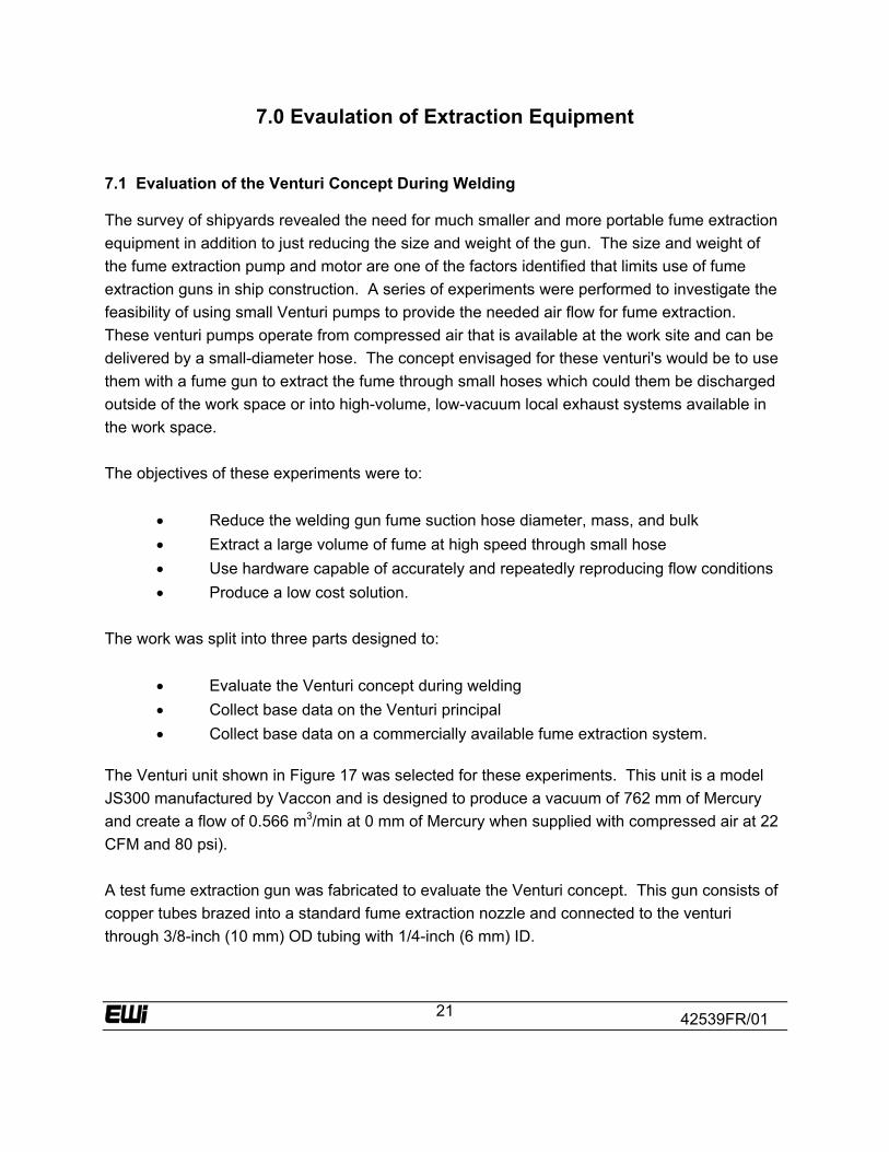
7.0 Evaulation of Extraction Equipment 7.1 Evaluation of the Venturi Concept During Welding The survey of shipyards revealed the need for much smaller and more portable fume extraction equipment in addition to just reducing the size and weight of the gun. The size and weight of the fume extraction pump and motor are one of the factors identified that limits use of fume extraction guns in ship construction. A series of experiments were performed to investigate the feasibility of using small Venturi pumps to provide the needed air flow for fume extraction. These venturi pumps operate from compressed air that is available at the work site and can be delivered by a small-diameter hose. The concept envisaged for these venturi's would be to use them with a fume gun to extract the fume through small hoses which could them be discharged outside of the work space or into high-volume, low-vacuum local exhaust systems available in the work space. The objectives of these experiments were to:
• Reduce the welding gun fume suction hose diameter, mass, and bulk • Extract a large volume of fume at high speed through small hose • Use hardware capable of accurately and repeatedly reproducing flow conditions • Produce a low cost solution.
The work was split into three parts designed to:
• Evaluate the Venturi concept during welding • Collect base data on the Venturi principal • Collect base data on a commercially available fume extraction system.
The Venturi unit shown in Figure 17 was selected for these experiments. This unit is a model JS300 manufactured by Vaccon and is designed to produce a vacuum of 762 mm of Mercury and create a flow of 0.566 m3/min at 0 mm of Mercury when supplied with compressed air at 22 CFM and 80 psi). A test fume extraction gun was fabricated to evaluate the Venturi concept. This gun consists of copper tubes brazed into a standard fume extraction nozzle and connected to the venturi through 3/8-inch (10 mm) OD tubing with 1/4-inch (6 mm) ID.
42539FR/01
22
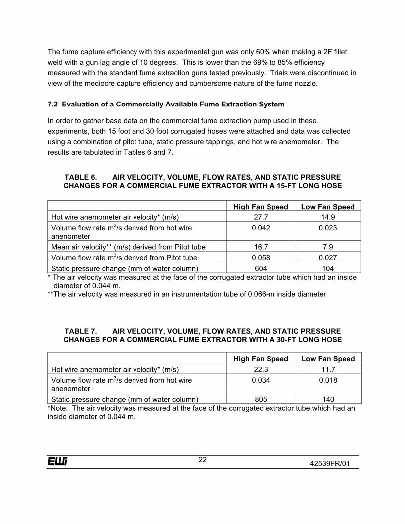
The fume capture efficiency with this experimental gun was only 60% when making a 2F fillet weld with a gun lag angle of 10 degrees. This is lower than the 69% to 85% efficiency measured with the standard fume extraction guns tested previously. Trials were discontinued in view of the mediocre capture efficiency and cumbersome nature of the fume nozzle. 7.2 Evaluation of a Commercially Available Fume Extraction System In order to gather base data on the commercial fume extraction pump used in these experiments, both 15 foot and 30 foot corrugated hoses were attached and data was collected using a combination of pitot tube, static pressure tappings, and hot wire anemometer. The results are tabulated in Tables 6 and 7.
TABLE 6. AIR VELOCITY, VOLUME, FLOW RATES, AND STATIC PRESSURE CHANGES FOR A COMMERCIAL FUME EXTRACTOR WITH A 15-FT LONG HOSE
High Fan Speed Low Fan Speed Hot wire anemometer air velocity* (m/s) 27.7 14.9 Volume flow rate m3/s derived from hot wire anenometer
0.042 0.023
Mean air velocity** (m/s) derived from Pitot tube 16.7 7.9 Volume flow rate m3/s derived from Pitot tube 0.058 0.027 Static pressure change (mm of water column) 604 104
* The air velocity was measured at the face of the corrugated extractor tube which had an inside diameter of 0.044 m.
**The air velocity was measured in an instrumentation tube of 0.066-m inside diameter
TABLE 7. AIR VELOCITY, VOLUME, FLOW RATES, AND STATIC PRESSURE CHANGES FOR A COMMERCIAL FUME EXTRACTOR WITH A 30-FT LONG HOSE
High Fan Speed Low Fan Speed Hot wire anemometer air velocity* (m/s) 22.3 11.7 Volume flow rate m3/s derived from hot wire anenometer
0.034 0.018
Static pressure change (mm of water column) 805 140 *Note: The air velocity was measured at the face of the corrugated extractor tube which had an inside diameter of 0.044 m.

42539FR/01
23
8.0 - Evaluation of Prototype Gun
The preceding sections of this report developed guidelines for a lightweight fume extraction welding gun that would have features that will better meet the operating requirements of shipbuilders and of other US industries as well. The targets for weight and manipulative force detailed in the previously referenced reports were: • Maximum gun weight at 60 inch should be 4 pounds. • Maximum gun weight at 0 inch should be 2 pounds. • 45 degree deflection force should be less than 2 ounces. • Maximum gun handle circumference should be 4.4 inch. These design guidelines were made available to gun manufacturers participating in this project. One manufacturer developed a prototype "new lightweight" fume extraction gun for evaluation. This gun is designated "Gun K." 8.1 Comparison of Lightweight and conventional guns The new prototype lightweight fume extraction gun "K" was found to have the following features: • Gun weight at 60 inch was 4 lb. 2 oz. • Gun weight at 0 inch was 2 lb. 4 oz. • 45 degree deflection force was 1.9 ounces. • Gun handle circumference was 4.5 inch. • Rating was 250 Amps with Argon/CO2 shielding gas
TABLE 8. COMPARISON OF LIGHTWEIGHT GUN WITH DESIGN TARGETS AND STANDARD FUME EXTRACTION GUNS
Gun Gun
Rating (amps) Weight in pounds at 0-inch
Weight in pounds
at 60-inch
45 deg. Deflection
(ounce)
Gun Circumference
(inch)
Palm Length (inch)
Design Targets
250 2.0 4.0 2 4.4 -
A 250 3.2 5.7 1.5 4.5 3 B 500 2.8 5.6 8 4.63 3 C 400 3.7 7.5 5.5 5.00 2.75 D 250 2.4 4.9 7 4.75 2.5 E 400 3.2 6.2 7.5 4.50 3
New Lightweight Gun K
250 2.2 4.1 1.9 4.50 3
42539FR/01
24
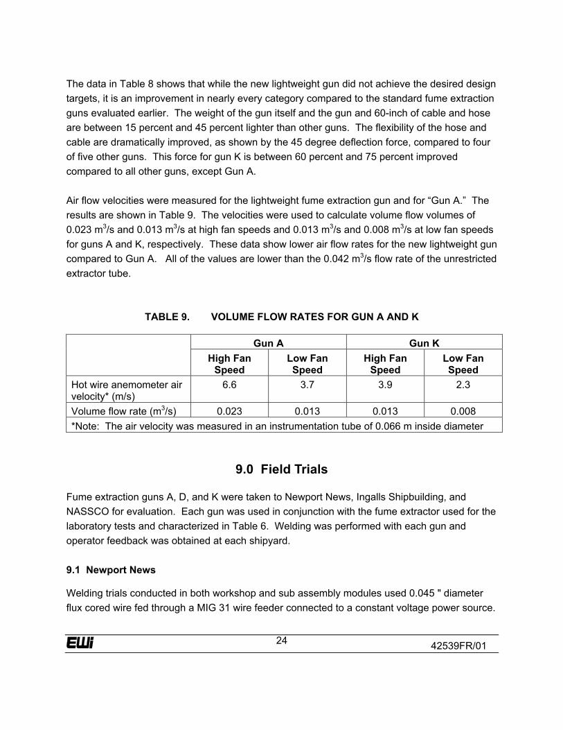
The data in Table 8 shows that while the new lightweight gun did not achieve the desired design targets, it is an improvement in nearly every category compared to the standard fume extraction guns evaluated earlier. The weight of the gun itself and the gun and 60-inch of cable and hose are between 15 percent and 45 percent lighter than other guns. The flexibility of the hose and cable are dramatically improved, as shown by the 45 degree deflection force, compared to four of five other guns. This force for gun K is between 60 percent and 75 percent improved compared to all other guns, except Gun A. Air flow velocities were measured for the lightweight fume extraction gun and for “Gun A.” The results are shown in Table 9. The velocities were used to calculate volume flow volumes of 0.023 m3/s and 0.013 m3/s at high fan speeds and 0.013 m3/s and 0.008 m3/s at low fan speeds for guns A and K, respectively. These data show lower air flow rates for the new lightweight gun compared to Gun A. All of the values are lower than the 0.042 m3/s flow rate of the unrestricted extractor tube.
TABLE 9. VOLUME FLOW RATES FOR GUN A AND K
Gun A Gun K High Fan
Speed Low Fan Speed
High Fan Speed
Low Fan Speed
Hot wire anemometer air velocity* (m/s)
6.6 3.7 3.9 2.3
Volume flow rate (m3/s) 0.023 0.013 0.013 0.008 *Note: The air velocity was measured in an instrumentation tube of 0.066 m inside diameter
9.0 Field Trials Fume extraction guns A, D, and K were taken to Newport News, Ingalls Shipbuilding, and NASSCO for evaluation. Each gun was used in conjunction with the fume extractor used for the laboratory tests and characterized in Table 6. Welding was performed with each gun and operator feedback was obtained at each shipyard. 9.1 Newport News Welding trials conducted in both workshop and sub assembly modules used 0.045 " diameter flux cored wire fed through a MIG 31 wire feeder connected to a constant voltage power source.
42539FR/01
25
The shielding gas used was 75%Ar/25%CO2. The following observations and results were noted: Gun A: Initially, nearly 100% of fume was captured when using Gun A for a 2F fillet weld.
Fracture of the joint revealed root porosity. Subsequent discussion revealed the use of 0 degree gun lag-angle by the welder who was attempting to capture all of the fume by adapting his normal technique. The lag angle was increased to a standard 10 degrees and the porosity was eliminated. Another fillet weld was made in the 3F position. Sixty to seventy percent of the fume was captured and the fracture test was successful. Notably, most of the escaping fume was kept away from the welder’s vision.
Gun K: A slightly smaller proportion of fume was extracted with Gun K and 2F fillet
welds, although it was noted that occasionally 100% was captured. The fracture tests showed the welds to be sound.
Additional welding trials were conducted in a semi-confined area within a production module. The weld joints selected were all located between stiffeners and bulkheads or bulkheads and decks. No individual weld made was longer than 18 inch. The welders were relatively well positioned on staging to improve access and joint visibility. Results can be summarized as follows:
Gun A: The immediate reaction of welders who switched to Gun A was “it’s heavier.”
This was tempered by the subsequent observation “but they are all heavy.” Fume capture in the flat (1F) fillet position was good and capture appeared to be 100% for the 4F fillet. Only a percentage of fume was captured on the 3F fillet. The raised edge gun trigger was considered easy to find. Gas cup visibility was noted as good. The slip ring at the base of the gun was also noted as good and no significant tightness was observed with 180 deg. of rotation.
Gun K: This gun was connected, the umbilical stretched out, and a natural resonance
noted in the flexible bellows before an arc was struck. Repositioning of the umbilical cured the resonance. The welders liked the gun, but recognized that they were used to a different manufacturer’s gun and would therefore take a little time to adapt. Visible fume was kept out of the welder’s breathing zone
Gun fume capture performance can be summarized as follows:
42539FR/01
26
• All of the fume was captured for a 3F fillet weld. • Most of the fume was captured for a 4F fillet weld with an inverted gun., • Most of the fume was captured for a 2F fillet weld.
The shipyard presently uses a variety of conventional (non-fume extraction) guns for different applications. Some welders prefer long-neck guns to allow them to position themselves farther from the heat of the arc and preheat. Welder’s comments on the usability of the fume extraction guns can be summarized as follows:
Gun A was judged to have good flexibility, although the weight of this gun was judged to be
heavier when compared with Gun K. Both Gun A and K were felt to be a little smaller in diameter than the presently used 400
amp production guns. The principal of on-gun fume extraction was good as it kept most of the smoke out of the
welding vision and improved visibility in the weld area. Gun D was heavy, possibly as a result of the protective leather sleeve. The gun itself was
“OK” with a good swivel, but increased flexibility was necessary in the umbilical. Gun K was rated as having good balance and good “back weight.” A possible lack of
visibility of the welding arc may occur in 1-inch butt welds; a smaller diameter gas diffuser may help. The gun trigger was thought to be well designed. These welders are used to locking triggers.
The guns and cable assemblies need further testing for durability against dropping and weld spatter. Cables and hoses should have self-extinguishing properties.
A smaller, more efficient extractor would be nice, but it was recognized that there would be significant design issues and decisions required on operating strategies. The welders did not believe extractor mass is a problem when balanced against wire feed mass.
9.2 Ingalls Shipbuilding The guns and extractor were examined in a development workshop, but unfortunately without welding due to the lack of the proper connectors for the wire feeder that was available. The production team all felt that the guns were heavy, but noted that Gun K had good flexibility. The extractor was thought to be too large and too heavy. These welders currently use the small 8-inch diameter wire spools which are relatively lightweight. 9.3 NASSCO The trials were conducted on butt welds and fillet welds on-board a landing ship in the fan space in an area close to the deckhead. Welding was done using 0.045-inch diameter flux cored
42539FR/01
27
electrode and CO2 shielding gas. The butt welds were made onto ceramic backing with an 8-mm root gap. The welder was positioned on staging and had to reach upwards a little to access the joints. Welding trials of the fume extraction guns can be summarized as follows: Gun A: This gun was viewed as being heavier. Fume capture was as follows:
Between 50 % and 60% of the fume was captured welding the root pass of a 3G butt weld onto ceramic backing. Capture increases to 90% as the deckhead was approached.
Fume capture was judged to be between 30% and 40% when welding the root pass in a 1G flange butt weld on a 24-inch deep Tee stiffener. Some fume was jetted through the mousehole in the web of the stiffenenr.
Good fume clearance was accomplished during welding of a 4F fillet between 1-inch thick plate and the stiffener web.
Gun K: The gun was viewed as comfortable. The following statements show the capture
efficiency: Approximately 40% of the fume was captured welding the root pass in a 3G butt joint
onto ceramic backing. Fume capture was judged to be poor welding the root pass in a 1G flange butt weld
on a 24-inch deep Tee stiffener. Most of the fume was jetted through the mousehole in the stiffener web.
Only about 20% of the fume was captured when welding a 4F fillet between a 1-inch thick plate and the stiffener web.
An estimated 20% of the fume was captured welding a 1G butt joint. The welder was able to tell when the fume extraction was switched on and off, but did not believe there was any significant improvement in overall visibility of the weld area. It was suggested that the fume capture cup from Gun A be tested on the lighter Gun K. Following the trials the welder stated that his preferred extraction method was to use an “elephant's trunk” connected to the global fume extraction system as opposed to an on-gun nozzle and local extractor. His reasoning was due to a number of factors which included relative height between the access staging and the weld joint, his stature, mass and bulk of both welding guns, (particularly Gun A) and the ambient temperature.
42539FR/01
28
9.4 Summary of Shipyard Trials Examination of the data for Gun K shows that it met or nearly met all of the design targets for weight and flexibility. It is, however, apparent from the practical welding trials that fume capture efficiency was not as effective with this gun as with Gun A. This is believed to be due to the smaller extraction hose resulting in lower air flow rates through the gun. This smaller hose was part of the lighter weight requirement for this gun. The data implies that there were higher pressure losses within the gun assembly for Gun K compared to Gun A given that the extraction fan was a constant throughout. It would therefore seem logical to re-test Gun K using a higher capacity extractor in order to determine which inlet nozzle is the most efficient. The welding trials at the shipyard also show how the use of a different shielding gas, joint detail and welding technique can substantially change the flow pattern of fume and hence effect the capture efficiency.
10.0 Conclusion The objective of this project was to develop a lightweight, cooler fume extraction welding gun for GMAW and FCAW welding and to incorporate ergonomic engineering to improve usability. The project gathered past experience with fume extraction welding guns, evaluated current guns, developed a prototype lightweight gun, and evaluated this gun during shipyard trials. The results of this work lead to the following conclusions: 1. Published literature reveals that fume extraction welding guns have been available since
the early 1970's.
• The concept of "on-gun" fume extraction is highly desirable since the point of capture is very close to the source of fume. Fume extraction guns also involve relatively low air flow rates compared to other local fume capture methods.
• Depending on the application, fume extraction efficiencies as high as 98% have been reported for welding in the flat, horizontal fillet, and overhead welding positions. Capture efficiency can be as low as 20% in the vertical and horizontal groove welding positions.
• The increased weight, larger size, and limited flexibility of fume extraction guns are the important factors that have limited their use.
2. A survey of U.S. shipyards concluded that there is a need to reduce the size and weight
while improving the flexibility of fume extraction guns in order to make them more acceptable for widespread use. The ruggedness of the gun and the portability of the
42539FR/01
29
fume extraction equipment are also key factors to acceptance and use of this type of equipment in a shipyard.
3. The performance of five fume extraction guns was evaluated during this project.
• Fume extraction efficiency measurements show these guns are capable of capturing more than 80% of fumes in the flat, horizontal-fillet, and overhead welding positions. However, capture efficiency drops substantially in the horizontal groove and vertical welding positions.
• Welders compared the fume extraction guns to conventional guns on the basis of size, weight, and flexibility. These evaluations confirmed that lightweight and good flexibility are most important "user features" for welding guns.
4. The following design targets for an improved lightweight fume-extracting gun were
established based on the shipyard survey and the evaluation of current guns: • Maximum gun weight at 60 inch should be 4 pounds. • Maximum gun weight at 0 inch should be 2 pounds. • 45 degree deflection force should be less than 2 ounces. • Maximum gun handle circumference should be 4.4 inch. • Gun should have a minimum rating of 250 amps, 100% duty cycle with Argon/CO2
shielding gas.
5. A prototype lightweight fume extraction gun was developed and evaluated in the laboratory and at three shipyards. These evaluations showed: • Although the new lightweight gun did not achieve all of the desired design targets, it is
an improvement in nearly every category compared to the standard fume extraction guns evaluated. The weight of the gun itself and the gun and 60-inch of cable and hose are between 15 percent and 45 percent lighter than other guns. The flexibility of the hose and cable are dramatically improved, as shown by the 45 degree deflection force, compared to four of five other guns.
• Shipyard user trials show the welders preferred the prototype lightweight gun to the other guns tested on the basis of ergonomic factors. These trials also show that the fume capture efficiency of the prototype lightweight gun was not as good as conventional fume extraction guns. Poor capture efficiency may be due to the small diameter hose used to help reduce weight and improve flexibility of this gun. Alternatively, the fume extractor may not have been suitable for this gun design.
6. This project showed that improvements can be made to reduce the weight and improve the
flexibility of lightweight fume extraction guns. However, additional refinements are needed
42539FR/01
30
to improve the fume capture efficiency of the prototype lightweight gun to match currently available guns. This may be accomplished either by improving the hose design, improving the capture nozzle, or by tuning the extractor to improve air flow.
FIGURE 1. SEMI-AUTOMATIC WELDING GUNS WITH INTEGRAL FUME EXTRACTION; A) ANNULAR SLOT TYPE; B) MULTI-HOLE CHAMBER TYPE
FIGURE 2. FILLET WELD - FUME ESCAPES WHEN GUN ANGLE IS NOT 45 DEG.
42539FR/01
31
FIGURE 3. OPEN CORNER WELD - FUME ESCAPES WHEN SHIELDING GAS IS NOT TURNED BACK TO EXTRACTION FLOW PATH
FIGURE 4. ALTERNATIVE DESIGNS OF FUME EXTRACTION NOZZLES. VALUES GIVEN ARE FLOW RATES WHICH COULD BE ACHIEVED (M3/HR USING 22 M OUTLET)
WITH EACH NOZZLE DESIGN BEFORE SUCTION AFFECTED SHIELDING GAS COVERAGE. (REF WRIGHT(11) )
42539FR/01
32
FIGURE 5. BERNARD 400 AMP FUME GUN
FIGURE 6. BERNARD 250A FUME GUN

42539FR/01
33
FIGURE 7. BINZEL 500 AMP FUME GUN
FIGURE 8. LINCOLN MAGNUM 400 AM FUME GUN
42539FR/01
34
FIGURE 9. LINCOLN MAGNUM 250 AMP FUME GUN
42539FR/01
35
FIGURE 10. AWS FUME TEST CHAMBER
42539FR/01
36
0%
10%
20%
30%
40%
50%
60%
70%
80%
90%
100%Ef
ficie
ncy,
%
Torch A
Torch B
Torch C
Low vac High vac Flat Bead on Plate
Low vac High VacHorizontal fillet
Low vac High vacOverhead fillet
Low vac High vacHorizontal bead on plate
FIGURE 11. FUME GUN EXTRACTION EFFICIENCY
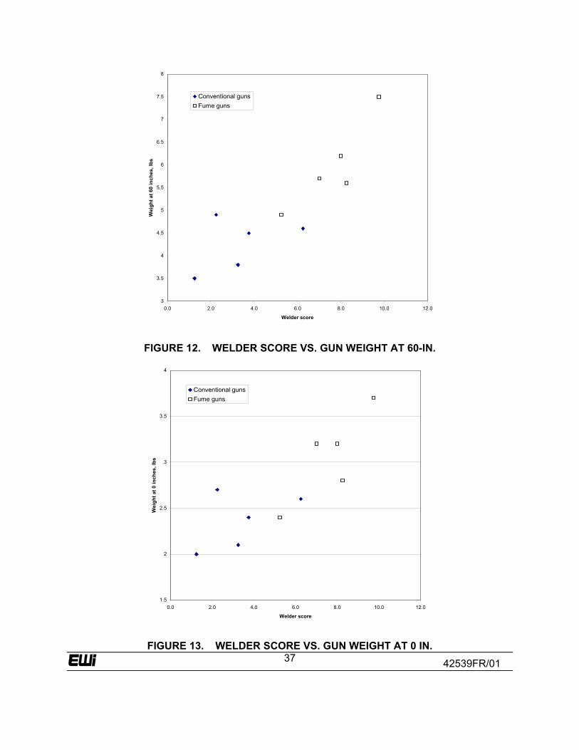
42539FR/01
37
3
3.5
4
4.5
5
5.5
6
6.5
7
7.5
8
0.0 2.0 4.0 6.0 8.0 10.0 12.0
Welder score
Wei
ght a
t 60
inch
es, l
bs
Conventional gunsFume guns
FIGURE 12. WELDER SCORE VS. GUN WEIGHT AT 60-IN.
1.5
2
2.5
3
3.5
4
0.0 2.0 4.0 6.0 8.0 10.0 12.0
Welder score
Wei
ght a
t 0 in
ches
, lbs
Conventional gunsFume guns
FIGURE 13. WELDER SCORE VS. GUN WEIGHT AT 0 IN.

42539FR/01
38
0
1
2
3
4
5
6
7
8
9
0.0 2.0 4.0 6.0 8.0 10.0 12.0
Welder score
Forc
e (o
z) fo
r 45
degr
ee d
elec
tion
Conventional gunsFume guns
FIGURE 14. WELDER SCORE VS. 45 DEG. DEFLECTION FORCE
4
4.2
4.4
4.6
4.8
5
5.2
0.0 2.0 4.0 6.0 8.0 10.0 12.0
Welder score
Torc
h C
ircum
fere
nce,
inch
es
Conventional gunsFume guns
FIGURE 15. WELDER SCORE VS. HANDLE CIRCUMFERENCE
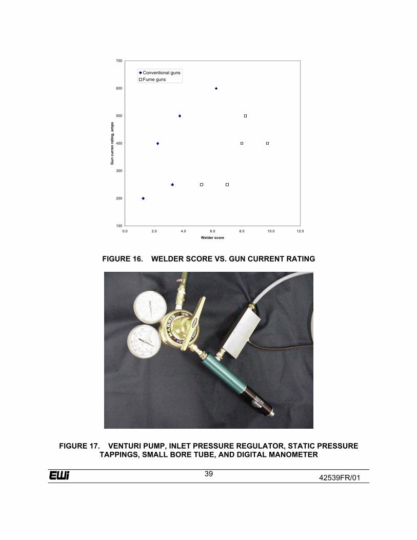
42539FR/01
39
100
200
300
400
500
600
700
0.0 2.0 4.0 6.0 8.0 10.0 12.0
Welder score
Gun
cur
ren
ratin
g, a
mps
Conventional gunsFume guns
FIGURE 16. WELDER SCORE VS. GUN CURRENT RATING
FIGURE 17. VENTURI PUMP, INLET PRESSURE REGULATOR, STATIC PRESSURE TAPPINGS, SMALL BORE TUBE, AND DIGITAL MANOMETER
42539FR/01
40
11.0 References 1. NSRP 0463: Impact of Recent and Anticipated Changes in Airborne Emission Exposure
Limits on Shipyard Workers; Navy Joining Center and a Navy/Industry Task Group March 1996.
2. Wildenthaler, L. and Cary, H.B., "A progress report on fume extracting system for gas
metal arc welding unit", Welding Journal, September 1971, pp. 623-635. 3. Wiehe, A.E., Cary, H., and Wildenthaler, L., "Application of a smoke extracting system
for continuous electrode welding", Welding Journal, June 1974, pp. 349-361. 4. Kollman, K.G., "Solving the problem of GMAW fume extraction", Welding Journal,
August 1973, pp. 504-508. 5. "Welding Gun also Extracts Smoke", Canadian Welder and Fabricator May 1972, pp. 32-
33. 6. “The GMA Smoke Extracting Gun”, Welding Journal, June 1972, pp. 419-420. 7. "Smoke Guns: Exhausting Welding Smoke at the Source," Welding Design and
Fabrication, May 1975, pp. 47-51. 8. Head, I.W., "Integral fume extraction in MIG/CO2 welding", Metal Construction,
December 1979, pp. 633-638. 9. Aastrup, P., "Influence of MIG-gun fume extraction systems on concentration of welding
fume, concentration of ozone and optical radiation", Danish Welding Institute Report (Svejsecentralen) 30.1.78. Contribution to GSP 5510. The Welding Institute, Doc. No. 5510/29
10. Wangenen, H.D.V., “Assessment of selected control techniques for welding fumes”,
NIOSH report no 79-125, January 1979 11. Wright, R.R., Fume removal for semi-automatic welding", pp 109-117 in “International
Conference on Exploiting Welding in Production Technology, The Welding Institute, London, April 1975.
12. Cornu, J.C., Muller, J.P., and Guelin, J.C., "A method for measuring the capture
efficiency of fume-extracting welding guns", Welding in the World/Soudage dans le Monde, Vol. 31, No. 1, Jan-Feb 1993, pp. 49-53.
13. Bervig D., "MIG [metal inert gas welding] gun designed to eliminate repetitive motion
injuries", Fabricator, Vol. 22, No. 9, Nov. 1992, pp. 44-45. 14. Bruss, R.A., "Designing GMA welding guns with the welder’s comfort in mind", Welding
Journal, October 1996, pp. 31-33.
42539FR/01
41
15. Tregaskiss, J. and Dutta, S.P., "Understanding the ergonomics of MIG gun design", The Fabricator, November 1993, pp. 16-19.
16. Cullison, A., "Take a look at fume extracting welding guns", Welding Journal, September
1994, pp. 35-37. 17. "Fume extractor guns clean the air", Welding Design and Fabrication , February 1995,
pp. 26-27. 18. Manning, S., "Fume extraction - MIG VAC’S air cooled smoke gun", Canadian Welder
and Fabricator, Nov-Dec 1990, pp. 17-19. 19. Nyback, A., Vanska, P., Gustavsson, J., and Heino, S., "Investment in multi-purpose,
high-vacuum extraction system at Kvaerner Masa-Yards shipyard in Turku, Finland", Svetsaren, 51(3), 1996, pp. 34-37.
20. Oke S. and Middleton, P., "Fume control - what are the options", Australasian Welding
Journal, Second Quarter 1995, pp. 12-14. 21. Pumphrey, T., "Arc welding fume control", Welding Design and Fabrication, February
1999, pp. 48-52.
22. Rasmussen, J.E., "High vacuum extraction of welding fumes within the shipbuilding Industry", Svetsaren, Vol. 48, No. 2, 1994, pp. 19-21.
23. Stuart, K.H. and Bervig, D.R., "Welding gun assembly", U.S. patent 5,491,321, Feb 13,
1996. 24. Svetsaren, "Extracting fumes from robot welding", 1996, 34. 25. AWS Standard F1.2:1999, “Laboratory Method for Measuring Fume Generation Rates
and Total Fume Emission of Welding and Allied Processes”.