A New Type of Hybrid Semi-Active Control Strategy in the ...

Development of Hybrid Floor Isolation System
with Semi-active Control
Y. Shi & R. Enokida Kyoto University, Japan
E. Sato E-Defense, National Research Institute for Earth Science and Disaster Prevention, Japan
M. Nakashima DPRI, Kyoto University, Japan
SUMMARY
The floor isolation system is designed for one floor of the structure. Limited by the space, relatively small
seismic clearance is preferred. However, the long period type input motion will cause large displacement and
even pounding. To design a floor isolation system which works effectively under both short and long period
motions, the semi-active technology is employed. This paper presents the shaking table test results of a
semi-active controlled floor isolation system equipped with a MR damper. The LQR control algorithm is used to
calculate the desired force and a PI force tracking scheme is designed to track the design force. A new method is
proposed to update the control gain based on the frequency components of the input motion. The test results
show that the semi-active controlled floor isolation system can effectively reduce the acceleration while
maintaining the displacement in an acceptable level.
Keywords: hybrid floor isolation system, semi-active control, shaking table test
1. INTRODUCTION
Base isolation is one of the most successful and widely-applied techniques of mitigating structural
vibration during earthquakes. It is also designed to protect the important equipment so as to maintain
the functionality of the structure during and immediately after the earthquake (for example, Sato et al.
2011). However, the base isolation technique applied to the entire building may not be practical in
some cases, including those for retrofit. In such a situation, the floor isolation system (FIS) that is
designed for one floor of the structure is a cost-effective alternative. The isolation system with passive
damping is found not necessarily optimal for a wide band of frequencies and intensities of the input
motions (Nagrajaiah and Sun 2000). Semi-active control is another alternative to augment the control
force. Recent research proves that a semi-active controlled base isolation system performs better than
an equivalent passive controlled system (Yoshioka et al. 2002).
This paper experimentally investigated a semi-active controlled hybrid floor isolation system (HFIS)
employing a MR fluid damper for the protection of contents inside of the room. A series of
preliminary tests were performed to examine the dynamic behavior of the MR damper. Next, a PI
controller was built to calculate the command current corresponding to the design forces obtained
from a LQR controller. A series of shaking table tests were performed using the control strategy
proposed. Passive control was also tested for comparison with the semi-active control.
2. INVERSE DYNAMIC MODEL OF MR DAMPER
A MR damper is essentially a nonlinear device, and it is widely used in semi-active control. To
develop control algorithms that take the maximum advantage of the unique features of the MR damper,
a model must be established to describe the relationship between the input current and the output force.
In real applications, the output force is the known parameter calculated from the adopted control
algorithm, and the input current is unknown. Various kinds of models have been developed to model
the characteristics of MR dampers (Wang and Liao 2011). However, the inverse dynamic model for
MR dampers, which calculates the current based on the desired force, is still immature. The dynamic
model, such as the phenomenological model (Spencer et al. 1997), can effectively emulate the
dynamic behavior of the MR damper. Due to its complexity, however, the command signals cannot be
calculated explicitly. Instead of establishing an inverse dynamic model, a clipped optimal control was
often used (Dyke et al, 1996). The disadvantage of this control is that sometimes the sudden change in
voltage would cause increases of the system response. To solve this problem, an inverse dynamic
model, so called PI controller, was designed in this study. The test program conducted to evaluate the
MR damper characteristics can be found in Shi et al. 2012.
2.1. Transfer Function of the MR Damper
A triangular type motion was used to drive the MR damper at a constant velocity. The input current to
the MR damper was a sinusoidal signal, and a wide range of frequencies and amplitudes were chosen
to obtain the transfer function from the current to output force. Fig. 2.1 shows the bode diagram of the
transfer function. The magnitude is different for different currents and the magnitude changes in
accordance to the frequency rather than remains at a constant value. Observed also in the figure (Phase)
is that there is a time lag from the input current to the output force. A one order transfer function was
used to fit the test results with the testing conditions of 1A, 40 mm/s as shown in Eqn. 2.1
cf
2374.5 18 2
18 2T
s
(2.1)
Figure 2.1. Transfer Function of MR Damper
2.2. MR Damper Models
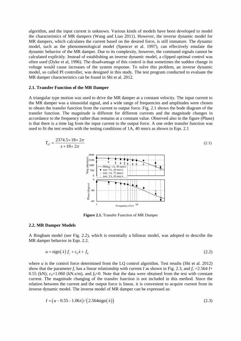
A Bingham model (see Fig. 2.2), which is essentially a bilinear model, was adopted to describe the
MR damper behavior in Eqn. 2.2.
c 0 0signu x f c x f (2.2)
where u is the control force determined from the LQ control algorithm. Test results (Shi et al. 2012)
show that the parameter fc has a linear relationship with current I as shown in Fig. 2.3, and fc =2.564 I+
0.55 (kN); c0=1.060 (kN.s/m), and f0=0. Note that the data were obtained from the test with constant
current. The magnitude changing of the transfer function is not included in this method. Since the
relation between the current and the output force is linear, it is convenient to acquire current from its
inverse dynamic model. The inverse model of MR damper can be expressed as:
0.55 1.06 / 2.564signI u x x (2.3)
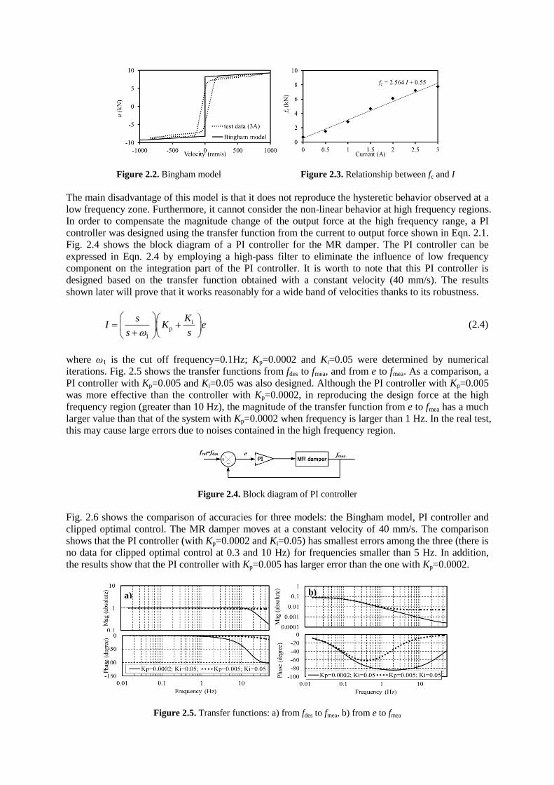
Figure 2.2. Bingham model Figure 2.3. Relationship between fc and I
The main disadvantage of this model is that it does not reproduce the hysteretic behavior observed at a
low frequency zone. Furthermore, it cannot consider the non-linear behavior at high frequency regions.
In order to compensate the magnitude change of the output force at the high frequency range, a PI
controller was designed using the transfer function from the current to output force shown in Eqn. 2.1.
Fig. 2.4 shows the block diagram of a PI controller for the MR damper. The PI controller can be
expressed in Eqn. 2.4 by employing a high-pass filter to eliminate the influence of low frequency
component on the integration part of the PI controller. It is worth to note that this PI controller is
designed based on the transfer function obtained with a constant velocity (40 mm/s). The results
shown later will prove that it works reasonably for a wide band of velocities thanks to its robustness.
ip
1
KsI K e
s s
(2.4)
where ω1 is the cut off frequency=0.1Hz; Kp=0.0002 and Ki=0.05 were determined by numerical
iterations. Fig. 2.5 shows the transfer functions from fdes to fmea, and from e to fmea. As a comparison, a
PI controller with Kp=0.005 and Ki=0.05 was also designed. Although the PI controller with Kp=0.005
was more effective than the controller with Kp=0.0002, in reproducing the design force at the high
frequency region (greater than 10 Hz), the magnitude of the transfer function from e to fmea has a much
larger value than that of the system with Kp=0.0002 when frequency is larger than 1 Hz. In the real test,
this may cause large errors due to noises contained in the high frequency region.
Figure 2.4. Block diagram of PI controller
Fig. 2.6 shows the comparison of accuracies for three models: the Bingham model, PI controller and
clipped optimal control. The MR damper moves at a constant velocity of 40 mm/s. The comparison
shows that the PI controller (with Kp=0.0002 and Ki=0.05) has smallest errors among the three (there is
no data for clipped optimal control at 0.3 and 10 Hz) for frequencies smaller than 5 Hz. In addition,
the results show that the PI controller with Kp=0.005 has larger error than the one with Kp=0.0002.
Figure 2.5. Transfer functions: a) from fdes to fmea, b) from e to fmea
b) a)
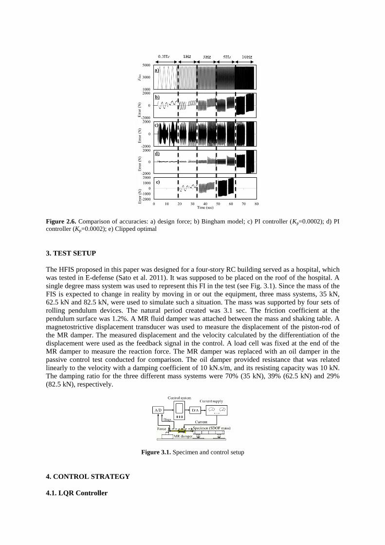
Figure 2.6. Comparison of accuracies: a) design force; b) Bingham model; c) PI controller (Kp=0.0002); d) PI
controller (Kp=0.0002); e) Clipped optimal
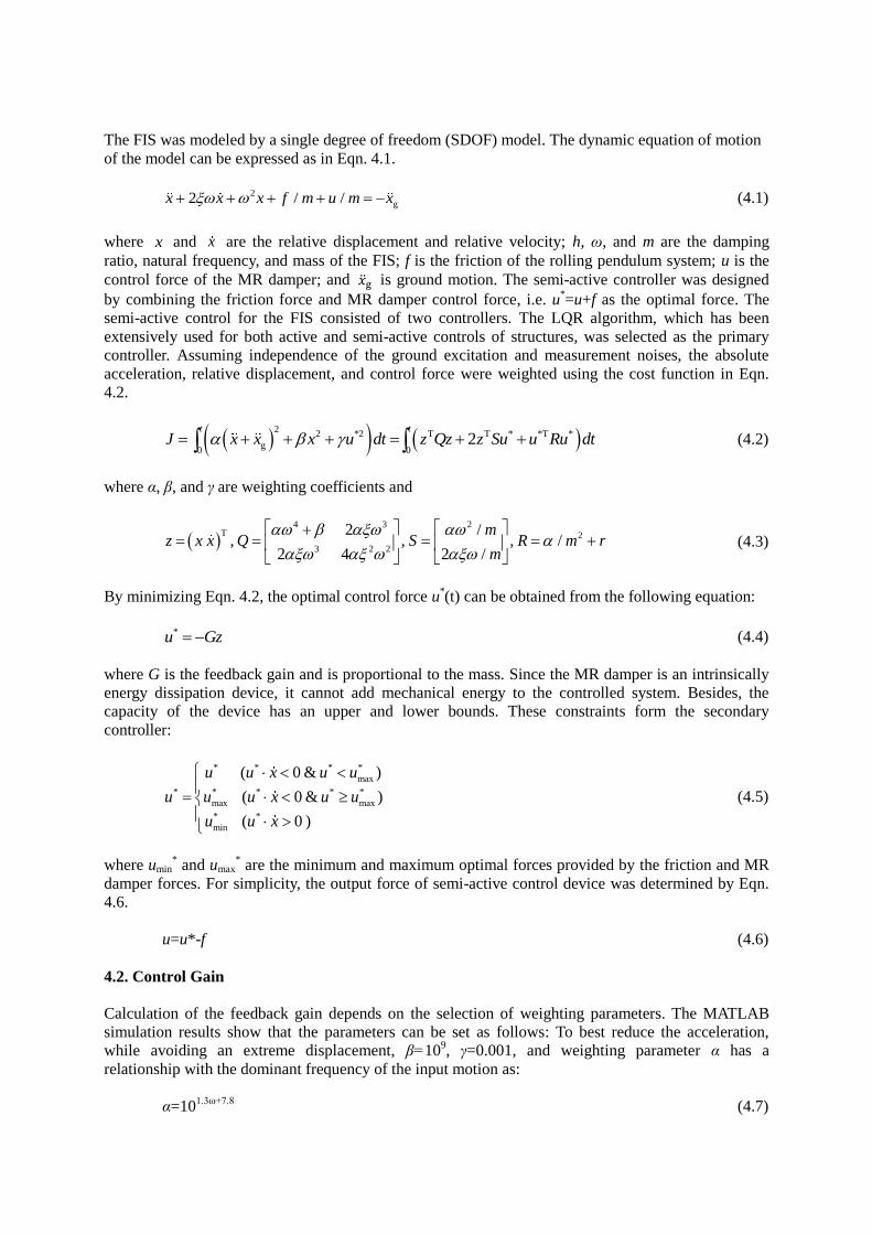
3. TEST SETUP
The HFIS proposed in this paper was designed for a four-story RC building served as a hospital, which
was tested in E-defense (Sato et al. 2011). It was supposed to be placed on the roof of the hospital. A
single degree mass system was used to represent this FI in the test (see Fig. 3.1). Since the mass of the
FIS is expected to change in reality by moving in or out the equipment, three mass systems, 35 kN,
62.5 kN and 82.5 kN, were used to simulate such a situation. The mass was supported by four sets of
rolling pendulum devices. The natural period created was 3.1 sec. The friction coefficient at the
pendulum surface was 1.2%. A MR fluid damper was attached between the mass and shaking table. A
magnetostrictive displacement transducer was used to measure the displacement of the piston-rod of
the MR damper. The measured displacement and the velocity calculated by the differentiation of the
displacement were used as the feedback signal in the control. A load cell was fixed at the end of the
MR damper to measure the reaction force. The MR damper was replaced with an oil damper in the
passive control test conducted for comparison. The oil damper provided resistance that was related
linearly to the velocity with a damping coefficient of 10 kN.s/m, and its resisting capacity was 10 kN.
The damping ratio for the three different mass systems were 70% (35 kN), 39% (62.5 kN) and 29%
(82.5 kN), respectively.
Figure 3.1. Specimen and control setup
4. CONTROL STRATEGY
4.1. LQR Controller
The FIS was modeled by a single degree of freedom (SDOF) model. The dynamic equation of motion
of the model can be expressed as in Eqn. 4.1.
2
g2 / /x x x f m u m x (4.1)
where x and x
are the relative displacement and relative velocity; h, ω, and m are the damping
ratio, natural frequency, and mass of the FIS; f is the friction of the rolling pendulum system; u is the
control force of the MR damper; and �̈�g is ground motion. The semi-active controller was designed
by combining the friction force and MR damper control force, i.e. u*=u+f as the optimal force. The
semi-active control for the FIS consisted of two controllers. The LQR algorithm, which has been
extensively used for both active and semi-active controls of structures, was selected as the primary
controller. Assuming independence of the ground excitation and measurement noises, the absolute
acceleration, relative displacement, and control force were weighted using the cost function in Eqn.
4.2.
2
2 *2 T T * *T *
g0 0
2t t
J x x x u dt z Qz z Su u Ru dt (4.2)
where α, β, and γ are weighting coefficients and
4 3 2
T 2
3 2 2
2 /, , , /
2 4 2 /
mz x x Q S R m r
m
(4.3)
By minimizing Eqn. 4.2, the optimal control force u*(t) can be obtained from the following equation:
*u Gz (4.4)
where G is the feedback gain and is proportional to the mass. Since the MR damper is an intrinsically
energy dissipation device, it cannot add mechanical energy to the controlled system. Besides, the
capacity of the device has an upper and lower bounds. These constraints form the secondary
controller:
* * * *
max
* * * * *
max max
* *
min
( 0 & )
( 0 & )
( 0 )
u u x u u
u u u x u u
u u x
(4.5)
where umin* and umax
* are the minimum and maximum optimal forces provided by the friction and MR
damper forces. For simplicity, the output force of semi-active control device was determined by Eqn.
4.6.
u=u*-f (4.6)
4.2. Control Gain
Calculation of the feedback gain depends on the selection of weighting parameters. The MATLAB
simulation results show that the parameters can be set as follows: To best reduce the acceleration,
while avoiding an extreme displacement, β=109, γ=0.001, and weighting parameter α has a
relationship with the dominant frequency of the input motion as:
α=101.3ω+7.8
(4.7)

where ω is the dominant frequency of the input motion. Two types of semi-active tests were performed.
The first one was performed by assuming that α was known, and the second one considering the actual
situation was performed by assuming that α was unknown. The control gain was updated by detecting
the frequency of the input motion in a 2.5 sec window. The frequency in the first 2.5 sec window was
used to update α, and the calculated gain was used in the next 2.5 sec window. Note that it is not a real
time control.
The input motions used in the test were the roof responses of the four-story RC building tested in
E-defense (Sato et al. 2011). The first motion JMABF was a short period type motion, which was
obtained from the response of the tested structure subjected to a near fault ground motion of 1995
JMA Kobe. The peak acceleration was 10 m/s2. Its dominant frequency was 1.4 Hz. The second
motion SANBF was a long period motion, which was the roof response of the tested structure
subjected to a synthesized ground motion named Sannomaru. The peak acceleration was 3 m/s2.
Because the dominant low frequency components of the ground motion Sannomaru were not filtered
by the structure, the roof response was still dominated at 0.35 Hz. The weighting parameter for the
acceleration was set to be 0.9α to avoid large displacements in this long period ground motion.
The short period motion often excites the structure within a short time with great power, while the
long period motion shakes the structure for a long time. It is relatively easier to update the control gain
based on the frequency information obtained from the long period motions. In such a condition, it is
recommendable that the initial value of α be set at a relatively small value to prevent possible large
acceleration responses under short period motions. For the particular case in this study, since the
dominant frequency of the motion under short period ground motion was close to the frequency of the
first mode of the superstructure, i.e. 1.4 Hz, α can be set to 9.6 (see Eqn. 4.7) at the initial stage.
5. HYBRID FLOOR ISOLATION TEST
Fig. 5.1 shows the test results for the three different mass systems with passive control and two types
of semi-active control.
Figure 5.1. Shaking table test results for three control strategies
Fig. 5.1 indicates that the semi-active control could maintain similar control results for different mass
systems thanks to its ability to adjust the gain which was proportional to the mass. The response of the
FI with passive control could not always stay at an optimal state for different mass systems (different
damping). Under JMABF input motion, the acceleration in the semi active control case was reduced

by 33%-73% when compared with the passive control case while both of the two controls remained
very close displacement responses; Under SANBF input motion, the acceleration of both the passive
and semi-active control for the 62.5 kN system remained similar, but the displacement in the
semi-active case was reduced by 23% when compared with the passive control case. Pounding
occurred for the passive control and was avoided for semi-active control in the 82.5 kN system .
Although in the 35 kN system the passive control reduced the displacement by 18% compared with the
semi-active control and had similar acceleration response with semi-active control, but at the expense
of a super high damping ratio of 70%.
The semi-active control was able to automatically detect the frequency of the input motion and
consequently adjusted the control gain (see the data for 62.5 kN system). The test results for the
semi-active control with the updated gains gave similar results compared with the semi-active control
with a pre-determined gain, which is not realistic in the actual application.
Fig. 5.2 shows the current calculated by the PI controller, comparison between the design force by
LQR algorithm and the actual measured force. The relative velocity is also included in the figure. The
resutls show that the PI controller could track the design force with great accuracy, especilly for
SANBF gound motion. The error at the maximum control force point and the RMS error were 1000 N
(with maximum control force of 6100 N) and 278 N, respectively, under JMABF input motion; and
they were 402 N (with maximum control force of 6901 N) and 277 N, respecitively, under SANBF
input motion. The maximum velocities under those two motions were 1.04 m/s and 0.4 m/s,
respectively. The results show that the PI controller designed based on the results with velocity of 0.04
m/s was very robust.
Figure. 5.2. Applied current and the comparison of design and real measured forces
6. CONCLUSIONS
A floor isolation system with semi-active control was developed to protect important equipment and
facilities. A series of shaking table tests was performed to validate the properties of the adopted MR
damper, and the control strategies were developed. The inverse dynamic model developed was proven
to be effective which could track the design force accurately. The floor isolation was tested under
passive and semi-active control conditions. The test results show that the acceleration was 33%-73%
smaller in the semi-active control case than in the passive control case under the short period JMABF
ground motion, while both the two controls maintained similar displacement response; the
displacement was 23% smaller in the semi-active control case than in the passive control case while
maintaining similar acceleration response under SANBF long period ground motions for a 62.5 kN
system. And pounding was avoided in the semi-active control. An algorithm for auto gains was

designed, in which the frequencies characteristics of the input motion were detected and based on the
dominate frequency the control gain was updated automatically. The test results for the semi-active
control with the auto gains gave similar results compared with the semi-active control with a
pre-determined gain.
REFERENCES
Dyke, S.J, Spencer, B.F, Sain, M.K and Carlson, J.D. (1996). Modelling and control of magnetorheological
dampers for seismic response reduction, Smart Materials and structures, 5,565-575.
Nagrajaiah, S. and Sun, X.(2000). Response of base-isolated USC hospital building in Northridge earthquake,
Journal of structural engineering, 126, 1177-1186.
Sato, E., Furukawa, S., Kakehi, A. and Nakashima, M.(2011). Full-scale shaking table test for examination of
safety and functionality of base-isolated medical facilities, Journal of Earthquake Engineering and
Structural Dynamics, 40, 1435-1453.
Shi, Y., Sato, E., Hoki, K. and Nakashima, M.(2012). Test on hybrid floor isolation system with semi-active
control, 9th International Conference on Urban Earthquake Engineering/ 4th Asia Conference on
Earthquake Engineering, 1459-1464.
Spencer, B.F., Dyke, S.J, Sain, M.K and Carlson, J.D. (1997). Phenomenological Model of a
Magnetorheological Damper, Journal of engineering mechanics, 123:3, 230-238.
Wang, D.H and Liao, W.H. (2011). Magnetorheological fluid dampers: a review of parametric modelling, Smart
Materials and structures, 20:2, 1-34
Yoshioka, H., Ramallo, J. and Spencer, B.(2002). “Smart” base isolation strategies employing
magnetorheological dampers, Journal of engineering mechanics, 128, 540-551.