Development of Electro-hydraulic Actuator with Fail-safe ...
7
131 QR of RTRI, Vol. 55, No. 3, Aug. 2014 Yasuhiro UMEHARA Running Gear Laboratory Development of Electro-hydraulic Actuator with Fail-safe Function for Steering System Shogo KAMOSHITA Vehicle Noise and Vibration Laboratory, Vehicle Structure Technology Division Kotaro ISHIGURI Yusuke YAMANAGA 1. Introduction A type of bogie angle linked steering truck which steers the wheelsets depending on the relative yaw angle between the car body and the truck is able to significantly reduce wheel lateral forces when passing through a curve [1]. However, the problem with this system is that the reducing effect on wheel lateral forces is smaller in transition curve sections than in circular curve sections because the steer- ing device specifications are determined by its geometric shape in a circular curve. In order further to reduce wheel lateral forces in transition curve sections, a power-assisted steering system was developed to make the controlled steering force work in the turning direction of the truck [2]. It is expected that a bogie angle linked steering truck using this system will show excellent curving performance over the whole length of a curve section including transition curves. However, since lateral forces increase when the steering force works in the wrong direction in this system, it is essential to ensure the fail-safe function works prop- erly to prevent accidents in practice. Moreover, if hydraulic actuators are used in the steering system to obtain the con- trol force necessary for steering wheelsets, problems such as hydraulic oil contamination by dust may arise because desorbing of hydraulic pipes is need during truck mainte- nance. This paper reports on the development of the steer- ing electro-hydraulic actuator (hereinafter referred to as “steering EHA”) for improving the maintainability and the fail-safe hydraulic circuit for preventing the wrong steering operations which are the biggest problem with ac- tive steering systems [3]. 2. Power-assisted steering system 2.1 Bogie angle linked steering truck and steering actuator The fundamental structure of a bogie angle linked steering truck with a steering EHA is shown in Fig. 1. Steering levers and steering links are placed in this truck to steer wheelsets depending on the relative yawing angle (bogie angle) between the steering beam and the truck frame. In the curve section, the steering device expands the outer wheelbase and shortens the inner wheelbase me- chanically depending on the bogie angle, then the lateral force is decreased by reducing the angle of attack. The power-assisted steering system includes a steering actuator between the truck frame and the steering beam. In order to improve the curving performance in the transi- Running Gear Laboratory, Vehicle Structure Technology Division Bogie angle linked steering trucks have an excellent curving performance in circular curve sections. In order to gain even greater curving performance, a power-assisted steering system was developed for reducing wheel lateral forces in transition curve sections by generat- ing the control force in the turning direction of the steering truck. In addition, a steering elec- tro-hydraulic actuator was designed for reducing lateral forces in transition curve sections while preventing wrong direction steering operation which is the biggest problem with active steering systems. Finally, confirmation was obtained through running test on a test line that this steering actuator improved steering performance and maintained the fail-safe function. Keywords: fail-safe, hydraulic circuit, electro-hydraulic actuator, steering truck, lateral force Fig. 1 Bogie angle steering truck and steering actuator Steering beam Truck frame Wheelset Steering lever Steering link Side bearer Steering actuator PAPER
Transcript of Development of Electro-hydraulic Actuator with Fail-safe ...

131QR of RTRI, Vol. 55, No. 3, Aug. 2014
Yasuhiro UMEHARARunning Gear Laboratory
Development of Electro-hydraulic Actuator with Fail-safe Function for Steering System
Shogo KAMOSHITAVehicle Noise and Vibration Laboratory,
Vehicle Structure Technology Division
Kotaro ISHIGURI Yusuke YAMANAGA
1. Introduction
A type of bogie angle linked steering truck which steers the wheelsets depending on the relative yaw angle between the car body and the truck is able to significantly reduce wheel lateral forces when passing through a curve [1]. However, the problem with this system is that the reducing effect on wheel lateral forces is smaller in transition curve sections than in circular curve sections because the steer-ing device specifications are determined by its geometric shape in a circular curve. In order further to reduce wheel lateral forces in transition curve sections, a power-assisted steering system was developed to make the controlled steering force work in the turning direction of the truck [2]. It is expected that a bogie angle linked steering truck using this system will show excellent curving performance over the whole length of a curve section including transition curves. However, since lateral forces increase when the steering force works in the wrong direction in this system, it is essential to ensure the fail-safe function works prop-erly to prevent accidents in practice. Moreover, if hydraulic actuators are used in the steering system to obtain the con-trol force necessary for steering wheelsets, problems such as hydraulic oil contamination by dust may arise because desorbing of hydraulic pipes is need during truck mainte-nance.
This paper reports on the development of the steer-ing electro-hydraulic actuator (hereinafter referred to as “steering EHA”) for improving the maintainability and the fail-safe hydraulic circuit for preventing the wrong steering operations which are the biggest problem with ac-tive steering systems [3].
2. Power-assisted steering system
2.1 Bogie angle linked steering truck and steering actuator
The fundamental structure of a bogie angle linked steering truck with a steering EHA is shown in Fig. 1. Steering levers and steering links are placed in this truck to steer wheelsets depending on the relative yawing angle (bogie angle) between the steering beam and the truck frame. In the curve section, the steering device expands the outer wheelbase and shortens the inner wheelbase me-chanically depending on the bogie angle, then the lateral force is decreased by reducing the angle of attack.
The power-assisted steering system includes a steering actuator between the truck frame and the steering beam. In order to improve the curving performance in the transi-
Running Gear Laboratory, Vehicle Structure Technology Division
Bogie angle linked steering trucks have an excellent curving performance in circular curve sections. In order to gain even greater curving performance, a power-assisted steering system was developed for reducing wheel lateral forces in transition curve sections by generat-ing the control force in the turning direction of the steering truck. In addition, a steering elec-tro-hydraulic actuator was designed for reducing lateral forces in transition curve sections while preventing wrong direction steering operation which is the biggest problem with active steering systems. Finally, confirmation was obtained through running test on a test line that this steering actuator improved steering performance and maintained the fail-safe function.
Keywords: fail-safe, hydraulic circuit, electro-hydraulic actuator, steering truck, lateral force
Fig. 1 Bogie angle steering truck and steering actuator
Steering beam Truck frame
Wheelset
Steering leverSteering link
Side bearer
Steering actuator
PAPER
132 QR of RTRI, Vol. 55, No. 3, Aug. 2014
tion curve section, the actuator generates steering forces to reduce the friction force by a set of side bearers. As for the steering control method, since the control target is the transition curve section, we adopted a preview control method in order to improve the control effect.
2.2 Development of an electro-hydraulic actuator for the steering truck
A new electro-hydraulic actuator was developed for the power-assisted steering system. The major feature of this device is that the hydraulic cylinder, a pump and a mo-tor are integrated. Therefore, since there are no hydraulic piping couplings outside the actuator, maintainability is improved. Moreover, this device has a large generating force and excellent response by using a hydraulic system while still being small enough to be mounted in the avail-able space on the truck. Figure 2 shows the appearance of the steering EHA installed on a truck and Table 1 gives its main specifications.
Table 1 Specifications of the steering actuator
Rated force ± 34 kN
Maximum force ± 55 kN
Maximum speed 14 mm/sec
Stroke 81 mm
Maximum steering torque ± 21 kN・m
Fig. 2 Electro-hydraulic actuator for steering trucks
MotorPump
Truck
Steering
Hydraulic actuator
beam
frame
3. Running test on test line
Running tests were carried out on a test line using the bogie-angle linked steering truck equipped with the steer-ing EHA. In the running test, a diesel locomotive drove a test car mounted on the steering truck equipped with a measuring wheelset of wheel, rail contact force on the front side. The rear truck on the car was a normal bolsterless truck. The running test conditions were set to make the test car run through a test curve section (radius: 100 m, cant: 90 mm) at about 20 km/h. The command of the steering control was to ramp up the steering force at the beginning of the transition curve section, to maintain the constant steering force during the transition curve section, and to remove the steering force after entering into the circular
curve section or straight section. We grasped the relation-ship between the lateral force and the steering force by us-ing simulation in advance, and obtained measured data by increasing the steering force gradually maintaining safety throughout. The vehicle running position required for the steering control was calculated by the wheel diameter and pulses generated by the tachometer generator based on the detected position of the reflection sheet disposed on the track.
Figure 3 shows the inner and outer wheel lateral force of the leading wheelset, the steering force (steering EHA’s generative force which was calculated from the cylinder pressure) and the bogie angle. “Non control” means a test where a bogie angle linked steering truck was equipped with a steering EHA which did not work. “Steering con-trol” means a test where the steering EHA generated the steering force according to the turning direction of the truck in the transition curve sections (distance: 20-75 m, 135-175 m). And “Reverse steering control” means a test where the steering EHA generated the steering force in the direction of opposite to the turning direction of the truck in the transition curve sections. It was verified that the outer lateral force was reduced by the steering force at the entry of the transition curve. However, during reverse steering control tests, it was observed that the outer lateral force increased in the entry transition curve. Incidentally, it should be noted that these showed some steep changes due to irregularities such as rail joints.
Figure 4 shows the relationship between the steering force and the mean outer wheel lateral force in the entry transition curve. A linear relationship was observed between the steering force and the mean outer wheel lateral force. In addition, we confirmed that “Steering control (55 kN)” ap-plying the maximum steering force could reduce the mean outer wheel lateral force in the entry transition curve sec-tion by approximately 60 % compared to “Non control (0 kN)” condition.
Fig. 3 Results of the running test
0
2
4
Bog
ie a
ngle
[deg
]
-20
0
20
40
Out
er la
tera
l for
ce[k
N]
-40
-20
0
20
Inne
r lat
eral
forc
e[k
N]
0 50 100 150 200-50
050
Distance [m]
Stee
ring
forc
e[k
N]
Reverse steering controlNon controlSteering control

133QR of RTRI, Vol. 55, No. 3, Aug. 2014
Fig. 4 Mean outer wheel lateral force at the entry of the transition curve
-55.000010+20
Reverse steering
Non control
Steering control
-55 -34 -20 0 +20 +34 +55Steering force [kN]
0
5
10
15
20
Mea
n ou
ter l
ater
al fo
rce
[kN
]
Control (-)
(+)
4. Improvement of the fail-safe function
4.1 Fail-safe hydraulic circuit
This power-assisted steering system generates the control steering force in the turning direction of the truck by the steering EHA in order to reduce the wheel lateral force in the transition curve section. However, if the steer-ing EHA applies a force in the opposite direction, the wheel lateral force will rise as shown in Fig. 4. Therefore, it is essential to ensure a fail-safe function, which prevents re-verse steering in practice. Although fail-safe methods using electronic sensors exist, this paper explains the mechanical approach to avoiding failure.
In the case of the reverse steering operation, the pres-sure of the steering EHA’s cylinder is high because the pump supplies oil in the direction which inhibits the turn-ing motion of the truck. It is possible to suppress the con-trol pressure by using the relief valve thereby reducing the influence of reverse steering when the pressure of the cyl-inder exceeds a specified level. However, the steering force is limited by the relief pressure. For the reasons stated above, the fail-safe device is required a mechanism which
Fig. 5 Fail-safe hydraulic circuit
Fig. 6 Inner structure of the spool valve
M
Cylinder
Pump
Motor
Spool valve
c3 c4
c2c1
ALD1L
BL
D2LP1L
CL
AR D1R
BR
D2R
P1R
CR
System RSystem L
Check valve
SleeveSpring
Spool
A D1
B
D2 P1
C
Port
controls the steering force by releasing oil in the cylinder at the lower specified pressure only in case of the reverse steering. A hydraulic circuit was thus developed to avoid failure scenarios based on combining relief circuits and valves whose function is to discern the agreement between the control direction and the actual stretching direction of the cylinder. Hereinafter, this circuit is referred to as the “fail-safe hydraulic circuit”.
Figures 5 and 6 show the schematic drawing of the fail-safe hydraulic circuit and the inner structure of the spool valve. A fail-safe hydraulic circuit composed of four check valves and two spool valves was attached between the elec-tric hydraulic pump and the hydraulic cylinder. The spool valve has a spool which is held on one side by the spring in the sleeve having six ports. Its mechanism is based on the principle that the flow path opens or closes as the spool is moved in the axial direction by the balance of the elastic force of the spring and the pressure of port B and port C.
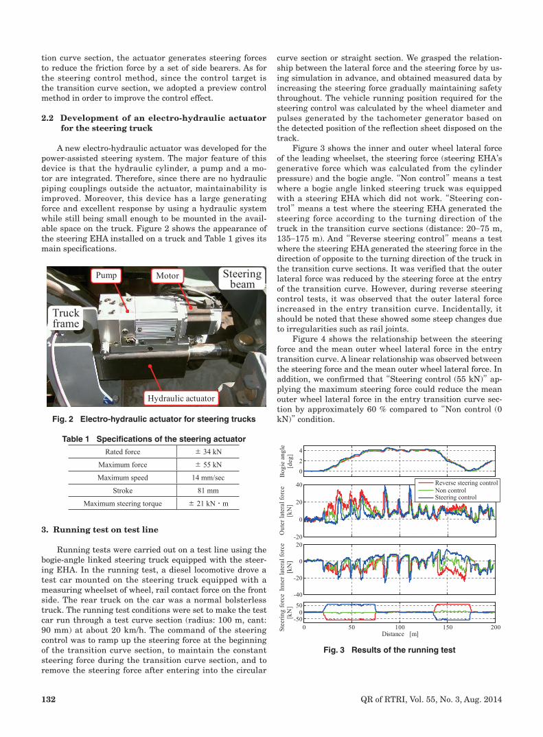
Figure 7 shows the oil flow in the steering operation. In this figure, system ‘L’ is the rod side of the hydraulic circuit, and system ‘R’ is other side. If the actuator piston is displaced towards ‘L’ by external forces from the steer-ing beam at the same time that the pump pressurizes R side of the cylinder to displace the piston towards L, i.e., if the steering control direction is correct, the oil supplied to the hydraulic circuit from the pump enters R side of the cylinder through the spool valve (P1R → AR) and the check valve (c2). Consequently, the fail-safe hydraulic circuit does not disturb the movement of the steering actuator, and the steering force is generated.
In contrast, Fig. 8 shows the oil flow in the case of re-verse steering. If the cylinder piston is displaced towards R by external forces from the steering beam while the pump simultaneously pressurizes R side of the cylinder to dis-place the piston towards L, in other words, if the steering control direction is wrong, the relief circuit (CR → D1R) for releasing oil in R side of the cylinder is appeared by the function of the spool valve when the pressure in R side of the cylinder increases because of the action in the reverse direction. At the same time, since the spool valve makes a bypass circuit (P1R → D2R), the hydraulic oil supplied from the pump flows to the low pressure side of the pump via the spool valve in R and the pump cannot supply hydraulic oil to the cylinder. Therefore, no steering force is generated even though the pump is operating, and the steering EHA does not disturb the movement of the truck. Since the fail-safe circuit in L is constructed symmetrically to that in R, these circuits will behave similarly even when the direction of the operation described above is reversed.
134 QR of RTRI, Vol. 55, No. 3, Aug. 2014
4.2 Operational verification test and hydraulic cir-cuit simulation
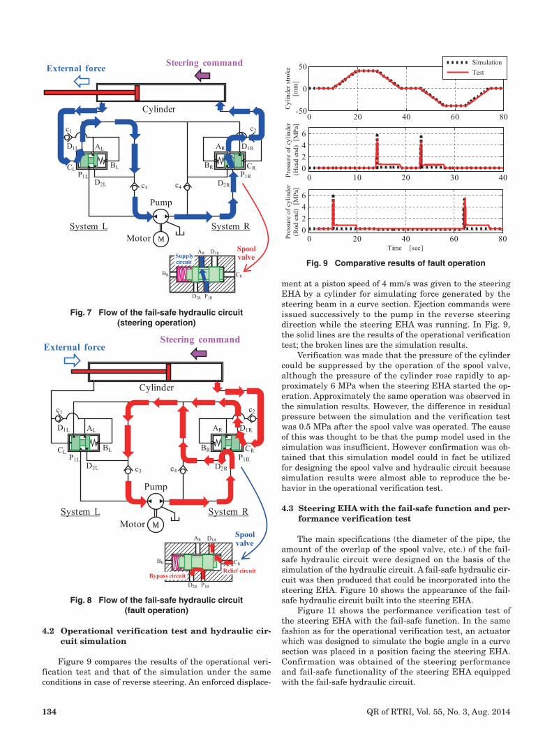
Figure 9 compares the results of the operational veri-fication test and that of the simulation under the same conditions in case of reverse steering. An enforced displace-
Fig. 7 Flow of the fail-safe hydraulic circuit(steering operation)
Fig. 8 Flow of the fail-safe hydraulic circuit(fault operation)
M
Steering commandExternal force
Cylinder
Pump
Motor
c3 c4D2L D2R
System RSystem L
AR D1R
BR
D2R P1R
CR
SupplySpoolvalve
circuit
c2c1
ALD1L
BLP1L
CL
AR D1R
BRP1R
CR
M
c3 c4
c2c1
ALD1L
BL
D2L
P1LCL
AR D1R
BR
D2R
P1R
CR
AR D1R
BR
D2R P1R
CR
Relief circuitBypass circuit
External forceSteering command
Cylinder
Pump
MotorSystem RSystem L
Spoolvalve
Fig. 9 Comparative results of fault operation
0 20 40 60 80-50
0
50
Cylin
der s
troke
[mm
]
SimulationTest
0 10 20 30 400246
Pres
sure
of c
ylin
der
(Hea
d en
d) [
MPa
]
0 20 40 60 800246
Time [sec]
Pres
sure
of c
ylin
der
(Rod
end
) [M
Pa]
ment at a piston speed of 4 mm/s was given to the steering EHA by a cylinder for simulating force generated by the steering beam in a curve section. Ejection commands were issued successively to the pump in the reverse steering direction while the steering EHA was running. In Fig. 9, the solid lines are the results of the operational verification test; the broken lines are the simulation results.
Verification was made that the pressure of the cylinder could be suppressed by the operation of the spool valve, although the pressure of the cylinder rose rapidly to ap-proximately 6 MPa when the steering EHA started the op-eration. Approximately the same operation was observed in the simulation results. However, the difference in residual pressure between the simulation and the verification test was 0.5 MPa after the spool valve was operated. The cause of this was thought to be that the pump model used in the simulation was insufficient. However confirmation was ob-tained that this simulation model could in fact be utilized for designing the spool valve and hydraulic circuit because simulation results were almost able to reproduce the be-havior in the operational verification test.
4.3 Steering EHA with the fail-safe function and per-formance verification test
The main specifications (the diameter of the pipe, the amount of the overlap of the spool valve, etc.) of the fail-safe hydraulic circuit were designed on the basis of the simulation of the hydraulic circuit. A fail-safe hydraulic cir-cuit was then produced that could be incorporated into the steering EHA. Figure 10 shows the appearance of the fail-safe hydraulic circuit built into the steering EHA.
Figure 11 shows the performance verification test of the steering EHA with the fail-safe function. In the same fashion as for the operational verification test, an actuator which was designed to simulate the bogie angle in a curve section was placed in a position facing the steering EHA. Confirmation was obtained of the steering performance and fail-safe functionality of the steering EHA equipped with the fail-safe hydraulic circuit.

135QR of RTRI, Vol. 55, No. 3, Aug. 2014
Fig. 10 Steering EHA with the fail-safe hydraulic circuit
Fig. 11 Performance verification test of the steering EHA
Fail-safehydrauliccircuit
Motor
Pump
Hydrauliccylinder
External force cylinderSteering EHAwith fail-safefunction
(simulated external force by steering beam)
Figures 12 and 13 show the results of the performance verification tests. In case of steering, it was confirmed that a normal steering force was generated and that the fail-safe hydraulic circuit did not inhibit behavior. Further, in case of reverse steering, verification was made that the steering EHA had the fail-safe function since the steering force did not generated by a decrease in the cylinder pres-sure even though a steering command was given.
Fig. 12 Result of the performance verification test(steering)
0 5 10 15 200
5
10
15
0 5 10 15 20-60
-30
30
60
0 5 10 15 20-60
-30
30
60
Forc
e co
mm
and
[kN
]
Stee
ring
forc
e [k
N] Expanding
directionShorteningdirection
Cyl
inde
r st
roke
[m
m]
Time [sec]
0
0
5. Performance verification running test of the fail-safe function
Performance tests were carried out on a test line us-ing the bogie angle linked steering truck equipped with the steering EHA which had the fail-safe function under test conditions similar to those in Chapter 3 (Fig. 14). Figure 15 shows the outer lateral force of the leading wheelset, the pressure of the cylinder and the steering command against the distance on the horizontal axis. This confirmed that the outer lateral force was reduced by the steering control system in the entry transition curve. During reverse steer-ing control, the fail-safe hydraulic circuit ensured that no steering force was generated by the decreasing cylinder pressure even though the steering command was given in the transition curve. Moreover, the outer lateral force in case of reverse steering control showed the same trend as with ‘non control’.
Figure 16 shows the steering force and the mean outer wheel lateral force at the entry of the transition curve. Compared with Fig. 4, there was almost no increase in the mean outer wheel lateral force due to the fail-safe circuit even though the command value was increased under the reverse steering control. This demonstrated that the fail-safe function in the power-assisted steering system was effective even in a real vehicle. In addition, under steering control, results showed that the mean outer wheel lateral force fell as the steering force rose. In Fig. 15, the cylin-der pressure of the steering control was rapidly decreased around 40-50 m. It was considered that the fail-safe hy-draulic circuit was operated because the pressure of the cylinder was varied by external forces produced when the truck ran through irregularities such as rail joints. How-ever, it was expected that the effective values of the steer-ing force would not be influenced by this phenomenon since these effects were instantaneous.
The steering EHA with the fail-safe function deter-mines the steering force to be generated by detecting the change in external forces exerted in a transition curve sec-tion. There was thus a concern that running stability could
Fig. 13 Result of the performance verification test(reverse steering)
0 5 10 15 200
5
10
15
0 5 10 15 20-60
-30
0
30
60
0 5 10 15 20-60
-30
0
30
60Expanding direction
Shorteningdirection
Cyl
inde
r st
roke
[m
m]
Forc
e co
mm
and
[kN
]
Stee
ring
forc
e [k
N]
Time [sec]

136 QR of RTRI, Vol. 55, No. 3, Aug. 2014
be influenced by hunting in the spool valve or the steering force if the steering command was input in a straight sec-tion. Considering the above, running tests were conducted which input a steering force when the truck was coast-ing at 10 km/h on a straight section. Figure 17 shows the lateral force in the leading wheelset, the pressure of the
Fig. 14 Performance verification running test
Fig. 16 Mean outer wheel lateral force at the entry of the transition curve (with fail-safe function)
Fig. 15 Result of the running test(with the fail-safe function)
-40.000001
0
40
0
5
10
15
20
-40 -20 0 +20 +40
Reverse steering
Non control
Steering control
Steering force [kN]
Mea
n ou
ter l
ater
al fo
rce
[kN
]
control
cylinder and the steering command against the distance on the horizontal axis. Under straight steering control, the pressure of the cylinder was instantaneously increased by the steering command. However, it was confirmed that the pressure of the cylinder decreased due to operation of the fail-safe hydraulic circuit because the steering beam did not turn by virtue of the friction force from the side bearer. Moreover, compared with the results under ‘non control’ conditions, it was possible to verify that the steering EHA had the fail-safe function even when the truck was running on a straight section because the wheel lateral force barely changed. 6. Conclusions
A steering EHA was developed for the bogie angle linked steering truck. Its performance in reducing wheel lateral forces in transition curve sections was confirmed through running tests. Moreover, in order to avoid failures such as reverse steering, a hydraulic circuit with a mechani-cal fail-safe function was devised, and its fundamental per-formance was confirmed through performance verification tests and numerical simulation. Finally, this hydraulic cir-cuit produced on the basis of hydraulic simulation results was incorporated into the steering EHA, and confirmation was found that this hydraulic circuit maintained the fail-safe function and improved steering performance in tran-sition curves through bench tests and running tests on a test line. Running stability in straight sections was not hindered by this system.
References
[1] Sato, E., Kobayashi, H., Tezuka, K., Okamoto, I., Kak-inuma, H. and Tamaoki, T., “Lateral force during curve negotiation of forced steering bogies,” QR of RTRI, Vol. 44, No. 1, pp. 8-14, 2003.
Fig. 17 Results of the running tests(steering control in a straight section)
-10
0
10
20
30
40
Out
er la
tera
l for
ce
[k
N]
-20
0
20
Pres
sure
of c
ylin
der
[MPa
]
0 20 40 60 80 100 120 140 160 180 200-60-30
03060
Distance [m]
Forc
e co
mm
and
[kN
]
Reverse steering controlNon controlSteering control
-20
0
20
40
Lat
eral
forc
e (L
eft s
ide)
[kN
]
-20
0
20
Pres
sure
of
cylin
der [
MPa
]
0 5 10 15 20 25 30 35 40-60-30
030
Distance [m]Stee
ring
com
man
d[k
N]
-40
-20
0
20
Late
ral f
orce
(Rig
ht s
ide)
[kN
]
Non controlSteering control

137QR of RTRI, Vol. 55, No. 3, Aug. 2014
[2] Kamoshita, S., Ishige, M., Umehara, Y., Yamanaga, Y. and Ishiguri, K., “An application of assist steering system for bogie angle linked steering truck,” RTRI Report, Vol. 26, No. 3, pp. 17-22, 2012 (in Japanese).
[3] Ishiguri, K., Shimoda, K., Yamanaga, Y., Kamoshita, S. and Ishige, M., “Analysis of Failsafe Hydraulic Actua-tion System using Passive Relief Valves; Application for Power Assisting Devices,” Proceedings of 8th JFPS International Symposium on Fluid Power, pp. 413-418, 2011.
Authors
Yasuhiro UMEHARAAssistant Senior Researcher, Running GearLaboratory, Vehicle Structure TechnologyDivisionResearch Areas: Steering Control System,Running Gear Structure, Vehicle Dynamics
Shogo KAMOSHITA, Ph. D.Senior Researcher, Vehicle Noise andVibration Laboratory, Vehicle StructureTechnology DivisionResearch Areas: Control TechnologyApplication, Vehicle Dynamics
Kotaro ISHIGURI, Ph. D.Assistant Senior Researcher, Running GearLaboratory, Vehicle Structure TechnologyDivisionResearch Areas: Running Gear Structure,Vehicle Dynamics, Fluid Power Engineering
Yusuke YAMANAGAAssistant Senior Researcher, Running GearLaboratory, Vehicle Structure TechnologyDivisionResearch Areas: Running Gear Structure,Vehicle Dynamics Simulation