DEVELOPMENT OF ELECTRICAL PENUATIC CONTROL TRAINER...
32
DEVELOPMENT OF ELECTRICAL PENUATIC CONTROL TRAINER KIT STUDENT NAME:- GUIDE NAME:- PATEL KEVINS D. Prof. H.C.PATEL PATEL BHAVIK G. GROUP NO :- 34 PATEL JAIMIN K. TEAM NO:- 40288 PATEL NIRAV N. Smt.S.R.Patel Engineering college ,Dabhi,Unjha-384170 (At Gujarat Technical University) 1
Transcript of DEVELOPMENT OF ELECTRICAL PENUATIC CONTROL TRAINER...

DEVELOPMENT OF ELECTRICAL
PENUATIC CONTROL TRAINER
KIT
STUDENT NAME:- GUIDE NAME:-PATEL KEVINS D. Prof. H.C.PATEL
PATEL BHAVIK G. GROUP NO :- 34
PATEL JAIMIN K. TEAM NO:- 40288
PATEL NIRAV N.
Smt.S.R.Patel Engineering college ,Dabhi,Unjha-384170
(At Gujarat Technical University) 1

`
2

OUTLINE
• Introduction
• Objective
• Scope Of Work
• Methodology
• Literature review
• Conclusion
3

INTRODUCTION
• A pneumatic system is a system that uses compressedair to transmit and control energy. Pneumatic systemsare power systems using compressed air as a workingmedium for the power transmission. Their principle ofoperation is similar to that of the hydraulic powersystems. An air compressor converts the mechanicalenergy of the prime mover into, mainly, pressure energyof the compressed air. This transformation facilitates thetransmission, storage, and control of energy. Manyfactories have equipped their production lines withcompressed air supplies and movable compressors.
• Handling of work pieces (such as clamping, positioning,separating, stacking, rotating) , packaging, filling,opening and closing of doors.
4

OBJECTIVE
• Development of electric pneumatic control trainer kit.
• Development of electric pneumatic control trainer kit.
• To reduction in cost of kit.
• Development of automation of paper making bowl
machine.
• To reduce labor cost.
5

SCOPE OF WORK
• Our main purpose is to use this kit in college practical lab
for student practical knowledge.
• Use in automation industries(We apply this system in
automation of bowl making machine).
6

METHODOLOGY
• START
• LETRATURE REVIEW
• INFORMATION ABOUT COMPONENT
• FABRICATION
• TESTING
• APPLICATION
• REPORT
7

LETRATURE REVIEW
• (1)Electiro-Pneumatic Actuator
• Inventor:-Assignee: Magnavox Government and Industrial
• Electronics Company, Fort Wayne Ind.
• Registration Date:-4 JULY 1990
• Patent Number:-4,942,852
• A bitable electronically controlled pneumatically powered transducer for use, for example, as a valve mechanism actuator in
an internal combustion engine is disclosed. The transducer has a piston which is coupled toan engine valve, for example.
The piston is powered bya pneumatic source and is held in each of its extreme positions, and air control valves are held in
their closed positions by pressurized air and/or permanent magnet latching arrangements and the control valves are
released there from to supply air to the piston, and the piston is released there from to be pneumatically driven to the other
extreme position by an electromagnetic neutralization of the permanent magnet field. The piston forms a part of the magnetic
latching circuit and that magnetic circuit also includes a radically slotted ferromagnetic member to both complete the
magnetic circuit and provide a good air communication path from a high pressure air inlet to the control valve. A pair of
auxiliary pistons movable with the piston compress air to a pressure above the pressure of the pneumatic source for aiding
recourse of the control valves as well as aiding maintenance of those control valves in their closed positions thereby
reducing the size and cost of the latching permanent magnets.
• (2) ELECTROPNEUMATIC POSITIONER
• Inventor:-FumloNagasaka, Tokyo, Japan
• Registration Date:-3 AUG. 1999
• Patent Number:-5,931,180
• An electro pneumatic positioned includes a data processing control section and an electropneumat1c converter. The control
section includes first and second position determining sections and a signal setting section. The first position determining
section obtains the valve opening degree positions of a regulating valve as the minimum and maximum pressure is set to the
minimum Signal and the maximum signal. The second position determining section obtains the Valve Opening degree
position of the Valve is Set When the driving signal is the minimum signal on the basis of the relative positional relationship
between the obtained minimum and maximum valve opening degree positions and the valve plug form of the valve. The
signal setting section sets relationship between the maximum and minimum signals A of electrical Signals and fun Opening
and Closing directions corresponding to valve opening degrees of the valve.
•
8

• 3)DOUBLE-ACTING ELECTROPNEUMATIC POSITIONER
• Inventor:-Mathias Regel,Gruendau Germany
• Registration Date:-10 AUG 1999
• Patent Number:-5,934,169
• A double-acting electro pneumatic positioner for controlling an actuator, the actuatorhaving a first and second chamber, comprises a single-acting electro pneumaticpositioner which provides an output pneumatic pressure to the first chamber of theactuator. A pressure inverter, coupled to the single acting electro pneumaticpositioner, inverts the output pneumatic pressure. The inverted output pneumaticpressure is then coupled to the second chamber of the actuator.
•
• (4)ELECTROPNEUMATIC POSITIONER
• Inventor:-Michael Loechner, Filderstadt,Germany
• Registration Date:-5 SEPT 2000
• Patent Number:-6,112,638
• The present invention includes an electro pneumatic positioner having an externalbinary input block which provides access to the electrical output of an integralelectronic position controller to control operation of a valve relay. The inventionenables manual control of the positioner for safety, maintenance etc.
9
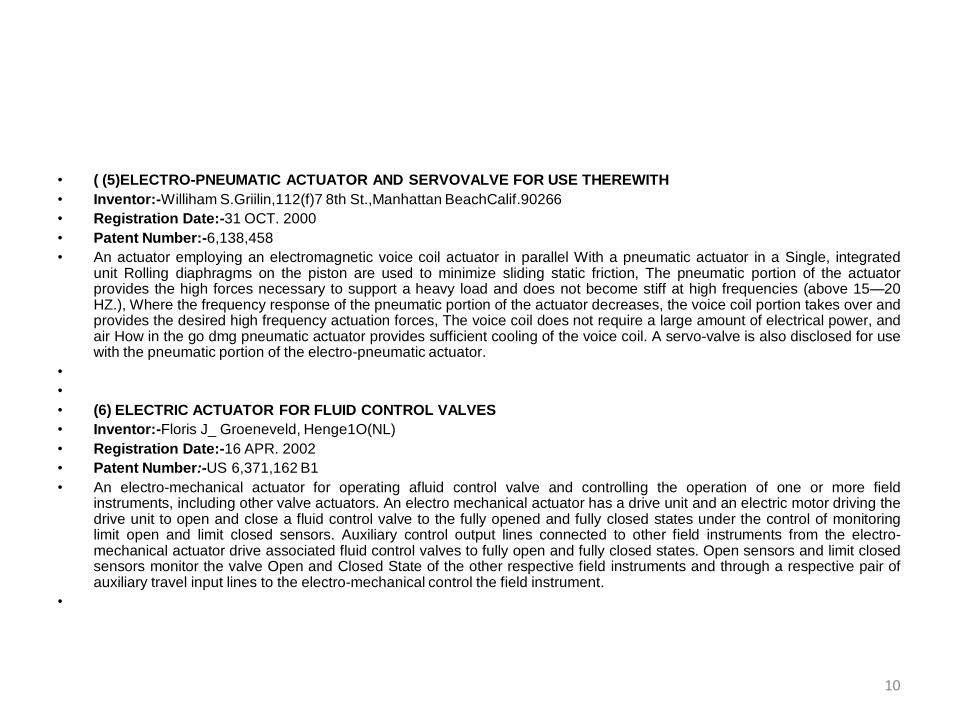
• ( (5)ELECTRO-PNEUMATIC ACTUATOR AND SERVOVALVE FOR USE THEREWITH
• Inventor:-Williham S.Griilin,112(f)7 8th St.,Manhattan BeachCalif.90266
• Registration Date:-31 OCT. 2000
• Patent Number:-6,138,458
• An actuator employing an electromagnetic voice coil actuator in parallel With a pneumatic actuator in a Single, integratedunit Rolling diaphragms on the piston are used to minimize sliding static friction, The pneumatic portion of the actuatorprovides the high forces necessary to support a heavy load and does not become stiff at high frequencies (above 15—20HZ.), Where the frequency response of the pneumatic portion of the actuator decreases, the voice coil portion takes over andprovides the desired high frequency actuation forces, The voice coil does not require a large amount of electrical power, andair How in the go dmg pneumatic actuator provides sufficient cooling of the voice coil. A servo-valve is also disclosed for usewith the pneumatic portion of the electro-pneumatic actuator.
•
•
• (6) ELECTRIC ACTUATOR FOR FLUID CONTROL VALVES
• Inventor:-Floris J_ Groeneveld, Henge1O(NL)
• Registration Date:-16 APR. 2002
• Patent Number:-US 6,371,162 B1
• An electro-mechanical actuator for operating afluid control valve and controlling the operation of one or more fieldinstruments, including other valve actuators. An electro mechanical actuator has a drive unit and an electric motor driving thedrive unit to open and close a fluid control valve to the fully opened and fully closed states under the control of monitoringlimit open and limit closed sensors. Auxiliary control output lines connected to other field instruments from the electro-mechanical actuator drive associated fluid control valves to fully open and fully closed states. Open sensors and limit closedsensors monitor the valve Open and Closed State of the other respective field instruments and through a respective pair ofauxiliary travel input lines to the electro-mechanical control the field instrument.
•
10

• (7) ELECTRO-PNEUMATIC SYSTEM FOR CONTROLLING A DOUBLE-ACTING PNEUMATIC ACTUATOR
• Inventor:-Stefan Kolbenschlag, Darmstadt (DE)DirkKlee,Nlederdorfelden
• Registration Date:-19 FEB. 2013
• Patent Number:-US 8,375,842 B2
• In an electro-pneumatic system for controlling a double-acting pneumatic actuator having first and second workingchambers, first and second preliminary pneumatic control components generate first and second preliminary pneumatic PriorPublication Data control signals transferred to respective first and second main pneumatic control components havingoutputs connected to the respective first and second Working chambers. An electronic splitter circuit precedes the first andsecond preliminary pneumatic control components for splitting and inverting an electrical control signal input to the splittercircuit around an electrical mean control Value to create first and second mirror-inverted electrical control signalsrespectively connected to the respective first and second Pneumatic control components. The electrical mean control valueis adjustable such that the first and second preliminary control Components respectively generate the respective first andSecond Preliminary Pneumatic Control Signals mutually around a pneumatic mean value.
•
•
• (8)METHOD AND DEVICE FOR OPERATING AN ELECTROPNEUMATIC VALVE
• Inventor:-HeikoKresse, Obernkirchen (DE);StefanTabelander, Herford (DE)
• Registration Date:-14 MAY 2013
• Patent Number:-US 8,439,329 B2
• The disclosure relates to a method and device for operating an electro pneumatic valve for driving a pneumatic actuatordrive to activate things in automation systems. The valve has at least one electro pneumatic transducer and a pneumaticbooster. The pneumatic booster has at least one 3/3 Way valve with a blocking center position for optionally connecting anair in how duct or an air out how duct to a connecting duct, which connects to the actuator drive. The ducts are activated as afunction of an electrical actuation signal by the electro pneumatic transducer. At least one position of the 3/3 Way valve witha blocking center position is measured and a correction value of a variable of the actuation signal is determined based on themeasured value and the electrical actuation signal.
11
• (9)ELECTRO-PNEUMATIC LATCHING VALVE SYSTEM
• Inventor:-Mark A. Bennett, Grafton, OH (US);Robert J. Herbst, Avon, OH (US)
• Registration Date:-30 SEPT. 2014
• Patent Number:-US 2004/0187674 A1
• The electro-pneumatic latching valve system having an electrical switch unit that further includes an “apply” or“a ctivate” switch, a “release” or “deactivate” switch, and a power supply. A first solenoid valve is in electrical communication with the activate switch and a second solenoid valve is in electrical communication with the deactivate switch. A pneumatic latching valve is in pneumatic communication with the first and second solenoid valves and a source of pressurized control and supply air is in pneumatic communication with the pneumatic latching valve and the solenoid valves. A terminal device, e.g. a spring break, is in pneumatic communication with the latching valve, and the device is released or applied in response to pressurized supply air delivered to the device through the pneumatic latching valve in response to pneumatic control signals delivered to the pneumatic latching valve from the solenoid valves.
•
• (10)ELECTROPNEUMATIC VALVE
• Inventor:-HeikoKresse, Obernkirchen (DE);
• Stefan Tabelander, Herford (DE)
• Registration Date:-17 DEC. 2009
• Patent Number:-US 2009/0309051 A1
• The invention relates to an electro pneumatic valve for driving pneumatic actuator drive to activate settings in automation. The valve has at least one electro pneumatic transducer and a pneumatic booster, Which has at least one 3/3 Way valve With a blocking center position for optionally connecting a connecting duct, Which can be connected to the actuator drive, toat least one of an air in how duct and an air out how duct. The electro pneumatic transducer can be configured to activate the duct(s) in accordance With an electrical actuation signal. The pneumatic booster can include at least one sensor for sensing the position of the 3/3 Way valve With a locking center position, and outputting a signal indicating the sensed position as feedback to the electrical actuation signal.
1. .
12

COMPONENT
• FRL
• Manifold 4 way with 4 ball on/off valve
• One way flow control valve
• 3/2 way dc valve with single solenoid
• 5/2 way dc valve with single solenoid
• 5/2 way dc valve with double solenoid
• Limit switches
• Proximity switch
• Silencer
• PLC
• Aurdino controller
• Pick up roll with s.s.rod13

FRL UNIT
• Air leaving a compressor is hot, dirty, and
wet—which can damage and shorten the
life of downstream equipment, such as
valves and cylinders. Before air can be
used it needs to be filtered, regulated and
lubricated.
• So the FRL is used for filtered , regulated
and lubricated
14

MANIFOLD
• The manifold bases are large blocks on top of which the
valves will fit and attach.
• The manifold is used to distribute the air in different
valve.
15

FLOW CONTROL VALVE
• Flow control or one-way flow control valves regulate the
piston speed of pneumatic drives during advance and
return strokes. This is done through suitable restriction of
the flow rate of compressed air in exhaust air or supply
air direction.
16
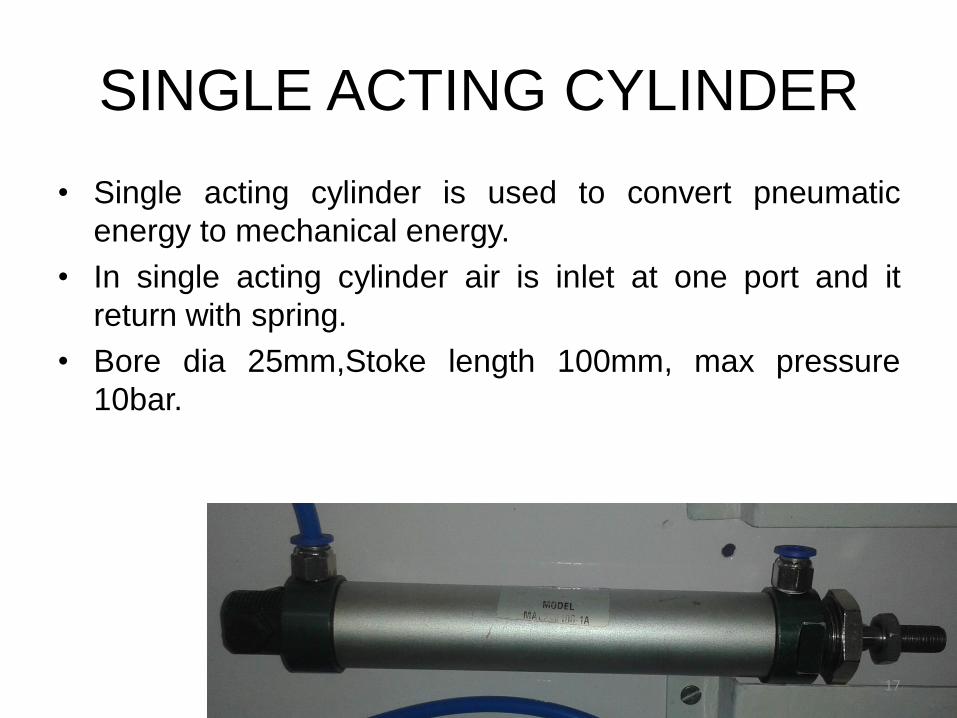
SINGLE ACTING CYLINDER
• Single acting cylinder is used to convert pneumatic
energy to mechanical energy.
• In single acting cylinder air is inlet at one port and it
return with spring.
• Bore dia 25mm,Stoke length 100mm, max pressure
10bar.
17
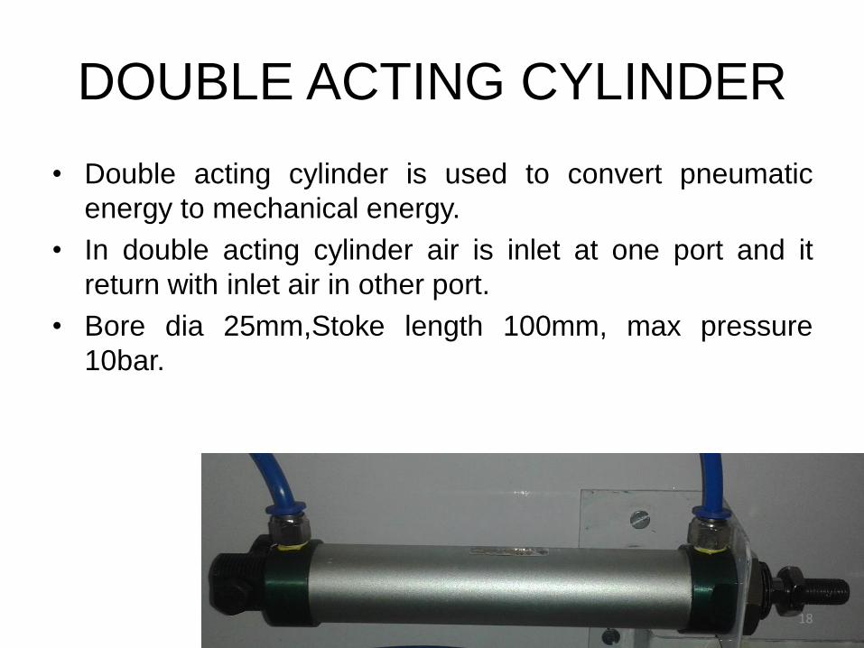
DOUBLE ACTING CYLINDER
• Double acting cylinder is used to convert pneumatic
energy to mechanical energy.
• In double acting cylinder air is inlet at one port and it
return with inlet air in other port.
• Bore dia 25mm,Stoke length 100mm, max pressure
10bar.
18

LIMIT SWITCHES NC/NO
• Limit switches is used to control the stoke length of
single or double acting cylinder.
19
PROXIMITY SENSOR
• Proximity sensor is also used to control the stoke length
of cylinder.
• Silencer is used to reduce the noise of outlet of air.SILENCER
20

3/2 WAY SINGLE SOLENOID VALVE
• 3/2-way single solenoid valve, normally closed.
• When the voltage(12v) is applied the function plate is
move and P port is connected with the silencer.
• It is spring return when signal is cut off.
21
5/2 WAY SINGLE SOLENOID
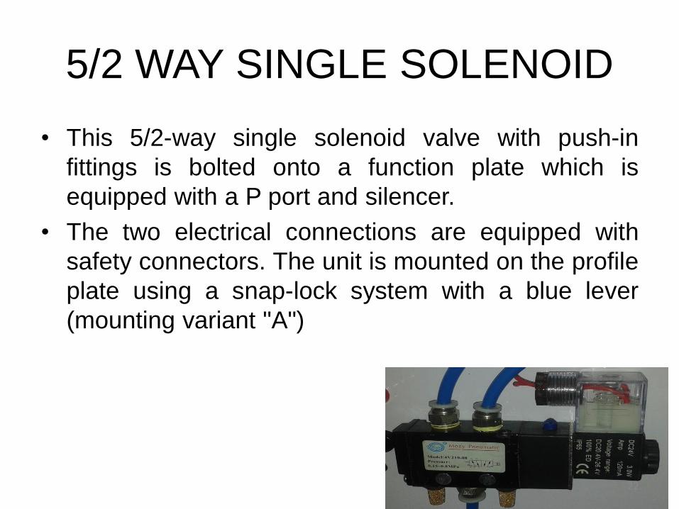
• This 5/2-way single solenoid valve with push-in
fittings is bolted onto a function plate which is
equipped with a P port and silencer.
• The two electrical connections are equipped with
safety connectors. The unit is mounted on the profile
plate using a snap-lock system with a blue lever
(mounting variant "A")
22

5/2 WAY DOUBLE SOLENOID
• 5/2 way double solenoid control valve is open or closed
with double solenoid on or off.
23
AURDINO CONTROLLER
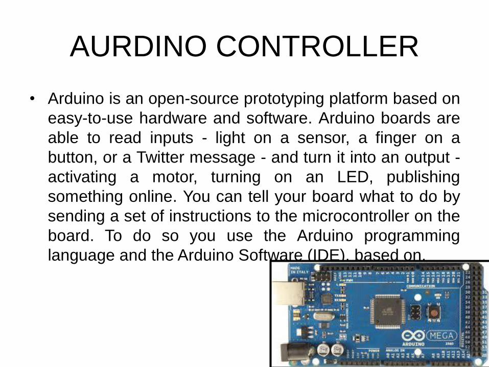
• Arduino is an open-source prototyping platform based on
easy-to-use hardware and software. Arduino boards are
able to read inputs - light on a sensor, a finger on a
button, or a Twitter message - and turn it into an output -
activating a motor, turning on an LED, publishing
something online. You can tell your board what to do by
sending a set of instructions to the microcontroller on the
board. To do so you use the Arduino programming
language and the Arduino Software (IDE), based on.
24

PICK UP ROLL AND SS ROD
• The material of the pick-up roll is rubber. The pick-up roll
is mounted on S.S rod. The pick-up rolls have high co-
efficient of friction, so they pull the paper from the paper
roll.
• The stainless steel rod is used for to support and rotated
pick-up roll. The s.s rod is rotated with help of high
torque 200rpm D.C motor .The s s rod is supported by
the ball bearing at end of the s s rod
25

CIRCUIT DIAGRAM
• How to Operate Single acting cylinder with 3/2 single
solenoid control valve.?
26

• How to Operate Double acting cylinder with 5/2
single solenoid control valve.?
27

• How to Operate Double acting cylinder with 5/2 single solenoid control valve.?
28
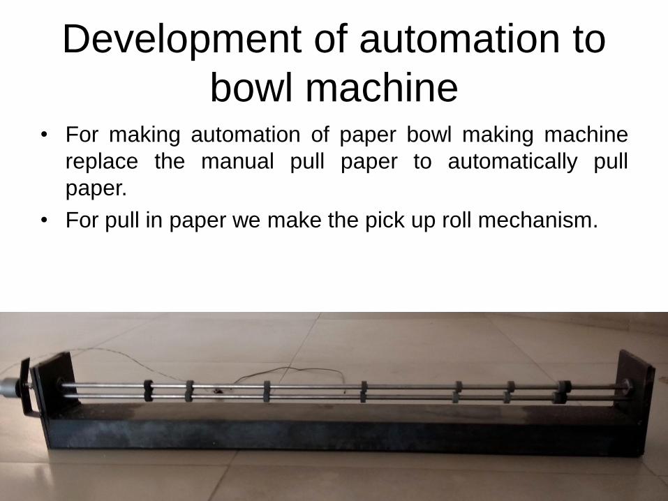
Development of automation to
bowl machine • For making automation of paper bowl making machine
replace the manual pull paper to automatically pull
paper.
• For pull in paper we make the pick up roll mechanism.
29
CONCLUSION
• On completion of this project, we have learned how to:
• 1. Read and understand pneumatic circuit diagrams and
to recognize international standards.
• 2. Recognize electrical components and understand their
functions.
• 3. Construct simple electro-pneumatic circuits.
• 4. Read and understand circuit diagrams for electro-
pneumatic controls.
• 5. Design circuits for the control of multi-actuator
systems.
• 6. Understand the function, design, technical data and
symbols for electronic sensors.
• 7. Include timer functions in control circuits. 30

REFERENCES
• Designing and Fabrication of Electro-Pneumatic Trainer Kit Kanwar J.S Gill, RoshanKumar, Sushil Kumar Department ofMechanical Engineering, Gulzar Group ofInstitutes, Ludhiana, Punjab, India
• Published in L.M. Camarinha-Matos, HamidehAfsarmanesh, Heinz-H. Erbe (Ed): Advances inNetworked Enterprises, Kluwer, 2000, pp 249-258
31

Thank you
32