
Development of an Automated Impact Hammer for Modal ... · UNCLASSIFIED Development of an Automated...
33
UNCLASSIFIED Development of an Automated Impact Hammer for Modal Analysis of Structures P. E. Norman, G. Jung, C. Ratcliffe, R. Crane and C. Davis Air Vehicles Division Defence Science and Technology Organisation DSTO–TN–1062 ABSTRACT This report outlines the development and testing of a prototype compact au- tomated impact hammer designed to be surface mounted on a structure to pro- vide an impulse-based structural excitation source for vibration testing. The automated device was designed to be integrated with a distributed fibre optic sensing system which measures the in-plane dynamic strain of the structure at a spatially dense grid of sensing points. The hammer was tested on a compos- ite plate with induced damage and the excitation and response data were used to generate complex curvature shapes for the plate. These data were in turn used with a structural health monitoring tool known as iSIDER that detects anomalies in complex operating curvature shapes to locate damage and other areas with structural stiffness variations. The impactor was shown to repli- cate the functionality of a modally tuned impact hammer that had been used previously. The analysed data correctly identified the impact damage location using a fully automated routine. APPROVED FOR PUBLIC RELEASE UNCLASSIFIED
Transcript of Development of an Automated Impact Hammer for Modal ... · UNCLASSIFIED Development of an Automated...

UNCLASSIFIED
Development of an Automated Impact Hammer
for Modal Analysis of Structures
P. E. Norman, G. Jung, C. Ratcliffe, R. Crane andC. Davis
Air Vehicles Division
Defence Science and Technology Organisation
DSTO–TN–1062
ABSTRACT
This report outlines the development and testing of a prototype compact au-tomated impact hammer designed to be surface mounted on a structure to pro-vide an impulse-based structural excitation source for vibration testing. Theautomated device was designed to be integrated with a distributed fibre opticsensing system which measures the in-plane dynamic strain of the structure ata spatially dense grid of sensing points. The hammer was tested on a compos-ite plate with induced damage and the excitation and response data were usedto generate complex curvature shapes for the plate. These data were in turnused with a structural health monitoring tool known as iSIDER that detectsanomalies in complex operating curvature shapes to locate damage and otherareas with structural stiffness variations. The impactor was shown to repli-cate the functionality of a modally tuned impact hammer that had been usedpreviously. The analysed data correctly identified the impact damage locationusing a fully automated routine.
APPROVED FOR PUBLIC RELEASE
UNCLASSIFIED

DSTO–TN–1062 UNCLASSIFIED
Published by
DSTO Defence Science and Technology Organisation506 Lorimer St,Fishermans Bend, Victoria 3207, Australia
Telephone: (03) 9626 7000Facsimile: (03) 9626 7999
© Commonwealth of Australia 2012AR No. 015-205February, 2012
APPROVED FOR PUBLIC RELEASE
ii UNCLASSIFIED

UNCLASSIFIED DSTO–TN–1062
Development of an Automated Impact Hammer for ModalAnalysis of Structures
Executive Summary
This report outlines the development and testing of a prototype compact automated im-pact hammer designed to be surface mounted on a structure to provide an impulse-basedstructural excitation source for vibration testing. The automated device was designed tobe integrated with a distributed fibre optic sensing system which measures the in-planedynamic strain response of the structure across a spatially dense grid of sensing points.
The work described in this report forms part of a contribution by DSTO to a re-search program on Structural Health Monitoring Through Environmental Excitation andOptical Fibre Sensors sponsored by the Office of Naval Research (ONR) under a NavalInternational Cooperative Opportunities in Science and Technology Program (NICOP).It is a collaborative research effort involving researchers from the US Naval Academy(USNA), Naval Surface Warfare Centre – Carderock Division (NSWCCD), the AustralianCo-operative Research Centre for Advanced Composite Structures (CRCACS) and DSTO.
The ultimate goal of the three year research program is the demonstration and valida-tion of a large area vibration-based structural health monitoring system on a large com-posite sub-structure using simulated environmental excitation and a network of surface-mounted fibre Bragg gratings for response measurement. This report documents an al-ternative excitation methodology which may be used as part of the structural healthmonitoring system in the absence of suitable environmental excitation.
UNCLASSIFIED iii

DSTO–TN–1062 UNCLASSIFIED
THIS PAGE IS INTENTIONALLY BLANK
iv UNCLASSIFIED

UNCLASSIFIED DSTO–TN–1062
Contents
1 Background 1
1.1 Experimental modal analysis . . . . . . . . . . . . . . . . . . . . . . . . . 1
1.2 SIDER . . . . . . . . . . . . . . . . . . . . . . . . . . . . . . . . . . . . . 1
2 Introduction 2
3 Development 3
3.1 Impact tip . . . . . . . . . . . . . . . . . . . . . . . . . . . . . . . . . . . 3
3.2 Actuator . . . . . . . . . . . . . . . . . . . . . . . . . . . . . . . . . . . . 3
3.3 Control circuit . . . . . . . . . . . . . . . . . . . . . . . . . . . . . . . . . 5
3.4 Housing . . . . . . . . . . . . . . . . . . . . . . . . . . . . . . . . . . . . . 6
3.5 Integration with FBG interrogation system . . . . . . . . . . . . . . . . . 7
4 Experimental validation 9
5 Conclusions 11
6 Acknowledgements 12
References 13
Appendices
A Operation 15
A.1 Specifications . . . . . . . . . . . . . . . . . . . . . . . . . . . . . . . . . . 15
A.2 Set-up optimisation . . . . . . . . . . . . . . . . . . . . . . . . . . . . . . 15
B Control circuit schematic 17
C Control circuit code 18
D Housing component drawings 20
UNCLASSIFIED v

DSTO–TN–1062 UNCLASSIFIED
THIS PAGE IS INTENTIONALLY BLANK
vi UNCLASSIFIED

UNCLASSIFIED DSTO–TN–1062
1 Background
1.1 Experimental modal analysis
Experimental modal analysis involves the study of the dynamic characteristics of a me-chanical structure. The goal of modal analysis is to determine the natural frequencies,mode shapes and modal damping of an object or structure, which can be used for a widevariety of applications. The study of changes to or anomalies in the modal characteristicscan sometimes be used as a diagnostic tool for health monitoring.
The testing method used to acquire the data for a modal analysis involves the mea-surement and analysis of the vibrational response at a series of locations on the structureto some applied excitation force. Typically, the response of the structure is measured withaccelerometers or a non-contact laser vibrometer and a piezoelectric-based force trans-ducer is used to measure the excitation force. With the input excitation and structuralresponse known, a frequency response function (FRF) between the pairs of excitation andresponse points can be calculated. An FRF is the transfer function of a linear system anddefines the spectrum of the system output relative to the excitation input. Commonlyused continuous excitation sources include electrodynamic shakers and servo-hydraulicsystems; alternatively, modally tuned hammers provide an impulsive excitation. In thecase of broadband noise and swept sine signals, an electrodynamic shaker can be coupledto the structure and used as the excitation source. In the case of impulse excitation, theaim is to have an input with energy at all frequencies in the frequency range of interest.This could be achieved with a perfect impulse with an infinitesimally small duration andinfinitely large magnitude. However, an approximation to this can be achieved with amodal impact hammer which imparts a pulse that is approximately a half-sine.
A modal impact hammer is an impactor designed to impart a pulse with a very shortduration in order to achieve approximately constant excitation energy in the frequencyrange of interest. A load cell is incorporated behind the tip of the hammer in order torecord the waveform of the exciting force, which is necessary to calculate the FRF.
1.2 SIDER
SIDER (Structural Irregularity and Damage Evaluation Routine) is a broadband vibration-based method for locating areas of structural stiffness variation and/or potential damageby looking at features in the complex Operating Curvature Shapes (OCS) of vibratingstructures. SIDER was developed by researchers at the US Naval Surface Warfare Center– Carderock Division (NSWCCD) and the US Naval Academy (USNA) for the inspectionof large-scale composite structures which are difficult and time consuming to inspect usingconventional inspection methods [1].
In order to identify areas of structural stiffness variations with SIDER, a set of ex-perimental OCS must be determined for the structure under inspection. These OCS canbe obtained from a set of FRFs measured with a digital spectrum analyser for a grid oftest points on the structure. The original SIDER process involved a “roving hammer”approach where an impact excitation is applied with an instrumented hammer across a
UNCLASSIFIED 1

DSTO–TN–1062 UNCLASSIFIED
dense grid of excitation points while the structural response is measured by accelerometersat small number of fixed locations. This method allows for the OCS to be mapped with aspatially dense resolution without the requirement for a large number of sensors and theassociated cabling and instrumentation hardware. The drawback with this arrangementis that multiple-point excitation is not feasible for in-service structural monitoring.
It is therefore desirable to modify the SIDER methodology to a “roving response”approach such that a dense measurement grid is used with only a few excitation points, orideally environmental excitation. The number of sensors required to achieve this rendersthe use of accelerometers impractical, so the measurement grid is achieved via the useof distributed Fibre Bragg Gratings (FBGs) in optical fibres. The modified approach toSIDER has been given the name iSIDER or inverse SIDER to reflect the fact that theprocedure acquires data in an inverse way, such that excitation of the structure occurs ata fixed reference location, where the response is measured at many locations using a largearray of surface mounted FBG strain sensors [2].
FBGs are ideally suited to the roving response approach as multiple gratings canbe written onto the same optical fibre which allows distributed strain sensing of largestructures using a minimal number of optical fibres. Additionally, FBGs are immune toelectromagnetic interference, are inherently corrosion-resistant and their size and weightallow them to be incorporated into or onto composite structures with minimal intrusion.
2 Introduction
The idea of an automated hammer was conceived to meet several objectives: (i) to repli-cate the excitation characteristics of a manual hammer; (ii) to reduce the manual effortassociated with the repetitive approach; and (iii) by eliminating the variability inherent inmanually applied hammer excitation, to improve the data quality for iSIDER tests whenusing single-point excitation with a distributed Fibre Bragg Grating (FBG) interrogationsystem for multiple point response measurement.
Commercially available FBG interrogation systems do not have sufficient frequencybandwidth or strain resolution to acquire structural vibration data of satisfactory fidelityfor this project. Therefore, an in-house system [3] was developed by researchers at DSTOto overcome these problems. However, one drawback of the system was that only onegrating could be interrogated at a time, rather than the preferred simultaneous interroga-tion of all the gratings. Consequently the reference excitation point had to be impactedseparately for each of the FBGs in the grid. This requirement had the potential to intro-duce variability in the procedure since it is difficult to reproduce precisely the dynamicforce and location of a manual hammer impact. It was therefore desirable to producean automated method of exciting a structure that could provide repeatable impacts thatcoupled energy into the structure across the required frequency range, and which wouldalso apply the impacts at precisely the same location. In addition, the device was requiredto integrate with the existing FBG interrogation system so that the excitation triggeringand response measurement could be fully automated.
2 UNCLASSIFIED

UNCLASSIFIED DSTO–TN–1062
3 Development
The four main elements considered in the design of the automated impact hammer were:an actuator to generate the force for the impact; an impact tip; a control circuit to drivethe actuator; and a housing to protect and support the various components above thestructure under test. The details relating to each element of the design are outlined in theproceeding sections.
3.1 Impact tip
As already mentioned, the purpose of the automated impactor was to replace the manualinstrumented hammer previously used for iSIDER testing. As such, it was desirable thatthe impact generated by the automated hammer be as similar as possible to that of themanual hammer, both in magnitude and waveform. The manual hammer previously usedhad a set of removable screw-in impact tips, however they were not compatible with theload cells available for use with the automated hammer. Therefore some new impacttips and housings (Figure 1) were designed. The impact tip housing was machined inaluminium with a screw-thread that could be assembled into the existing load-cells andwith a recessed area to hold the impact tip with an interference fit. Tips were machinedin both Teflon and Nylon with a similar shape to the manual hammer tip. Teflon andNylon were chosen because of their availability and because they have similar stiffnesscharacteristics to the tips provided with the manual modal hammer.
Impact tip housing (aluminium)
Impact tip(Teflon or Nylon)
Figure 1: Impact housing and tip
3.2 Actuator
The aim of the actuator in this design was to accelerate the tip such that it impactsthe structure with a repeatable force that can be varied as needed. It was determinedthat a DC solenoid would provide an effective means to generate repeatable impacts withvariable force control. When the solenoid is energised it creates an electromagnetic fieldthat causes the ferrous core mass to accelerate. The kinetic energy of the core at themoment just before the tip impacts the structure will determine the force level generated.When the solenoid is energised by a constant voltage supply, the maximum speed (impactforce) is achieved if the solenoid remains energised, and thus keeps accelerating, right upuntil the tip reaches the surface. The acceleration of the core mass is related to the forceexerted on it. The force is, in turn, determined by the voltage with which the solenoid isenergised, thus a higher voltage increases the maximum force achievable. Consequently,the force of an impact is directly determined by the excitation voltage and duration ofsolenoid excitation (or solenoid excitation pulse-width). Some variability in the applied
UNCLASSIFIED 3

DSTO–TN–1062 UNCLASSIFIED
force due to friction in the system is to be expected, however testing showed that theimpact force was more repeatable than that obtained with the manual hammer excitation.Hence the solenoid is capable of giving a reasonably repeatable impact (Figure 2) with theforce adjustable by varying the excitation voltage and pulse-width. Power for the solenoidcan be supplied either from mains or with a portable battery pack and preliminary testingwith a 12 volts (continuous) rated solenoid indicated that appropriate impacts could begenerated with a power supply in the range of 12–35 volts.
0 2 4 0 2 4 0 2 4 0 2 4-20
0
50
100
150
200
250
Forc
e (N
)
Time (ms)
Automated hammer load cell trace
Figure 2: Impact repeatability – trace recorded from load cell
One challenge in adapting a solenoid for actuation was finding a way to interface themoving core with a load cell and impact tip. Push-type solenoids of the desired sizegenerally only had a narrow tip protruding from the base. To attach a load-cell wouldrequire significant modification so it was decided that a pull-type solenoid would be abetter solution. In this type of solenoid, the base could be easily drilled out and anextension piece inserted into to the solenoid core. Using this configuration it was alsopossible to insert a spring inside the solenoid encircling the extension piece to facilitatereturn of the core to its starting point after an impact. The extension piece was designedsuch that a load-cell could be screwed onto the end, which protruded beneath the solenoidas shown in Figure 3.
4 UNCLASSIFIED

UNCLASSIFIED DSTO–TN–1062
Solenoid core
Solenoid
Extension piece
Load cell
Impact tip
Figure 3: Solenoid assembly
3.3 Control circuit
To generate an impact the solenoid needs to be driven by an excitation voltage with ashort period to accelerate the core and tip toward the structure. Testing was conducted todetermine a suitable pulse duration and amplitude to deliver a single impact comparableto that of the manual hammer. The outcome of this testing indicated that the ideal voltagelevel ranged from 15 to 35 volts and the ideal pulse length was dependent on the distancebetween the impactor tip and the surface of the structure under test. It was found thatin order to deliver a strong enough impact to induce a reasonable structural responsewithout a double-hit that the pulse should end just before the tip of the impactor makescontact with the surface. The pulse length, typically in the range of tens of milliseconds,could be determined for each individual set-up by observing the synchronous time tracesof the driving pulse next to the response from the impactor load-cell. The pulse length wasadjusted such that the trailing edge occurred just before the load cell indicated contact ofthe tip (Appendix A.2).
A small electric circuit designed to drive the solenoid was fixed inside the impactorhousing. The intention was that the circuit would deliver a pulse of variable pre-set lengthwhen an external trigger pulse was delivered from a computer parallel port (or other TTL-level device). Initially, an analogue pulse-generation circuit was prototyped using a one-shot monostable multivibrator. The pulse length could be adjusted with a potentiometerand the resulting pulse would switch a transistor delivering high voltage (∼35 volts) tothe solenoid. This set-up was tested successfully with the FBG interrogation system.
UNCLASSIFIED 5

DSTO–TN–1062 UNCLASSIFIED
Programming header
Isolated output (Optional, requires 5V)
BCD switches(Hex coded)
(High)
(Low)
(Optional)Switched Output (Tied to + Power)
Power (15 to 40V)
Isolated trigger in(1.8-10mA LED)
Pic16F690 Micro
5V Voltage regulator
Status LED
(+)(-)
(-)(+)
(+)(-)
FET switch
(-)(Out)
(+)
Figure 4: Impactor control circuit
During the electronic integration process, the drive circuit was re-designed (Figure 4)to incorporate a digitally controlled pulse generator which provided greater controllabilityof the pulse adjustment. An opto-isolated trigger input to a PIC16F690 microcontrollergenerates a pulse of 0.5 – 128 ms duration which can be set with a pair of 4-bit rotaryswitches. The pulse generated by the microcontroller activates a FET switch to deliverpower to the solenoid. The redesigned drive circuit requires only a single power supply ofbetween 9 and 50 volts to drive the solenoid and it can be triggered using an ordinary PCparallel port or other similar TTL-level source.
3.4 Housing
The housing of the automated impact hammer is designed to contain the actuator andall of the necessary drive circuitry. The only connectors exterior to the housing are forthe power supply, the trigger signal and transmitting the force data (from the load cell).The digital switches for adjusting the pulse duration are accessible from the exterior ofthe structure via a pair of small holes into which a small screwdriver can be inserted.
The housing allows for the height of the impactor above the structure to be adjusted.This enables compensation for variability in the system which may arise from the use ofdifferent springs, impact tips or load cells. Four levelling feet support the housing and canbe individually adjusted to accommodate surfaces that are not completely flat (see Figure5).
Another design consideration for the housing was the weight of the entire assembly.The heavier the assembly, the more likely it is to change the dynamic characteristics of
6 UNCLASSIFIED

UNCLASSIFIED DSTO–TN–1062
the structure under test. At the same time, if the housing is too light the reaction forcefrom the solenoid will cause it to recoil from the surface. An early prototype housingdesign showed significant recoil from the structure at the force levels required. The finalhousing was constructed to be heavier (from 6 mm thick aluminium), to reduce the chanceof recoil. Typically, the iSIDER results adjacent to the excitation location are excludedfrom the analysis. However, further testing remains to be completed on the mass-loadingeffects of this device for modal testing on different structures.
Figure 5: Housing design showing solenoid actuator and control circuit PCB
3.5 Integration with FBG interrogation system
The automated impact hammer was designed to be integrated into a previously developedFBG interrogation system described in [3]. The system uses a tuneable laser source toselect individual gratings and a photodiode connected to a frequency analyser to measurethe dynamic response. The system had previously been configured to interrogate gratingswith sustained excitation by a shaker, or impulse excitation by an instrumented hammer.The system set-up for impulse excitation required human involvement during a test bothto operate the hammer and to save the individual data sets using the frequency analyser.The new device removes the requirement for manual operation of the hammer, but forfully autonomous operation the data acquisition also required automation. The datacould not be saved automatically by the frequency analyser when operated in real-timeanalysis mode. However, autonomous acquisition could be achieved by configuring theanalyser as a waveform recorder which could be instructed to begin recording by theFBG switching system. This was done previously when shaker excitation was used, andthe frequency analysis could be performed by processing data after completion of thetest. As operating the system with automated hammer excitation would be similar tooperating with shaker excitation, the shaker excitation configuration was used with somemodifications to accommodate a trigger signal for the hammer (see Figure 6).
UNCLASSIFIED 7

DSTO–TN–1062 UNCLASSIFIED
OF Switch 2
OF Switch 1
Photodiode 2
GPIB/USB
SIDER Analysis/FBG interrogation
control
Tuneable LaserPower meterLaser O/P
λ1 λ2 λn
λ1 λ2 λn
λ1 λ2 λn
Structure under test
OF Coupler
Photocurrent to voltage conversion
Frequency Analyser ExtTrig
Trig analyser
Trig impacter
GPIB
USB
Analogue (Coax)
Optical Fibre
Digital (PCMCIA)
Trigger lines
Figure 6: Diagram showing modified interrogation set-up to incorporate automatedimpactor and response measurement
In the previous configuration, a single trigger signal had already been implemented toinstruct the frequency analyser to begin recording once the tuneable laser had selecteda sensor. In order to integrate the automated impactor, a second trigger channel wasadded and set-up to send a number of pulses, with a pre-set delay between each, after thefrequency analyser was instructed to start. With this second trigger channel connected tothe trigger input of the automated impactor, the system can coordinate a series of impactsafter the frequency analyser begins recording for each grating. A schematic timing diagramis shown in Figure 7 to illustrate the modified external trigger implementation where theauto-impactor is configured to impact twice for each grating. The number of impacts foreach grating is user configurable depending on the application.
8 UNCLASSIFIED

UNCLASSIFIED DSTO–TN–1062
Time (not to scale)
Laser Switching Trigger Freq Analyser Analyser Recording Trigger Auto Hammer
Figure 7: Illustration of modified external trigger implementation
4 Experimental validation
The iSIDER routine was used to inspect a glass fibre test panel with a quasi-isotropic lay-up in E-glass/vinyl ester (1.32 m [52”] long, 0.81 m [32”] wide, & 6 mm [1/4”] thick). Priorto the inspection the test panel was damaged in two areas with different impact energylevels, 68 J (48.8 ft-lb) and 108 J (76.3 ft-lb). A set of 10 optical fibres each containing 10FBG sensors spaced at 50.8 mm (2 inch) intervals was adhered to the surface of the plateusing Kapton® self-adhesive pressure-sensitive tape. The panel was laid horizontal on twolayers of bubble wrap supported on a large table as shown in Figure 8. The initial iSIDERinspection used a manual instrumented hammer to excite the structure and the responsewas measured for each of the FBGs. FRFs were obtained then analysed using the iSIDERalgorithm, which first generates frequency dependent OCS from the FRFs and then looksfor anomalies in the OCS. These anomalies are represented by an irregularity index whichis presented graphically as a contour plot overlaid on a diagram of the structure. Boththe heavy and light damage areas could be located using the manual hammer method asindicated by the contour map shown in Figure 9.
UNCLASSIFIED 9

DSTO–TN–1062 UNCLASSIFIED
Figure 8: Impactor on a composite plate supported by bubble wrap
108 J impact
68 J impact
Figure 9: iSIDER analysis of manual hammer data
Experimental validation of the automated impact hammer was performed by usingthe same test article and substituting the manually operated modal hammer with theautomated impact hammer and the FBG interrogation system. For this test, the FBGsensors were positioned to interrogate the plate only in the region containing the heavyimpact site. At the time of testing, the housing and integrated drive circuitry had not yetbeen completed, so a bench-top digital function generator was used to produce a squarepulse which controlled a prototype drive circuit, and the impact assembly was mounted
10 UNCLASSIFIED

UNCLASSIFIED DSTO–TN–1062
on the structure using a temporary housing arrangement. Using the same methodology asfor the manual hammer testing, the panel was excited and the response recorded for eachFBG sensor. This was done with the automated hammer assembly positioned at each ofthe four reference points where the manual hammer was used.
As with the manual hammer method, the automated impactor iSIDER results wereplotted on a contour map as shown in Figure 10.
108 J impact
Figure 10: iSIDER analysis of automated impactor data
The contour map shows a clearly identifiable feature that is near the heavy damagelocation on the plate as was seen for the manual hammer excitation on the same plate.This result shows that the automated impactor can be successfully used with iSIDERas an alternative to manual hammer or environmental excitation. Further testing is rec-ommended to compare the relative effectiveness of the different excitation techniques indetecting damage using the iSIDER routine.
5 Conclusions
A prototype compact automated impact hammer has been designed for surface mountingon structures to provide an impulse-based structural excitation source for vibration testing.Accompanying hardware and software were developed to facilitate the automation andcontrol of the excitation impulse magnitude and duration and to interface the excitationsource with a network of FBG sensors for response measurement of the structure undertest. The ability of the automated impactor to replace a manually operated instrumentedimpact hammer was validated by conducting an iSIDER analysis on an impact damagedcomposite panel using both excitation methodologies. Both iSIDER analyses, conductedusing manual and automated excitation, showed a large feature near the damage location.
The results from preliminary testing of the automated impact hammer are promisingand suggest that the device can provide a satisfactory alternative excitation methodologyfor iSIDER where a suitable environmental excitation is not available. However, it should
UNCLASSIFIED 11

DSTO–TN–1062 UNCLASSIFIED
be noted that the prototype device was designed to impart a relatively low impact energyand is therefore only suitable for application to small structures. A redesign of the actuator,impact tip and housing would be required to induce the energy levels appropriate for large-scale structural excitation.
6 Acknowledgements
The authors gratefully acknowledge the Office of Naval Research for the support of thiswork under the Naval International Cooperative Opportunities in Science and TechnologyProgram (Grant No. N00014-09-1-0364; program sponsor Dr. Ignacio Perez). The authorsalso thank Chris Rider (DSTO) for advice relating to the impactor tip design and loadcell integration and Anthony Rizk for assistance with the experimental validation.
12 UNCLASSIFIED

UNCLASSIFIED DSTO–TN–1062
References1. Colin P. Ratcliffe, Roger M. Crane, John W. Gillespie, Jr., “Damage Detection In
Large Composite Structures Using A Broadband Vibration Method”, Journal of TheBritish Institute of Non-Destructive Testing, Insight, Volume 46, pages 10-16, (2004).
2. Roger Crane, Colin Ratcliffe, Claire Davis, Patrick Norman, and Anthony Rizk,NSWCCD-65-TR-2011/20, “Development of the iSIDER Inspection Method UsingBragg Gratings to Identify Impact Damage in Composite Plates”, (2011).
3. P.E. Norman and C.E. Davis, Technical report DSTO-TR-2370, Defence Scienceand Technology Organisation (DSTO) Australia, “An intensity-based demodulationapproach for the measurement of strains induced by structural vibrations using Bragggratings”, (2009).
UNCLASSIFIED 13

DSTO–TN–1062 UNCLASSIFIED
14 UNCLASSIFIED

UNCLASSIFIED DSTO–TN–1062
Appendix A Operation
A.1 Specifications
Supply voltageRecommended 12 – 40 V
Limits 9 – 50 V
Max. switching currentPulse (100 ms) 10 A
Continuous 3 A
Trigger
Min. current 1.8 mA
Min. duration 1 ms
Latency 1 ms
Output pulseRange 0.5 - 128 ms
Resolution 0.5 ms
Typical operationVoltage 35 V
Pulse length 10-15 ms
A.2 Set-up optimisation
To achieve an optimum hit for a given supply voltage the solenoid should remain energiseduntil the moment before the impact tip makes contact with the surface of a structure. Thefollowing steps detail the procedure to optimise the drive circuit pulse length to achievethis:
1. Connect the supply voltage line to a power supply.
2. Connect the load-cell to a digital frequency analyser/data acquisition system.
3. Connect the trigger line to a trigger source (control laptop) and using a T/Y-connector, also connect it to a second channel on the frequency analyser/data ac-quisition system.
4. Configure the data acquisition system to display the traces of both the load-celloutput and the trigger-line output (set the acquisition to trigger from a rising edgeon the trigger-line).
5. Set the desired supply voltage (15-35 V recommended), and set the pulse length tothe shortest possible.
6. Using the control laptop, trigger the impactor. Nothing should happen.
7. Increase the duration one step at a time using the rotary switches accessible fromthe housing, triggering the impactor after each increase. Observe that the impact tipbegins to move. Continue increasing the pulse duration and triggering the impactor
UNCLASSIFIED 15

DSTO–TN–1062 UNCLASSIFIED
until an impact occurs and the load-cell response appears on the acquisition systemdisplay.
Pulse length tuning
-200
20406080
100120140160180200220240
-5 0 5 10 15 20 25 30 35
Time (ms)
Forc
e (N
)
-0.200.20.40.60.811.21.41.61.822.22.4
Trig
ger (
V)
Load Cell (N) Trigger (V)
Drive pulse duration. Pulse begins up to 1 ms after the rising edge of the trigger.
Figure A1: Tuning the pulse length – the dotted line represents the solenoid drive pulsewhich initiates during the trigger pulse and terminates after the duration assigned with
the digital switches (in this example, 25 ms)
8. Observe the time between the trigger signal and the load-cell response signal (FigureA1). Ideally the length of the pulse should equal the span between the trigger andload-cell signals. However, as the pulse length is increased the tip will accelerate fora longer period so the load-cell will make contact sooner, therefore a shorter pulselength will be required.
9. Incrementally increase the pulse length and observe the converging signals until theduration is set such that the pulse ends slightly more than 1 ms before1 the load-cellsignal records contact. NOTE: The impact force will increase as the pulse duration ismade larger. It may be necessary to lower the supply voltage and repeat the processof increasing the pulse length to achieve the desired force level.
1This gap is to allow for the variable trigger latency which may be up to 1 ms
16 UNCLASSIFIED

UNCLASSIFIED DSTO–TN–1062
Appendix B Control circuit schematic
UNCLASSIFIED 17

DSTO–TN–1062 UNCLASSIFIED
Appendix C Control circuit code
’*****************************************************************
’* Name : Delay_pulse.BAS *
’* Author : George Jung *
’* Date : 19/02/2011 *
’* Version : 1.0 *
’* Notes : Firmware to control solenoid hammer pulse duration *
’* : *
’*****************************************************************
’
’ PIC16F690 Hardware connections
’
’ RA0 Prog pin
’ RA1 Prog pin
’ RA2 Trigger in/INT pin
’ RA3 MCLR (Programming pin)
’ RA4 Trig out LED
’ RA5 Indicator LED
’ RC0...7 BCD switches 1,2
’ RB4 Output for driver FET
’ RB5 NC
’ RB6 BCD switch 3
’ RB7 BCD switch 3
’
’------------Defines--------------------------
include "modedefs.bas"
define OSC 4 ’ For pause to have 0.5ms resolution!
OSCCON = %01110001 ’ 8MHz internal oscillator
OPTION_REG = %10000111
INTCON = %10010000
ANSEL = %00000000 ’ all ADC’s off
’ -----------Variables-----------------------
LED var Porta.5
TRIG var Porta.4 ’ Trigger I/P port
SW var Portb.4 ’ 8-bit BCD switch port
Delay var word
tmp2 var word
tmp3 var word
tmp var Portc
N var byte ’ loop variable
18 UNCLASSIFIED

UNCLASSIFIED DSTO–TN–1062
’--------Initialisation ----------------------
Init:
trisa = %00001100
trisb = %00010000
trisc = %11111111 ’ all port C pins are inputs
low SW
Delay = 1 ’ start with 1ms delay
on interrupt goto Delaynow
goto Start
DISABLE INTERRUPT
’ -----------ISR should go here ----------------
Delaynow:
high Trig
high SW
high LED
pause Delay
low TRIG
low LED
low SW
INTCON = $90 ’ reset interrupt flag
resume
’ --------------------------- Main code ------------------------
Start:
tmp2 = 0
tmp3 = 0
high LED ’ blink LED
Delay = tmp
pause 1
low LED
’ ---------------- Only allow interrupts in this code segment! -------
enable interrupt
for N = 1 to 200
pause 1
next N
Disable interrupt
goto Start ’ loop forever
END
UNCLASSIFIED 19

DSTO–TN–1062 UNCLASSIFIED
Appendix D Housing component drawings
80
68.00067.900
1524
3
12
3 12
22.530
34.12534.125
34.940
R3
9 X 92°2 x
4.50 THRU A
LL
M6 - 6H THRU A
LL4 x
5 THRU ALL
5 X 92°8 x
2.90 THRU A
LL 7
3
88.00087.900
100
Impactor Housing
Housing BaseW
EIGHT:
Alum
inium
SHEET 1 OF 1
NO
T TO SC
ALE
DW
G N
O.
TITLE:
REVISION
DRA
WIN
G N
OT TO
SCA
LE
MA
TERIAL:
DA
TESIG
NA
TUREN
AM
E
DEBUR A
ND
BREA
K SHARP
EDG
ES
FINISH:
UNLESS O
THERWISE SPEC
IFIED:
DIM
ENSIO
NS A
RE IN M
ILLIMETERS
SURFAC
E FINISH:
TOLERA
NC
ES: LIN
EAR:
AN
GULA
R:
Q.A
MFG
APPV
'D
CHK'D
DRA
WN
20 UNCLASSIFIED

UNCLASSIFIED DSTO–TN–1062
100
90
88.00087.800
76
5 4 x 2.050
8.350M
2.5 - 6H 7
6
Impactor Housing
Housing FrontW
EIGHT:
Alum
inium
SHEET 1 OF 1
NO
T TO SC
ALE
DW
G N
O.
TITLE:
REVISION
DRA
WIN
G N
OT TO
SCA
LE
MA
TERIAL:
DA
TESIG
NA
TUREN
AM
E
DEBUR A
ND
BREA
K SHARP
EDG
ES
FINISH:
UNLESS O
THERWISE SPEC
IFIED:
DIM
ENSIO
NS A
RE IN M
ILLIMETERS
SURFAC
E FINISH:
TOLERA
NC
ES: LIN
EAR:
AN
GULA
R:
Q.A
MFG
APPV
'D
CHK'D
DRA
WN
UNCLASSIFIED 21

DSTO–TN–1062 UNCLASSIFIED
100
90
88.00087.900
76
5
4 x 2.050
8.350 M
2.5 - 6H 7
6
Impactor Housing
Housing RearW
EIGHT:
Alum
inium
SHEET 1 OF 1
NO
T TO SC
ALE
DW
G N
O.
TITLE:
REVISION
DRA
WIN
G N
OT TO
SCA
LE
MA
TERIAL:
DA
TESIG
NA
TUREN
AM
E
DEBUR A
ND
BREA
K SHARP
EDG
ES
FINISH:
UNLESS O
THERWISE SPEC
IFIED:
DIM
ENSIO
NS A
RE IN M
ILLIMETERS
SURFAC
E FINISH:
TOLERA
NC
ES: LIN
EAR:
AN
GULA
R:
Q.A
MFG
APPV
'D
CHK'D
DRA
WN
22 UNCLASSIFIED

UNCLASSIFIED DSTO–TN–1062
90
70
54.610 14
14.680 40.640
35
15
10.200
18.550
40.630
3
2 x5
4 x 2.900 THRU A
LL 5 X 92°
56
4 x 2.050
8.350M
2.5 - 6H 7 6
Impactor Housing
Housing Side 1W
EIGHT:
Alum
inium
SHEET 1 OF 1
NO
T TO SC
ALE
DW
G N
O.
TITLE:
REVISION
DRA
WIN
G N
OT TO
SCA
LE
MA
TERIAL:
DA
TESIG
NA
TUREN
AM
E
DEBUR A
ND
BREA
K SHARP
EDG
ES
FINISH:
UNLESS O
THERWISE SPEC
IFIED:
DIM
ENSIO
NS A
RE IN M
ILLIMETERS
SURFAC
E FINISH:
TOLERA
NC
ES: LIN
EAR:
AN
GULA
R:
Q.A
MFG
APPV
'D
CHK'D
DRA
WN
UNCLASSIFIED 23
DSTO–TN–1062 UNCLASSIFIED
70
90
56
4 x 2.050
8.350M
2.5 - 6H 7
6
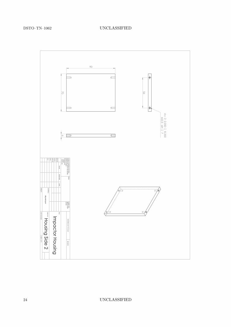
Impactor Housing
Housing Side 2W
EIGHT:
Alum
inium
SHEET 1 OF 1
NO
T TO SC
ALE
DW
G N
O.
TITLE:
REVISION
DRA
WIN
G N
OT TO
SCA
LE
MA
TERIAL:
DA
TESIG
NA
TUREN
AM
E
DEBUR A
ND
BREA
K SHARP
EDG
ES
FINISH:
UNLESS O
THERWISE SPEC
IFIED:
DIM
ENSIO
NS A
RE IN M
ILLIMETERS
SURFAC
E FINISH:
TOLERA
NC
ES: LIN
EAR:
AN
GULA
R:
Q.A
MFG
APPV
'D
CHK'D
DRA
WN
24 UNCLASSIFIED

UNCLASSIFIED DSTO–TN–1062
3
12
12
3
R3
M3 - 6H THRU A
LL 2.500
THRU ALL
5 X 92°8 x
2.900 THRU A
LL
100
88.00087.900
68.00067.900
80
Impactor Housing
Housing TopW
EIGHT:
Alum
inium
SHEET 1 OF 1
NO
T TO SC
ALE
DW
G N
O.
TITLE:
REVISION
DRA
WIN
G N
OT TO
SCA
LE
MA
TERIAL:
DA
TESIG
NA
TUREN
AM
E
DEBUR A
ND
BREA
K SHARP
EDG
ES
FINISH:
UNLESS O
THERWISE SPEC
IFIED:
DIM
ENSIO
NS A
RE IN M
ILLIMETERS
SURFAC
E FINISH:
TOLERA
NC
ES: LIN
EAR:
AN
GULA
R:
Q.A
MFG
APPV
'D
CHK'D
DRA
WN
UNCLASSIFIED 25

DSTO–TN–1062 UNCLASSIFIED
1612
20
14
M3 M
achine Threads
2.8
R1.4
Impactor Housing
Rotation BlockW
EIGHT:
Alum
inium
SHEET 1 OF 1
NO
T TO SC
ALE
DW
G N
O.
TITLE:
REVISION
DRA
WIN
G N
OT TO
SCA
LE
MA
TERIAL:
DA
TESIG
NA
TUREN
AM
E
DEBUR A
ND
BREA
K SHARP
EDG
ES
FINISH:
UNLESS O
THERWISE SPEC
IFIED:
DIM
ENSIO
NS A
RE IN M
ILLIMETERS
SURFAC
E FINISH:
TOLERA
NC
ES: LIN
EAR:
AN
GULA
R:
Q.A
MFG
APPV
'D
CHK'D
DRA
WN
26 UNCLASSIFIED

Page classification: UNCLASSIFIED
DEFENCE SCIENCE AND TECHNOLOGY ORGANISATIONDOCUMENT CONTROL DATA
1. CAVEAT/PRIVACY MARKING
2. TITLE
Development of an Automated Impact Hammerfor Modal Analysis of Structures
3. SECURITY CLASSIFICATION
Document (U)Title (U)Abstract (U)
4. AUTHORS
P. E. Norman, G. Jung, C. Ratcliffe, R. Crane andC. Davis
5. CORPORATE AUTHOR
Defence Science and Technology Organisation506 Lorimer St,Fishermans Bend, Victoria 3207, Australia
6a. DSTO NUMBER
DSTO–TN–10626b. AR NUMBER
015-2056c. TYPE OF REPORT
Technical Note7. DOCUMENT DATE
February, 2012
8. FILE NUMBER
2011/1237193/19. TASK NUMBER
LRR 07/25010. TASK SPONSOR
AVD11. No. OF PAGES
2612. No. OF REFS
3
13. URL OF ELECTRONIC VERSION
http://www.dsto.defence.gov.au/
publications/scientific.php
14. RELEASE AUTHORITY
Chief, Air Vehicles Division
15. SECONDARY RELEASE STATEMENT OF THIS DOCUMENT
Approved for Public Release
OVERSEAS ENQUIRIES OUTSIDE STATED LIMITATIONS SHOULD BE REFERRED THROUGH DOCUMENT EXCHANGE, PO BOX 1500,EDINBURGH, SOUTH AUSTRALIA 5111
16. DELIBERATE ANNOUNCEMENT
No Limitations
17. CITATION IN OTHER DOCUMENTS
No Limitations
18. DSTO RESEARCH LIBRARY THESAURUS
Vibration Analysis Bragg gratingImpact Structural Health MonitoringModal hammer Dynamic characteristics
19. ABSTRACT
This report outlines the development and testing of a prototype compact automated impact hammerdesigned to be surface mounted on a structure to provide an impulse-based structural excitation sourcefor vibration testing. The automated device was designed to be integrated with a distributed fibre opticsensing system which measures the in-plane dynamic strain of the structure at a spatially dense grid ofsensing points. The hammer was tested on a composite plate with induced damage and the excitationand response data were used to generate complex curvature shapes for the plate. These data were inturn used with a structural health monitoring tool known as iSIDER that detects anomalies in complexoperating curvature shapes to locate damage and other areas with structural stiffness variations. Theimpactor was shown to replicate the functionality of a modally tuned impact hammer that had beenused previously. The analysed data correctly identified the impact damage location using a fullyautomated routine.
Page classification: UNCLASSIFIED