Development of an Assistive Motorized Hip...
5
Development of an Assistive Motorized Hip Orthosis Kinematics Analysis and Mechanical Design Jeremy Olivier, Mohamed Bouri, Amalric Ortlieb, Hannes Bleuler, Reymond Clavel Laboratory of Robotic Systems (LSRO) Swiss Federal Institute of Technology (EPFL) Lausanne, Switzerland jeremy.olivier@epfl.ch, mohamed.bouri@epfl.ch, amalric.ortlieb@epfl.ch, hannes.bleuler@epfl.ch, reymond.clavel@epfl.ch Abstract—With the increase of life expectancy, a higher num- ber of elderly need assistance to maintain their mobility and their independance. The hip joint is crucial for walking and is problematic for a large number of aged people. In this paper we present a novel design of a motorized hip orthosis to assist elderly people while walking, stair climbing and during the sit-to-stand transistions. The kinematics was developed based on biomechanics considerations. To be able to achieve a large assistance rate, velocity and torques of the hip joint were studied from the literature. In order to fit with these requirements, an amplification mechanism inspired by excavators was developed and implemented. Comfort considerations were also taken into account and a custom interface was designed with the collabora- tion of a professional orthopaedic technician. First tests with the prototype showed that the workspace is sufficent for walking, for stair climbing as well as for sit-to-stand transitions. The assistance rate can go up to 30% for a 70 kg subject during walking at a cadence of 100 steps/min. The comfort is guaranteed despite the important weight (4.3 kg) of this first prototype. Index Terms—exoskeleton; elderly; hip I. I NTRODUCTION Decent mobility is crucial for elderly people, both from the physical point of view as well as for psychological aspects. More specifically, the aptitude to walk is one of the key points to be able to stay at home independently and to keep a fair physical condition [1]. Considering that the population of people aged 65 and more will increase from 7% in 2000 to 16% by 2050 [2], the need for devices to assist walking is then logically growing. Exoskeletons have proven to be effective in several walk related situations such as assistance and rehabilitation for spinal cord injured patients or neurological diseases victims [3], [4], [5], [6]. Paraplegic, tetraplegic or stroke patients could therefore benefit from these devices. Studies with exoskeletons designed specifically for the elderly have been conducted too. For example, the EXPOS developed at Sogang University showed promising results [7]. The mechanical design of the EXPOS is different from most of other exoskeletons given that it is composed by a very light “tendon-driven exoskeleton” (less than 3kg in total) and by a walker which contains the heavy parts i.e. the actuators, the drivers, the controller and the batteries. Another interesting study was performed on elderly patients using a hip orthosis developed by Honda [8]. The idea was here to compensate for the redistribution of torques (a) (b) Fig. 1. (a) Photo of the motorized hip orthosis worn by a subject. (b) CAD model of the assistive orthosis. The amplification mechanism inspired by an excavator and actuated by a ball screw enables a large range of motion with a torque depending on the position. and powers during walking which happens with ageing [9], [10]. Actual improvements on the walking ability could be established. This paper describes a new 6 degrees of freedom (DOF) ortho- sis to assist the movements of the hip in the sagittal plane while minimizing the effects on the other articulation rotations (see fig. 1). Only one DOF is actuated, the five others are passive. The presented mechanism enables assistance during walking but also during stair climbing or the sit-to-stand transitions. The later is crucial for mobility since elderly people often have difficulties during this phase. The targeted users are elderly people with reduced strength and because of that a reduced mobility. This device will be used to test the effects of single articulation assistive orthosis on elderly’s walking, stair climbing and standing up capabilities. The design details of our orthosis are presented and its capabilities are assessed. 2013 IEEE International Conference on Rehabilitation Robotics June 24-26, 2013 Seattle, Washington USA 978-1-4673-6024-1/13/$31.00 ©2013 IEEE
Transcript of Development of an Assistive Motorized Hip...

Development of an Assistive Motorized HipOrthosis
Kinematics Analysis and Mechanical Design
Jeremy Olivier, Mohamed Bouri, Amalric Ortlieb, Hannes Bleuler, Reymond ClavelLaboratory of Robotic Systems (LSRO)
Swiss Federal Institute of Technology (EPFL)Lausanne, Switzerland
[email protected], [email protected], [email protected], [email protected], [email protected]
Abstract—With the increase of life expectancy, a higher num-ber of elderly need assistance to maintain their mobility andtheir independance. The hip joint is crucial for walking and isproblematic for a large number of aged people. In this paperwe present a novel design of a motorized hip orthosis to assistelderly people while walking, stair climbing and during thesit-to-stand transistions. The kinematics was developed basedon biomechanics considerations. To be able to achieve a largeassistance rate, velocity and torques of the hip joint were studiedfrom the literature. In order to fit with these requirements, anamplification mechanism inspired by excavators was developedand implemented. Comfort considerations were also taken intoaccount and a custom interface was designed with the collabora-tion of a professional orthopaedic technician. First tests with theprototype showed that the workspace is sufficent for walking,for stair climbing as well as for sit-to-stand transitions. Theassistance rate can go up to 30% for a 70 kg subject duringwalking at a cadence of 100 steps/min. The comfort is guaranteeddespite the important weight (4.3 kg) of this first prototype.
Index Terms—exoskeleton; elderly; hip
I. INTRODUCTION
Decent mobility is crucial for elderly people, both from thephysical point of view as well as for psychological aspects.More specifically, the aptitude to walk is one of the keypoints to be able to stay at home independently and to keepa fair physical condition [1]. Considering that the populationof people aged 65 and more will increase from 7% in 2000to 16% by 2050 [2], the need for devices to assist walking isthen logically growing.Exoskeletons have proven to be effective in several walkrelated situations such as assistance and rehabilitation forspinal cord injured patients or neurological diseases victims[3], [4], [5], [6]. Paraplegic, tetraplegic or stroke patients couldtherefore benefit from these devices. Studies with exoskeletonsdesigned specifically for the elderly have been conducted too.For example, the EXPOS developed at Sogang Universityshowed promising results [7]. The mechanical design of theEXPOS is different from most of other exoskeletons given thatit is composed by a very light “tendon-driven exoskeleton”(less than 3kg in total) and by a walker which contains theheavy parts i.e. the actuators, the drivers, the controller and thebatteries. Another interesting study was performed on elderlypatients using a hip orthosis developed by Honda [8]. Theidea was here to compensate for the redistribution of torques
(a) (b)
Fig. 1. (a) Photo of the motorized hip orthosis worn by a subject. (b) CADmodel of the assistive orthosis. The amplification mechanism inspired by anexcavator and actuated by a ball screw enables a large range of motion witha torque depending on the position.
and powers during walking which happens with ageing [9],[10]. Actual improvements on the walking ability could beestablished.This paper describes a new 6 degrees of freedom (DOF) ortho-sis to assist the movements of the hip in the sagittal plane whileminimizing the effects on the other articulation rotations (seefig. 1). Only one DOF is actuated, the five others are passive.The presented mechanism enables assistance during walkingbut also during stair climbing or the sit-to-stand transitions.The later is crucial for mobility since elderly people oftenhave difficulties during this phase. The targeted users areelderly people with reduced strength and because of that areduced mobility. This device will be used to test the effectsof single articulation assistive orthosis on elderly’s walking,stair climbing and standing up capabilities. The design detailsof our orthosis are presented and its capabilities are assessed.
2013 IEEE International Conference on Rehabilitation Robotics June 24-26, 2013 Seattle, Washington USA
978-1-4673-6024-1/13/$31.00 ©2013 IEEE
(a)
1 2
3
(b) (c) (d)
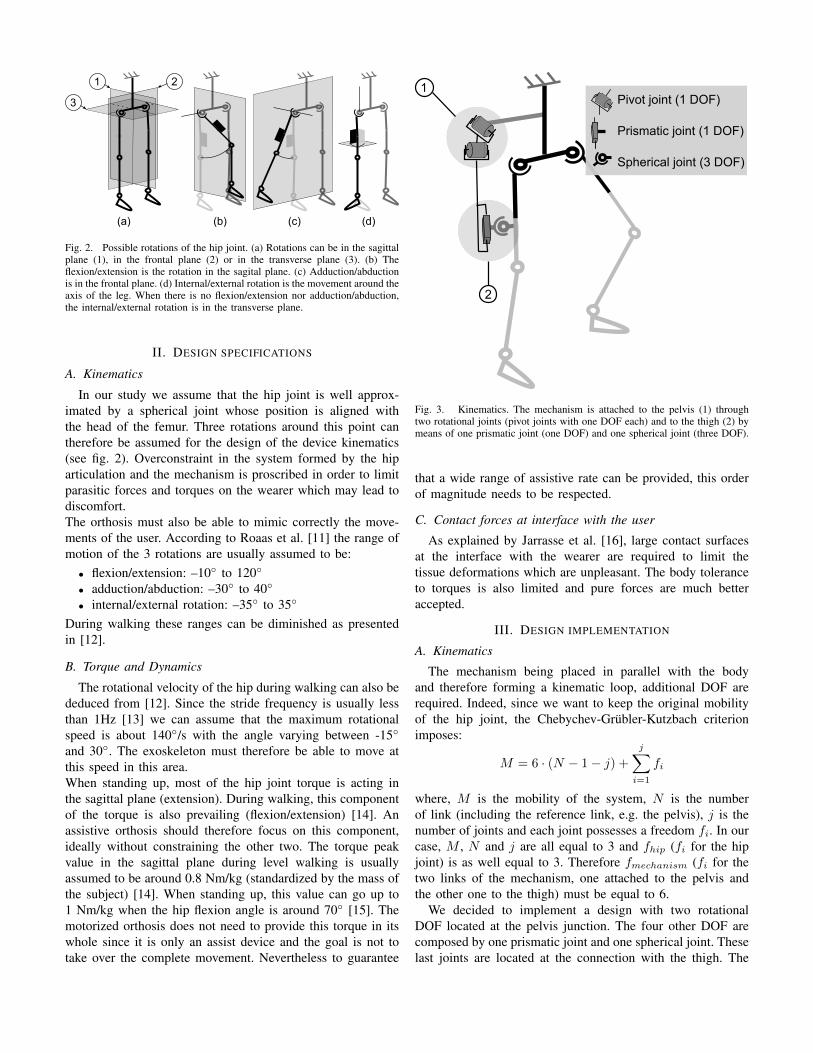
Fig. 2. Possible rotations of the hip joint. (a) Rotations can be in the sagittalplane (1), in the frontal plane (2) or in the transverse plane (3). (b) Theflexion/extension is the rotation in the sagital plane. (c) Adduction/abductionis in the frontal plane. (d) Internal/external rotation is the movement around theaxis of the leg. When there is no flexion/extension nor adduction/abduction,the internal/external rotation is in the transverse plane.
II. DESIGN SPECIFICATIONS
A. Kinematics
In our study we assume that the hip joint is well approx-imated by a spherical joint whose position is aligned withthe head of the femur. Three rotations around this point cantherefore be assumed for the design of the device kinematics(see fig. 2). Overconstraint in the system formed by the hiparticulation and the mechanism is proscribed in order to limitparasitic forces and torques on the wearer which may lead todiscomfort.The orthosis must also be able to mimic correctly the move-ments of the user. According to Roaas et al. [11] the range ofmotion of the 3 rotations are usually assumed to be:
• flexion/extension: –10◦ to 120◦
• adduction/abduction: –30◦ to 40◦
• internal/external rotation: –35◦ to 35◦
During walking these ranges can be diminished as presentedin [12].
B. Torque and Dynamics
The rotational velocity of the hip during walking can also bededuced from [12]. Since the stride frequency is usually lessthan 1Hz [13] we can assume that the maximum rotationalspeed is about 140◦/s with the angle varying between -15◦
and 30◦. The exoskeleton must therefore be able to move atthis speed in this area.When standing up, most of the hip joint torque is acting inthe sagittal plane (extension). During walking, this componentof the torque is also prevailing (flexion/extension) [14]. Anassistive orthosis should therefore focus on this component,ideally without constraining the other two. The torque peakvalue in the sagittal plane during level walking is usuallyassumed to be around 0.8 Nm/kg (standardized by the mass ofthe subject) [14]. When standing up, this value can go up to1 Nm/kg when the hip flexion angle is around 70◦ [15]. Themotorized orthosis does not need to provide this torque in itswhole since it is only an assist device and the goal is not totake over the complete movement. Nevertheless to guarantee
Pivot joint (1 DOF)
Prismatic joint (1 DOF)
Spherical joint (3 DOF)
1
2
Fig. 3. Kinematics. The mechanism is attached to the pelvis (1) throughtwo rotational joints (pivot joints with one DOF each) and to the thigh (2) bymeans of one prismatic joint (one DOF) and one spherical joint (three DOF).
that a wide range of assistive rate can be provided, this orderof magnitude needs to be respected.
C. Contact forces at interface with the user
As explained by Jarrasse et al. [16], large contact surfacesat the interface with the wearer are required to limit thetissue deformations which are unpleasant. The body toleranceto torques is also limited and pure forces are much betteraccepted.
III. DESIGN IMPLEMENTATION
A. Kinematics
The mechanism being placed in parallel with the bodyand therefore forming a kinematic loop, additional DOF arerequired. Indeed, since we want to keep the original mobilityof the hip joint, the Chebychev-Grubler-Kutzbach criterionimposes:
M = 6 · (N − 1− j) +
j∑i=1
fi
where, M is the mobility of the system, N is the numberof link (including the reference link, e.g. the pelvis), j is thenumber of joints and each joint possesses a freedom fi. In ourcase, M , N and j are all equal to 3 and fhip (fi for the hipjoint) is as well equal to 3. Therefore fmechanism (fi for thetwo links of the mechanism, one attached to the pelvis andthe other one to the thigh) must be equal to 6.
We decided to implement a design with two rotationalDOF located at the pelvis junction. The four other DOF arecomposed by one prismatic joint and one spherical joint. Theselast joints are located at the connection with the thigh. The

kinematics is presented in fig. 3. With this kinematics, theflexion/extension movement of the leg is directly linked withthe angle of the second rotational joint in the kinematic chainof the mechanism. The internal rotation is made possible bythe fact that two spherical joints are placed next to each otherin the kinematic chain (one from the mechanism and one fromthe hip). The last rotation (i.e. the abduction/adduction) ismore challenging to handle. Due to the chosen kinematics,the adduction/abduction is allowed only if the flexion angle issmall. Indeed when the second rotational joint lifts (i.e. whenthe flexion angle increases), the axis of rotation of the leg ro-tates in the sagittal plane and the three axes are not orthogonalanymore. When the flexion angle is close to 90◦, the thigh isaligned with the axis of the first pivot joint thus causing asingularity (see fig. 4 (a)). The first consequence is that oneDOF of the leg gets locked (adduction/abduction). Notice thatthis effect does not appear on normal walking range but ratherin sitting positions (flexion angle typically >45◦). The secondconsequence is that the mechanism gains one DOF relativelyto the wearer’s body. This parasitic movement is not desiredand therefore we designed a cam system (see fig. 4 (c)) toprogressively lock it when the flexion angle gets greater than30◦. The actual range of motion of the first pivot joint as afunction of the second joint is presented in fig. 4 (b). The shapeof the cam is fairly complexe since the rotation that needs tobe constrained depends on the second rotational joint. Themovement of the cam follower therefore describes a curve in3D. Fig. 4 (d) shows the movement of the cam follower duringflexion with maximum permitted abduction.
B. Amplification mechanism
In order to assist efficiently both sit-to-stand and walking,a mechanism with a varying transmission ratio was designed(see fig. 5).
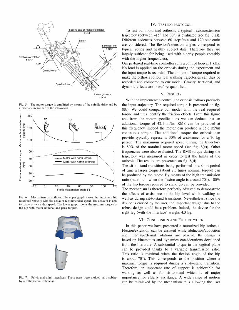
The maximal torque will be required during sit-to-standwhen the flexion angle is between 70◦and 80◦ [15]. The goalis to have a torque as large as possible in this area with amotion range and a velocity being able to fit with humangait. We developed a back drivable mechanism actuated by a60W motor and a spindle drive from Maxon. The peak forceprovided by this actuator is 1 kN and its maximum speed isabout 250 mm/s on a travel of 200 mm. In order to havea sufficient workspace with enough velocity and torque, amechanism inspired by excavators was studied. The maximumvelocities and the possible torques as function of the positionare presented on fig. 6. It can be observed that the maximumtorque is higher in the area that will be used during sit-to-stand movements. On the other hand a higher velocity can bereached in the walking range of motion.
C. Interface with the user
The interface with the user is ensured by an orthosisdesigned by a professional orthopaedic technician (see Fig. 7).The interface was molded on a subject in order to perfectly fitwith the different body parts. Despite this customized design,the orthosis was tested on several subjects and showed an
(a)
(b)
(c)
−20 0 20 40 60 80 100 120
−10
0
10
20
30
Firs
t piv
ot r
otat
ion
rang
e [°
]
Flexion/extension angle [°]
(d)
Fig. 4. Management of the adduction/abduction angle. (a) When the flexionangle increases, the leg tends to align itself with the first pivot joint. When theflexion angle is around 90◦, there is a singularity. (b) To avoid the singularity,the angle of the first joint was constrained as shown in the graph. (c) To doso, we designed a cam system to prevent the rotation of the mechanism whenthe flexion angle increases. (d) The movement of the cam follower on thecam is shown at different flexion angles.
excellent comfort (yound and healthy males between 1.7 m to2 m high). The contact with the user applies on large surfacesas required by our specifications. The proposed kinematicsimposes only forces at the thigh connection which limitsthe discomfort. Indeed the last link is a ball joint whichcannot transmit torques. Meanwhile the pelvis can be subjectto torques. However the interface being very large, no skindeformation can be observed. Thanks to this interface, donningand doffing are relatively easy for an experimental device.Nevertheless, improvements would still be needed for enablingan elderly user to be autonomous with the orthosis.
Motor
Linear guidway
Spherical joint
Cam
Cam follower
Spindle drive
Second axis of rotation (actuated)
First axis of rotation1 DOF
1 DOF
1 DOF
3 DOF
Fig. 5. The motor torque is amplified by means of the spindle drive and bya mechanism similar to the excavators.
Max
imum
flex
ion/
exte
nsio
n ve
loci
ty [°
/s]
100
180
260
Fle
xion
/ext
ensi
on to
rque
[Nm
]
Flexion/extension angle [°]
Motor with peak torqueMotor with nominal torque
20
40
60
80
100
Fig. 6. Mechanism capabilities. The upper graph shows the maximum hiprotational velocity with the actuator recommended speed. The actuator is ableto rotate at twice this speed. The lower graph shows the maxium torques atthe hip with motor nominal and peak torques.
Fig. 7. Pelvis and thigh interfaces. These parts were molded on a subjectby a orthopaedic technician.
IV. TESTING PROTOCOL
To test our motorized orthosis, a typical flexion/extensiontrajectory (between –15◦ and 30◦) is evaluated (see fig. 8(a)).Different cadences between 60 steps/min and 120 steps/minare considered. The flexion/extension angles correspond totypical young and healthy subject data. Therefore they arelargely sufficent for being used with elderly people (notablywith the higher frequencies).Our pc-based real-time controller runs a control loop at 1 kHz.No load is applied on the orthosis during the experiment andthe input torque is recorded. The amount of torque required tomake the orthosis follow real walking trajectories can thus berecorded and compared to our model. Gravity, frictional, anddynamic effects are therefore quantified.
V. RESULTS
With the implemented control, the orthosis follows preciselythe input trajectory. The required torque is presented on fig.8(b). We could compare our model with the real requiredtorque and thus identify the friction effects. From this figureand from the motor specifications we can deduce that anadditional torque of 42.1 mNm RMS can be provided atthis frequency. Indeed the motor can produce a 85.6 mNmcontinuous torque. The additional torque the orthosis canprovide typically represents 30% of assistance for a 70 kgperson. The maximum required speed during the trajectoryis 80% of the nominal motor speed (see fig. 8(c)). Otherfrequencies were also evaluated. The RMS torque during thetrajectory was measured in order to test the limits of theorthosis. The results are presented on fig. 8(d).The sit-to-stand transitions being performed in a short periodof time a larger torque (about 2.5 times nominal torque) canbe produced by the motor. By means of the high transmissionratio (maximum when the flexion angle is around 70◦), 100%of the hip torque required to stand up can be provided.The mechanism is therefore perfectly adjusted to demonstratethe effects of assistance at the hip level while walking aswell as during sit-to-stand transitions. Nevertheless, since thedevice is carried by the user, the important weight due to therobust design could be a problem. Indeed, the device for theright leg (with the interface) weighs 4.3 kg.
VI. CONCLUSION AND FUTURE WORK
In this paper we have presented a motorized hip orthosis.Flexion/extention can be assisted while abduction/adductionand internal/external rotations are passive. Its design isbased on kinematics and dynamics considerations developedfrom the literature. A substantial torque in the sagittal planecan be provided thanks to a variable transmission ratio.This ratio is maximal when the flexion angle of the hipis about 70◦). This corresponds to the position where amaximal torque is required during a sit-to-stand transition.Therefore, an important rate of support is achievable forwalking as well as for sit-to-stand which is of majorimportance for elderly assistance. A wide range of motioncan be mimicked by the mechanism thus allowing the user

−20
−10
0
10
20
30
40
Fle
xion
/Ext
ensi
on a
ngle
[°]
(a)
0 0.2 0.4 0.6 0.8 1Time [s]
1.2
Flexion/Extension angle [°]
Mot
or s
peed
[rpm
]
−4000
0
4000
8000
−8000-15 0 15 30
100
Mot
or to
rque
[mN
m]
(b)
0 0.2 0.4 0.6 0.8 1Time [s]
1.2
0
−100
(c)
Measured torqueModel torque with frictionModel torque without friction
0
20
40
60
80
0.5 0.6 0.7 0.8 0.9 1
Stride frequency [Hz]
Mot
or R
MS
torq
ue [m
Nm
]
(d)
Fig. 8. (a) Typical walk trajectory we used for testing the mechanismcapabilities. In this case the frequency is 0.83 Hz, which correspond to 100steps/min. (b) The corresponding torque during the trajectoy was recordedand compared to our model. The torque RMS value is 43.5 mNm whichcorresponds to 50% of the nominal motor torque. (c) The motor speed duringthe trajectory is maximum 80% of its nominal value. (d) RMS value of themotor torque during the trajectory at different frequencies. The maximumfrequency is around 1 Hz. In that case no assistance can be provided.
to move naturally during walking. The combination offlexion (more than 60◦) with adduction/abduction is howeverconstrained by a cam mechanism for practical reasons. Firsttests have shown that gravity, friction and dynamic effectsare well compensated. First impressions while wearing theorthosis in a transparent mode (i.e. by compensating thegravity, friction and dynamical effects) are very encouragingdespite the important weight of the device. Future workwill focus on strategies to assist walking, stair climbing
and sit-to-stand transitions. Tests on elderly subjects willbe conducted in order to validate the usefulness of this device.
ACKNOWLEDGEMENT
This research was supported by the National Center ofCompetence in Research Robotics. We also would like tothank “Amrein Orthopedie” for their help during the designof the interface.
REFERENCES
[1] D. H. Paterson, D. Govindasamy, M. Vidmar, D. A. Cunningham, andJ. J. Koval, “Longitudinal study of determinants of dependence in anelderly population,” Journal of the American Geriatrics Society, vol. 52,pp. 1632–1638, February 2004.
[2] J. Cohen, “Human population: The next half century,” Science, vol.302, no. 5648, pp. 1172–1175, December 2003. [Online]. Available:http://www.sciencemag.org/cgi/doi/10.1126/science.1088665
[3] H. Herr, “Exoskeletons and orthoses: classification, design challengesand future directions,” Journal of NeuroEngineering and Rehabilitation,vol. 6, February 2009.
[4] Y. Stauffer, Y. Allemand, M. Bouri, J. Fournier, R. Clavel, P. Metrailler,R. Brodard, and F. Reynard, “The walktrainer—a new generation ofwalking reeducation device combining orthoses and muscle stimulation,”Neural Systems and Rehabilitation Engineering, IEEE Transactions on,vol. 17, pp. 38–45, February 2009.
[5] S. Jezernik, G. Colombo, T. Keller, H. Frueh, and M. Morari, “Roboticorthosis lokomat: a rehabilitation and research tool,” Neuromodulation:Technology at the Neural Interface, vol. 6, pp. 108–115, February 2003.
[6] H. Kawamoto and Y. Sankai, “Power assist system hal-3 for gait disorderperson,” Computers helping people with special needs, pp. 19–29,February 2002.
[7] K. Kong and D. Jeon, “Design and control of an exoskeleton forthe elderly and patients,” Mechatronics, IEEE/ASME Transactions on,vol. 11, pp. 428–432, February 2006.
[8] H. Shimada, T. Hirata, Y. Kimura, T. Naka, K. Kikuchi, K. Oda, K. Ishii,K. Ishiwata, and T. Suzuki, “Effects of a robotic walking exercise onwalking performance in communitydwelling elderly adults,” Geriatrics& gerontology international, vol. 9, pp. 372–381, February 2009.
[9] P. DeVita and T. Hortobagyi, “Age causes a redistribution of joint torquesand powers during gait,” Journal of Applied Physiology, vol. 88, pp.1804–1811, February 2000.
[10] J. O. JudgeRoy, B. D. III, S. unpuu, B. Davis, J. O. JudgeRoy,and S. Ounpuu, “Step length reductions in advanced age: Therole of ankle and hip kinetics,” The Journals of GerontologySeries A: Biological Sciences and Medical Sciences, vol. 51A,no. 6, pp. M303–M312, December 1996. [Online]. Available:http://biomedgerontology.oxfordjournals.org/content/51A/6/M303.short
[11] A. Roaas and G. B. Andersson, “Normal range of motion of the hip,knee and ankle joints in male subjects, 30-40 years of age,” ActaOrthopaedica, vol. 53, pp. 205–208, February 1982.
[12] F. C. Anderson and M. G. Pandy, “Dynamic optimization of humanwalking,” Journal of biomechanical engineering, vol. 123, p. 381,February 2001.
[13] D. Winter, “Kinematic and kinetic patterns in human gait:Variability and compensating effects,” Human Movement Science,vol. 3, no. 1-2, pp. 51–76, April 1984. [Online]. Available:http://linkinghub.elsevier.com/retrieve/pii/0167945784900058
[14] A. Cappozzo, “Gait analysis methodology,” Human Movement Science,vol. 3, no. 1-2, pp. 27–50, April 1984. [Online]. Available:http://www.sciencedirect.com/science/article/pii/0167945784900046
[15] M. K. Mak, O. Levin, J. Mizrahi, and C. W. Hui-Chan, “Joint torquesduring sit-to-stand in healthy subjects and people with parkinson’sdisease,” Clinical biomechanics (Bristol, Avon), vol. 18, pp. 197–206,February 2003.
[16] N. Jarrasse and G. Morel, “A methodology to design kinematicsof fixations between an orthosis and a human member,” IntelligentMechatronics, pp. 1958–1963, February 2009. [Online]. Available:http://ieeexplore.ieee.org/xpls/absall.jsp?arnumber = 5229776