Atomizer: A Dynamic Atomicity Checker For Multithreaded Programs
Upload
trinhxuyenCategory
view
215download
0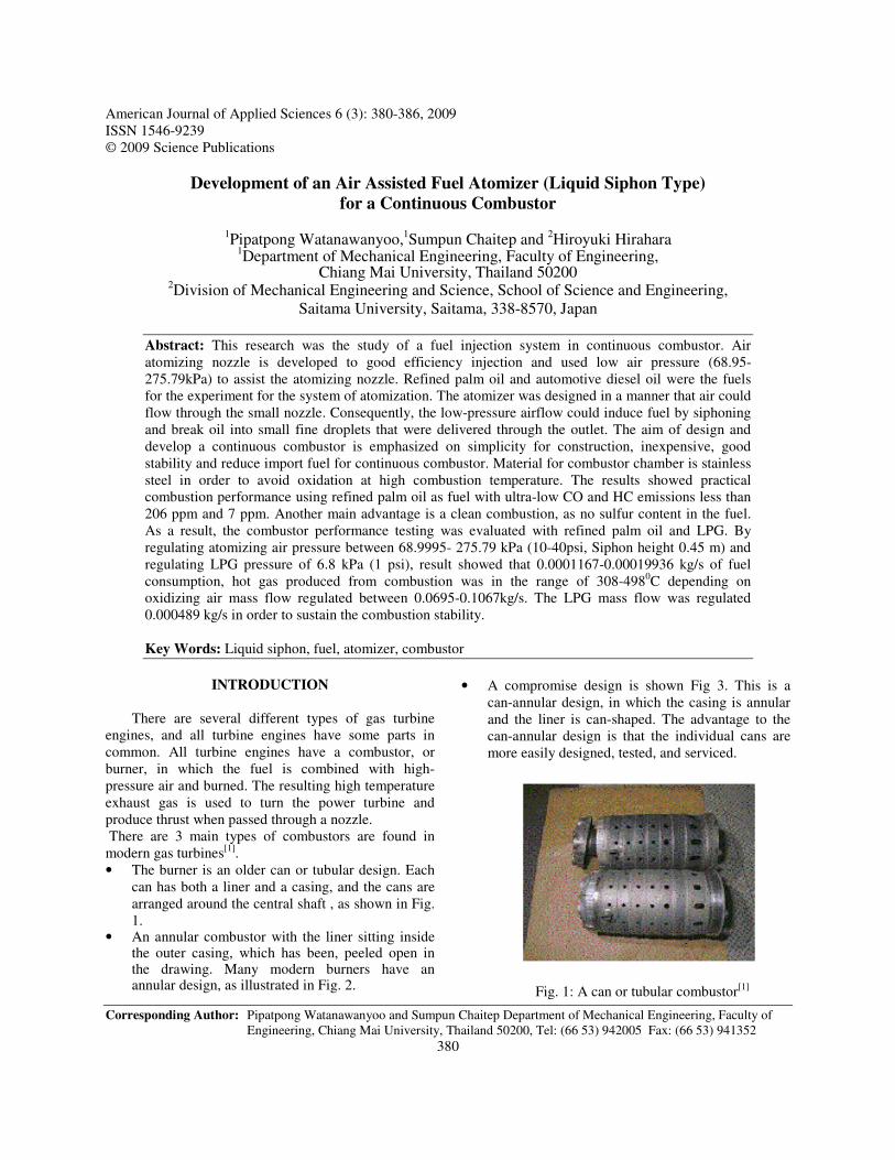
American Journal of Applied Sciences 6 (3): 380-386, 2009 ISSN 1546-9239 © 2009 Science Publications
Corresponding Author: Pipatpong Watanawanyoo and Sumpun Chaitep Department of Mechanical Engineering, Faculty of Engineering, Chiang Mai University, Thailand 50200, Tel: (66 53) 942005 Fax: (66 53) 941352
380
Development of an Air Assisted Fuel Atomizer (Liquid Siphon Type)
for a Continuous Combustor
1Pipatpong Watanawanyoo,1Sumpun Chaitep and 2Hiroyuki Hirahara 1Department of Mechanical Engineering, Faculty of Engineering,
Chiang Mai University, Thailand 50200 2Division of Mechanical Engineering and Science, School of Science and Engineering,
Saitama University, Saitama, 338-8570, Japan
Abstract: This research was the study of a fuel injection system in continuous combustor. Air atomizing nozzle is developed to good efficiency injection and used low air pressure (68.95-275.79kPa) to assist the atomizing nozzle. Refined palm oil and automotive diesel oil were the fuels for the experiment for the system of atomization. The atomizer was designed in a manner that air could flow through the small nozzle. Consequently, the low-pressure airflow could induce fuel by siphoning and break oil into small fine droplets that were delivered through the outlet. The aim of design and develop a continuous combustor is emphasized on simplicity for construction, inexpensive, good stability and reduce import fuel for continuous combustor. Material for combustor chamber is stainless steel in order to avoid oxidation at high combustion temperature. The results showed practical combustion performance using refined palm oil as fuel with ultra-low CO and HC emissions less than 206 ppm and 7 ppm. Another main advantage is a clean combustion, as no sulfur content in the fuel. As a result, the combustor performance testing was evaluated with refined palm oil and LPG. By regulating atomizing air pressure between 68.9995- 275.79 kPa (10-40psi, Siphon height 0.45 m) and regulating LPG pressure of 6.8 kPa (1 psi), result showed that 0.0001167-0.00019936 kg/s of fuel consumption, hot gas produced from combustion was in the range of 308-4980C depending on oxidizing air mass flow regulated between 0.0695-0.1067kg/s. The LPG mass flow was regulated 0.000489 kg/s in order to sustain the combustion stability. Key Words: Liquid siphon, fuel, atomizer, combustor
INTRODUCTION
There are several different types of gas turbine engines, and all turbine engines have some parts in common. All turbine engines have a combustor, or burner, in which the fuel is combined with high-pressure air and burned. The resulting high temperature exhaust gas is used to turn the power turbine and produce thrust when passed through a nozzle. There are 3 main types of combustors are found in modern gas turbines[1]. • The burner is an older can or tubular design. Each
can has both a liner and a casing, and the cans are arranged around the central shaft , as shown in Fig. 1.
• An annular combustor with the liner sitting inside the outer casing, which has been, peeled open in the drawing. Many modern burners have an annular design, as illustrated in Fig. 2.
• A compromise design is shown Fig 3. This is a can-annular design, in which the casing is annular and the liner is can-shaped. The advantage to the can-annular design is that the individual cans are more easily designed, tested, and serviced.
Fig. 1: A can or tubular combustor[1]
Am. J. Applied Sci., 6 (3): 380-386, 2009
381
Fig. 2: An annular combustor[1]
Fig. 3: A can - annular combustor[1]
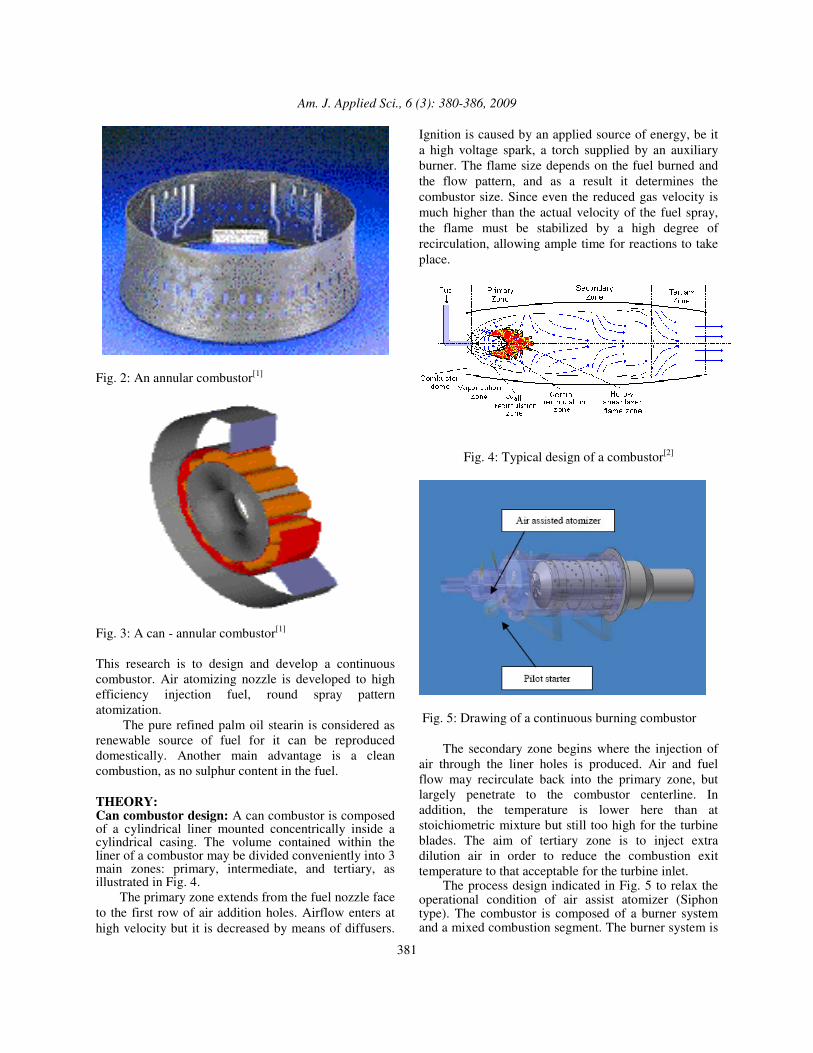
This research is to design and develop a continuous combustor. Air atomizing nozzle is developed to high efficiency injection fuel, round spray pattern atomization. The pure refined palm oil stearin is considered as renewable source of fuel for it can be reproduced domestically. Another main advantage is a clean combustion, as no sulphur content in the fuel. THEORY: Can combustor design: A can combustor is composed of a cylindrical liner mounted concentrically inside a cylindrical casing. The volume contained within the liner of a combustor may be divided conveniently into 3 main zones: primary, intermediate, and tertiary, as illustrated in Fig. 4. The primary zone extends from the fuel nozzle face to the first row of air addition holes. Airflow enters at high velocity but it is decreased by means of diffusers.
Ignition is caused by an applied source of energy, be it a high voltage spark, a torch supplied by an auxiliary burner. The flame size depends on the fuel burned and the flow pattern, and as a result it determines the combustor size. Since even the reduced gas velocity is much higher than the actual velocity of the fuel spray, the flame must be stabilized by a high degree of recirculation, allowing ample time for reactions to take place.
Fig. 4: Typical design of a combustor[2]
Fig. 5: Drawing of a continuous burning combustor The secondary zone begins where the injection of air through the liner holes is produced. Air and fuel flow may recirculate back into the primary zone, but largely penetrate to the combustor centerline. In addition, the temperature is lower here than at stoichiometric mixture but still too high for the turbine blades. The aim of tertiary zone is to inject extra dilution air in order to reduce the combustion exit temperature to that acceptable for the turbine inlet. The process design indicated in Fig. 5 to relax the operational condition of air assist atomizer (Siphon type). The combustor is composed of a burner system and a mixed combustion segment. The burner system is
Am. J. Applied Sci., 6 (3): 380-386, 2009
382
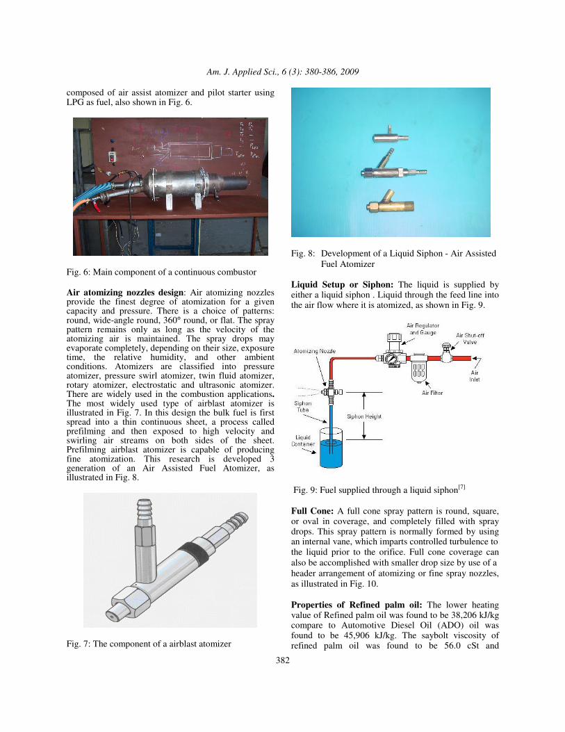
composed of air assist atomizer and pilot starter using LPG as fuel, also shown in Fig. 6.
Fig. 6: Main component of a continuous combustor Air atomizing nozzles design: Air atomizing nozzles provide the finest degree of atomization for a given capacity and pressure. There is a choice of patterns: round, wide-angle round, 360° round, or flat. The spray pattern remains only as long as the velocity of the atomizing air is maintained. The spray drops may evaporate completely, depending on their size, exposure time, the relative humidity, and other ambient conditions. Atomizers are classified into pressure atomizer, pressure swirl atomizer, twin fluid atomizer, rotary atomizer, electrostatic and ultrasonic atomizer. There are widely used in the combustion applications. The most widely used type of airblast atomizer is illustrated in Fig. 7. In this design the bulk fuel is first spread into a thin continuous sheet, a process called prefilming and then exposed to high velocity and swirling air streams on both sides of the sheet. Prefilming airblast atomizer is capable of producing fine atomization. This research is developed 3 generation of an Air Assisted Fuel Atomizer, as illustrated in Fig. 8.
Fig. 7: The component of a airblast atomizer
Fig. 8: Development of a Liquid Siphon - Air Assisted
Fuel Atomizer Liquid Setup or Siphon: The liquid is supplied by either a liquid siphon . Liquid through the feed line into the air flow where it is atomized, as shown in Fig. 9.
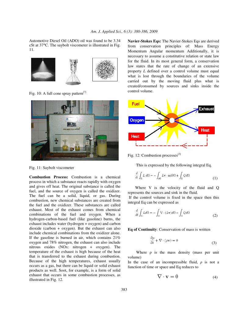
Fig. 9: Fuel supplied through a liquid siphon[7] Full Cone: A full cone spray pattern is round, square, or oval in coverage, and completely filled with spray drops. This spray pattern is normally formed by using an internal vane, which imparts controlled turbulence to the liquid prior to the orifice. Full cone coverage can also be accomplished with smaller drop size by use of a header arrangement of atomizing or fine spray nozzles, as illustrated in Fig. 10. Properties of Refined palm oil: The lower heating value of Refined palm oil was found to be 38,206 kJ/kg compare to Automotive Diesel Oil (ADO) oil was found to be 45,906 kJ/kg. The saybolt viscosity of refined palm oil was found to be 56.0 cSt and
Am. J. Applied Sci., 6 (3): 380-386, 2009
383
Automotive Diesel Oil (ADO) oil was found to be 3.34 cSt at 37°C. The saybolt viscometer is illustrated in Fig. 11.
Fig. 10: A full cone spray pattern[7]
Fig. 11: Saybolt viscometer Combustion Process: Combustion is a chemical process in which a substance reacts rapidly with oxygen and gives off heat. The original substance is called the fuel, and the source of oxygen is called the oxidizer. The fuel can be a solid, liquid, or gas. During combustion, new chemical substances are created from the fuel and the oxidizer. These substances are called exhaust. Most of the exhaust comes from chemical combinations of the fuel and oxygen. When a hydrogen-carbon-based fuel (like gasoline) burns, the exhaust includes water (hydrogen + oxygen) and carbon dioxide (carbon + oxygen). But the exhaust can also include chemical combinations from the oxidizer alone. If the gasoline is burned in air, which contains 21% oxygen and 78% nitrogen, the exhaust can also include nitrous oxides (NOx: nitrogen + oxygen). The temperature of the exhaust is high because of the heat that is transferred to the exhaust during combustion. Because of the high temperatures, exhaust usually occurs as a gas, but there can be liquid or solid exhaust products as well. Soot, for example, is a form of solid exhaust that occurs in some combustion processes, as illustrated in Fig. 12.
Navier-Stokes Eqs: The Navier-Stokes Eqs are derived from conservation principles of: Mass Energy Momentum Angular momentum Additionally, it is necessary to assume a constitutive relation or state law for the fluid. In its most general form, a conservation law states that the rate of change of an extensive property L defined over a control volume must equal what is lost through the boundaries of the volume carried out by the moving fluid plus what is created/consumed by sources and sinks inside the control volume.
Fig. 12: Combustion processes[3] This is expressed by the following integral Eq.
(1) Where V is the velocity of the fluid and Q represents the sources and sink in the fluid. If the control volume is fixed in the space then this integral Eq can be expressed as
(2) Eq of Continuity: Conservation of mass is written
(3) Where � is the mass density (mass per unit volume) In the case of an incompressible fluid, � is not a function of time or space and Eq reduces to (4)
Am. J. Applied Sci., 6 (3): 380-386, 2009
384
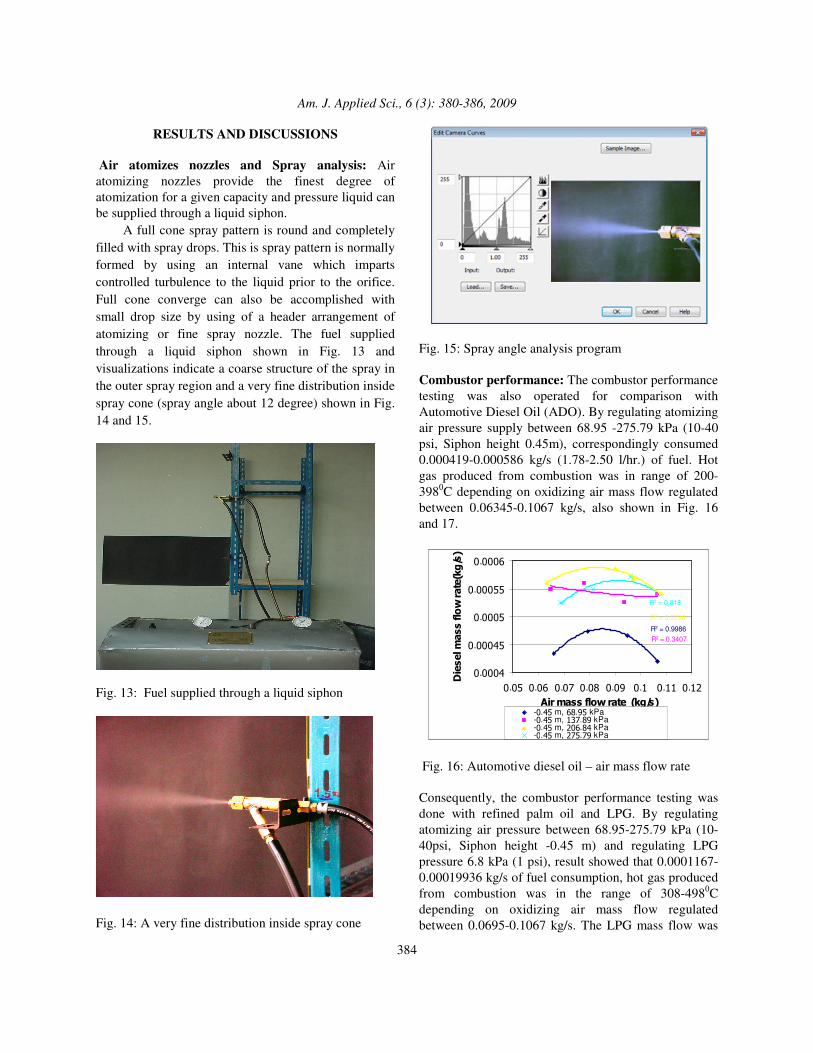
RESULTS AND DISCUSSIONS Air atomizes nozzles and Spray analysis: Air atomizing nozzles provide the finest degree of atomization for a given capacity and pressure liquid can be supplied through a liquid siphon. A full cone spray pattern is round and completely filled with spray drops. This is spray pattern is normally formed by using an internal vane which imparts controlled turbulence to the liquid prior to the orifice. Full cone converge can also be accomplished with small drop size by using of a header arrangement of atomizing or fine spray nozzle. The fuel supplied through a liquid siphon shown in Fig. 13 and visualizations indicate a coarse structure of the spray in the outer spray region and a very fine distribution inside spray cone (spray angle about 12 degree) shown in Fig. 14 and 15.
Fig. 13: Fuel supplied through a liquid siphon
Fig. 14: A very fine distribution inside spray cone
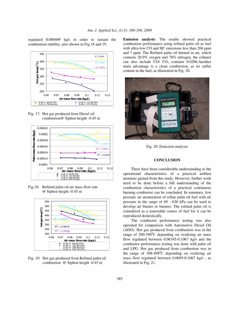
Fig. 15: Spray angle analysis program Combustor performance: The combustor performance testing was also operated for comparison with Automotive Diesel Oil (ADO). By regulating atomizing air pressure supply between 68.95 -275.79 kPa (10-40 psi, Siphon height 0.45m), correspondingly consumed 0.000419-0.000586 kg/s (1.78-2.50 l/hr.) of fuel. Hot gas produced from combustion was in range of 200-3980C depending on oxidizing air mass flow regulated between 0.06345-0.1067 kg/s, also shown in Fig. 16 and 17.
R2 = 0.9986
R2 = 0.818
R2 = 0.3407
R2 = 0.9738
�.����
�.�����
�.����
�.�����
�.����
�.���.���.���.�� �.�� �.� �.�� �.���������������� ��������
�� � ������������ ������
-�.��m, ��.��kPa-�.��m, ���.��kPa-�.��m, ��.��kPa-�.��m, ��.��kPa� ������������.��m, ��.��kPa)
Fig. 16: Automotive diesel oil – air mass flow rate Consequently, the combustor performance testing was done with refined palm oil and LPG. By regulating atomizing air pressure between 68.95-275.79 kPa (10-40psi, Siphon height -0.45 m) and regulating LPG pressure 6.8 kPa (1 psi), result showed that 0.0001167-0.00019936 kg/s of fuel consumption, hot gas produced from combustion was in the range of 308-4980C depending on oxidizing air mass flow regulated between 0.0695-0.1067 kg/s. The LPG mass flow was
Am. J. Applied Sci., 6 (3): 380-386, 2009
385
regulated 0.000489 kg/s in order to sustain the combustion stability, also shown in Fig.18 and 19.
R2 = 0.9985
R2 = 0.9697
R2 = 0.9824
R2 = 0.9404
��
��
���
���
���
���
�.�� �.�� �.�� �.�� �.� �.�� �.���������������� �������
�������� ����
o ��
-�.��m, ��.��kPa -�.��m, ���.��kPa-�.��m, ��.��kPa -�.��m, ��.��kPa� ������������.��m, ��.��kPa) � ������������.��m, ��.��kPa)
Fig. 17: Hot gas produced from Diesel oil
combustion@ Siphon height -0.45 m
R2 = 0.9942
R2 = 0.9981
R2 = 0.0861
R2 = 0.8546
�.����
�.����
�.�����
�.�����
�.�����
�.���
�.���
�.�� �.�� �.�� �.�� �.� �.�� �.���������������� �������
��������������� �������
-0.45 m, 68.95 kPa-0.45 m, 137.89 kPa-0.45 m, 206.84 kPa-0.45 m, 275.79 kPa� �����������0.45 m, 206.84 kPa)
Fig.18: Refined palm oil-air mass flow rate
@ Siphon height -0.45 m
R2 = 0.9999
R2 = 0.8818
R2 = 0.9702R2 = 0.8514
��
��
���
���
���
���
���
���
�.�� �.�� �.�� �.�� �.� �.�� �.���������������� �������
�������� ���o ��
-�.��m, ��.��kPa-�.��m, ���.��kPa-�.��m, ��.��kPa-�.��m, ��.��kPa� ������������.��m, ���.��kPa)
Fig. 19: Hot gas produced from Refined palm oil
combustion @ Siphon height -0.45 m
Emission analysis: The results showed practical combustion performance using refined palm oil as fuel with ultra-low CO and HC emissions less than 206 ppm and 7 ppm. The Refined palm oil burned in air, which contains 20.9% oxygen and 78% nitrogen, the exhaust can also include CO/ CO2 contains 0.0206.Another main advantage is a clean combustion, as no sulfur content in the fuel, as illustrated in Fig. 20.
Fig. 20: Emission analyser
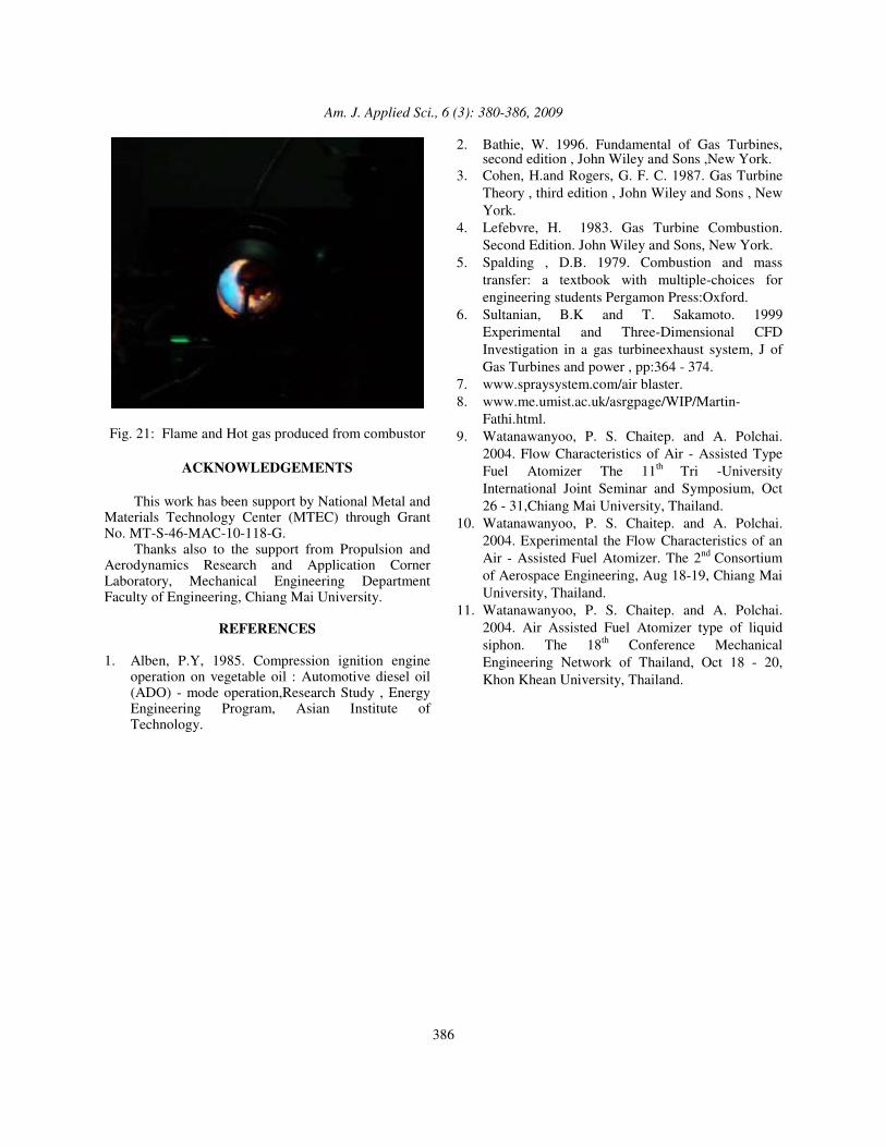
CONCLUSION There have been considerable understanding to the operational characteristics of a practical airblast atomizer gained from this study. However, further work need to be done before a full understanding of the combustion characteristics of a practical continuous burning combustor can be concluded. In summary, low pressure air atomization of refine palm oil fuel with air pressure in the range of 69 - 620 kPa can be used to develop air blaster or burners. The refined palm oil is considered as a renewable source of fuel for it can be reproduced domestically. The combustor performance testing was also operated for comparison with Automotive Diesel Oil (ADO). Hot gas produced from combustion was in the range of 200-3980C depending on oxidizing air mass flow regulated between 0.06345-0.1067 kg/s and the combustor performance testing was done with palm oil and LPG. Hot gas produced from combustion was in the range of 308-4980C depending on oxidizing air mass flow regulated between 0.0695-0.1067 kg/s , as illustrated in Fig. 21.
Am. J. Applied Sci., 6 (3): 380-386, 2009
386
Fig. 21: Flame and Hot gas produced from combustor
ACKNOWLEDGEMENTS This work has been support by National Metal and Materials Technology Center (MTEC) through Grant No. MT-S-46-MAC-10-118-G. Thanks also to the support from Propulsion and Aerodynamics Research and Application Corner Laboratory, Mechanical Engineering Department Faculty of Engineering, Chiang Mai University.
REFERENCES
1. Alben, P.Y, 1985. Compression ignition engine
operation on vegetable oil : Automotive diesel oil (ADO) - mode operation,Research Study , Energy Engineering Program, Asian Institute of Technology.
2. Bathie, W. 1996. Fundamental of Gas Turbines, second edition , John Wiley and Sons ,New York.
3. Cohen, H.and Rogers, G. F. C. 1987. Gas Turbine Theory , third edition , John Wiley and Sons , New York.
4. Lefebvre, H. 1983. Gas Turbine Combustion. Second Edition. John Wiley and Sons, New York.
5. Spalding , D.B. 1979. Combustion and mass transfer: a textbook with multiple-choices for engineering students Pergamon Press:Oxford.
6. Sultanian, B.K and T. Sakamoto. 1999 Experimental and Three-Dimensional CFD Investigation in a gas turbineexhaust system, J of Gas Turbines and power , pp:364 - 374.
7. www.spraysystem.com/air blaster. 8. www.me.umist.ac.uk/asrgpage/WIP/Martin-
Fathi.html. 9. Watanawanyoo, P. S. Chaitep. and A. Polchai.
2004. Flow Characteristics of Air - Assisted Type Fuel Atomizer The 11th Tri -University International Joint Seminar and Symposium, Oct 26 - 31,Chiang Mai University, Thailand.
10. Watanawanyoo, P. S. Chaitep. and A. Polchai. 2004. Experimental the Flow Characteristics of an Air - Assisted Fuel Atomizer. The 2nd Consortium of Aerospace Engineering, Aug 18-19, Chiang Mai University, Thailand.
11. Watanawanyoo, P. S. Chaitep. and A. Polchai. 2004. Air Assisted Fuel Atomizer type of liquid siphon. The 18th Conference Mechanical Engineering Network of Thailand, Oct 18 - 20, Khon Khean University, Thailand.