Social Representations of CMCs in Mozambique: work in progress @ TASCHA

1
DEVELOPMENT OF ADVANCED ENVIRONMENTAL BARRIER COATINGS
FOR SIC/SIC COMPOSITES At NASA GRC: PRIME-RELIANT DESIGN AND
DURABILITY PERSPECTIVES
Dongming Zhu
Materials and Structures Division
NASA John H. Glenn Research Center
Cleveland, Ohio 44135
Advanced Ceramic Matrix Composites:
Science and Technology of Materials, Design, Applications, Performance and Integration
An ECI Conference, Santa Fe, NM
November 5-9, 2017
The work was supported by NASA Fundamental Aeronautics Program (FAP) Transformational Tools
and Technologies (TTT) Project
https://ntrs.nasa.gov/search.jsp?R=20180000408 2018-06-22T07:15:53+00:00Z

2
NASA’s Advanced Environmental Barrier Coating Systems for
Ceramic Matrix Composites (CMCs): Enabling Technology for Next Generation Low Emission, High Efficiency and
Light-Weight Propulsion, and Extreme Environment Material Systems
— NASA Environmental Barrier Coatings (EBCs) development objectives
• Help achieve future engine temperature and performance goals
• Ensure system durability – towards prime reliant coatings and material systems
• Establish database, design tools and coating lifing methodologies
• Improve technology readiness
Entry, Descending and Landing: Ultra High Ceramics
and Coatings (UHTCC)Hybrid Electric Propulsion Aircraft
Fixed Wing Subsonic and Supersonics Aircraft

3
NASA Environmental Barrier Coating Development Goals
* Recession: <5 mg/cm2 per 1000 hr (40-50 atm., Mach 1~2)
** Component strength and toughness requirements
• Emphasize temperature capability, performance and durability
• Develop 2700°F environmental barrier coating technologies
- For 2400°F (1316°C) and 2700°F (1482°C) Ceramic Matrix Composites (CMCs) in support of next generation turbine engines
- Focus on advanced CMC combustors and highly loaded turbine airfoils
- Particularly also emphasize highly loaded turbine blades
2400°F (1316°C) Gen I and Gen II SiC/SiC
CMCs
3000°F+ (1650°C+)
Gen I
Temperature
Capability (T/EBC) surface
Gen II – Current commercialGen III
Gen. IV
Increase in T
across T/EBC
Single Crystal Superalloy
Year
Ceramic Matrix Composite
Gen I
Temperature
Capability (T/EBC) surface
Gen II – Current commercialGen III
Gen. IV
Increase in T
across T/EBC
Single Crystal Superalloy
Year
Ceramic Matrix Composite
2700°F (1482C)
2000°F (1093°C)
Step increase in the material’s temperature capability
3000°F SiC/SiC CMC
airfoil and combustor
technologies
2700°F SiC/SiC thin
turbine EBC systems for
CMC airfoils
2800ºF
combustor
TBC
2500ºF
Turbine TBC 2700°F (1482°C) Gen III SiC/SiC CMCs

4
Outline
─ Environmental barrier coating systems: towards Prime-Reliant
systems• Thermomechanical, environment and thermochemical stability of EBCs
• Prime-reliant EBCs, initial design approach and requirements
─ Advanced environmental barrier coating systems (EBCs) for
CMC airfoils and combustors• NASA advanced turbine EBC coating system status
• Development and testing, durability perspectives
─ Design tool and life prediction perspectives of coated CMC
components• Advanced Testing
• Emphasizing thermomechanical, environment and thermochemical
interactions
─ Summary and future directions

5
Prime-Relaiant EBC Systems for Si-Based Ceramic Matrix
Composites
RE doped Hf, Hf RE silicate and/or multi-rare earth silicate EBCs
2700°F bond coats
Interlayer
SiC/SiC CMC
Low expansion alloyed-HfO2, and HfO2 aluminates
HfO2-Y2O3-Yb2O3-Gd2O3-(SiO2)
HfO2-Y2O3-Yb2O3-Gd2O3-Ta2O2-TiO2-(SiO2)e.g.,
− NASA’s advanced environmental barrier and bond coat development: Prime-reliant
designs
• High toughness and low conductivity EBC top coat
• Alternating Composition Layered Coatings (ACLCs) and composite coatings,
including improving impact resistance
• Advanced doped multicomponent EBCs
• Prime-reliant designed bond coats
• Ultimately environmental resistant CMCs with high thermal conductivities

6
Fundamental Recession Issues of CMCs and EBCs
- Recession of Si-based Ceramics
(a) Convective; (b) Convective with film-cooling
- Low SiO2 activity EBC systems
- Advanced rig testing and modeling
Complex recession behavior of CMC and EBCs studied in NASA High
Pressure Burner Rig, included film-cooled recession
SiO2 + 2H2O(g) = Si(OH)4(g)
Recession rate = const. V1/2 P(H2O)2/(Ptotal)
1/2
Combustion gas
SiO2 + 2H2O(g) = Si(OH)4(g)
Combustion gas
Cooling gas
(a) (b)

7
Fundamental Recession Issues of CMCs and EBCs -
Continued
Combustor coating Turbine coating
- Early generations of environmental barrier coatings - EBC systems, improved stability in turbine environments
HfO2 based low k - APS HfO2 based low k – EB-PVD
― EBC stability evaluated on SiC/SiC CMCs in high velocity, high pressure burner rig environment
Exposure Time (hrs)
0 20 40 60 80 100
SiC
Wt.
Lo
ss (
mg
/cm
2)
-15
-10
-5
0
1385 C
1446 C
1252 C
1343 C
Robinson and Smialek, J. Am. Ceram Soc. 1999
°
°
°
°

8
Fundamental Recession Issues of CMCs and EBCs -
Continued
Combustor coating Turbine coating
- Early generations of environmental barrier coatings - EBC systems
HfO2 based low k - APS HfO2 based low k – EB-PVD
― EBC stability evaluated on SiC/SiC CMCs in high velocity, high pressure burner rig environment
0.001
0.01
0.1
1
10
0.0005 0.00055 0.0006 0.00065 0.0007 0.00075 0.0008
Spec
ific
wei
gh
t ch
ang
e, m
g/c
m2-h
1/T, K-1
1300
Temperature, °C
14001500 12001600
SiC/SiC under high velocity
BSAS Baseline
1100 1000
Tyranohex SA (6 atm, 200m/s)
Tyranohex SA (16 atm, 30m/s)
NASA EBC stability devlopment goal: 5 mg/cm2-h
High pressure burner rig, 16 atm, 31 hr

9
Environmental Barrier Coating in Simulated Load-Fatigue Testing
Environments (Laser High Heat Flux Rig)
failure
failure
failure
failure
Fatigue strains (amplitudes) – Time Plot Thermal conductivity – Time Plot
In steam-jet, EBC cracking and
recession
- EBC Yb2SiO5/Yb2Si2O7/Si on Melt Infiltrated (MI) Prepreg SiC/SiC CMC substrates
- Tested in air, furnace isothermal at 1316°C; and in heat flux steam, at TEBC 1316°C, TCMC at
~1200°C
- Lower CMC failure strain observed in the steam-heat flux test environment
- Ytterbium mono-silicate recession observed in the test
- Thermal conductivity for monitoring coating delamination

10
Environmental Barrier Coating in Simulated Load-Fatigue
Testing Environments (Laser High Heat Flux Rig) - Continued
In steam; EBC cracking and volatility
In Air; EBC cracking
- Crack and recession failure in air and steam tests
Comp
onent
Type Conc.,
At%
Conc.,
Wt%,
O Calc 49.07 9.59
Si Calc 9.79 3.36
Yb Calc 41.14 87.04
Total 100.00 100.00
EDS 25D
25D

11
NASA advanced EBC systems emphasizing high stability HfO2- and ZrO2-RE2O3-SiO2 EBC
systems and HfO2-Si and Rare Earth – Silicon bond coat systems
― NASA multicomponent Rare Earth RE2Si2-xO7-2x , such as (Yb,Gd,Y) 2Si2-xO7-2x environmental
barrier systems
― Rare earth-doped HfO2-ZrO2, and HfO2-doped Rare Earth (RE) silicates are among the
advanced EBC systems
• Improved high temperature stability and creep strength;
• Facilitating nano-cluster formation with high concentration rare earth compound phases;
• Improving CMAS resistance
Advanced NASA EBC Developments
TEM-EELS
Composition map

12
NASA EBC Bond Coat Systems
12
NASA EBC Systems
• HfO2 -RE2O3-SiO2/RE2Si2-xO7-2x environmental barrier systems
• Controlled silica content and rare earth dopants to improve EBC stability, toughness,
erosion and CMAS resistance
• HfO2-Si based bond coat, controlled oxygen partial pressure
• Advanced rare earth-Si composition systems for 2700°F+ long-term applications
• Early RE2O3-SiO2-Al2O3 or YAG Systems
• Develop prime-reliant composite EBC-CMCs, HfSiRE(CN) systems
Bond coat systems for prime reliant EBCs; capable of self-healing
13
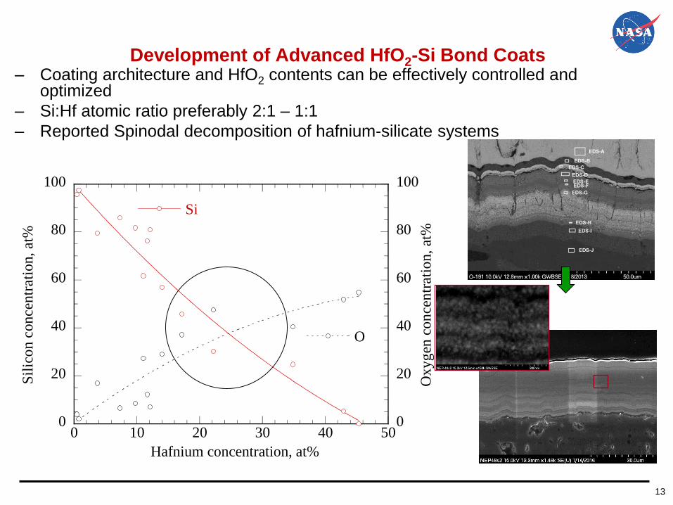
Development of Advanced HfO2-Si Bond Coats– Coating architecture and HfO2 contents can be effectively controlled and
optimized
– Si:Hf atomic ratio preferably 2:1 – 1:1
– Reported Spinodal decomposition of hafnium-silicate systems
0
20
40
60
80
100
0
20
40
60
80
100
0 10 20 30 40 50
Si
O
Sil
ico
n c
oncen
trati
on,
at%
Oxyg
en c
on
cen
trat
ion,
at%
Hafnium concentration, at%

14
Microstructures of Furnace Cyclic Tested GdYbSi(O) EBC
Systems— Cyclic tested cross-sections of PVD processed YbGdSi(O) bond coat
— Self-grown rare earth silicate EBCs and with some RE-containing SiO2 rich phase separations
— Relatively good coating adhesion and cyclic durability
1500°C, in air, 500, 1 h cycles
AB
B
A
Composition (mol%) spectrum Area #1
SiO2 67.98
Gd2O3 11.95
Yb2O3 20.07
Composition (mol%) spectrum Area #2
SiO2 66.03
Gd2O3 10.07
Yb2O3 23.9
- Complex coating architectures
after the testing
- Designed with EBC like
compositions – Self-grown
EBCs

15
Microstructures of Cyclic Tested GdYbSi(O) EBC
Systems- Continued
1500°C, in air, 500, 1 hr cycles
Outlined area SpotComposition (mol%)
SiO2 66.72
Gd2O3 8.62
Yb2O3 24.66
Composition (mol%)
SiO2 96.15
Gd2O3 1.2
Yb2O3 2.64
— Cyclic tested cross-sections of PVD processed YbGdSi(O) bond coat
— Self-grown rare earth silicate EBCs and with some RE-containing SiO2 rich phase separations
— Interface growth instability

16
Advanced EBC developments – Some Hybrid Air-Plasma
Spray/EB-PVD Turbine Combustor EBC Systems and Qualification
Tests• Achieved low thermal conductivity ranging from 1.0
- 1.7 W/m-K
• Demonstrated high pressure environmental
stability at 2600-2650°F, 12-20 atm. in the high
pressure burner rig
• Surface recession or micro-spallation for less
tougher coating systems
2” diameter ND3
EBC/SiC/SiC
specimen after
testing in the high
pressure burner rig
At 2600°F+, 200
m/s
High pressure burner rig tested new ND series Hybrid
EBC systems coated on 2” diameter Gen II Prepreg
SiC/SiC CMCs
ND2 ND6 ND7
Surface spallation

17
Erosion and Impact Aspects: Early Mach 0.3 Ballistic
Impact Tests of HfO2-Si Bond Coat EBC Systems
─ Advanced high toughness EBCs tested with comparable performance of best TBCs
─ More advanced EBC compositions currently also in developments
0.0
0.2
0.4
0.6
0.8
1.0
1.2
1.4
1.6
0.0 0.5 1.0 1.5 2.0 2.5
7YSZ and low k TBCs
ZrRETT
ATES series
ND2
ND3
ND6
ND7
SUP-ERA7.4 EBC
t'-ZrO2/NASA EBC
Cubic low k ZrO2 k-NASA EBC
Spal
led
are
a, c
m2
Energy, J
150 200 500250 350 400 450300
Projectile velocity, m/s
NASA SUP-ERA 7.4 EBC
ND6 NASA EBC
t'/ NASA EBCND7 NASA EBC
Spalled
ND2
ND3
ND6
SUP-ERA 7.4
ND3
ND6 EBC
ND7 EBC
SUP7.1A EBC
SUP-ERA 7.4 EBC
ND7

18
Advanced EBC Coating Material Strength Evaluations– High strength EBCs and bond coats are critical for prime-reliant designs
• Multicomponent EBCs and first-generation HfO2-Si bond coat achieved 150-200 MPa
strength at high temperature (1400°C+)
• Multicomponent silicates showed improved high temperature strengths compared to
baseline yttrium and ytterbium silicates
• High strength and high toughness are critical for erosion and fatigue cracking
resistance
0
50
100
150
200
250
300
350646-Specially toughened t' like HfO2648-EBC Bond Coat Constituent658-AE9932660-Y2Si2O7657-Zr-RE silicate669-Yb2Si2O7670-Rare Earth Disilicate681-HfO2-Si
0 200 400 600 800 1000 1200 1400 1600
Str
ength
, M
Pa
Temperature, °C
696-EBC Bond Coat Constituent
(Multi-component)
(Multi-component)
669-Yb2Si2O7
660-Y2Si2O7
659-Yb2SiO5
Flexure strengths of selected EBC materials

19
High Heat Flux and CMAS Resistance are Ensured by Advanced
High Melting Point Coating, and Multi-Component Compositions– Non stoichiometric characteristics of the CMAS – rare earth silicate reacted
apatite phases – up to 200 h testing
– Difference in partitioning of ytterbium vs. yttrium in apatite• Average AEO/RE2O3 ratio ~ 0.68 for ytterbium silicate – CMAS system
• Average AEO/RE2O3 ratio ~ 0.22 for yttrium silicate – CMAS system
Ahlborg and Zhu, Surface & Coatings Technology 237 (2013) 79–87.
RE2O3
SiO2
AEO
Composition in apatite (100 hr):
Yttrium Silicate EBC
Composition in apatite (100 hr):
Ytterbium Silicate EBC

20
High Heat Flux and CMAS Resistance Tests of Advanced EBC
Systems
– Multicomponent rare earth silicate EBC showed improved performance
– Silicate based coatings still sensitive to CMAS concentrations (estimated
variation between average CMAS at 25 mg/cm2 to more concentrated region
CMAS at 75 mg/cm2)
– Some coating damage occurred for EBCs in JETS tests at higher CMAS loading
regions
Laser rig test of advanced coating systems
4450 Cycles
Turbine vane EBC, CMAS JETS
tests (100 h)
Initially infiltrated
25h 50h 100h
0
500
1000
1500
2000
0 50 100 150
Tsurface, C
Tback, C
Tem
per
atu
re,
C
Time, hours
CMAS tempertaure

21
Thermal Gradient Tensile Creep Rupture Testing of Advanced
Turbine Environmental Barrier Coating SiC/SiC CMCs
─ Advanced high stability multi-component hafnia-rare earth silicate based turbine
environmental barrier coatings being successfully tested for 1000 hr creep rupture
─ EBC-CMC creep, fatigue and environmental interaction is being emphasized
Cooling
shower head
jets
Test specimen
High
temperature
extensometer
Laser beam
delivery optic
system
EBC coated tensile specimen
1
Tota
l st
rain
, %
0.0
0.5
1.0
1.5
0 200 400 600 800 1000 1200
Time, hours
Gen II CMC with advanced EBC
tested 20 ksi, 1316°C
Gen II CMC-uncoated
Tested at 20 ksi, 1316°C
Gen II CMC uncoated
Tested at 15 ksi, 1316°C
Typical premature
failure
Tsurface = 2700°F
Tinterface= 2500°F
TCMC back=2320°F
Gen II CMC with advanced EBC
Tested at 15 ksi & heat flux
Tsurface = 2750ºF
Tinterface = 2450ºF
TCMC back = 2250ºC
Gen II CMC with advanced EBC
Tested at 20 ksi & heat flux
2400 F
2400 F
2250 F2400 F
22
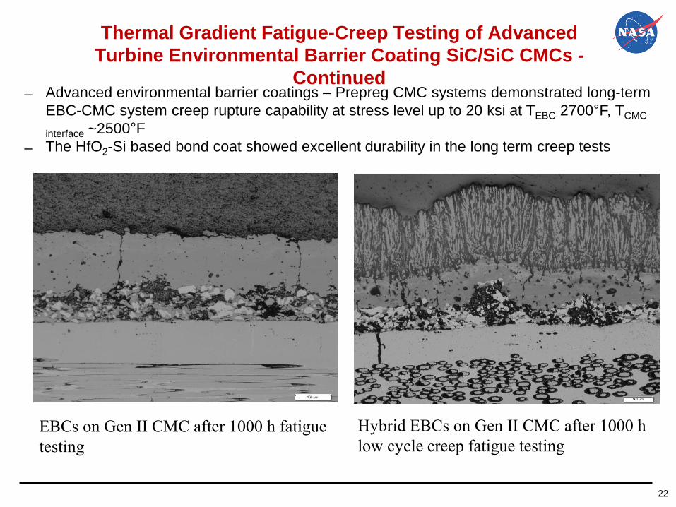
Advanced environmental barrier coatings – Prepreg CMC systems demonstrated long-term
EBC-CMC system creep rupture capability at stress level up to 20 ksi at TEBC 2700°F, TCMC
interface ~2500°F
The HfO2-Si based bond coat showed excellent durability in the long term creep tests
Thermal Gradient Fatigue-Creep Testing of Advanced
Turbine Environmental Barrier Coating SiC/SiC CMCs -
Continued
Hybrid EBCs on Gen II CMC after 1000 h
low cycle creep fatigue testing
EBCs on Gen II CMC after 1000 h fatigue
testing

2323
High Heat Flux Thermomechanical fatigue Tests of
Advanced NASA EBC-Bond Coats Systems on CMCs• Laser High Heat Flux themomechanical fatigue testing of a HfO2-Si and NASA advanced
EBC baseline with steam at 3 Hz, 2600-2700°F, and 69 MPa maximum stress with stress
ratio 0.05, completed 500 h testing
• Tsurface = 1500-1600°C
• T= 1320-1350°C
• Heat Flux = 170 W/cm2
• Specimen had some degradations 3 hz fatigue testing at 10 ksi loading
Completed 500 hr testing
Testing proving vital failure
mechanisms in a simulated
test environments
EBCs
EBCs
Higher Si content HfO2-Si

24
EBC-CMC Thermal Gradient Creep Rupture and
Delamination Modeling An equivalent stress model is established for EBC multicrack stress intensity modeling:
emphasize creep, thermal gradient and stress rupture interactions
Benchmark failure modes established in EBC systems, strong bond coat beneficial
Finite Element Analysis (FEA) Modeling
D. Zhu and L. Ghosn, “Creep, Fatigue and Fracture Behavior of Environmental Barrier Coating and SiC-SiC Ceramic Matrix Composite Systems: The Role of Environment Effects”, in
The 11th International Conference on Ceramic Materials and Components for Energy and Environmental Applications, Vancouver, British Columbia, Canada, June 15-19, 2015.

25
EBC-CMC Thermal Gradient Creep Rupture and
Delamination Modeling – Bond Coat Stiffness Effect─ Advanced EBCs designed with higher strength and stiffness to improve
creep, fatigue, and cyclic durability
D. Zhu and L. Ghosn, “The Development of Environmental Barrier Coating Systems for SiC-SiC Ceramic Matrix Composites: Environment Effects on the Creep and Fatigue Resistance”, in
Aerospace Coatings Conference & Exposition 2014: Development and Manufacturing Trend for the 21st Century, Hartford, CT, USA, October 8, 2014
Str
ess, M
Pa

26
Fatigue Tests of Advanced RESi Bond Coats and EBC Systems
- APS and PVD processed 2700°F bond coats on CMC: focus on fatigue testing at
temperatures 2400-2700°F
- EBC bond coats critical to prime-reliant coating system designs
Creep and Fatigue Test with CMASFatigue Tested
PVD GdYSi(O) coated on Hyper Them 12C-461-
002_#17
1316°C, 10ksi, 1000 h fatigue (3 Hz, R=0.05)
PVD GdYbSi(O) bond coat,1316°C, 15ksi,
1169 h fatigue (3 Hz, R=0.05) on GE
Prepreg SiC/SiC
EB-PVD RE2Si2-xO7-x EBC/HfO2-Si bond coat on 3D
CVI+PIP SiC/SiC 1482°C, 10ksi, SPLCF fatigue at 3
Hz, R=0.5 (300 h furnace tested, 500 h in laser
thermal gradient
Air Plasma Sprayed APS YSi+Hf-RESilicate
EBC Bond Coat series on Royce Royce HTC
CVI-MI SiC/SiC (with CMAS)
1400°C,at 10 ksi, 400 h
EB-PVD HfRE2Si2-xO7-x EBC/GdYbSi(O) bond
coat on CVI-MI SiC/SiC (with CMAS)
1537°C, 10ksi, 300 h fatigue (3 Hz, R=0.05)
Advanced EBC coated airfoil tests

27
EBC-CMC Turbine Element Fatigue Testing• Testing approaches developed for EBC-CMC trailing edge thermomechanical testing• High heat flux capability to simulate required high thermal gradients and more complex
temperature distributions in a turbine engine• Mechanical loading to simulate the high pressure turbine airfoil pressure (ballooning) effects• EBC-CMC durability being evaluated, planned incorporation of stream jet environments
EBC coated Trailing Edge (TE)
“wedge” testing in high heat flux and
mechanical fatigue loading
Modeled testing
0.00
0.02
0.04
0.06
0.08
0.10
0.12
0.14
0.16
0.18
0.20
0.22
0.24
0.26
0.28
0.30
0 20 40 60 80 100 120 140 160 180
Max
ium
Pri
nci
pal
Str
ain
(%
)
Internal Pressure (psi)
Maximum Principal Strain vs. Airfoil Internal Pressure

28
- The results showed complex coating cycling behavior, and out of phase strain cycles
also on the EBC coated sides
- Possibly changed neutral axes of the deflections of the CMC thin and thick walls
- Challenges for modeling along with thermal in-phase and out-phase loading
Strains Measurements for Coated Airfoil Trailing Edge
Subelements at High Loads

29
SiC/SiC Turbine Airfoil Trailing Edge Tests
- Subelement wedge testing and high temperature tests, aiming at understanding the
CMC and EBC degradations
Displacements, mm
0.00 0.05 0.10 0.15 0.20 0.25 0.30 0.35
Lo
ad
, N
0
1000
2000
3000
4000
5000
6000
7000
8000
9000
TEST
DAMAGE model
Von MisesStress Plot
No reduction
MI SiC/SiC CMC
Displacements, mm
-0.1 -0.1 0.0 0.1 0.1 0.2 0.2 0.3 0.3 0.4 0.4 0.4 0.5 0.5 0.6
Lo
ad
, N
0
1000
2000
3000
4000
TEST_HT
DAMAGE model
TEST_HT
CVI SiC/SiC CMC
Subelement Load-Displacement curve – CVI CMC trailing edge
Subelement Load-Displacement curve
– Prepreg MI CMC trailing edge
D. Zhu, B. Harder and R. Bhatt, “Combined Thermomechanicaland Environmental Durability of Environmental Barrier Coating Systems on SiC/SiC Ceramic Matrix
Composites”, in 9th International Conference on High Temperature Ceramic Matrix Composites (HTCMC-9),Toronto, Canada, June 26-July 1, 2016.

30
Summary
• Prime-Reliant and durable EBCs are critical to emerging SiC/SiC CMC Hot-Section
component technologies
─ The EBC development built on a solid foundation from past experience, evolved with the
current state of the art compositions with higher temperature capabilities and stabilities
• Multicomponent EBC oxide-doped silicates showed promise with improved
stabilities, strength and toughness, and durability in various tests
• HfO2-Si and RE-Si bond coats, along with RESiHfCN potentially for realizing prime-
reliant EBC-designs
• Advanced testing help scale-up for components and EVC-CMC modeling
Current emphases and future paths:
─ Better understanding of the coating failure mechanisms, and helping develop coating
property databases and validate life models, aiming at more robust EBC-CMC designs
─ Continue to focus on coating composition and processing improvements, simulated
engine environment testing and performance modeling
─ Design high strength, strain tolerant, CMAS resistant top coat; and dense, low diffusion
and high toughness EBC and bond coats
─ Self-repairing and/or self-growing of slow growth adherent EBC coatings, minimizing
silica separation

31
Acknowledgements
• The work was supported by NASA Fundamental Aeronautics Program (FAP) and
Transformational Tools and Technologies (TTT) Project – Janet Hurst and Dale
Hopkins
NASA EBC-CMC Team, In particular, Jim DiCarlo (retired), Jim Smialek, Dennis Fox, Bryan Harder, Robert
A. Miller, Janet Hurst, Martha Jaskowiak, Ram Bhatt, Doug Kiser, Amjad S. Almansour, Mike Halbig,
Valerie Wiesner, Nate Jacobson, Narottam Bansal, Francisco Sola-Lopez, and Serene Farmer, (NASA
GRC)
Craig Robinson (Chief, Environmental Effects and Coatings Branch); Joe Grady (Chief, Ceramic and
Polymer Composites)
Ron Phillips and Ralph Pawlik for assistance in mechanical testing
John Setlock, Don Humphrey, and Mike Cuy for their assistance in the TGA and furnace cyclic testing,
respectively
Sue Puleo and Rick Rogers: X-ray Diffraction
Ram Bhatt in the collaborative work for EBC-CMC integrations
Bob Pastel, Test support
Louis Ghosn and Yoshida Yamada: FEM modeling
Collaborators include:
Sulzer Metco (US) - Mitch Dorfman; Chis Dambra
Directed Vapor Technologies, International – Derek Hass and Balvinder Gogia
Praxair Surface Technologies – John Anderson, Li Li, Michael Helminiak
Southwest Research Institute – Ronghua Wei (PVD coating processing)
in supporting the coating processing
In particular, the contributions from the following: