Development of Advanced CMC Materials for Dual-bell Rocket ...
9
Sonderforschungsbereich Transregio 40 – Jahresbericht 2009 1 Development of Advanced CMC Materials for Dual-bell Rocket Nozzles By F. Breede AND M. Frieß Deutsches Zentrum f ¨ ur Luft- und Raumfahrt e.V. (DLR) Institut f ¨ ur Bauweisen- und Konstruktionsforschung Pfaffenwaldring 38–40, D-70569 Stuttgart The main goal of sub-project D7 is the development of advanced ceramic matrix com- posites (CMCs) for a dual-bell application. These CMCs are characterized by continu- ous carbon filaments which are embedded in a silicon carbide matrix (SiC). The process route used for the manufacture of the so called C/C-SiC material is the Liquid Silicon Infiltration (LSI), also called Melt Infiltration (MI). The CMC material is favorable to re- place conventional high-density engine alloys due to their outstanding high temperature properties. In a liquid-fueled rocket engine the material must withstand extreme conditions, e.g. high gas temperatures and high mechanical loads. In a first step the specifications and requirements of a CMC nozzle material have been defined and also the thermal and mechanical loads of a typical launcher system engine (e.g. Vulcain 2-Ariane 5) were de- scribed prior to the further development of C/C-SiC. A central part of the development is the integration of the filament winding process into the LSI route and the characterization of specimens in terms of thermo-mechanical properties by variation of fibre orientation. The analysis of permeability to hot gases and a study on oxidation behavior is planned in the upcoming year. The manufacturing pro- cess and the concept of characterizing the CMC material are presented and discussed. 1. Introduction Since the beginnings of CMC research in the 1970s, space technology has always played a pioneering role in the development of Ceramic Matrix Composites (CMCs). Hot structures with limited lifetime like thermal protection systems for re-entry aerospace systems (e.g Space Shuttle) are well-known application examples. The objective of this work is that CMCs shall substitute heavy metal super-alloys currently used in rocket nozzle extensions in near future. The use of CMCs as a structural component in nozzles will result in a major engine mass reduction, leading to an increase in payload capacity. Furthermore, due to the high temperature properties the operation temperature can be increased. Thus, there is the possibility to simplify the cooling process from active cooling to radiation cooling, which will contribute to the desired weight reduction. The abdication of a active cooling system will also reduce the total costs of the engine. CMCs represent a relatively new class of quasi-ductile ceramic materials. The well- know bulk ceramics offer high thermal and chemical stability, hardness, and resistance to abrasive wear. However, due to their intrinsic brittleness and low thermal shock re- sistance, bulk ceramics cannot be used for structural components with high mechanical and thermal loads. The most commonly used approach to improve the fracture behavior
Transcript of Development of Advanced CMC Materials for Dual-bell Rocket ...

Sonderforschungsbereich Transregio 40 – Jahresbericht 2009 1
Development of Advanced CMC Materials forDual-bell Rocket Nozzles
By F. Breede AND M. FrießDeutsches Zentrum fur Luft- und Raumfahrt e. V. (DLR)
Institut fur Bauweisen- und KonstruktionsforschungPfaffenwaldring 38–40, D-70569 Stuttgart
The main goal of sub-project D7 is the development of advanced ceramic matrix com-posites (CMCs) for a dual-bell application. These CMCs are characterized by continu-ous carbon filaments which are embedded in a silicon carbide matrix (SiC). The processroute used for the manufacture of the so called C/C-SiC material is the Liquid SiliconInfiltration (LSI), also called Melt Infiltration (MI). The CMC material is favorable to re-place conventional high-density engine alloys due to their outstanding high temperatureproperties.
In a liquid-fueled rocket engine the material must withstand extreme conditions, e.g.high gas temperatures and high mechanical loads. In a first step the specifications andrequirements of a CMC nozzle material have been defined and also the thermal andmechanical loads of a typical launcher system engine (e.g. Vulcain 2-Ariane 5) were de-scribed prior to the further development of C/C-SiC.
A central part of the development is the integration of the filament winding processinto the LSI route and the characterization of specimens in terms of thermo-mechanicalproperties by variation of fibre orientation. The analysis of permeability to hot gases anda study on oxidation behavior is planned in the upcoming year. The manufacturing pro-cess and the concept of characterizing the CMC material are presented and discussed.
1. IntroductionSince the beginnings of CMC research in the 1970s, space technology has always
played a pioneering role in the development of Ceramic Matrix Composites (CMCs). Hotstructures with limited lifetime like thermal protection systems for re-entry aerospacesystems (e.g Space Shuttle) are well-known application examples. The objective of thiswork is that CMCs shall substitute heavy metal super-alloys currently used in rocketnozzle extensions in near future. The use of CMCs as a structural component in nozzleswill result in a major engine mass reduction, leading to an increase in payload capacity.Furthermore, due to the high temperature properties the operation temperature canbe increased. Thus, there is the possibility to simplify the cooling process from activecooling to radiation cooling, which will contribute to the desired weight reduction. Theabdication of a active cooling system will also reduce the total costs of the engine.
CMCs represent a relatively new class of quasi-ductile ceramic materials. The well-know bulk ceramics offer high thermal and chemical stability, hardness, and resistanceto abrasive wear. However, due to their intrinsic brittleness and low thermal shock re-sistance, bulk ceramics cannot be used for structural components with high mechanicaland thermal loads. The most commonly used approach to improve the fracture behavior

2 F. Breede & M. Frieß
FIGURE 1. Mass-specific strength of structural materials as a function of temperature [1].
of ceramics and to increase the strength of structural parts is embedding of continuousfibers. The strain-to-failure of non-oxide CMCs is up to one order of magnitude higherthan in monolithic ceramics and their low densities result in mass-specific propertieswhich are unsurpassed by any other structural material, Fig. 1.
These CMCs combine the outstanding performance of bulk ceramics with novel prop-erties that are unusual for ceramics:
– Quasi-ductile fracture behavior– High fracture toughness– Extreme thermal shock resistance– Low coefficient of thermal expansion (CTE)– Low density
The main issue in developing nonbrittle CMC materials is the interface bonding be-tween the fibers and the brittle matrix. Weak interfaces enable the fibers to locally sep-arate from the matrix, and the CMC material can capitalize on the typically high tensilestrength (σ > 2000 MPa) and fracture elongation (ε > 1.5%) of the fibers, that are signif-icantly higher than those of bulk ceramics (SiC: σ = 400 MPa; ε > 0.05 %). This leads tohigh crack resistance and pseudoplastic material behavior, due to the energy-dissipatingeffects of crack bridging, crack deflection, fiber fracture, interface debonding and fiberpull-out, Fig. 2. In contrast to monolithic ceramics, where cracks lead to catastrophicfailure, in CMCs, arising cracks are stopped at fiber-matrix interfaces or at microcrackswithin the matrix [1].
2. Liquid Silicon Infiltration (LSI)The LSI process is derived from the manufacture of monolithic SiSiC materials and
was further developed to an advanced method for economical manufacture of carbonfiber reinforced C/C-SiC or C/SiC materials. The significant difference to all the otherCMC manufacturing processes (Chemical Vapor Infiltration (CVI), Polymer Impregnationand Pyrolysis (PIP) and isostatic pressing) is the fact that the SiC matrix is built up by achemical reaction of molten silicon with a porous carbon/carbon (C/C) preform.
The LSI process can be subdivided into three main steps, Fig. 3:

CMCs for Rocket Nozzles 3
FIGURE 2. Fracture behavior (left) and stress-strain-diagram (right) of a CMC and amonolithic ceramic.
Manufacturing process of C/C-SiC
C/C
C/C-SiC
Siliconizing (1650°C, Vacuum)
Carbon Fiber Fabric Commercial Carbon Precursor
Joining
Intermediate Machining
Carbon Fiber Prepregs
Resin Transfer Molding (RTM)(9h / 265°C / 20 bar)
Tempering(4-8 Hours / 240 °C)
Pyrolysis(N2 / 900 °C)
Autoclave(8h / 200°C / 20bar)
Post-pyrolysis(Vac / 1650 °C)
Fiber volume content: 55-60 %
Carbon Fiber Rovings
Filament WindingCFRP
FIGURE 3. Schematic overview of the manufacture of C/C-SiC materials by LSI process.
(a) Manufacture of a carbon fiber reinforced polymer (CFRP) preform.(b) Pyrolysis of the CFRP preform to give a porous carbon/carbon (C/C) preform.(c) Siliconization of the porous C/C preform by capillary infiltration of molten silicon
and simultaneous build up of SiC matrix by chemical reaction of Si and C.
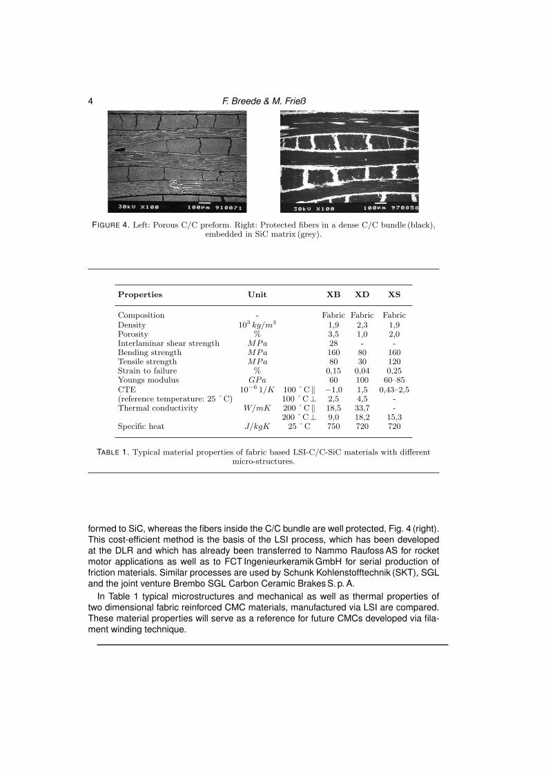
As mentioned before, in C/C-SiC the weak fiber matrix interface is essential to obtaina quasi-ductile fracture behavior. Additionally, the fibers must be protected against directcontact to the high reactivity of the molten Si to obtain characteristic CMC properties,such as high strength, fracture toughness, and thermal shock resistance. Time consum-ing and costly fiber coatings via polymer impregnation of fibers and pyrolysis (PIP) andCVI of fibers are not necessary if particularly suitable precursors are used for manufac-ture of the CFRP preform to provide an in-situ fiber protection. These precursors offer astrong fiber matrix bonding in the CFRP preform, leading to a segmentation of each fiberbundle into dense C/C bundles during pyrolysis, Fig. 4 (left). During the subsequent MI,only the fibers on the outer surface of the C/C bundle are contacted to the Si and trans-
4 F. Breede & M. Frieß
FIGURE 4. Left: Porous C/C preform. Right: Protected fibers in a dense C/C bundle (black),embedded in SiC matrix (grey).
Properties Unit XB XD XS
Composition - Fabric Fabric FabricDensity 103 kg/m3 1,9 2,3 1,9Porosity % 3,5 1,0 2,0Interlaminar shear strength MPa 28 - -Bending strength MPa 160 80 160Tensile strength MPa 80 30 120Strain to failure % 0,15 0,04 0,25Youngs modulus GPa 60 100 60–85CTE 10−6 1/K 100˚C ‖ −1,0 1,5 0,43–2,5(reference temperature: 25˚C) 100˚C⊥ 2,5 4,5 -Thermal conductivity W/mK 200˚C ‖ 18,5 33,7 -
200˚C⊥ 9,0 18,2 15,3Specific heat J/kgK 25˚C 750 720 720
TABLE 1. Typical material properties of fabric based LSI-C/C-SiC materials with differentmicro-structures.
formed to SiC, whereas the fibers inside the C/C bundle are well protected, Fig. 4 (right).This cost-efficient method is the basis of the LSI process, which has been developedat the DLR and which has already been transferred to Nammo Raufoss AS for rocketmotor applications as well as to FCT Ingenieurkeramik GmbH for serial production offriction materials. Similar processes are used by Schunk Kohlenstofftechnik (SKT), SGLand the joint venture Brembo SGL Carbon Ceramic Brakes S. p. A.
In Table 1 typical microstructures and mechanical as well as thermal properties oftwo dimensional fabric reinforced CMC materials, manufactured via LSI are compared.These material properties will serve as a reference for future CMCs developed via fila-ment winding technique.

CMCs for Rocket Nozzles 5
3. CMC Material RequirementsIn order to develop a novel CMC material, the conditions in an operating liquid-fueled
rocket nozzle must be known to define the CMC material requirements. Therefore aspecifications sheet has been compiled which gives an overview on typical conditionsand requirements. It covers the main demands, such as thermal, mechanical and chem-ical loads.
Thermal Loads
The material temperature of a radiation-cooled nozzle extension will be in the range of1300 – 1700 ˚ C [2]. Heat fluxes of about 5–8 MW/m2 are expected. Due to the hightemperature gradients from the inner wall temperatures to the outer wall temperatures,the material has to withstand high thermo-mechanical stresses.
Mechanical Loads
During operation a series of mechanical loads act on the structure of the nozzle exten-sion. During start-up of the engine high side-loads are induced, due to flow transitionsinside a TOC-nozzle (thrust optimized contour nozzle) [3, 4]. These side loads can beas high as 3 % of the specific vacuum thrust and range from 75-120 kN. Furthermore,there is the risk of buckling loads due to the high pressure gradients from ambient to in-ner wall pressure during the start. An other mechanical load is created by the so calledbuffeting. These are fluctuating forces with moderate frequencies of about 20 Hz duringthe trans-sonic ascent.
Chemical Loads
A big issue is the protection of CMCs from oxidation. A serious drawback of carbon fiberreinforced ceramics is that carbon in any form will react with oxygen at temperaturesas low as 500 ˚ C. The main reaction product in liquid fueled rocket engines (LOX/LH2)is water vapor (mt. 95–97%). Water vapor at high temperature (>600 ˚ C) does not onlyreact with carbon fibers and matrix, it also leads to an accelerated SiC recession byoxidation at high water-vapor pressures [5, 6]. The oxidation leads to significant massloss and consequently weakens the material strength properties. Protection coatingslike environmental barrier coats (EBC) and thermal barrier coats (TBC) are inevitableand have to be evaluated in terms of erosion resistance and their adherence to thesubstrate.
The following properties are required for a CMC rocket nozzle material:
(a) Thermal-shock resistance(b) Oxidation resistance in oxygen conditions at high temperatures (>1300 ˚C)(c) Oxidation resistance in water vapor conditions at high temperatures (>1300 ˚C)(d) Erosion resistance to exhaust gases(e) Moderate fracture toughness(f) High temperature strength(g) Sufficient durability for typical operation lifetimes

6 F. Breede & M. Frieß
FIGURE 5. Example of a C/C-SiC panel via filament winding and LSI route.
4. StudiesDue to its cylindrical form the nozzle structure will very likely be manufactured via fil-
ament winding technique or braiding technique. In the first phase of sub-project D7 thegoal is to manufacture a series of C/C-SiC specimens (panels and cylinders) via fila-ment winding technique. In this part of the work the winding technique will be integratedinto the LSI process. In a later stage thermo-mechanical studies will be performed toevaluate the material properties. During the CFRP manufacture a variety of processparameters can influence to microstructure and material properties of the final CMC.
Therefore the following winding process parameters will be investigated:
– Winding angle– Winding pattern– Roving size– Carbon fiber type– Winding speed– Resin-bath temperature
Different geometries are available for sample generation and preparation. Panels andcylindrical specimens will be manufactured in different dimensions. Panels are used toprovide specimens for determination of mechanical properties. Fig. 5 shows a CMCpanel used for tensile test specimens. The tensile specimens are cut in different orien-tations to determine strength values for different fiber orientations. One objective is amaterial database which will give information on how to set the winding process param-eters to receive a desirable CMC material. Typical winding angles for mechanical testingare ± 15, ± 30, ± 45, ± 60 and ±75 degrees.
The determination of the mechanical properties, such as tensile strength and Youngsmodulus, are also carried out at high temperatures (>1000 ˚ C) and after thermal agingin an oxidizing atmosphere.
In addition to the comprehensive thermo-mechanical testings, the C/C-SiC specimensundergo further material testing to determine the erosion resistance in high velocity gasflows at high temperatures. Test campaigns are planned at the cooperating institutesDLR Koln and DLR Lampoldshausen. At DLR Lampoldshausen hot-firing passengertests are planned at the M11 test facility for summer 2010. Panels are placed into the

CMCs for Rocket Nozzles 7
exhaust gas flow which is containing about 10 % of water vapor. The temperature isassumed to be above 1000 ˚ C [7].
In a second test campaign at the high-enthalpy wind tunnels at DLR Koln furthertesting is conducted on erosion and oxidation resistance behavior. The campaign will beperformed in the first half of 2010. Temperatures of about 1000 ˚ C and Mach number of7–8 of hot air flow are the expected test conditions.
Both test campaigns will give a good overview on the materials erosion resistance atmoderate temperatures. The main objective is to study and estimate mass loss rates ofC/C-SiC.
It is attempted to reduce the open porosity of the CMC material to a minimum. Thus,the permeability will be studied. The Darcy-Forchheimer coefficients (kd,kf ) which de-scribe the permeability behavior of a porous material are tested at DLR Stuttgart.
The mechanical damping behavior of C/C-SiC is an additional aspect which will beinvestigated later in this research period.
As mentioned before in section 3, the oxidation behavior of C/C-SiC is an essentialaspect in this research. The thermo-chemical kinetics have to be understood in orderto provide an adequate protection system. In a first step unprotected C/C-SiC referencesamples were used to determine the mass loss in air at different temperatures. Ther-mogravimetry analysis was used to measure the mass loss over time. Fig. 6 shows theresults of the TG-analysis. It is clearly visible that weight loss increases with raisingtemperatures. Depending upon exposure time mass loss stops when all free carbonhas dissipated, leaving the SiC-matrix behind. This led to a total weight loss of about55 % causing strength degradations. This basic experiment shows the sensitivity of stan-dard uncoated C/C-SiC to oxidizing atmospheres. A protection layer in terms of environ-mental barrier coatings (EBC) or thermal barrier coatings (TBC) are indispensable for arocket nozzle application with moderate lifetimes of about 1–2 hours including testingtimes. The reduction of oxidation rates is the main objective for a protection coating sys-tem. Thus, diffusion rates of oxygen into the material have to be reduced. In additionthe silicon based ceramics must be protected against accelerated attack by water-vaporenvironments through oxidation and volatilization reactions.
Beside the material development of C/C-SiC via winding technique there is great at-tention to evaluation of adequate coating systems. Topcoat materials must be stable inwater-vapor pressurized environments at high temperatures. Also, it is important thatthe thermal expansion coefficient is similar to that of the substrate. In addition, the ero-sion resistance as well as the bond of the coating to the substrate has to be tested.Well known examples for topcoats are CVD-SiC and yttria-stabilized zirconia (YSZ) ormulti layer coatings consisting of mullite and BSAS-systems (barium-strontium-alumina-silicate) [8,9].
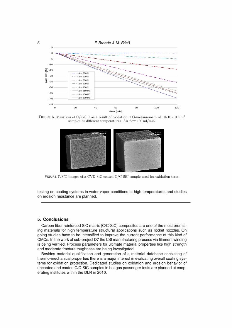
In order to compare the mass loss behavior of uncoated and coated C/C-SiC samplesin oxidizing environment at high temperature, thermogravimetric measurements (TGA)with CVD-SiC topcoat on C/C-SiC samples were conducted. Fig. 7 depicts CT-imagesof the sample at which the topcoat is clearly visible. The thickness of the CVD-SiC pro-tection coat was about 200 µm. A first comparison of un-coated C/C-SiC and coatedCVD-SiC C/C-SiC is shown in Fig. 8. The TG measurement was conducted at 1500 ˚ Cand a constant air flow of 100 ml/s. The sample dimensions were 10x10x10 mm3. Nosevere weight loss is recognized at the CVD-SiC coated samples. The uncoated sam-ple in contrast suffered a major mass loss (35 %) within two hours of the test. Further
8 F. Breede & M. Frieß
-45
-40
-35
-30
-25
-20
-15
-10
-5
0
5
0 20 40 60 80 100 120
time [min]
mas
s lo
ss [%
]
∆m 500°C
∆m 600°C
∆m 700°C
∆m 800°C
∆m 900°C
∆m 1100°C
∆m 1500°C
∆m 1300°C
FIGURE 6. Mass loss of C/C-SiC as a result of oxidation. TG-measurement of 10x10x10 mm3
samples at different temperatures. Air flow 100ml/min.
FIGURE 7. CT images of a CVD-SiC coated C/C-SiC sample used for oxidation tests.
testing on coating systems in water vapor conditions at high temperatures and studieson erosion resistance are planned.
5. ConclusionsCarbon fiber reinforced SiC matrix (C/C-SiC) composites are one of the most promis-
ing materials for high temperature structural applications such as rocket nozzles. Ongoing studies have to be intensified to improve the current performance of this kind ofCMCs. In the work of sub-project D7 the LSI manufacturing process via filament windingis being verified. Process parameters for ultimate material properties like high strengthand moderate fracture toughness are being investigated.
Besides material qualification and generation of a material database consisting ofthermo-mechanical properties there is a major interest in evaluating overall coating sys-tems for oxidation protection. Dedicated studies on oxidation and erosion behavior ofuncoated and coated C/C-SiC samples in hot gas passenger tests are planned at coop-erating institutes within the DLR in 2010.

CMCs for Rocket Nozzles 9
-40
-35
-30
-25
-20
-15
-10
-5
0
5
0 20 40 60 80 100 120
time [min]
mas
s lo
ss [%
]
∆m 1500°C coated
∆m 1500°C
FIGURE 8. Comparsion of mass loss of CVD SiC coated C/C-SiC and uncoated C/C-SiC viaTG-measurement.
AcknowledgmentsFinancial support has been provided by the German Research Council (Deutsche
Forschungsgemeinschaft - DFG) in the framework of the Sonderforschungsbereich Trans-regio 40. Computational resources have been provided by the Stuttgart High-PerformanceComputing Center (HLRS).
References[1] HEIDENREICH B., LUTZENBERGER N., VOGGENREITER H. Carbon Fiber Rein-forced Ceramics in Carbon Fibers Reinforced Composites, Ullmanns Encylopediaof Industrial Chemistry Electronic Release 2009, page: 78–111, ISBN 978-3-527-32445-3.[2] ALTING J., GRAUER F., HAGEMANN G., KRETSCHMER J. (2001). Hot-Firing ofan Advanced 40 kN Thrust Chamber. AIAA 2001-3260[3] HAGEMANN G., TERHARDT M., HAESLER D. (2002). Experimental and Analyt-ical Design Verification of the Dual Bell Concept. Journal of Propulsion an Power,Vol. 18, No. 1 Jan-Feb 2002.[4] HAGEMANN G., FREY M. (2002). Appearance of Restricted Shock Separation inRocket Nozzles. Journal of Propulsion an Power, Vol. 18, No. 3 May-Jun 2002.[5] DENG J., LIU W., DU H., CHENG H., LI Y. (2001). Oxidation Behavior of C/C-SiCGradient Matrix Composites. J. Material Sci. Technol.}, Vol. 17, No. 5 2001.[6] EATEN H., LINSEY G. (2002). Accelerated oxidation of SiC CMCs by Water Va-por and Protection via Enviromental Barrier Coating Approach. J. of the EuropeanCeramic Society, 22, 2741-2747.[7] STARK R., GENIN-NRNBERGER C. (2009). Personal Communication DLR Lam-poldshausen.[8] MORE K., KIMMEL J., EATON H. (2002). Evaluating EBCs on CMCs after Enigneand Laboratory Exposure. Proceedings of ASME Turbo Expo 2002, GT-2002-30630.[9] NAKAYAMA H. (2006). Evaluation of EBCs for SiC CMCs. Advanced CeramicCoatings and Interfaces, 30th IC on Advanced Ceramics and Composites, Jan 2006,FL,USA.