Development of active camera stabilization system for ...
53
Development of active camera stabilization system for implementation on UAV’s Author: Eduardo Ansias Carmona Final thesis of Aeronautical engineering (Air navigation) Supervisor: Domantas Brucas Department: Mechanics Date: June 2012
Transcript of Development of active camera stabilization system for ...

Development of active camera stabilization system for
implementation on UAV’s
Author: Eduardo Ansias Carmona
Final thesis of Aeronautical engineering (Air navigation)
Supervisor: Domantas Brucas
Department: Mechanics
Date: June 2012

Development of active camera stabilization
system for implementation on UAV's
1
Padėka
Noriu išreikšti nuoširdžią padėką Antano Gustaičio aviacijos
institutui ir Vilniaus Gedimino Technikos universitetui, kurių
pagalba buvo parašyta ši disertacija.
Be to, dėkoju savo darbo vadovui Domantui Brukui už
vertingus patarimus ir konsultacijas atliekant darbą.
Taip pat šiai šaliai, parodžiusiai didžią kultūrą ir tradicijas. Ačiū
Lietuvai už suteiktą gerą mokymosi aplinką ir priemones savęs
ugdymui bei naudingą patirtį, kuri visada išliks mano atmintyje.
Galiausiai, dėkoju savo universitetui, Katalonijos politechnikos
universitetui, už šią galimybę, leidusią man tobulėti savo
profesinėje karjeroje.

Development of active camera stabilization
system for implementation on UAV's
2
Acknowledgements
I would like to express my sincere gratitude toward the
Antanas Gustaitis Aviation Institute and Vilnius Gedimino
Technikos Universitetas under the wings of which the work
behind the current thesis was carried out.
Further, I would like to thank my supervisor Domantas Brukas,
who supported me during the process, for the valuable
guidance and advice.
I also would like to thank the great culture and traditions that
this country shows. Thanks Lithuania for providing me with a
good environment and facilities to improve myself as well as
get fruitful experiences which always will be in my mind.
And last but not least, my university, Polytechnic university of
Catalonia (UPC), for offering me this opportunity which has let
me be better in my professional career.

Development of active camera stabilization
system for implementation on UAV's
3
INDEX
0. Abstract ............................................................................................... 4
1. Introduction ......................................................................................... 5
2. Analysis of available equipment ........................................................... 6 a. UAV ....................................................................................................... 6 b. Camera .................................................................................................. 7 c. Mechanical system ............................................................................... 7
i. Vibration ................................................................................... 8 ii. Jolting ........................................................................................ 8
iii. Materials ................................................................................... 8 iv. Swinging .................................................................................... 9 v. Bearings .................................................................................... 9
vi. Servos ..................................................................................... 10 d. Control system .................................................................................... 10
i. Multi-Rotor Control Board ..................................................... 10 ii. ArduPilot Board ...................................................................... 12
e. Some solutions ................................................................................... 13 i. Gimbals Mechanism ............................................................... 13
ii. Movement mechanisms ......................................................... 14
3. Calculation of needed parameters and data ....................................... 15 a. Servos ................................................................................................. 15
i. Servo 1 .................................................................................... 16 ii. Servo 2 .................................................................................... 20
b. Bearings .............................................................................................. 25 i. Bearings 1&2 (Y axis) .............................................................. 25
ii. Bearings 3&4 (X axis) .............................................................. 26 c. Structure ............................................................................................. 27
i. Type of material ...................................................................... 27 ii. Calculation of the Thickness ................................................... 30
1. Thickness of the structure #1 ..................................... 31 2. Thickness of the structure #2 ..................................... 33
d. Shock absorbers .................................................................................. 37
4. Constructing of the equipment and guidelines.................................... 39 a. Constructing planes ............................................................................ 39 b. Instructions ......................................................................................... 45
5. Conclusions ........................................................................................ 50
6. References ......................................................................................... 52

Development of active camera stabilization
system for implementation on UAV's
4
0. Abstract
This project is based on a mechanical design of a system to control the movement of a
camera located within a non- manned aerial vehicle. The pieces which are involved in
the dispositive assembly must be designed in order to comply to the aircraft model
properly. Furthermore, it is necessary to include a system to get camera stabilization
as well as absorption of the vibrations whether a good quality pictures is reached.
Initiating the project, the available dispositive and the characteristics which those are
provided are going to be shown in this study. Moreover, analyses on the mechanisms
and solutions which can be found currently have been done as well as a comparison
between all of them toward to define which dispositive would be adapted to our
requirements. In particular, the system that is presented here and it has been designed
could be able to effectuate a rotation which comprises a range from 20º to -20º in the
axes X and Y, providing the camera of a major visual area. On the one hand, the
movement is carried out by the servos which are the active elements in charge to the
camera rotation whereas the rest of the systems such as shock absorbers or mobile
arms result to be the passive mechanism.
In addition a programmable controller board has been used in order to get a control of
the servos in both axes X and Y among other utilities such as GPS or maneuver the
aircraft.
Furthermore, necessary calculations have been done to determine the thickness of the
pieces which are bearing the camera, to identify what would be the right material to
use, the torque of the servos or in order to specify what kind of shock absorbers are
necessary in the device.
Once the system has been validated, a 3D design is performed to get an overview of
how will the mechanism be. Later, all of the construction drawings of pieces and parts
are drawn as well as its assembly instruction manual.

Development of active camera stabilization
system for implementation on UAV's
5
1. Introduction
An UAV (unmanned aerial vehicles) is an aircraft which operates without tribulation on board. There is no single model of these devices, can vary in shape, size, configuration, missions, etc.
The history of UAVs began after the First World War where the design of the first prototypes of unmanned aerial vehicles started. These prototypes would be used later in the Second World War. In late twentieth century, thanks to the technological advances, these devices controlled by radio control (Drones) got full autonomy.
Today the UAVs are systems capable of operating without human intervention (takeoff, route and landing are automatic). Actually these vehicles can capture large amount of information as was demonstrated in the Gulf War or the war in Bosnia due to the cameras, sensors or microphones installed inside and controlled or not from the ground station. The great advantage of these devices is their ability to be used in conflict areas or inaccessible due to its autonomous system and its low cost compared with other manned aircraft. Currently, UAVs are used in military reconnaissance missions or attack and civilian applications such as cooperation in drug control, terrorism, fire fighting, maritime piracy or civil security through images and videos of their movements. It is possible also use these devices in environments highly toxic and radioactive chemicals such as what happened at the Chernobyl nuclear power plant in 1986, namely in places where human life is endangered and it is necessary take samples to study the affected area.
In addition to mechanics and flight control electronics such as the elevator, rudder, flaps etc. or the electronic system, an UAV is characterized by the data acquisition systems installed on board. These include: temperature sensors, pressure, chemical composition, sound, photographic imaging, video and so on. In this project, we will focus essentially on the image capture system and its control system.
Fig #1 TDD (Target Drone Deny 1)

Development of active camera stabilization
system for implementation on UAV's
6
2. Analysis of available equipment
The first task we have to complete is a research about all available components or
devices that we can use for build our active camera stabilization system.
UAV:
This UAV have a two-stroke piston valve petrol aircraft engine, and have a
displacement of 55cc (27.2ccx2) and RPM Range between 1600-7800rpm. The engine
uses a propeller with two blades.
Fig #2 Available unmanned aerial vehicle
Fig #3 Section and dimensions of the UAV

Development of active camera stabilization
system for implementation on UAV's
7
Camera:
The available camera for the project is a Canon EOS 550D SLR camera with an
approximate weight of 540 g. This model is able to capture still images and videos Full
HD (1080p).
Our image capture system should consist of a mechanical system which is responsible
of execute all the movements, and a control system which send the movement
information to the mechanical system.
Mechanical system:
Since the camera system will be onboard in our UAV and the aircraft will be in constant
movement, will appear instability in the three axes of motion. This instability will be
reflected in unwanted vibrations or image rotations. Therefore, the first design step
will be finding a solution to these instabilities through a series of damping devices.
There are three kinds of undesirable movements that should be considered in our
study: Vibration, jolting and Swinging. We will explain how they occur and what
solutions we can find for apply in our project. It is necessary a combination of these
solutions in order to have a correct stabilization system. Each one of them eliminates
an undesirable movement or vibration. So, is not possible apply only one solution in
order to fix all the unstable problems.
Fig #4 Canon EOS 550D SLR Camera

Development of active camera stabilization
system for implementation on UAV's
8
Vibration:
This oscillation occurs as a result of the operation of
the engines and mechanical joints moving. So, is
impossible reduce this undesired movement without
any kind of device. To avoid or reduce the
transmission of this oscillation to the camera system,
shock-absorbers can be used. There are various types
such as rubber or silicone and they can be found in
specialty stores
Jolting:
This kind of movement may occur because of a sudden gust of wind or turbulence. To
solve this problem dampers are also used but in
this case consist of a spring and a piston oil or
tire. This type of damper is similar to those that
are installed in cars and the operating principle
is the same: when a car passes through a
mountainous surface, absorbs jerky movement
of the wheel and prevents the transmission to
the chassis of the car. Similarly, when a gust of
air destabilizes the aircraft, the damper prevents
the transmission of this movement to the
camera.
Materials:
Because of the load is a limitation for the UAVs, we have to looking for resistant and
light materials to build all the control mechanism
of the camera. Also, the materials should to have
a good formability and malleability in order to be
possible build all the pieces with a correct shape
and without any crack in its structure. The
mechanism will be most of time outside, so the
corrosion resistance is required too. Some good
candidates suitable for construction are the
carbon fiber and aluminum.
Fig #5 Examples of Shock-absorbers
Fig #6 Dampers to prevent the jolting
Fig #7 Aluminum pieces

Development of active camera stabilization
system for implementation on UAV's
9
Swinging:
It occurs as a result of maneuvering the aircraft during flight. The most efficient way to
prevent this movement is through the use of
gyroscopes o gimbals. The gyroscope is a
mechanical device consisting of a rotationally
symmetric body which rotates around its axis
of symmetry. To understand the physical
functioning we can take the example of a
cyclist. When he takes a curve, he is inclined
along with the bicycle towards the curve
center. The higher the speed, the rotation of
the handlebars is less and greater the
inclination that can be taken with respect to
the vertical. This is the foundation of the
movement of the gyroscope, a device
invented in 1852 by Leon Foucault to demonstrate the rotation of the Earth. This
device is a spherical object, or disc shaped, mounted on a support that can rotate
freely in any direction. It is used to measure the orientation or to maintain it, because
of its operation being based on the principle of conservation of angular momentum.
There are numerous applications, such as to reduce the rolling of ships, to stabilize
platform, the suspension of helicopters or like a compass
In our project, the available space inside of the UAV maybe is not enough actually
would be difficult to install a gyroscope considering its size. Perhaps we could consider
how to install the camera outside of the aircraft or design a smaller gyroscope.
Bearings:
The bearings are used to minimize friction between two
moving surfaces. This allows and promotes free rotation
around a fixed axis or free linear movement. There are three
basic types: ball bearings, roller bearings or needle roller
bearings.
They could be very useful if they are installed in the rotation
axis of the camera (in X and Y direction) since the movement
would be much smoother and continued.
Fig #8 Example of gimbals
Fig #9 Bearings

Development of active camera stabilization
system for implementation on UAV's
10
Servos:
A servo is a device similar to a DC motor which has
the ability to be located at any position within its
range of operation, and remain stable at that
position. Comprises an electric motor and has the
ability to be controlled, both in speed and position.
Servo systems are often used in radio control and
robotics, but their use is not limited to these.
The servos uses pulse-width modulation (PWM) to
control the direction or position of the DC motors.
Most of the servos works with fifty hertz frequency
and the PWM signals have a twenty milliseconds
period. The electronics inside the servo responds to the width of the modulated signal.
If the circuits inside the servomotor receive a signal from 0.5 to 1.4 milliseconds, this
will move clockwise, from 1.6 to 2 milliseconds move the actuator counter-clockwise,
1.5 milliseconds represents a neutral state for the standard servos.
Control system:
Another option to stabilize the camera is using a control board. We will present two
examples of these boards to compare:
Active stabilization with the Multi-Rotor Control Board V3.0 (Atmega328 PA):
The Multi-Rotor control is a flight control board for multi-rotor Aircraft (Tricopters,
Quadcopters, Hexcopters).
Fig #11 Examples of control signals used and their respective results of servo position. The servo position
has a linear proportion to the pulse width used.
Fig #10 Example of a servo

Development of active camera stabilization
system for implementation on UAV's
11
Its purpose is to stabilize the aircraft during flight. This board collects information from
three gyroscopes installed on the same board (roll, pitch and yaw) and analyzes it with
a processor unit (Atmega328PA IC.). This unit is programmable and can be configured
according to our needs, in our case, could control the servo motors to keep the camera
steady. The HobbyKing Multi-Rotor control board uses “Japanese Murata piezo gyros”
that are less sensitive to vibration than SMD type gyros and also features state of the
art SMT manufacturing to ensure quality. The board also uses signals from your radio
systems receiver (Rx) and passes these signals to the Atmega328PA IC via the ail, ele,
thr and rud inputs. Once this information has been processed the IC will send varying
signals to the ESCs which in turn adjust the rotational speed of each motor to induce
controlled flight (up, down, backwards, forwards, left, right, yaw).
Some specifications:
- Size: 50.5mm x 50.5mm x 23.5mm
- Weight: 14.5 gram
- IC: Atmega328 PA
- Gyro: Murata Piezo
- Input Voltage: 3.3-5.5V
- Signal from Receiver: 1520us (4 channels)
- Signal to ESC: 1520us
Maybe this method is not effective because of we need absolute attitude reading
instruments (like accelerometers or magnetometers) and this board only have
gyroscopes.
Fig #12 Multi-Rotor Control Board V3.0

Development of active camera stabilization
system for implementation on UAV's
12
ArduPilot Board - Arduino Compatible UAV Controller w/ ATMega328:
ArduPilot is an Arduino-compatible autopilot board
designed by Chris Anderson and Jordi Muñoz of DIY
Drones using the new ATMega328.
ArduPilot is a fully programmable autopilot that requires
a GPS module and infrared XY and Z sensors to create a
functioning Unmanned Aerial Vehicle. The autopilot
handles both stabilization and navigation, eliminating the
need for a separate stabilization system. It also supports a
"fly-by-wire" mode that can stabilize an aircraft when
flying manually under RC control, making it easier and
safer to fly. The hardware and software are all open source. The board comes with all
the surface-mount parts already soldered, but requires the user to solder on
connectors. Firmware is already loaded, but the autopilot software must be
downloaded and loaded onto the board by the user. It can be programmed with the
Arduino IDE. ArduPilot uses infrared (thermopile) sensors or an IMU for stabilization
and GPS for navigation.
ArduPilot features include:
- It can be used for an autonomous aircraft, car or boat.
- Built-in hardware failsafe that uses a separate circuit (multiplexer chip and
ATTiny processor) to transfer control from the RC system to the autopilot and
back again. Includes ability to reboot the main processor in mid-flight.
- Multiple 3D waypoints (limited only by memory)
- Altitude controlled with the elevator and throttle
- Comes with a 6-pin GPS connector for the 4Hz uBlox5 or 1hz EM406 GPS
modules.
- It has six spare analog inputs (with ADC on each) and six spare digital
input/outputs to add additional sensors
- Supports addition of wireless modules for real-time telemetry
- Based on a 16 MHz Atmega328 processor. Total onboard processing power
aprox 24 MIPS.
- Size: 30mm x 47mm
- Can be powered by either the RC receiver or a separate battery
- Four RC-in channels (plus the autopilot on/off channel) can be processed by the
autopilot. Autopilot can also control four channels out.
Fig #13 ArduPilot Board

Development of active camera stabilization
system for implementation on UAV's
13
We can find some compatibles items for this board in the seller’s web page:
- An EM406 GPS module
- An Expansion Board with airspeed sensor
- XY and Z sensors
In this case, this board is perfectly compatible not only with our mechanism but also with other systems on board. We could use this board to control the control surfaces of the aircraft, GPS system, camera system, etc.
Some solution:
First of all we going to do a research of some solutions from other projects to analyze them and compare them. By this way, we will find the best mechanism to build our active camera stabilization system.
- Gimbals Mechanism:
It is the most popular solution for helicopters. With this type of mechanism we have several disadvantages. The size of these devices is usually quite large in comparison with other solutions; the cost and complexity of design are high. This mechanism is ideal for use on helicopters because of they work with propellers and do not depend of the wing surfaces to stay in the air as occur with UAV with wings.
If we use this device in our project we will have a large parasitic resistance. This means the aircraft consume more fuel to keep itself in the air so the flight time would be reduced considerably. Another major drawback is the camera will be completely uncovered, this means that in rainy or snowy days cannot take pictures. Furthermore dust particles suspended in air could damage the camera lens. On the other hand, our airplane does not have enough space between its structure and the landing gear. As we can see on the picture, this kind of mechanism needs a big space to install and this means, a higher landing gear. If we chose this kind of mechanism, we would have to change our landing gear system and we will have again more parasitic resistance and more weight.
Fig #14 Helicopter with gimbals system
Fig #15 Quadrocopter with gimbals system

Development of active camera stabilization
system for implementation on UAV's
14
-Movement mechanisms:
Arm system:
The figure number 14 shows a solution to move vertically the platform where the camera is installed. This mechanism is not a bad solution but we can observe that do not exist any kind of vibration absorption. The servos have stepping motion, they move in certain rapid angular steps because of the limitation of their potentiometers. This effect can be reflected with undesirable movements on the recording images. So, it is possible use the basic principle of the mechanism but we have to do modifications which can be add springs or dampers in order to eliminate the vibrations produced by the servos.
Springs:
Use of springs is a good one solution for our project. If there are springs installed between the servo which moves the platform where is installed the camera and the fixed platform, not only it will be reduced considerable the vibration but also it will not be necessary use any reducer to increase the servo's torque. The reducer lowers the speed of rotation of the platform of the camera when the servo has an excessive torque. With excessive torque, appear swinging movements on the platform and these movements are not desired. With springs installed on the mechanism it is possible to reduce this effect. For example: if the camera platform is displaced by the servo out of its equilibrium position and after the servo comes back, if the servo has an excessive torque, the platform oscillates until come back to its equilibrium position. The springs absorbed this oscillation doing a movement more smoothed and flowed.
There are different types of springs: tension springs, compression and torsion. The choosing of one type or another depends of what kind of force will act on the spring. So, we should have to take into account what forces are acting when the servo is pushing the platform of the camera in order to choose the correct spring.
Fig #16 Arm system to move the
camera vertically
Fig #17 Moving mechanism of the camera using springs

Development of active camera stabilization
system for implementation on UAV's
15
Elastic bands:
The elastic bands are a good solution to absorb the vibration caused by the work of the servos. This system is very easy to construct and also cheap but, have an important problem. The elastic band are degraded because of the time, this produced
a change in the elastic coefficient and the properties of the material. This means that the mechanism does not work the same way along the time. The sun rays and the hot environments can crack the elastic band and it could break. So we can use this solution but requires maintenance along the time and this is an important disadvantage. For this reason we will not use this devices, we have to looking for another solution in order to have more durable system.
3. Calculation of needed parameters and data
Servos:
We will consider for the movement of the servos, a maximum angular speed in range of 10deg/sec.
Normally, the angle of rotation of the servos is up to +/-90 deg or +/- 45-60 deg. In our project we need a maximum rotation around +/- 10 deg or +/- 20 deg. Consequently we have to decrease the angle of rotation of the servos with some device like an arm.
So, the starting point is determining the longitude of the servo arm and the plate arm. We consider that when the servo rotates 60º, the camera has to rotate only 20º. In the mechanism, we have two different servos in different positions, one of them moves the camera in the X axis and the second servo moves it in the Y axis. In addition, the servo 1 has to have less torque than the servo 2 because the weight that has to lift up is less.
The springs which absorbs the vibrations of the servos when they rotates, have to be of compression and traction at the same time. When the servo is in a position, one of the springs works in traction and the other in compression, when the servo change its position in the opposite direction, the springs works oppositely too.
Fig #18 & Fig #19: Examples of using elastic bands on the camera stabilization system
Fig #18
Fig #19

Development of active camera stabilization
system for implementation on UAV's
16
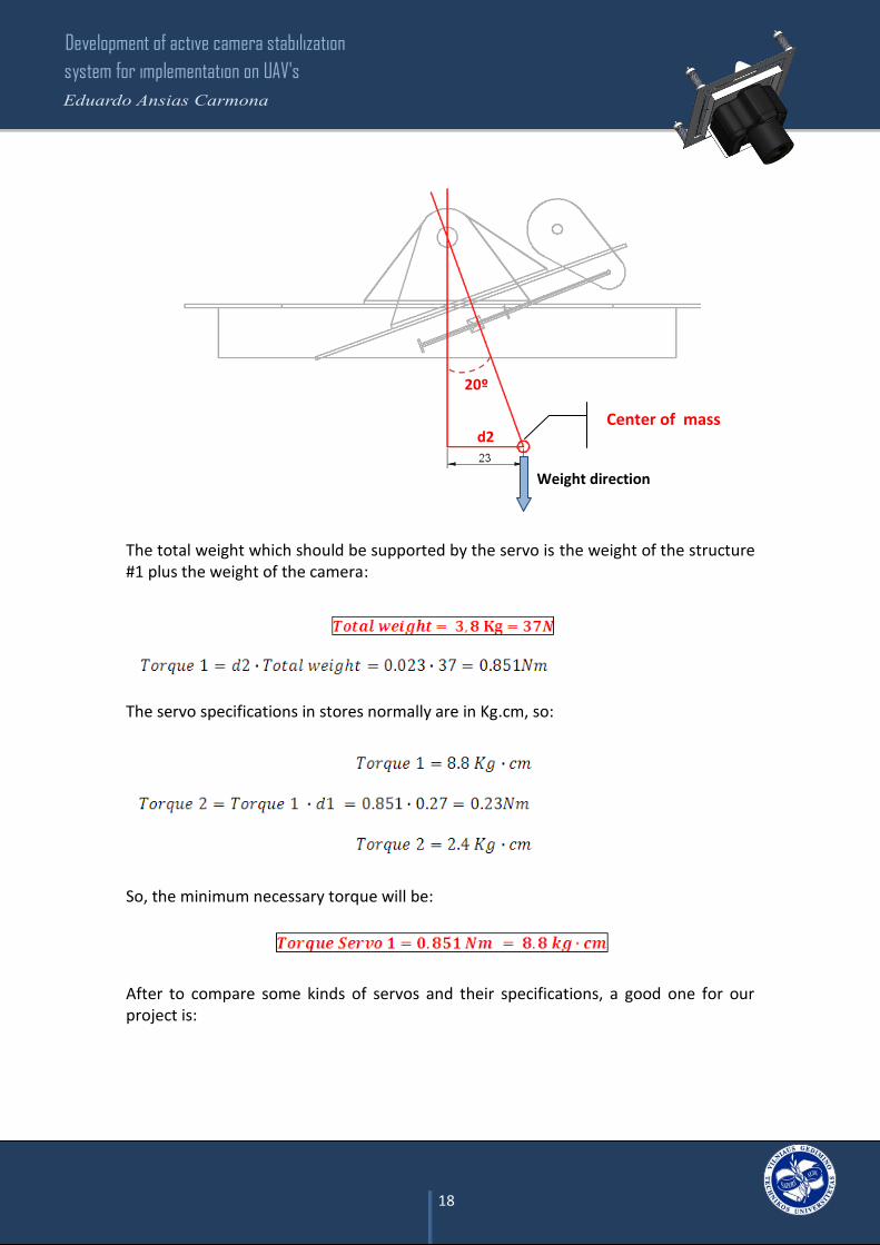
Servo 1:
Movement schemes:
- Equilibrium position:
- + 20º:
APPLIED FORCE
Fig #20: Position of the servo 1 in the mechanism

Development of active camera stabilization
system for implementation on UAV's
17
- - 20º:
Necessary servo:
Real wiught Struct 1 = 713 g
We consider a G force of: N= 3g so the total weight we have is three times the real weight:
Total Struct 1 weight = 2.14 Kg = 21 N
The weight of the camera is 540 g, so if we consider the G force:
Total Camera weight = 1.62 Kg = 16 N
In order to calculate the correct servo, is necessary to know where the center of mass of the weight is.
d1 = 7/27 = 0.27
Struct 1
Camera
APPLIED FORCE
Weight direction
Center of mass
Development of active camera stabilization
system for implementation on UAV's
18
The total weight which should be supported by the servo is the weight of the structure #1 plus the weight of the camera:
The servo specifications in stores normally are in Kg.cm, so:
So, the minimum necessary torque will be:
After to compare some kinds of servos and their specifications, a good one for our project is:
Center of mass
Weight direction
20º
d2

Development of active camera stabilization
system for implementation on UAV's
19
BMS-990DMG Low Profiled Coreless motor Digital Servo (All Metal Gear) 9.0kg / .09sec / 45g:
Some specifications:
The servo will automatically learn the users transmitter pulse timings and lock into the signal every time. The servo also includes a signal buffer in the CPU with fail-safe functionality. The motor is wound with 2PEW thin coated wire for better electrical conductivity and is able to withstand high temperature without degradation. The servo comes with an accessory package and the universal JR/Hitec "S" Connector which is physically and electrically compatible with all major receiver brands sold worldwide.
1. Double M9.6 ball bearing (si-oil) 2. 3 pole high-torque motor with low RF noise (CE certified) 3. Rubber seals for waterproof case 4. Futaba compatible 25 tooth output splines 5. Heavy duty servo case 6. Integral heat sink 7. Digital motor drive with ultra-square PWM signal 8. Automatic determination of servo center pulse width 9. Metal gears of aluminum 6061 material combined with light and strong C95
material 10. Fail-Safe function 11. 2PEW coated motor wire for high-temperature use 12. Digital control IC - SOP package with 12bit data transfer 13. MOS-FET motor driver chips that can handle 7A peak loads 14. Torque At 6.0V: 9.0kg/cm , 125 oz/in 15. Speed At 6.0V: 0.09 sec / 60° at no load
It is possible buy this servo on http://www.hobbyking.com web page. This device is only an example of what kind of specifications should have the real servo which will be installed in the mechanism.
Weight (g) 45
Torque (Kg) 9 Speed (Sec/60deg) 0.09 A(mm) 30 B(mm) 42 C(mm) 25 D(mm) 21 E(mm) 54 F(mm) 17
Fig #21: Servo BMS-990DMG

Development of active camera stabilization
system for implementation on UAV's
20
Servo 2:
Movement schemes:
- Equilibrium position:
- + 20º:
APPLIED FORCE
Fig #22: Position of the servo 2 in the mechanism

Development of active camera stabilization
system for implementation on UAV's
21
- - 20º:
Necessary servo:
In this case, the structure #2 is composed for the structure #1 and other pieces so; the weight which the servo has to support is increased.
We consider a G force of: N=3g so the total weight we have is three times the real weight:
The weight of the camera is 540 g, so if we consider the G force:
d1= 20/29 = 0.7
Struct 2
Camera
APPLIED FORCE
Center of mass
Weight direction

Development of active camera stabilization
system for implementation on UAV's
22
The total weight which should be supported by the servo is the weight of the structure #1 plus the weight of the camera:
The servo specifications in stores normally are in Kg.cm, so:
So, the minimum necessary torque will be:
After to compare some kinds of servos and their specifications, a good one for our project is:
Center of mass
Weight direction
20º
d2

Development of active camera stabilization
system for implementation on UAV's
23
BMS-630MG Super Strong Servo 13kg / .17sec / 49g:
Some specifications:
The servo comes with a servo accessory package and is made with a heavy duty servo case; the servo is designed for R/C high performance Car applications. Double ball bearing with flexible rubber waterproof. The output spline is the same as the Futaba 25 tooth. This servo comes with JR/Hitec S Connector also known as a "Universal Connector". Even thought this servo comes with JR/Hitec S Connectors, this servo is electrically compatible with Futaba receivers.
1. Metal gear 2. Curve gear with smooth. 3. Double M9.6 ball bearing (si-oil) 4. 3 pole strong torque of motor with low signal affect and success get CE
certification. 5. Rubber fitting case for waterproof 6. Same with Futaba 25 tooth spline 7. Heavy duty servo case
It is possible buy this servo on http://www.hobbyking.com web page. This device is only an example of what kind of specifications should have the real servo which will be installed in the mechanism.
Weight (g) 49
Torque (Kg) 13 Speed (Sec/60deg) 0.17 A(mm) 30 B(mm) 40.5 C(mm) 25 D(mm) 20 E(mm) 42 F(mm) 17
Fig #23: Servo BMS-630MG

Development of active camera stabilization
system for implementation on UAV's
24
The plate #3 will be fixed with the shock absorbers and the plates #1 and #2 will rotate in different axis by the servos. Both plates can rotates at the same time in different positions, is not necessary rotate one of them and then the other. The servos are controlled by the control system board which sends the electric impulses. This board must be programmed to get a right control of the position.
An antenna will be installed inside of the UAV in order to get a control by ground station or by radio control. There is a big difference between them, if we want to monitoring the UAV by a ground station, the transmitted power must be very high because of the distance between the aircraft and the ground station. Moreover, the capacity of transmission of the UAV have to be higher, this it means that its consumer is higher as well. In conclusion, the autonomy of the aircraft will depend of its maximum distance to transmit and receive. So, normally this solution is used to large distances with heavy
UAVs because of they need a fuel tank bigger and a battery with more capacity.
The second option is use a remote control. The disadvantage is that the operating distance of the UAV is smaller because of the transmitted power by the remote control is low. However the aircraft can keep itself flying a long time, the battery is smaller and the fuel deposit too. So, this is a good one option if the mission of the UAV is close to the control station.
In conclusion the most important aspect that is necessary to check is the necessities of the missions not only to know the consuming of the UAV but also the capacities of its batteries.
Fig #24: Mechanism with rotation
Fig #25: Possibilities of Transmission

Development of active camera stabilization
system for implementation on UAV's
25
Bearings
In order to have a smooth movement, we will need bearings in the movement points. In our mechanism, there are four movement points so, it will necessary two bearing for the X axis and two for Y axis. Bearings 1 & 2 (Y axis):
The total weight supported by the bearings is 3.8 Kg. It means that each bearing have to support half of the total weight that is, 1.9 Kg.
The load ratings of the bearings usually are in kN. So, in this case the minimum load supported by one bearing should be 19 N.
After to look for information about what kind of bearings could be better to use in this project, we have found a good option: Deep groove ball bearings, single row, shield on both sides:
W= 3.8 Kg
Bearing 1 Bearing 2
Fig #26: Example of a bearing

Development of active camera stabilization
system for implementation on UAV's
26
If we pay attention to the specifications, we can see that the load capacities are higher than the ratings we need. The dimensions of this device are very small because of; the load capacity is a function of the dimensions. So, if we want to find a bearing which conforms to specific load ratings, the size of the bearing could be too small and very difficult to find it. Bearings 3 & 4 (X axis):
The total weight supported by the bearings is 5.7 Kg. It means that each bearing have to support half of the total weight that is, 2.9 Kg or what is the same 28 N. So the bearings calculated before for the Y axis, are adequate for the X axis. The load that they will support is only 28 N and the maximum static load that these devices can support is 180 N.
Bearing 3 Bearing 4
W=5.7 Kg

Development of active camera stabilization
system for implementation on UAV's
27
The structure:
Type of material:
Finally, the material that we will use is the aluminum. It is ideal to support the whole structure and the weight of the camera because of its high strength. Its low density allows not exceeding the maximum load that the aircraft can carry and this is an advantage if we want to install another systems.
Some features of this material:
- Density: 2698,4 kg/m3
- Electrical conductivity: 37,7 × 10⁶ S/m
- Thermal conductivity: 237 W/(K·m)
- Elastic modulus: 70 GPa
- In its pure state has a limit of traction strength of 160-200 N/mm2 (160-200 MPa)
The aluminum can be alloyed with a lot of materials which improves its characteristics. Below, it shows the most common aluminum alloys, its advantages and its applications.
Alloys: technical information: -1XXX: Aluminum alloy with 99% purity -2XXX: Aluminum alloy with copper -3XXX: Aluminum alloy with manganese -4XXX: Aluminum alloy with silicon -5XXX: Aluminum alloy with magnesium -6XXX: Aluminum alloy with silicon - magnesium -7XXX: Aluminum alloy with zinc
- Non thermally treatable alloys:
1100
It is commercially pure aluminum (99.00% minimum). It has excellent corrosion resistance, formability, weldability and has high thermal conductivity. It has a tensile strength in the range of 14.000 to 24.000 psi.
APPLICATIONS: Some uses are deep drawing, turning, sheet metal work for decorative or architectural, tins and cans, decorative panels, air ducts, fan blades, etc.

Development of active camera stabilization
system for implementation on UAV's
28
3003
This alloy with 1.2% manganese provides a tensile strength in the range of 17.000 to 30.000 psi. Excellent formability, weldability and corrosion resistance.
APPLICATIONS: Some uses are stamping, turning, gas tanks, and pieces which requires greater resistance than alloy 1100.
5005
This alloy with 0.8% magnesium provides a tensile strength in the range of 18.000 to 30.000 psi. Excellent formability, weldability and corrosion resistance. Specific for similar applications to those of alloys 1100 and 3003 where the anodized finish is required. The anodized finish is similar to the alloy 6063.
5052
This alloy with 2.5% magnesium provides a tensile strength in the range of 31.000 to 44.000 psi. Very good corrosion resistance, good formability, weldability and toughness.
APPLICATIONS: Aircraft fuel tanks, removable covers for windows, refrigerator covers, cooking utensils, boards and electronic assemblies, fan blades.
5083
This alloy with 4.45% magnesium, 0.65% manganese and 0.15% chromium provides a tensile strength in the range of 40.000 to 59.000 psi. It is light because of its weight and has a good resistant to corrosion.
APPLICATIONS: For structures where high efficiency in the weld is required in order to have a very strong bond. Boat parts, stands for trucks, construction equipment, tanks, scaffolding, drilling rigs and cryogenic applications.
5086
This alloy with 4.0% magnesium, 0.45% manganese and 0.15% chromium provides a range of tensile strength between 40.000 to 54.000 psi. Provides additional corrosion resistance and improved the atmospheric corrosion resistance.
APPLICATIONS: Tanks, maritime components, and welded assemblies.

Development of active camera stabilization
system for implementation on UAV's
29
5454
This alloy with 2.7% magnesium, 0.8% manganese and 0.12% chromium provides a range of tensile strength between 36.000 to 47.000 psi. Good formability, weldability and corrosion resistance.
APPLICATIONS: pressure vessels (approved under code ASME for temperatures above 400 ° F), tanks, loading elements for dump trucks, welded structures.
- Thermally treatable alloys
2024
This alloy with 4.5% copper provides a range of tensile strength between 30.000 to 63.000 psi. Very good machinability and corrosion resistance. Forming operations are limited.
APPLICATIONS: Structures subjected to great effort and aerospace applications.
6061
This alloy with 1.0% magnesium and 0.6% silicon provides a range of tensile strength from 20,000 to 42,000 psi. Good formability, weldability and corrosion resistance. Good mechanical strength and electrical conductivity.
APPLICATIONS: Used for engineering and structural applications, boats, furniture, load elements in transportation equipment, wires for electrical conductors, and profiles for architectural and industrial use which requires a higher mechanical strength than the alloy 6063.
7050
This alloyed with zinc (5.7-6.7%), Copper (2.0-2.6%) and Magnesium (1.9-2.6%) provides a superior strength, improved corrosion resistance and strength.
APPLICATIONS: Aerospace and missile applications.
7075
Heavily alloyed with Zinc and low amount of Manganese, copper and chromium. One of the most resistant aluminum alloys, are used in parallel with the 2024 and 7075 is selected when requiring high mechanical properties. Forming operations are limited.

Development of active camera stabilization
system for implementation on UAV's
30
QC-7
This aluminum alloy is very strong, is fully heat treatable. Has outstanding thermal conductivity with high strength and hardness in its surface. Is suitable for polishing and give other textures.
APPLICATIONS: Used for producing plastic injection molds, molds for glass and structural molds for foam, is weldable and very machinable.
- Molten aluminum plate
M-1
With an extraordinary density, this aluminum behaves stable over the entire surface, specifically designed to be plastically molding to high temperatures. Can be inspected by ultrasound 100% for ensure that is free porosity.
It has a superior machinability and high hardness in the Brinelli's scale without heat treatment, which makes this type of plate a great alternative in cost savings and a good solution because of the variety of applications that can give.
So, after to compare their specifications between them, the best option to choose is the aluminum alloy with silicon-magnesium (6061). It provides a good formability, weldability, corrosion resistance and a good mechanical strength. The mechanism will be the most time in the outside, so the corrosion resistance is essential. The vibrations, the abrupt movements or oscillations demand a good mechanical strength so this alloy is a good one election to meet these needs.
Calculation of the Thickness:
The thickness depends of the weight supported by the structure. So first of all we should calculate this dimension in order to avoid the bending of the material.
There are two parts of the structure where is necessary know the thickness, these parts are prone to be bending. They are represented in blue in the next picture:
Structure #1 Structure #2

Development of active camera stabilization
system for implementation on UAV's
31
Thicknes of the structure #1:
The structure #1 is composed by the weight of the camera and the pieces #1 and #5.
In that case the most critical part is the corner between the piece #1 and #5 so, the thickness will depend on their structural necessities:
The first step is the calculation of the torque produced by the weight of the camera. We should consider the g force and the distance between the fixing point and the center of mass of the camera. The camera is not a regular shape so, the center of mass is not in the geometric center of the camera consecuently can vary.
Center of mass
of the camera d:
F
2
5
2

Development of active camera stabilization
system for implementation on UAV's
32
The maximum deflection will be:
E = young’s modulus
Young’s modulus is a measure of the stiffness of an elastic material and is a quantity used to characterize materials, in the alluminium is:
I = Area moment of intertia
The area moment of inertia depends of the shape. In our case is a rectangular area:
The maximum deflection allowed is 1 mm
The last step is calculating the thickness with the formula of the area moment of inertia:
b = 0.13m

Development of active camera stabilization
system for implementation on UAV's
33
Thicknes of the structure #2:
The structure #2 is composed by two different uniform loads: one of them is composed by the weight of the camera and the structure #1 and the second load is composed by the pieces number 8A, 8B, 9A, 9B and 2, obviously the first load is bigger than the second so, the place where this load rests will be more critic and bended. In order to calculate the thickness of the piece #2, is necessary to use different formulas depending of the type of load.
a = c = 0.0537m b = 0.0495m L = 0.157m
The above scheme represents the position of the loads; q1 is the weight of the structure 1 and the camera, q2 is the weight of the pieces 8A, 8B, 9A, 9B and 2. We have to calculate q1 and q2 separately using diferent formulas:
q1:
q1
q2 q2

Development of active camera stabilization
system for implementation on UAV's
34
In our case the distance “a” and “c” are iquals so, the formulas will be:
The maximum deflection will be:
q2:
The maximum deflection will be:

Development of active camera stabilization
system for implementation on UAV's
35
E = young’s modulus
Young’s modulus is a measure of the stiffness of an elastic material and is a quantity used to characterize materials, in the alluminium is:
I = Area moment of intertia
The area moment of inertia depends of the shape. In our case is a rectangular area:
The maximum deflection allowed is 1 mm and is equal to the sum of the maximum deflection produced by the q1 and the q2:
With the above formulas, we can find the area moment of inertia and calculate it:
b = 0.01m x 2 = 0.02m

Development of active camera stabilization
system for implementation on UAV's
36
The last step is calculating the thickness with the formula of the area moment of inertia:

Development of active camera stabilization
system for implementation on UAV's
37
Shock absorbers:
Finally, the shock absorbers will consist of springs with specific characteristics. A spring is a device which is capable of storing elastic energy and releases it without permanent deformation when the force or tension which is subjected ceases. They are made with different materials such as carbon steel, stainless steel, chrome-silicon steel, chrome-vanadium steel, bronze, plastic, etc., which have elastic properties and a wide variety of shapes and sizes. First of all we need to know the spring’s elastic constant, the total supporting weight and the G force in order to determine what kind of device we need. To determine the characteristics of the spring, we have to use the Hooke law: If the spring is stretched or compressed a small distance x respect to its equilibrium state, the force that must be exerted is proportional to x. Where k is the spring’s elastic constant
If we count the pieces weight and the camera the result is approximately:
We consider a G force of: N=3g so the total weight we have is three times the real weight:
The mechanism will have four shocks absorbers, so the total weight will be distributed, that is, one spring will support a quarter of the total weight
So, the elastic constant of each spring will be:
When is considered a maximum elongation of the spring of 1 cm.

Development of active camera stabilization
system for implementation on UAV's
38
According to the forces and tensions that they can support, there are three main types of springs: Tension springs: These springs supports only tensile forces are characterized by having a hook at each end of different styles. These hooks allow you to mount the tension springs in every imaginable position. Compression springs: These springs are specially designed to support compressive forces. Torsion springs: the springs are subjected to torsion forces (moments). The springs have to support the weight of the mechanism, the vibrations and the movements of the plane. Consequently they have to be traction springs.
In our case if the spring has the correct elastic constant the wire diameter is not really important. We determined a free length around 40 mm, the outside diameter has to be 16 mm approximately and the maximum deflection is 10 mm. The type of hook will depend of the fasteners installed in the mechanism and in the UAV, so is not really necessary to know exactly the shape. Actually, the most important characteristics which limited this device are the maxim longitude of the spring and its elastic constant. The rest of characteristics can be adapted slightly depending of the necessities. The longitude of the spring is important because if it is very long the mechanism could be swing too much and consequently the images taken could be distorted.

Development of active camera stabilization
system for implementation on UAV's
39
4. Constructing of the equipment and guidelines for further
development
Constructing planes: (All the measurements are in mm)
The pieces num 1, 2 and 5 are structural so the thickness depends of the total
weight supported for them. In our case if we observe the calculations, the
thickness of the plate 2 have to be: 7.11 mm, the plate 1 and 5: 0.7mm.
Piece #1
Piece #2
Piece #1 - Plan View
Piece #2 - Plan View

Development of active camera stabilization
system for implementation on UAV's
40
Piece #3
Piece #4
Piece #3 - Plan View
Piece #4 - Plan View
Piece #4 - Elevation View
Piece #4 - Section View
Piece #5 - Plan View
Piece #4 - Section View
Piece #4

Development of active camera stabilization
system for implementation on UAV's
41
The hold where the camera is accommodated is not marked. The reason is could not be found the information about where is exactly the camera’s fixing. Anyway, the cameras have to be positioned in the center of the piece.
Piece #5 - Plan View
Piece #5 - Elevation View
Piece #5
Piece #5 - Section View

Development of active camera stabilization
system for implementation on UAV's
42
The measurements of the piece num 6 could be changed if the servo's dimensions are different. In the project, we choose a standard servo's dimensions, but exists the possibility that in the real construction will can be different. All will depend of the price, the availability or the servo’s specifications.
Piece #6
Piece #6 - Plan View
Piece #6 - Elevation View
Piece #6 - Section View
Development of active camera stabilization
system for implementation on UAV's
43
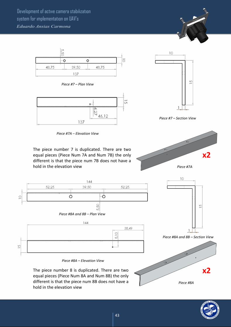
The piece number 7 is duplicated. There are two equal pieces (Piece Num 7A and Num 7B) the only different is that the piece num 7B does not have a hold in the elevation view
The piece number 8 is duplicated. There are two equal pieces (Piece Num 8A and Num 8B) the only different is that the piece num 8B does not have a hold in the elevation view
Piece #7 – Plan View
Piece #8A
Piece Num 7 - Plan View
Piece #7A – Elevation View
Piece #7 – Section View
Piece #7A
Piece #8A and 8B – Plan View
Piece #8A – Elevation View
Piece #8A and 8B – Section View
x2
x2

Development of active camera stabilization
system for implementation on UAV's
44
Piece #9
Piece #10
Piece #9 – Elevation View
Piece #9 – Plan View
Piece #9 – Section View
Piece #10 – Plan View
Piece #10 – Section View
Piece #10 – Elevation View
The pieces #9 and #10 are quadruplicate and the diameter of the hold where the bearings are accommodated could be change. The hold size depends of the bearing’s diameter.
x4
x4

Development of active camera stabilization
system for implementation on UAV's
45
Instructions:
STEP 1
STEP 2
Screw the piece # 1 to the piece # 5 by the three union points like it shown in the picture.
First of all, screw the piece # 6 to the piece # 1 by the four union points. Screw the servo to the
piece # 6 and place the servo arm.
1 5
6
1

Development of active camera stabilization
system for implementation on UAV's
46
Take the bearings and place them inside of
the holes are found in the pieces # 10.
Join with a rivet the pieces # 9 and # 10.
Repeat the step four times.
STEP 3
x4
STEP 4
Place with a screw like shows the picture,
the advice in the piece # 8A which will be
installed the springs for the movement
system.
This step must be repeated with the piece #
7A but in this case, the advice has to be
installed in the opposite side of the piece.
STEP 5
9 10
8A
8A
8B
9A
9B
2
Join the piece # 2 with the pieces # 7A, # 7B, # 8A and # 8B. Pay special attention to the
order of the pieces.

Development of active camera stabilization
system for implementation on UAV's
47
Join with screws the pieces created in the step 3, two of them have to be screw between
the pieces # 1 and # 2. The other two have to be screw between the pieces # 2 and # 3.
All the pieces have to be positioned in the same level.
STEP 6
3
STEP 5
STEP 1
STEP 3
STEP 3
STEP 3
STEP 3

Development of active camera stabilization
system for implementation on UAV's
48
Screw the piece # 4 to the piece # 3 as show the picture. Fix the servo to the piece # 4
with screws and finally place the servo arm.
First of all fix the bases for the shock absorbers with screws to the piece # 3. Do the same
procedure for the covers but now fix them to the UAV. Set the springs in the base and the
cover.
STEP 7
STEP 8
4
3
BASE
COVER
SPRING
3

Development of active camera stabilization
system for implementation on UAV's
49
Finally fix the camera introducing a screw between the device and the piece # 5. In this
case is necessary a special screw to introduce into the camera, it could be like a typical
fixation of a camera tripod.
Assemble the movement mechanism placing a spring to each side of the piece installed in
the step 4. Introduce the movement arm into the springs and the hole of the piece; fix
them with a cover and a screw.
STEP 9
STEP 10
STEP 4 ARM SPRING SPRING
COVER
CAMERA
5

Development of active camera stabilization
system for implementation on UAV's
50
5. Conclusions
This mechanism is very useful for unmanned
aerial vehicles. One of the principal reasons
is because it can be installed in a lot of the
UAV’s with similar characteristics in weight
and size.
It is fully adaptable, not only to different
aircrafts but also to different types of
cameras. The flexibility and simplicity of the
mechanism, allowed a quick modification of
its features in short time.
The pieces can be joined by welding or bolted to each other as has been done
along the project.
Because of lack of resources, it has not
been possible to test the operation of the
mechanism. Neither, it has been possible
check the pieces resistance through a
destructive or non destructive testing and
has not been possible to capture images to
test the proper functioning of the
stabilization system of the camera.
However, the theoretical calculations prove that the systems and mechanisms are
feasible. It is possible that during the construction of the mechanism, appear some
problems or inconveniences which we did not count on, but still, any problem can
be resolved with minor modifications.
Development of active camera stabilization
system for implementation on UAV's
51
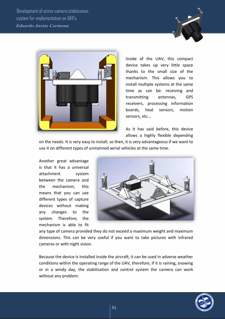
Inside of the UAV, this compact
device takes up very little space
thanks to the small size of the
mechanism. This allows you to
install multiple systems at the same
time as can be: receiving and
transmitting antennas, GPS
receivers, processing information
boards, heat sensors, motion
sensors, etc...
As it has said before, this device
allows a highly flexible depending
on the needs. It is very easy to install, so then, it is very advantageous if we want to
use it on different types of unmanned aerial vehicles at the same time.
Another great advantage
is that it has a universal
attachment system
between the camera and
the mechanism; this
means that you can use
different types of capture
devices without making
any changes to the
system. Therefore, the
mechanism is able to fit
any type of camera provided they do not exceed a maximum weight and maximum
dimensions. This can be very useful if you want to take pictures with infrared
cameras or with night vision.
Because the device is installed inside the aircraft, it can be used in adverse weather
conditions within the operating range of the UAV, therefore, If it is raining, snowing
or in a windy day, the stabilization and control system the camera can work
without any problem.

Development of active camera stabilization
system for implementation on UAV's
52
6. References
1- www.canon.es Web page of Canon Company
2- http://www.hobbyking.com Web page of Hobbyking Company
3- http://www.directindustry.com Web page of Direct Industry Company
4- http://blog.bricogeek.com/noticias/robotica/estabilizador-de-camara-con-giroscopio-de-3-ejes Blog published by Oscar Gonzalez on 29/05/2010
5- http://www.draganfly.com Web page of Draganfly innovations inc
6- http://diydrones.com Web page of Diydrones Company
7- http://lt.rsdelivers.com Web page of RS Components & Controls Company
8- http://www.superrobotica.com
Web page of Superrobotica Company
9- http://www.myresearch.lt Blog published by Aleksey Zaitsevsky
10- www.wikipedia.com