Development of a UAV system for VNIR-TIR acquisitions...
10
Development of a UAV system for VNIR-TIR acquisitions in precision agriculture Misopolinos L. a , Zalidis Ch. a , Liakopoulos V. a,b , Stavridou D. a , Katsigiannis P. a , Alexandridis T.K. c , Zalidis G. a,c a Interbalkan Environment Center, 18 Loutron Str. Lagadas, Greece; Tel.: +30 2394023485; E-mail: [email protected]; b Aeroview,30 Makedonias Str. Xanthi, Greece; Tel +306978116071; E-mail: [email protected]; c Aristotle University of Thessaloniki, Faculty of Agriculture, Thessaloniki, Greece; Tel +30 2310 991777; E-mail: [email protected] ABSTRACT Adoption of precision agriculture techniques requires the development of specialized tools that provide spatially distributed information. Both flying platforms and airborne sensors are being continuously evolved to cover the needs of plant and soil sensing at affordable costs. Due to restrictions in payload, flying platforms are usually limited to carry a single sensor on board. The aim of this work is to present the development of a vertical take-off and landing autonomous unmanned aerial vehicle (VTOL UAV) system for the simultaneous acquisition of high resolution vertical images at the visible, near infrared (VNIR) and thermal infrared (TIR) wavelengths. A system was developed that has the ability to trigger two cameras simultaneously with a fully automated process and no pilot intervention. A commercial unmanned hexacopter UAV platform was optimized to increase reliability, ease of operation and automation. The designed systems communication platform is based on a reduced instruction set computing (RISC) processor running Linux OS with custom developed drivers in an efficient way, while keeping the cost and weight to a minimum. Special software was also developed for the automated image capture, data processing and on board data and metadata storage. The system was tested over a kiwifruit field in northern Greece, at flying heights of 70 and 100m above the ground. The acquired images were mosaicked and geo-corrected. Images from both flying heights were of good quality and revealed unprecedented detail within the field. The normalized difference vegetation index (NDVI) was calculated along with the thermal image in order to provide information on the accurate location of stressors and other parameters related to the crop productivity. Compared to other available sources of data, this system can provide low cost, high resolution and easily repeatable information to cover the requirements of precision agriculture. Keywords: unmanned aerial vehicle, precision farming, robotic helicopter, visible-near infrared, thermal infrared 1. INTRODUCTION Precision agriculture (PA) is a farming management concept based on observing, measuring and responding to inter and intra-field variability in crops. Although commercially practiced only since the 1990s, it is considered as one of the top ten revolutions in agriculture 1 . PA practices require higher spatial and temporal resolution information on the crop-soil- water status of a given field than conventional agriculture. Thus, remote and proximal sensing techniques have been developed to account for these needs. Recent technological development in the field of remote sensors and unmanned aerial vehicles (UAV) has been proven to be a power tool for the purposes of PA, providing low cost tools that achieve highly accurate results with increased usability. A significant load of effort by several developers has been given during the last few years towards the optimization of UAV systems. Primicerio et al. 2 introduced a UAV as a flexible and powerful tool for site-specific vineyard management. It utilized a multispectral camera for vegetation canopy reflectance recording, in order to produce vigour maps that clearly showed crop heterogeneity conditions; in good agreement with ground-based observations. The need for further development was noted, in order to achieve longer flight duration and thus cover larger fields, to eliminate the camera vibration for higher image clarity, and to achieve platform autonomous take-off and land. Another important issue was the miniaturization of the camera sensors that would potentially increase flight time and usage of multiple sensors. In order to develop low-cost agricultural remote sensing system based on an autonomous unmanned aerial vehicle (UAV) Xiang
Transcript of Development of a UAV system for VNIR-TIR acquisitions...
Development of a UAV system for VNIR-TIR acquisitions in precision
agriculture
Misopolinos L.a, Zalidis Ch.
a, Liakopoulos V.
a,b, Stavridou D.
a, Katsigiannis P.
a, Alexandridis T.K.
c,
Zalidis G.a,c
a Interbalkan Environment Center, 18 Loutron Str. Lagadas, Greece; Tel.: +30 2394023485; E-mail:
[email protected]; b Aeroview,30 Makedonias Str. Xanthi, Greece; Tel +306978116071; E-mail:
[email protected]; c Aristotle University of Thessaloniki, Faculty of Agriculture, Thessaloniki,
Greece; Tel +30 2310 991777; E-mail: [email protected]
ABSTRACT
Adoption of precision agriculture techniques requires the development of specialized tools that provide spatially
distributed information. Both flying platforms and airborne sensors are being continuously evolved to cover the needs of
plant and soil sensing at affordable costs. Due to restrictions in payload, flying platforms are usually limited to carry a
single sensor on board. The aim of this work is to present the development of a vertical take-off and landing autonomous
unmanned aerial vehicle (VTOL UAV) system for the simultaneous acquisition of high resolution vertical images at the
visible, near infrared (VNIR) and thermal infrared (TIR) wavelengths. A system was developed that has the ability to
trigger two cameras simultaneously with a fully automated process and no pilot intervention. A commercial unmanned
hexacopter UAV platform was optimized to increase reliability, ease of operation and automation. The designed systems
communication platform is based on a reduced instruction set computing (RISC) processor running Linux OS with
custom developed drivers in an efficient way, while keeping the cost and weight to a minimum. Special software was
also developed for the automated image capture, data processing and on board data and metadata storage.
The system was tested over a kiwifruit field in northern Greece, at flying heights of 70 and 100m above the ground. The
acquired images were mosaicked and geo-corrected. Images from both flying heights were of good quality and revealed
unprecedented detail within the field. The normalized difference vegetation index (NDVI) was calculated along with the
thermal image in order to provide information on the accurate location of stressors and other parameters related to the
crop productivity. Compared to other available sources of data, this system can provide low cost, high resolution and
easily repeatable information to cover the requirements of precision agriculture.
Keywords: unmanned aerial vehicle, precision farming, robotic helicopter, visible-near infrared, thermal infrared
1. INTRODUCTION
Precision agriculture (PA) is a farming management concept based on observing, measuring and responding to inter and
intra-field variability in crops. Although commercially practiced only since the 1990s, it is considered as one of the top
ten revolutions in agriculture 1. PA practices require higher spatial and temporal resolution information on the crop-soil-
water status of a given field than conventional agriculture. Thus, remote and proximal sensing techniques have been
developed to account for these needs. Recent technological development in the field of remote sensors and unmanned
aerial vehicles (UAV) has been proven to be a power tool for the purposes of PA, providing low cost tools that achieve
highly accurate results with increased usability. A significant load of effort by several developers has been given during
the last few years towards the optimization of UAV systems.
Primicerio et al. 2 introduced a UAV as a flexible and powerful tool for site-specific vineyard management. It utilized a
multispectral camera for vegetation canopy reflectance recording, in order to produce vigour maps that clearly showed
crop heterogeneity conditions; in good agreement with ground-based observations. The need for further development
was noted, in order to achieve longer flight duration and thus cover larger fields, to eliminate the camera vibration for
higher image clarity, and to achieve platform autonomous take-off and land. Another important issue was the
miniaturization of the camera sensors that would potentially increase flight time and usage of multiple sensors. In order
to develop low-cost agricultural remote sensing system based on an autonomous unmanned aerial vehicle (UAV) Xiang

and Tian 3 introduced a helicopter platform equipped with only a multispectral camera and autonomous pilot system to
monitor turf grass herbicide applications. The system was based on an easily transportable helicopter platform and the
whole autopilot system was custom developed by the team, thus requiring a high level of specialization. Another issue
noted was the difficulty to operate and maintain this system powered by an internal combustion engine, as well as the
higher cost than the equivalent electric motor systems. Nebikera et al. 4 presented a prototype light-weight multispectral
sensor for micro UAV used in for assessing crop health. Turner et al. 5 developed a UAV capable of collecting very high
resolution visible, multispectral and thermal imagery for precision viticulture. They produced Digital Surface Models
(DSMs) of the vineyards, soil moisture map for assessment of irrigation efficiency, and vegetation indices for assessment
of vines vigour and health. It is pointed out that they used the two sensors (multispectral and thermal) individually due to
multicopter payload limitation.
In order to summarize, the main problems identified in literature are the flying duration limit, payload restriction, image
distortion due to wide angle viewing, photogrammetric distortions due to low overlap, image blurring due to high flying
speed, image differences due to changing illumination conditions in the same flight. Thus, there is space for further
improvement of such systems, taking into consideration the above mentioned problems. The aim of this work is to
present the development of a hexacopter UAV platform for autonomous, simultaneous triggering of two cameras,
covering the target field in as few flights as possible, in a speed acceptable by the sensors on board.
2. MATERIALS AND METHODS
2.1 Hexacopter UAV platform
The hexacopter UAV platform (Figure 1) that was used to accommodate the necessary equipment is a hexacopter UAV
platform, which was an assembly of different parts. The main frame was the Vulcan Hexa and the technical
specifications are presented in Table 1. The flight controller installed was the WooKong-M, a complete flight control
system for all commercial, industrial and professional multi-rotor platforms. It gives the user the option of the following
functions: (i) pre-program a flight including up to 50 waypoints with custom parameters for speed, altitude, type of turn
between waypoints, and even custom robotic servo actions to be completed at each waypoint, (ii) automatic take off,
complete the entire mission, return home, and land itself at the location it took off, (iii) several fail-safe measures to
account for human errors like excessive flight duration or an altitude below ground level, and (iv) flexibility to change
the flight parameters on the fly, during the actual flight. This flight controller was equipped with a ground station, a
graphical user interface for the PC, in order to control through telemetry all the flight parameters.
Table 1. Vulcan Hexa multicopter technical specifications.
Technical information Vulcan Hexacopter UAV platfrom
Type Multicopter
Diameter 800mm
Weight 5kg
Payload capability 4 Kg
Voltage 22V
Battery capacity 16.000 mah
Flying time 15min
Maximum operation altitude (water level) 2500m
Waypoints 50
Fail safe function Return to home and land
Auto take off yes
Maximum speed 10m/sec
Maximum ascent 5m/sec
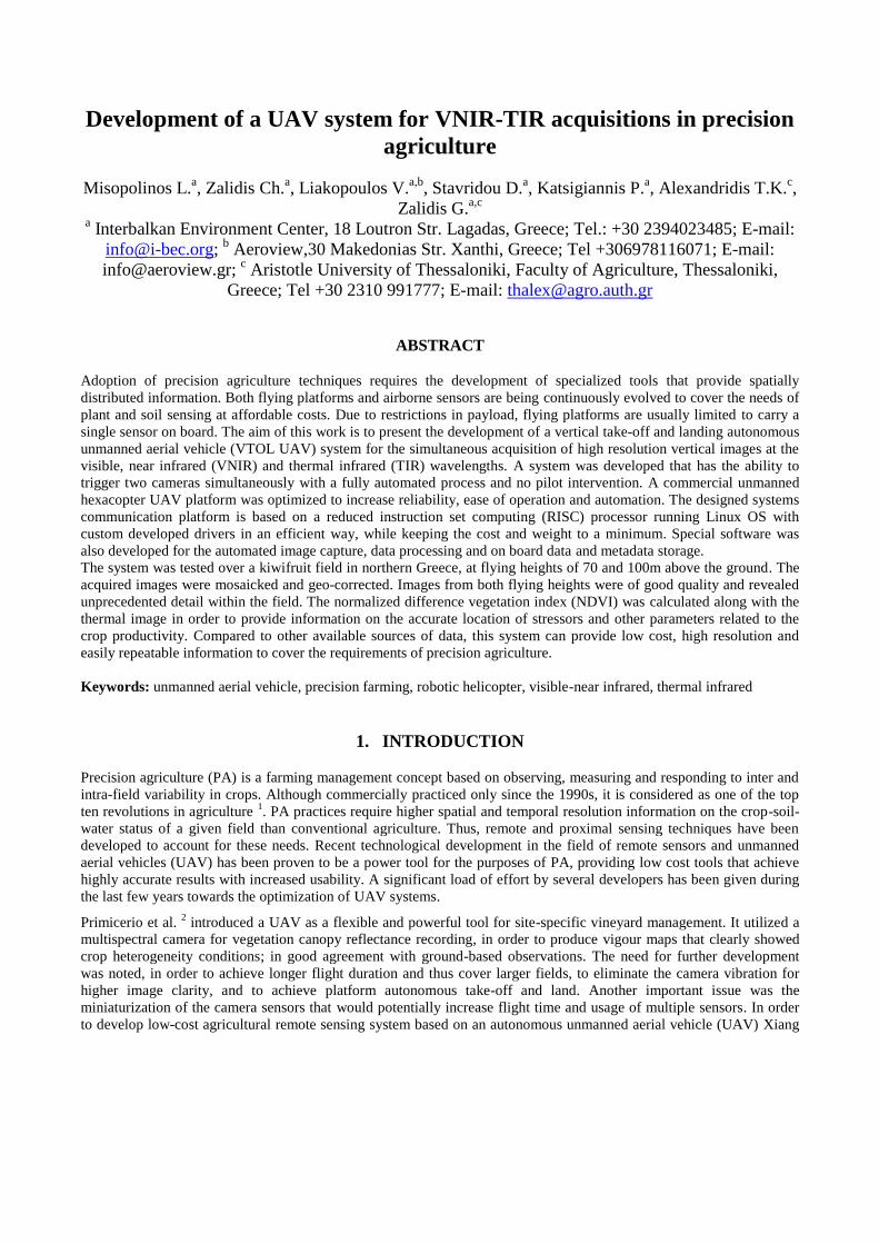
Figure 1. Hexacopter UAV platform with attached thermal and multispectral camera sensors.
2.2 Cameras on board and stabilization mechanism
Two cameras were carried on board. The multispectral imaging camera is the Lightweight Agricultural Digital Camera
ADC-Lite (Tetracam, Inc.), specially designed for operation aboard unmanned aerial vehicles and optimized for
monitoring vegetation canopy reflectance. Its spectral bands are green (0.53-0.61 μm), red (0.63-0.69 μm) and near
infrared (0.78-0.90 μm), and are approximately identical to bands 2, 3 and 4 of the Landsat TM sensor, respectively.
Thermal images were acquired using the A65 thermal imaging camera (FLIR Systems, Inc.). This model addresses the
combined demand on high image quality and light device weight for agricultural remote sensing operations with the
hexacopter UAV platform. The sensor spectral range is 7.5–13 µm, with an IFOV (Instantaneous Field of View) of 1.31
mRad (milliradians) which corresponds to a spatial resolution of around 6.55 cm when capturing from a 50-meter
altitude. The combined weight of the two sensors does not exceed 0.5 kg, making them ideal for the hexacopter UAV
platform developed.
In order to ensure that the cameras would acquire vertical images under all flight circumstances, a gimbal was installed
between the landing skids of the hexacopter UAV platform (Maytech MTGBM3F5D-B brushless gimbal 3 Axis). The
gimbal was mounted on with specially design dumpers in order to eliminate vibration transfer from the hexacopter UAV
platform to the cameras that would have resulted to low quality image acquisition.
Data link
GPS Receiver
Battery packBattery pack
Gimbal
Dumpers
Thermal camera
Multi spectral
camera
Custom made base
Silicone tube
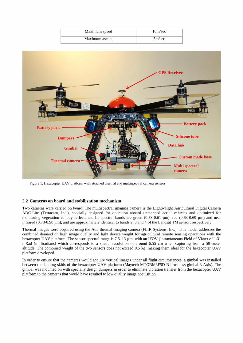
2.3 Hexacopter UAV platform flight debugging
A problem that has been identified from the test flights was the electrical noise interference between the GPS receiver
and the speed controllers. This was due to the initial configuration of the system and the short distance of the two
components, which created a magnetic field that did not allow smooth operation. Thus, the appropriate distance was
achieved by placing the GPS receiver on a pole that elevated the GPS 12 cm above the system.
Figure 2. Final position with the extension pole
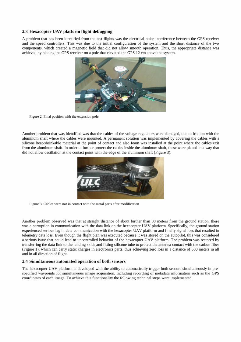
Another problem that was identified was that the cables of the voltage regulators were damaged, due to friction with the
aluminum shaft where the cables were mounted. A permanent solution was implemented by covering the cables with a
silicone heat-shrinkable material at the point of contact and also foam was installed at the point where the cables exit
from the aluminum shaft. In order to further protect the cables inside the aluminum shaft, these were placed in a way that
did not allow oscillation at the contact point with the edge of the aluminum shaft (Figure 3).
Figure 3. Cables were not in contact with the metal parts after modification
Another problem observed was that at straight distance of about further than 80 meters from the ground station, there
was a corruption in communication with the data link on the hexacopter UAV platform. Specifically, the ground station
experienced serious lag in data communication with the hexacopter UAV platform and finally signal loss that resulted in
telemetry data loss. Even though the flight plan was executed because it was stored on the autopilot, this was considered
a serious issue that could lead to uncontrolled behavior of the hexacopter UAV platform. The problem was restored by
transferring the data link to the landing skids and fitting silicone tube to protect the antenna contact with the carbon fiber
(Figure 1), which can carry static charges in electronics parts, thus achieving zero loss in a distance of 500 meters in all
and in all direction of flight.
2.4 Simultaneous automated operation of both sensors
The hexacopter UAV platform is developed with the ability to automatically trigger both sensors simultaneously in pre-
specified waypoints for simultaneous image acquisition, including recording of metadata information such as the GPS
coordinates of each image. To achieve this functionality the following technical steps were implemented.

The images from the sensors are stored with the following additional information: geographical location (Latitude,
Longitude and altitude) and the exact time of acquisistion, information received from the GPS. ADC-Lite has its own
triggering process that stores images automatically in the camera's internal storage memory. The triggering process was
implemented by a triggering signal which was send from the hexacopter UAV platform’s autopilot system (Figure 4).
Also ADC-Lite was equipped with a system to store the coordinates from an external GPS receiver (Figure 4).
While the ADC-Lite sensor was equipped with integrated storage, GPS data input and external triggering system, the
FLIR A65 sensor did not include any of the above and a need for an external microprocessor was apparent, in order to
interface with the sensor and be controlled on the hexacopter UAV platform automatically. To satisfy that need, a
Raspberry Pi model B (Figure 4) was chosen because of its very small size, low power consumption and low cost, which
is a necessity for cost effective airborne systems. The Raspberry Pi was connected via ethernet with the FLIR A65 sensor
and saved the images on its internal storage upon external trigger. In order for the RaspberryPi to store the exact
geographical location of the image taken, the GPS, used also for the ADC-Lite, was connected via USB port. The trigger
process for taking images, similar to the ADC-Lite, was signaled from the autopilot.
The Rasberry Pi microprocessor installed on the hexacopter UAV platform run a Debian distribution of Linux OS.
Certain modifications were implemented and new software was developed for the system. In order to interface with the
camera sensor, as described above, an open source implementation of the GigE Vision/GenICam protocol 6 was used, the
aravis 7.
Figure 4. Connectivity diagram of individual components.
In order for the Raspberry Pi microprocessor to be able to communicate with the GPS module and capture coordinates,
gpsd 8 was used as a daemon to constantly collect GPS data. Then, a custom linux daemon was developed in Python
9
that was waiting for a trigger signal on one of the microprocessor’s digital input pins. After the trigger reached the
microprocessor, the daemon used an implementation of aravis library, written in Python for simplicity 10
, in order to
interface with the FLIR A65 sensor over ethernet and request the capture of a single frame. That frame was then saved to
the microprocessor’s internal memory, alongside with the corresponding metadata and an output image is produced.
Output images could be downloaded later, when the hexacopter UAV platform was on the ground, simply by connecting
a laptop to the microprocessor over ethernet.
Output images were stored either as 8-bit monochrome jpeg files or as 14-bit monochrome tiff files on the raspberry. In
both options metadata were included in the files (using the Exif format), such as GPS coordinates, time of shooting, etc.
In the latter case, of 14-bit depth images, it allowed the extraction of the exact temperature per pixel using a formula
given by the manufacturer (FLIR A65) in order to transform radiometric signal values to temperature readings.
Finally the Wookong’s autopilot ability was used to send a trigger signal on certain events through a PWM (Pulse Width
Modulation) relay switch (Figure 4) in order to trigger both sensors simultaneously and achieve electrical isolation
between the two circuits. It is worth to mention, that it is possible to program the Wookong autopilot to send a trigger
signal automatically (e.g. when the hexacopter UAV platform reaches a pre-programmed waypoint), as well as manually,
upon user input. All the above described systems are powered from a 12V lithium polymer battery that is able to power
the system much longer than the flight time.
3. OPERATION OF THE HEXACOPTER UAV PLATFORM FOR PRECISION
AGRICULTURE
The system was tested over a kiwifruit orchard in Chrysoupoli (Kavala, Greece). The field size was 23.420 m2 on flat
terrain, and contained a plantation of kiwifruit (Actinidia deliciosa var. Hayward). The plants were 19 years old, own-
rooted, with trunk height at 1.85m. The training system was a Pergola, with plantation density from 620-640 plants/ha.
Several deployments of the system were tested over the kiwi field in a day with changing overcast (7 November 2014),
acquiring nadir images at flying height of 70 and 100m above the ground. The overlap was set to 60% and the sidelap to
40% for all flights.
In order to cover the kiwi field at 70m flying height, 103 images were acquired during two flights of 14.5 minutes each.
The same field was covered at 100m flying height with 54 images with a single flight of 14.5 minutes. The images of
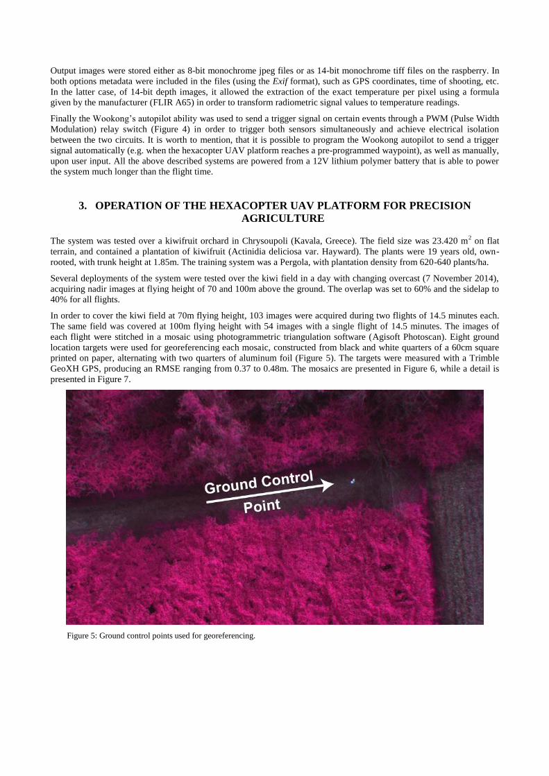
each flight were stitched in a mosaic using photogrammetric triangulation software (Agisoft Photoscan). Eight ground
location targets were used for georeferencing each mosaic, constructed from black and white quarters of a 60cm square
printed on paper, alternating with two quarters of aluminum foil (Figure 5). The targets were measured with a Trimble
GeoXH GPS, producing an RMSE ranging from 0.37 to 0.48m. The mosaics are presented in Figure 6, while a detail is
presented in Figure 7.
Figure 5: Ground control points used for georeferencing.
a. b.
c. d.
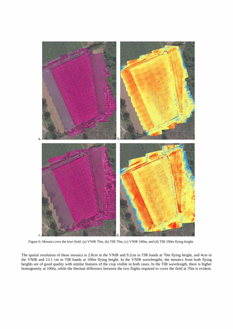
Figure 6: Mosaics over the kiwi field: (a) VNIR 70m, (b) TIR 70m, (c) VNIR 100m, and (d) TIR 100m flying height.
The spatial resolution of these mosaics is 2.8cm in the VNIR and 9.2cm in TIR bands at 70m flying height, and 4cm in
the VNIR and 13.1 cm in TIR bands at 100m flying height. In the VNIR wavelengths, the mosaics from both flying
heights are of good quality with similar features of the crop visible in both cases. In the TIR wavelength, there is higher
homogeneity at 100m, while the thermal difference between the two flights required to cover the field at 70m is evident.
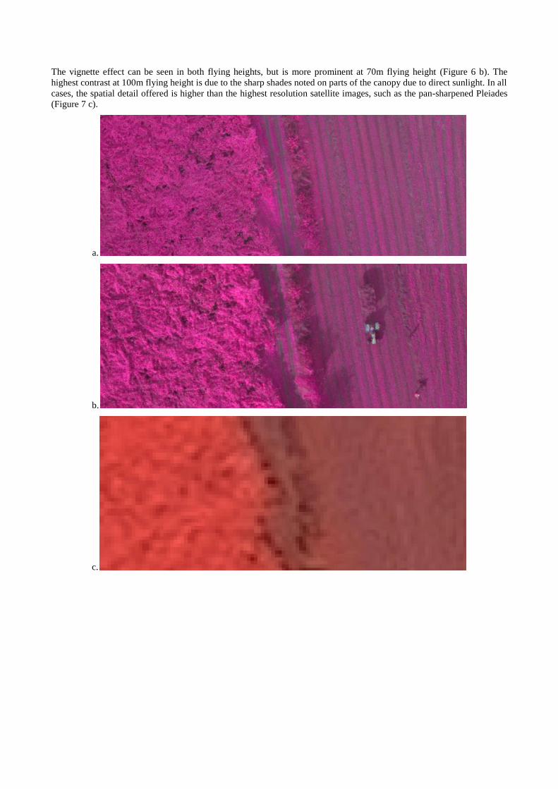
The vignette effect can be seen in both flying heights, but is more prominent at 70m flying height (Figure 6 b). The
highest contrast at 100m flying height is due to the sharp shades noted on parts of the canopy due to direct sunlight. In all
cases, the spatial detail offered is higher than the highest resolution satellite images, such as the pan-sharpened Pleiades
(Figure 7 c).
a.
b.
c.
d.
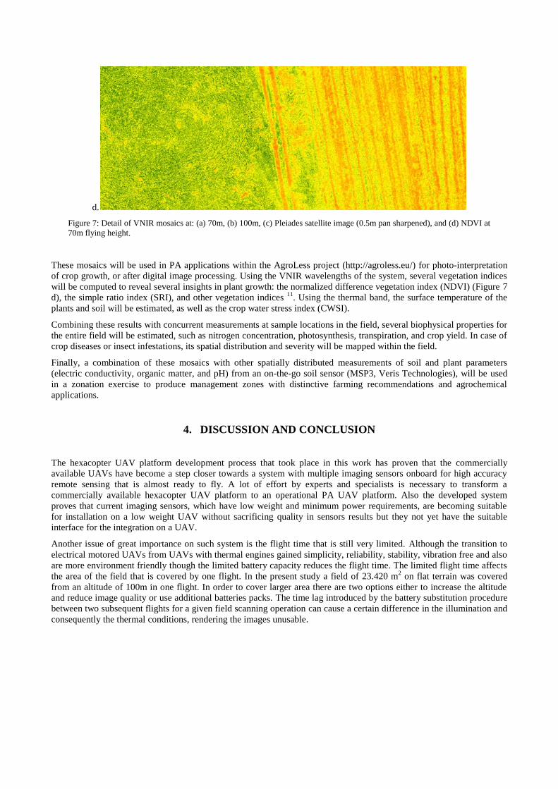
Figure 7: Detail of VNIR mosaics at: (a) 70m, (b) 100m, (c) Pleiades satellite image (0.5m pan sharpened), and (d) NDVI at
70m flying height.
These mosaics will be used in PA applications within the AgroLess project (http://agroless.eu/) for photo-interpretation
of crop growth, or after digital image processing. Using the VNIR wavelengths of the system, several vegetation indices
will be computed to reveal several insights in plant growth: the normalized difference vegetation index (NDVI) (Figure 7
d), the simple ratio index (SRI), and other vegetation indices 11
. Using the thermal band, the surface temperature of the
plants and soil will be estimated, as well as the crop water stress index (CWSI).
Combining these results with concurrent measurements at sample locations in the field, several biophysical properties for
the entire field will be estimated, such as nitrogen concentration, photosynthesis, transpiration, and crop yield. In case of
crop diseases or insect infestations, its spatial distribution and severity will be mapped within the field.
Finally, a combination of these mosaics with other spatially distributed measurements of soil and plant parameters
(electric conductivity, organic matter, and pH) from an on-the-go soil sensor (MSP3, Veris Technologies), will be used
in a zonation exercise to produce management zones with distinctive farming recommendations and agrochemical
applications.
4. DISCUSSION AND CONCLUSION
The hexacopter UAV platform development process that took place in this work has proven that the commercially
available UAVs have become a step closer towards a system with multiple imaging sensors onboard for high accuracy
remote sensing that is almost ready to fly. A lot of effort by experts and specialists is necessary to transform a
commercially available hexacopter UAV platform to an operational PA UAV platform. Also the developed system
proves that current imaging sensors, which have low weight and minimum power requirements, are becoming suitable
for installation on a low weight UAV without sacrificing quality in sensors results but they not yet have the suitable
interface for the integration on a UAV.
Another issue of great importance on such system is the flight time that is still very limited. Although the transition to
electrical motored UAVs from UAVs with thermal engines gained simplicity, reliability, stability, vibration free and also
are more environment friendly though the limited battery capacity reduces the flight time. The limited flight time affects
the area of the field that is covered by one flight. In the present study a field of 23.420 m2 on flat terrain was covered
from an altitude of 100m in one flight. In order to cover larger area there are two options either to increase the altitude
and reduce image quality or use additional batteries packs. The time lag introduced by the battery substitution procedure
between two subsequent flights for a given field scanning operation can cause a certain difference in the illumination and
consequently the thermal conditions, rendering the images unusable.

The use of a VTOL hexacopter UAV platform was essential to acquire sharp thermal images, which require low flying
speeds when bolometric thermal cameras are used 12
. The gimbal was proven important for ensuring vertical images
while the UAV is moving, especially against the wind.
The present study has proven the necessity of the development of the hexacopter UAV platform by achieving
simultaneous acquisition of good quality VNIR and TIR images. These can be utilized for monitoring of crop growth
conditions and assessment of water, nutrient and other stresses in PA applications, where high spatial and temporal
resolutions are essential.
ACKNOWLEDGEMENTS
This project “Joint reference strategies for rural activities of reduced inputs” with acronym AGRO_LESS is co-founded by the
European Union (ERDF) and National Funds of Greece and Bulgaria under the European Territorial Cooperation Programme,
Greece–Bulgaria 2007-2013
REFERENCES
[1] Crookston K., “A top 10 list of developments and issues impacting crop management and ecology during the
past 50 years,” Crop Science 46, 2253–2262 (2006).
[2] Primicerio J., Filippo D. G. S., Fiorillo E., Genesio L., Lugato E., Matese A., Vaccari F. P., “A flexible
unmanned aerial vehicle for precision agriculture,” Springer Science + Business Media Precision Agriculture
13(4), 517–523 (2012).
[3] Xiang H., Tian L., “Development of a low-cost agricultural remote sensing system based on an autonomous
unmanned aerial vehicle (UAV),” Elsevier Biosystems Engineering 108(2), 174-190 (2011).
[4] Nebikera S., Annena A., Scherrerb M., Oeschc D., “A light-weight multispectral sensor for micro uav –
opportunities for very high resolution airborne remote sensing,” The International Archives of the
Photogrammetry Remote Sensing and Spatial Information Sciences 37(B1), 1193-1199 (2008).
[5] Turner D., Lucieer A., Watsona C.,“Development of an Unmanned Aerial Vehicle (UAV) for hyper resolution
vineyard mapping based on visible, multispectral, and thermal imagery,” Proceedings of the 34th International
Symposium on Remote Sensing of Environment Sydney Australia, 4-7 (2011)
[6] Leutron vision, “GigE Vision and GenICam Standards,” www.leutron.com/media/articles-and-
whitepapers/gigevision-genicam-standard/
[7] Aravis, “A vision library for genicam based cameras,” wiki.gnome.org/Aravis (4 December 2013)
[8] Open source code, “Service daemon that monitors one or more GPSes or AIS receivers attached to a host
computer through serial or USB ports,” http://www.catb.org/gpsd/ [9] Zalidis Ch, “Scripts running on Raspberry Pi, used on an UAV hexacopter,” https://github.com/czalidis/uav-
scripts
[10] Zalidis Ch, “Python interface to aravis, “ https://github.com/oroulet/python-aravis
[11] Silleos N. G., Alexandridis T. K., Gitas I. Z., Perakis K., “Vegetation Indices: advances made in biomass
estimation and vegetation monitoring in the Last 30 Years,” Geocarto International, 21(4), 21-28 (2006).
[12] Meron M., Tsipris J., Orlov V., Alchanatis V., Cohen Y., “Crop water stress mapping for site-specific irrigation
by thermal imagery and artificial reference surfaces,” Precision agriculture, 11(2), 148-162 (2010)