
Development of a Regenerative Pump Impeller Using Rapid ...
8
Abstract This paper presents a method of rapid manufacture used in the development of a regenerative pump impeller. Rapid manufacturing technology was used to create complex impeller blade proiles for testing as part of a regenerative pump optimisation process. Regenerative pumps are the subject of increased interest in industry. Ten modiied impeller blade proiles, relative to the standard radial coniguration, were evaluated with the use of computational luid dynamics and experimental testing. Prototype impellers were needed for experimental validation of the CFD results. The manufacture of the complex blade proiles using conventional milling techniques is a considerable challenge for skilled machinists. The complexity of the modiied blade proiles would normally necessitate the use of expensive CNC machining with 5 axis capability. With an impeller less than 75 mm in diameter and a maximum blade thickness of 1.3mm, a rapid manufacturing technique enabled production of complex blade proiles that were dimensionally accurate and structurally robust enough for testing. As more advanced rapid prototyping machines become available in the study in the future, e.g. 3D photopolymer jetting machine, the quality of the parts particularly in terms of surface inish will improve and the amount of post processing operations will reduce. This technique offers the possibility to produce components of increased complexity whilst ensuring quality, strength, performance and speed of manufacture. The ability to manufacture complex blade proiles that are robust enough for testing, in a rapid and cost effective manner is proving essential in the overall design optimisation process for the pump. Keywords: rapid manufacturing, rapid prototyping, rapid tooling, NOMENCLATURE A Cross sectional area (m²) ABS Acrylonitrile-Butadiene-Styrene CO 2 Carbon Dioxide CFD Computational Fluid Dynamics CNC Computer Numerically Controlled D Impeller diameter (m) FDM Fused Deposition Modelling HPC High Performance Computer MTON Metric Ton P Power (kW) Q Volume Flowrate (m³/s) RM Rapid Manufacturing RP Rapid Prototyphing RT Rapid Tooling TWh Terawatt Hour η Eficiency φ Flow coeficient ω Rotational speed (Rev/min) INTRODUCTION Pumps are the single largest user of electricity in industry in the European Union and energy savings of 3% would result in a 1.1TWH p.a. reduction in consumption or a saving of 0.54 Mton of 2 CO production [1]. As industry attempts to make energy savings and reduce environmental impact, this paper considers the manufacture of impellers to compare the computational predictions with experimental results of a regenerative pump with a view to improving pump performance. The complex low-ield within a regenerative pump represents a signiicant challenge to detailed mathematical modelling as there is considerable low separation in the impeller blading [2, 3, 4]. Analytical models do not describe the low characteristics fully as they are based on simpliied assumptions and experimental correction factors [5, 6, 7]. The previous theories rely on assumptions not based on detailed measurements or rigorous CFD calculations. The main characteristic of such pumps is the ability to generate high discharge pressures at low lowrates. Although the pump has other advantages the main limitation is its inherent lack of hydraulic eficiency, typically 35-50%. The aim of the project was to use CFD to optimise the blade proiles to increase the eficiency of the pump and CFD is a robust methos to obtain data Notwithstanding CFD being recognised as a good design tool in the initial design stage, the computational results must be validated with experimental data. It is therefore critical to have access to manufacturing methods that can produce dimensionally accurate, small and complex impellers that are robust enough for testing. Prototypes this complex would normally be machined using computer numerical control (CNC) machining techniques. ig. 1: Regenerative Pump Impeller ig. 2: Chevron Proile Regenerative Pump Impeller Development of a Regenerative Pump Impeller Using Rapid Manufacturing Techniques 3 Q D ω (C 8 H 8 C 4 H 6 C 3 H 3 N) n Francis Quail, Thomas Scanlon, Matthew Stickland [email protected] [email protected] [email protected] Department of Mechanical Engineering, Strathclyde University, JamesWeir Building, 75 Montrose Street, Glasgow, G1 1XJ, United Kingdom
Transcript of Development of a Regenerative Pump Impeller Using Rapid ...

Abstract – This paper presents a method of rapid manufacture
used in the development of a regenerative pump impeller.
Rapid manufacturing technology was used to create complex
impeller blade proiles for testing as part of a regenerative pump optimisation process. Regenerative pumps are the subject of
increased interest in industry. Ten modiied impeller blade proiles, relative to the standard radial coniguration, were evaluated with the use of computational luid dynamics and experimental testing. Prototype impellers were needed for experimental validation of
the CFD results. The manufacture of the complex blade proiles using conventional milling techniques is a considerable challenge
for skilled machinists. The complexity of the modiied blade proiles would normally necessitate the use of expensive CNC machining
with 5 axis capability. With an impeller less than 75 mm in diameter
and a maximum blade thickness of 1.3mm, a rapid manufacturing technique enabled production of complex blade proiles that were dimensionally accurate and structurally robust enough for testing.
As more advanced rapid prototyping machines become available
in the study in the future, e.g. 3D photopolymer jetting machine, the quality of the parts particularly in terms of surface inish will improve and the amount of post processing operations will reduce.
This technique offers the possibility to produce components of
increased complexity whilst ensuring quality, strength, performance and speed of manufacture. The ability to manufacture complex
blade proiles that are robust enough for testing, in a rapid and cost effective manner is proving essential in the overall design
optimisation process for the pump.
Keywords: rapid manufacturing, rapid prototyping, rapid tooling,
NOMENCLATURE
A Crosssectionalarea (m²)
ABS Acrylonitrile-Butadiene-Styrene
CO2 CarbonDioxide
CFD ComputationalFluidDynamics
CNC ComputerNumericallyControlled
D Impellerdiameter (m)
FDM FusedDepositionModelling
HPC HighPerformanceComputer
MTON MetricTon
P Power (kW)
Q VolumeFlowrate (m³/s)
RM RapidManufacturing
RP RapidPrototyphing
RT RapidTooling
TWh TerawattHour
η Eficiency
φ Flowcoeficient
ω Rotationalspeed (Rev/min)
INTRODUCTION
Pumpsarethesinglelargestuserofelectricityinindustryin
theEuropeanUnionandenergysavingsof3%wouldresultina
1.1TWHp.a.reductioninconsumptionorasavingof0.54Mton
of2CO production [1].As industry attempts to make energy
savingsandreduceenvironmental impact, thispaperconsiders
the manufacture of impellers to compare the computational
predictionswithexperimentalresultsofaregenerativepumpwith
aviewtoimprovingpumpperformance.Thecomplexlow-ieldwithinaregenerativepumprepresentsasigniicantchallengetodetailed mathematical modelling as there is considerable lowseparation in the impeller blading [2, 3, 4].Analytical models
donotdescribe thelowcharacteristics fullyas theyarebasedon simpliied assumptions and experimental correction factors[5,6,7].Theprevious theories relyonassumptionsnotbased
on detailed measurements or rigorous CFD calculations. The
maincharacteristicofsuchpumpsistheabilitytogeneratehigh
dischargepressuresatlowlowrates.Althoughthepumphasotheradvantagesthemainlimitationis its inherentlackofhydraulic
eficiency,typically35-50%.TheaimoftheprojectwastouseCFDtooptimisethebladeproilestoincreasetheeficiencyofthepumpandCFDisarobustmethostoobtaindata
NotwithstandingCFDbeingrecognisedasagooddesigntool
in the initial design stage, the computational results must be
validatedwithexperimentaldata.Itisthereforecriticaltohave
accesstomanufacturingmethodsthatcanproducedimensionally
accurate,smallandcompleximpellersthatarerobustenoughfor
testing. Prototypes this complex would normally be machined
usingcomputernumericalcontrol(CNC)machiningtechniques.
ig.1: Regenerative Pump Impeller
ig.2: Chevron Proile Regenerative Pump Impeller
Development of a Regenerative Pump Impeller
Using Rapid Manufacturing Techniques
3
Q
Dφ
ω=
(C8H
8•
C
4H
6•C
3H
3N)
n
FrancisQuail,ThomasScanlon,MatthewStickland
[email protected]@[email protected]
DepartmentofMechanicalEngineering,StrathclydeUniversity,JamesWeirBuilding,75MontroseStreet,Glasgow,G11XJ,
UnitedKingdom

Having produced the standard radial impeller using
conventional milling techniques, ig. 1, to modify the bladeproiles presents a considerable challenge even for the mostskilledoperators.Thecomplexityofthemodiiedbladeproiles,showninig.2,wouldnormallynecessitatetheuseofexpensiveCNCmachineswith5-axiscapability.Thispaperinvestigatesan
accurate alternativemanufacturing technique to create suitable
impeller prototypes rapidly and cost effectively for use in
experimentsduringtheCFDevaluationprocess.Thechallenge
ofthisprojectwasnotonlytodevelopaCFDmodeltorepresentthe complex luid motion within the pump but also a robustmanufacturingprocesstoproducethecomplexoptimisedblade
designsneededforvalidationtesting.
InthisworktheresultsoftheCFDmodellingarecompared
toexperimentaldatacarriedoutbytheauthors.Whencorrectly
applied CFD, allows the user to study the low patterns in aregenerative pump and verify this with empirical test data.
The key technologies of rapid manufacturing (RM) are rapid
prototyping(RP)andrapidtooling(RT).RPisatechnologyfor
quick fabrication of physical models or functional prototypes
directly fromcomputer aideddesign (CAD)data.RT involves
theproductionofmouldsandtoolinginsertsusingRP.
EXPERIMENTALPROCEDURE
The experimental rig was a closed loop arrangement where
ahead tankcontains theworkingluidwhich in this casewaswater.The pump itself was driven by a 3kW induction motor
to operate at a constant speed of 3000 rpm. The motor was
connectedtoadynamometercontainingaloadcelltoaccurately
measure the input torque to the impeller for calculating the
pump eficiency.Theluidlowratewas determined by alowcontrolvalvemeteringthelowtoadegreenecessarytoproducearunningcharacteristic.Thisallowedarangeofpossiblelowstobemeasuredusingahalleffectturbinelowmeterataconstantrunningspeed(ig.3).Thetestprocedurewastomeasureinputpower,suctionpressure
and discharge pressure over a range of lowrates. The testimpellerwasa30bladedimpellerofwidth1.3mmanddiameter
74.5mm.Theimpellerwasadoublesuctionshapedesignedwith
alignmentof theblades tobalance axial thrust (ig. 4). In thisdesigntheimpellerhadradialteethorvanesmachinedintoeach
sideatitsperiphery.
Theluidenteredbothsidesoftheimpellerthroughasuctionportmakingtheunitadoublesuctionunit.Thecasinghadabarrier
wall “stripper” through which the impeller passes with close
clearance (ig. 4).The stripper seperateslowbetween suctionanddischargeandthelengthofthisbarrierwasequaltoatleast
twobladepitches.Theanglebetweentheinletandoutletports,
knownas the“stripperangle”,was30° in the testcase.When
thestripperangleissmall,moreworkisdoneontheluidduetotheincreasedpumpingregion,buttheleakagelowthroughthestrippergapfromtheoutlettoinletisincreased.
ig.3: Regenerative Pump Rig Schematic
DESIGNOFTHEREGENERATIVEPUMPIMPELLER
The regenerative pump uses an impeller with Turbine-type
bladesmountedontheperipheryrunninginanannularchannel
surroundingtheperipheryofthewheel.Inthedesign,theimpeller
hasradialteethmachinedintotheimpellerperipheryandtheluidpassesthroughanopenannularchannelandcirculatesrepeatedly
throughtheimpellervanes.(igs.1,4)
ig.4: Regenerative Pump
INLET
STRIPPER
OUTLET

The regenerative pump is sometimes also referred to as
a peripheral pump, turbulence pump, friction pump, turbine
pump,dragpump,sidechannelpump,tractionpumporvortex
pump.Therepeatedluidcirculationduringthelowprocessor‘multistaging’principallyallowsregenerativepumpstogenerate
highheadsatrelativelylowspeciicspeeds.Inspiteofhavingoperatingcharacteristicsthatmimicapositive
displacementpump,(powerdirectlyproportional tohead,with
maximumpowerrequiredatshutoff,andasteephead-capacity
curve),theregenerativepumpisakineticpump.Thatiskinetic
energyisimpartedtotheluidbytheseriesofimpulsesgiventotheluidbytherotatingimpellerblades.Theregenerativepumpwilldevelopsigniicantlyhigherheadsthanacentrifugalpumpwiththesamesizeimpeller.[8,10,11]
It is essential tohaveaccess tomanufacturingmethods that
can produce dimensionally accurate, small and complex parts.
Having determined that the baseline radial impeller (ig. 1),withparallelbladesurfaces,wasthelimitofoperatorcontrolled
milling techniques, an alternative approach was required to
facilitatetheproductionofincreasedcomplexityvariantsofthis
standard. (ig. 2)The need is to consider a faster and cheaperprocess toproduceprototypes.Ananswer to thisneed is rapid
prototyping.
Previousmeansofproducingaprototypetypicallytookman-
hours,manytools,andskilledlabour.Forexample,drawingswere
senttoskilledcraftsmenwherethedesignonpaperwasfollowed
andathree-dimensionalprototypewasproducedinwood.This
typicallywasnotaspeedyprocesswithhighskilledlabourcosts.
Thecomplexityofthebladeproiles,needforstrength,accuracy/surfaceinish,qualitywhilstconsideringtherelativesizepresentproblemsinthisapproach.
MANUFACTURING
Fabricationwithrapidprototypingmethodsmaybedivided
broadly into those involving the addition or the removal
ofmaterial.
Inthispaper,RPsystemsareconsideredtobuildprototypes
fortheregenerativepumpimpellerusing4axismillingmachine,
3D printing, fused deposition modelling (FDM) and FDM
inconjunctionwithRTVprocess(vacuumforming).RP is an acronym for Rapid Prototyping while SRP is an
acronym forSubtractiveRapidPrototyping.SubtractiveRapid
Prototyping is used to describe traditional CNC cutting where
generallymaterialisremovedfromasolidblockwitharotating
cutter. In the strictest sense Rapid Prototyping applies to both
additiveandsubtractiveprocessessincebothcreateprototypes
inarelativelyrapidfashion.Inrecentyears,RapidPrototyping
hasgenerallyreferredtotheinnovativeadditiveprocesseswhich
buildamodeluponelayeratatime.Thisadditiveprocessallows
thecreationofextremelycomplexpartsthatcannotbeproduced
bytraditionalSubtractiveRapidPrototypingmachines.RPparts
are generally created as conceptual models for designers and
manufacturerstoevaluateattheproductdevelopmentstageRM
partsareusuallymadeforinclusioninainishedproduct.Theirstmethodconsideredproducingthebladeswaswith
4 axis CNC. CNC machines can exist in virtually any of the
forms of manual machinery, like horizontal mills. A 4th axis
allows rotation of machine parts. The part can be machined
and then rotated, or continuously spun as it is machined.
ThemostadvancedCNCmilling-machines,the5-axismachines,
addtwomoreaxesinadditiontothethreenormalaxes(XYZ).
Theifthaxis(Baxis)controlsthetiltofthetoolitself.(ig.5).Inthecaseoftheregenerativepumpimpellertheset-upandixturedificultiesparticularlyfor10ormorebladeconigurationswasconsidered.
ig.5: CAM tool path plot of Impeller
Asseen inig.6, the Impellerwouldhave tobe turnedandreixed to allow symmetric machining. The geometry of theimpellers thatwere assessed containeddificult overhangs andinteriorvolumes(betweenblades), thatprovedproblematicfor
thefouraxismachines.Theneedtomachinealongasplit line
then,turnthecomponentandcontinuemachiningwouldintroduce
repeatabilityandallignmentissuesfortheoperator.Thiswould
increasemanufacturing time and be a source of possible error
andwashencediscountedasaproductionmethod.[ig.6]
ig.6: CAM tool split line plot of Impeller
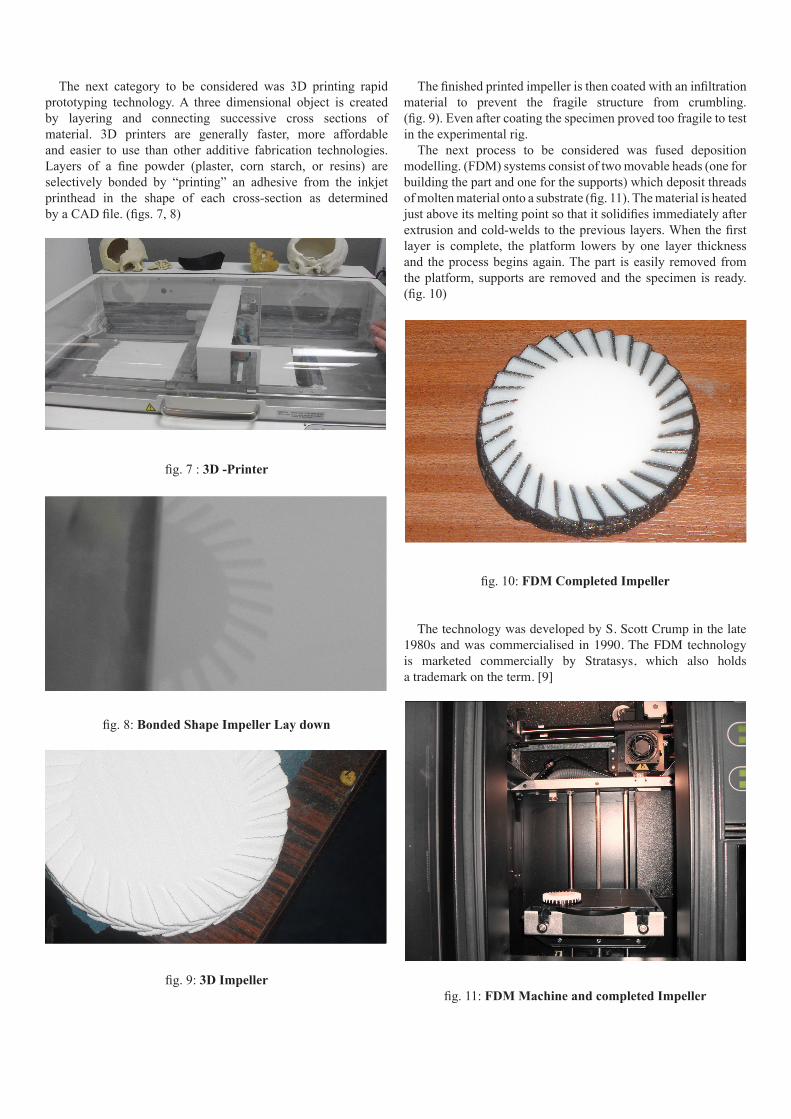
The next category to be considered was 3D printing rapid
prototyping technology.A three dimensional object is createdby layering and connecting successive cross sections of
material. 3D printers are generally faster, more affordable
and easier to use than other additive fabrication technologies.
Layers of a ine powder (plaster, corn starch, or resins) areselectively bonded by “printing” an adhesive from the inkjetprinthead in the shape of each cross-section as determined
byaCADile.(igs.7,8)
ig.7:3D -Printer
ig.8: Bonded Shape Impeller Lay down
ig.9: 3D Impeller
Theinishedprintedimpelleristhencoatedwithaniniltrationmaterial to prevent the fragile structure from crumbling.
(ig.9).Evenaftercoatingthespecimenprovedtoofragiletotestintheexperimentalrig.
The next process to be considered was fused deposition
modelling.(FDM)systemsconsistoftwomovableheads(onefor
buildingthepartandoneforthesupports)whichdepositthreads
ofmoltenmaterialontoasubstrate(ig.11).Thematerialisheatedjustaboveitsmeltingpointsothatitsolidiiesimmediatelyafterextrusionandcold-weldstothepreviouslayers.Whentheirstlayer is complete, the platform lowers by one layer thickness
and theprocessbeginsagain.Thepart iseasily removedfrom
theplatform,supportsare removedand thespecimen is ready.
(ig.10)
ig.10: FDM Completed Impeller
The technology was developed by S. Scott Crump in the late
1980s and was commercialised in 1990. The FDM technology
is marketed commercially by Stratasys, which also holds
a trademark on the term. [9]
ig.11: FDM Machine and completed Impeller

Severalmaterialsareavailablewithvaryingtrade-offsbetween
strength and temperature. As well as acrylonitrile butadiene
styrene(ABS)polymer, theFDMtechnologycanalsobeused
with polycarbonates, polycaprolactone, polyphenylsulfones
andwaxes.A“water-soluble”materialcanbeusedformaking
temporarysupportswhilemanufacturingisinprogress.Marketed
under the name WaterWorks by Stratasys this soluble support
material is actually dissolved in a heated sodium hydroxide
solutionwiththeassistanceofultrasonicagitation.[9]ABS,(C8H8·C4H6·C3H3N)n,isacommonthermoplasticused
tomakelight,rigid,moldedproductssuchgolfclubheads,(dueits
goodshockabsorbance).Itisacopolymermadebypolymerizing
styreneandacrylonitrile in thepresenceofpolybutadiene.The
proportions can vary from 15 to 35% acrylonitrile, 5 to 30%
butadieneand40to60%styrene.TheadvantageofABSisthat
thismaterialcombinesthestrengthandrigidityoftheacrylonitrile
and styrenepolymerswith the toughnessof thepolybutadiene
rubber.The most important mechanical properties ofABS are
resistanceandtoughness.Avarietyofmodiicationscanbemadetoimproveimpactresistance,toughness,andheatresistance.The
impactresistancecanbeampliiedbyincreasingtheproportionsof polybutadiene in relation to styrene and also acrylonitrile
althoughthiscauseschangesinotherproperties.
ADVANTAGESANDDISADVANTAGESOFTHERPPROCESSES
The FDM part was produced and run on test. However the
impeller blades broke apart and after close inspection it was
observed that theextrudedmaterialhadsmallvoidsacross the
bladethickness.Thiswasduetoinsuficientmateriallaydownasaresultoftherelativebladesize.(ig.12)
Oftheprocessesdescribed,onlytheFDMprocesswasableto
produceaspecimenfordirectuse.
ig.12: Failed FDM Impeller
To produce a mechanically stronger impeller FDM in
conjunction with RTV was considered. RT as previouslymentioned involves the production of moulds and tooling
inserts using RP. Room temperature vulcanizing (RTV) is
a relatively inexpensive and fast way to fabricate prototype
or pre-production tools. RTV tools are also known as silicone
rubbermoulds.ThemostwidelyusedformofRTVmouldingis
vacuumcasting.(ig.13)
Therangeofmaterialswithimprovedstrengthcharacteristics
andtheabilityofbetterillingoftheimpelllerproiletopreventvoidsincreaseswithRTV.Aporousorventedmoldisusedand
isplacedonatableorcontainerwherevacuumisapplied.The
liquid to be cast will be driven into the mold by atmospheric
pressure, while the vacuum will also remove trapped air that
would otherwise impede the free low of the liquid castingmaterial.
ig.13: RTV mould containing Impeller
Vacuum Casting is widely used for producing accurate
silicone tools for casting parts with ine details and very thinwalls. Vacuum castings are precise replicas of the patterns,
dimensionallyaccuratewithoutblemisheswithallproilesandtexturesfaithfullyreproduced.
Themaindificultytillthispointhadbeenproducingimpellerswithsuchsmalldimensionsthatcouldbeproducedmechanically
strong enough to survive the luid loading within the runningpump.
The vacuum casting process includes the following main
steps:
ig.14: FDM pattern
TheirststepistoproduceapatternusinganyoftheavailableRPprocesses(FDMinthiscase)(ig.14)
ig.15: Gated / vented blade.

The impeller blade with a chevron proile shown here, isprepared by adding venting and gating to the pattern; this is
neededasthevacuumisimposedduringcastingtoallowairto
escape(ig.15).
ig.16: Suspension and parting
Thepatternisitwithacastinggateandsetuponthepartingline,andthensuspendedinamouldcastingframe.Thepattern
needstohaveadequatemouldmaterialonallsidesandstillhave
thepartinglineidentiiedtofacilitateremoval(ig.16).
ig.17: Mould pouring
Once the two-part silicone-rubber is de-aerated and then
mixed, it is poured into the mould casting frame around the
pattern.(ig.17)
ig.18: Pattern removal
After curing the mould inside a heating chamber; the next
stage is the removalof thepattern fromthesiliconemouldby
cuttingalong theparting lineand thenclosingand sealing the
mould;(ig.18)Thecomputer-controlledequipmentmixesandpourstheresin
inside the vacuum chamber.As this takes place in a vacuum,
themouldisilledcompletelywithoutleavinganyairpocketsor
voids.TheMCPvacuumcastingrequiresinitialinvestmentina
vacuumchamberwithtwosections.
ig.19: Vacuum casting Impeller
Theuppersectionisformixingtheresinandthelowerisfor
castingtheresinintothemould.(ig.19)
ig.20: Impeller mould
Aftercuringthepartinaheatingchamberfor2–4hoursand
then removing it from the mould.After casting the resin, the
mouldismovedtotheheatingchamberforbetweentwotofour
hourstocuretheurethanepart.(ig.20).
ig.21: Removing gate risers
Thegateandrisersareremovedfromthecastingtomakean
exactcopyofthepattern.Afterhardening,thecastingisremoved
fromthesiliconemould.(ig.21)The introduction of RT technology enabled prototype,
pre-productionandinsomecasesfullproductiontoolingtobe
fabricatedwithsigniicantlyreducedtimeframes.
ÁUpperSection
ÁLowerSection

RESULTS
The success of the methodology has lead to further more
complexbladeproilesbeingassessed in theexperimental testprocedure.
Rapidprototypingtechniquesareextremelyusefulinhelping
thepumpdesignertoconductpreliminarytestingonalow-cost
prototype.Basedontheresultsobtained,theabilitytomodifyor
improvethedesignsbeforeresortingtomorecostlyfabricating
methods has proved extremely beneicial in this currentresearch.
TheresultshaveshownthatFDM/RTVisaviableandfeasible
methodofproducingprototypesfortesting.Furtherreinementsofthetechniquearecurrentlybeingpursuedsothatthesurface
inish,isenhancedwhilstmaintainingtheaccuracyofthepartsproduced.
Preliminary results demonstrate that the impellers have the
potentialtoimprovethepumpeficiency.
ig.22: Regenerative Pump Results
Whilst the process has demonstrated reasonable success in
producing viable test samples, theFDM/RTVmethod several
disadvantages. Surface inish and the need for a two stagemanufacturing process (FDM then RTV). Limited range of
materials availablemeant that a newmethodof photopolymer
setting will be considered in the future.This will increase the
rangeofmaterialsforselection,improvesurfaceinishanddeletetheneedtouseRTV.
The helical motion of the luid within the pump is bestprescribed by low visualisation work carried out in the1940’sand1950’s.[4,8,10]Theworkpresentedinthispaperdemonstrates interesting correlation to these observed tests in
awaythathasn’tbeenachievedmathematicallytodate.
However the results achieved using the FDM/RTV
methodology have successfully lead to the optimisation of the
pump in an effective manner. (ig. 22)
CONCLUSIONS
There are a number of conclusions which may be drawn
with regard to effectively matching the regenerative pump
CFDmodelwith theexperimentaldata.CFDresultsproduced
areasonablerepresentationof thelowinaregenerativepumpandarebeingutilisedtofocusinvestigationforunitperformance
improvement (ig. 22).As the capabilities ofCFDcontinue todevelop,itistobeexpectedthattheuncertaintiesassociatedwith
CFDpredictionshouldalsoreduce.Attheveryleastitistobe
expected that there will be a continuing growth in processing
powerfortheforeseeablefuture,whichwillreduceandperhaps
remove the geometric simpliications which have to currentlybe made. The ability to test and validate the models is only
possible through detailed experiments. This work has been
usefultonotonlybenchmarkcurrentregenerativepumpdesign,
butgivesconidenceintheabilityofCFDoptimisationforthedesign to increase the performance of the pump in the future
[12,13,].Theindingsofthisoptimisationworkwillbepresentedin a future paper. The remarkable increase in the number of
commerciallyavailableRPandRTsolutionssincethe1990sbyadvancesinthree-dimensionalCADmodelling,computeraided
manufacturing,computernumericalcontrolandthedevelopment
ofnewmaterials,arethereasonthisworkproceeds.
ACKNOWLEDGEMENTS
TheauthorswouldliketoexpressgratitudetoMr.DrewIrvine,
Mr.TomFarmer,Mr.DuncanLindsayandMr.DaveCunningham
for their help and assistance in the impeller manufacturing
processes.
REFERENCES
1. EUROPEAN PARLIAMENT. “Establishing a framework
for the settingofecodesign requirements forenergy-using
products”,DIRECTIVE2005/32/EC(2005)
2. BADAMI, M: “Theoretical and experimental analysis oftraditional and new peripheral pumps” SAE Technical
PapersSeries,No971074(1997)3. ENGEDA,A.: “Flow analysis and design suggestions for
regenerative low pumps” ASME FEDSM2003-45681(2003)
4. ENGELS, H.: “Untersuchungen an Ringpumpen ”, TechHochHannover.1(1940)
5. RAHEAL,M.,ENGEDA,A.,:“Systematicdesignapproachfor radial blade regenerative turbomachines” Journal for
PropulsionandPowerVol.21(2005)
6. SENOO,Y“TheoreticalresearchonFrictionPump”Institute
ofFluidEngineeringVol5No1pp23-48(1948)7. SONG, J. W., ENGEDA, A., CHUNG, M.K, “Modiied
theoryforthelowmechanisminaregenerativelowpump”ProceedingsIMECHE,Vol217(2003)PowerandEnergy
8. WILSON, W.A., SANTALO, M.A., OELRICH, J.A.: “ATheory of the luid dynamic mechanism of regenerativepumps”Trans.ASMENo.8(1955)
9. STRATASYSWebpage,StratasysInc.,EdenPrairie,min-
nesota,2001,www.stratasys.com
10. IVERSON, H.W.: “Performance of the Periphery Pump”–ASMEVol7pp19-22(1955)
11. MEAKHAIL, T., PARK, S.O,.: “An Improved theory forregenerativepumpperformance.”IMECHEVol219PartA(2005)
12. SHIH,T.H., LIOU,W.W., SHABBIR,A.,YANG, Z., and
ZHU, J., , “A New k-ε Eddy-Viscosity Models for High
Reynolds Number Turbulent Flows-Model Development
and Validation”, Computers Fluids, 24 (3), pp. 227-238.
(1995)13. SPALART, P., “.Trends in turbulence treatments” .AIAA
paper(AIAA2000-2306)(2000)
Regenerative Pump
0
5
10
15
20
25
30
35
40
45
50
0 0.1 0.2 0.3 0.4 0.5 0.6
Flow Coefficient
Effic
iency
Expt
CFD