Development of a precast concrete bent-cap system Journal... · · 2017-03-29n This paper...
26
May–June 2008 | PCI Journal 74 Editor’s quick points n This paper summarizes the development of a precast concrete bent-cap system to connect precast concrete bent caps to cast- in-place columns or precast concrete trestle piles in nonseismic regions. n Four connection types were explored, including grout pockets, grouted ducts, grouted sleeve couplers, and bolted connections. Development of a precast concrete bent-cap system Eric E. Matsumoto, Mark C. Waggoner, Michael E. Kreger, John Vogel, and Lloyd Wolf As the need to rapidly build short- and moderate-span bridges in increasingly congested urban environments and at water crossings grows throughout the United States, development of precast concrete bridge substructures has been sought to reduce construction time, minimize the traf- fic and environmental impacts, and improve quality and durability. The impact and costs associated with traffic control and disrupted traffic flow continue to grow, as do concerns about public and worker safety in construction zones. Pre- cast concrete bridge construction on large projects or over water crossings has proved to be faster, less costly, and of higher quality because small improvements in productivity are multiplied by repetitive operations. Also, the unit costs associated with setting up precast concrete operations are relatively small. The development of a reliable precast concrete bent-cap system is expected to be an important step in the advance- ment of precast concrete substructures. Not only will such a system reap the benefits of reduced construction time and traffic disruption, but it will also allow the controlled conditions at precast concrete plants to be exploited, enabling the efficient production of high-quality caps and facilitating the use of high-performance concrete. In addi- tion, a precast concrete bent-cap system can accommodate special construction conditions, such as sites with difficult access or sensitive environments, more easily than cast-in- place systems. Precast concrete in practice Figures 1 and 2 show two recently constructed bridges in Texas for which precast concrete bent caps were advan- tageously used as part of a non-integral bent-cap system, that is, without moment continuity between the superstruc- ture and substructure. 1,2 In 2000, the Texas Department 74
Transcript of Development of a precast concrete bent-cap system Journal... · · 2017-03-29n This paper...

May–June 2008 | PCI Journal74
Editor’s quick points
n This paper summarizes the development of a precast concrete bent-cap system to connect precast concrete bent caps to cast-in-place columns or precast concrete trestle piles in nonseismic regions.
n Four connection types were explored, including grout pockets, grouted ducts, grouted sleeve couplers, and bolted connections.
Development of a precast concrete bent-cap systemEric E. Matsumoto, Mark C. Waggoner, Michael E. Kreger, John Vogel, and Lloyd Wolf
As the need to rapidly build short- and moderate-span bridges in increasingly congested urban environments and at water crossings grows throughout the United States, development of precast concrete bridge substructures has been sought to reduce construction time, minimize the traf-fic and environmental impacts, and improve quality and durability.
The impact and costs associated with traffic control and disrupted traffic flow continue to grow, as do concerns about public and worker safety in construction zones. Pre-cast concrete bridge construction on large projects or over water crossings has proved to be faster, less costly, and of higher quality because small improvements in productivity are multiplied by repetitive operations. Also, the unit costs associated with setting up precast concrete operations are relatively small.
The development of a reliable precast concrete bent-cap system is expected to be an important step in the advance-ment of precast concrete substructures. Not only will such a system reap the benefits of reduced construction time and traffic disruption, but it will also allow the controlled conditions at precast concrete plants to be exploited, enabling the efficient production of high-quality caps and facilitating the use of high-performance concrete. In addi-tion, a precast concrete bent-cap system can accommodate special construction conditions, such as sites with difficult access or sensitive environments, more easily than cast-in-place systems.
Precast concrete in practice
Figures 1 and 2 show two recently constructed bridges in Texas for which precast concrete bent caps were advan-tageously used as part of a non-integral bent-cap system, that is, without moment continuity between the superstruc-ture and substructure.1,2 In 2000, the Texas Department
74

75PCI Journal | May–June 2008
personnel could work more easily from the ground.
The PCI-award-winning crossing over Lake Belton on SH 36 near Temple, Tex., also used precast concrete bent caps as part of the replacement of a geometrically and structur-ally deficient two-lane bridge (Fig. 2). The 3840-ft-long (1170 m) and 84-ft-wide (26 m) precast, prestressed concrete U-beam superstructure is supported by a hammer-head, double-column, bent substructure. Precast concrete bent caps provided key advantages to the project by
saving time and removing on-site construction activi-•ties, such as formwork construction and removal, reinforcing steel and concrete placement, and concrete cure time, from the schedule’s critical path;
saving money by making the caps easier to build and •by streamlining labor at both the precasting yard and the bridge site, which also resulted in an economy of scale for the 62 identical bent caps;
improving quality by allowing the caps to be precast •in the controlled environment of the precasting yard where internal concrete temperatures could be readily monitored during curing;
improving work-zone safety by reducing the time •that workers and inspectors were required to spend at significant heights (50 ft [15 m]) over water;
eliminating traffic disruptions by allowing the existing •structure to remain in service while the new bridge was being built;
of Transportation (TxDOT) began replacing the narrow two-lane crossings of State Highway (SH) 66 over Lake Ray Hubbard near Dallas, Tex., with a pair of conventional prestressed concrete I-beam bridges with lengths up to 10,280 ft (3033 m).
The contractor requested to precast the substructure’s concrete bent caps on site as an alternative to the original cast-in-place design. This would accelerate construction of the 43 consecutive bents, avoid the difficulties in handling formwork and materials over water, and minimize the exposure of workers to power lines near the south side of the eastbound structure.
Four-inch-diameter (100 mm) steel corrugated ducts were precast at full height into the cap. These ducts housed six no. 11 (36M), grade 60 (420 MPa) reinforcing bars that extended from the tops of the cast-in-place concrete col-umns. Spiral confinement was also used around the ducts. A special template formed the final lift of concrete for the columns and helped accurately locate the projecting con-nection dowels. Figure 1 shows the friction collars placed on the columns to support a work platform and provide temporary support and grade adjustment for the 30 ton (27 tonne) caps. Once the cap was at the desired grade, special circular collar forms were placed at the bedding layer be-tween the cap and column to aid in pressure grouting.
The contractor averaged placement of one bent per day, saving about six months over traditional cast-in-place construction. In addition, work-zone safety was improved because about 80% of the bent construction work was per-formed on the ground rather than over water, and a higher-quality product resulted because contractor and inspection
Figure 1. A precast concrete bent-cap system is used in State Highway 66 crossing over Lake Ray Hubbard near Dallas, Tex.
Precasting of concrete bent cap using grouted-duct connection Lowering of precast concrete bent cap onto friction collars

May–June 2008 | PCI Journal76
facilitating aesthetic treatment of the bent caps for the •recreational lake.
Designers replaced the clutter of a typical multicolumn substructure with essentially a single-column bent (Fig. 2). The 39-ft-long (12 m) caps incorporated a curved bottom soffit that varied in depth from 3.0 ft (0.9 m) to 5.5 ft (17 m) and supported three or four lines of TxDOT Type 54, 120-ft-long (37 m) U-beams. The precast concrete cap weight of about 75 tons (68 tonnes) was nearly equivalent to that of the U-beam.
The connection between the cap and column used a pattern of twelve no. 11 (36M), grade 60 (420 MPa) reinforcing bars and two 13/8-in.-diameter (35 mm) threaded bars for each connection. Dowels were housed in 4.5-in.-diameter (110 mm) corrugated steel ducts that did not extend full height to avoid congestion with negative-moment bent-cap reinforcement and to mitigate potential durability problems associated with exposed grout surfaces at the top of the cap. The threaded bars extended full height to provide tem-porary support of the cap prior to completion of connection grouting. Caps were set on 2-in.-thick (50 mm) steel shims, and after placement of dry-pack grout, the bedding layer and ducts were pressure grouted.
Both the Lake Ray Hubbard and Lake Belton bridges were designed and built based on the research summarized in this paper. Other transportation departments and research-ers have also developed and implemented precast concrete bridge systems, including substructures,3–5 and though some owners have implemented precast concrete bent caps,6–8 limited experimental work has been conducted to examine and synthesize the critical design, fabrication, and
construction issues associated with precast concrete bent-cap systems. Recently, however, the National Cooperative Highway Research Program (NCHRP) funded project 12-74, Development of Precast Bent Cap Systems for Seismic Regions. Based in part on the research presented in this paper, NCHRP 12-74 intends to further the devel-opment of precast concrete bent-cap systems, extending their use to all regions of the United States, regardless of seismic activity.9,10
Research approach
Use of precast concrete bent-cap systems before 1996 revealed uncertainties related to behavior, design, detail-ing, construction, and durability. Realizing the potential benefits as well as uncertainties, TxDOT, through the Center for Transportation Research (CTR) at the Univer-sity of Texas at Austin (UT), initiated CTR project 1748, Design and Detailing of a Precast Bent Cap System,11 with the following objectives:
Develop practical, cost-effective candidate details for •connecting precast concrete bent caps to cast-in-place concrete columns and precast concrete trestle piles.
Test selected connection details to examine connec-•tion constructability and behavior under loading.
Develop a design methodology, example details, and •construction guidelines for precast concrete bent-cap systems.
The scope of research was limited to conventional bridge systems predominant in Texas, including precast con-
Figure 2. A precast concrete bent-cap system is used in the crossing of State Highway 36 over Lake Belton, northwest of Temple, Tex.
Lowering of precast concrete bent cap Completed bridge
76

77PCI Journal | May–June 2008
Figure 3. Precast concrete bent-cap connections include grout pockets, grouted ducts, and bolted connections. The grouted sleeve couplers are not shown. Note: 1 in. = 25.4 mm.
SHIMS * 18 IN., MAXIMUMASPECT RATIO = 1:2 MAXIMUM10˚ OF COLUMN AREA MAXIMUM
CENTERLINE BENT CAP
CENTERLINE SQUARECOLUMN AND GROUT POCKET
FLEXURAL STEEL
PLAN
TOP OF CAP
FLEXURAL STEEL
SIDE REINFORCEMENT
FLEXURAL STEEL
CENTERLINE SHIMS
SQUARE COLUMN
STIRRUP TYPICAL
SPIRAL AT 4 IN. PITCH
REINFORCING BARCONNECTORS
ELEVATION
TOP OF CAP GROUT
AIR VENT 2˚ SLOPE MINIMUMTYPICAL
GROUT POCKETSEE DETAIL
SQUARE COLUMNCORRUGATED DUCTS ORDRILL AND GROUT (TYPICAL)
SECTION
3½ IN
. TO
5½ IN
. REC
ESS
OPTI
ONAL
ALL
CON
NECT
IONS
2 IN
. TO
5 IN
.EM
BEDM
ENT
SHIMS * 18 IN., MAXIMUMASPECT RATIO = 1:2 MAXIMUM10˚ OF COLUMN AREA MAXIMUM
CENTERLINE BENT CAP
FLEXURAL STEEL
FLEXURAL STEEL
FLEXURAL STEEL
SIDE REINFORCEMENT
STIRRUP TYPICAL
SPIRAL AT 4 IN. PITCH
CENTERLINE SHIMSREINFORCING BAR CONNECTORSTYPICALROUND COLUMN
ELEVATION
PLAN
TOP OF CAP
AIR VENT 2˚ SLOPE MINIMUMTYPICAL
GROUT POCKET
GROUT
CORRUGATED DUCTS ORDRILL AND GROUT (TYPICAL)
1 IN. TO 2 IN. GROUT THICKNESS
ROUND COLUMN
REINFORCING BAR CONNECTORS
SECTION
Single-line grout pocket (embedment option) Double-line grout pocket (surface flush option)
CENTERLINE ROUNDCOLUMN AND GROUT POCKET
22
TOP OF CAP
Grouted duct (embedment option) Bolted connection (surface flush option)
SHIMS * 18 IN. MAXIMUMASPECT RATIO = 1:2 MAXIMUM10˚ OF COLUMN AREA MAXIMUM
CENTERLINE BENT CAP
FLEXURAL STEEL
PLAN
CENTERLINE SQUARE COLUMN
CENTERLINE 4 CORRUGATED METAL DUCTS
TOP OF CAP
FLEXURAL STEEL
FLEXURAL STEEL
SIDE REINFORCEMENT
CENTERLINE SHIMS
SQUARE COLUMNREINFORCING BAR CONNECTORS
STIRRUP TYPICAL
SPIRAL AT 4 IN. PITCH
GROUT
ELEVATION
AIR VENT
CORRUGATEDMETAL DUCTS
CORRUGATED DUCTS ORDRILL AND GROUT (TYPICAL)SQUARE COLUMN
3½ IN
. TO
5½ IN
. REC
ESS
OPTI
ONAL
ALL
CON
NECT
IONS
2 IN
. TO
5 IN
.EM
BEDM
ENT
SECTION
SHIMS * 18 IN. MAXIMUMASPECT RATIO = 1:2 MAXIMUM10˚ OF COLUMN AREA MAXIMUM
CENTERLINE SQUARE COLUMN
CENTERLINE CORRUGATED METAL DUCTS
FLEXURAL STEEL
CENTERLINE BENT CAP
STIRRUP (TYPICAL)
SPIRAL AT 4 IN. PITCH
FLEXURAL STEEL
SIDE REINFORCEMENT
FLEXURAL STEEL
TOP OF CAP
PLAN
AUXILIARYREINFORCEMENT
CENTERLINE SHIMSSQUARE COLUMN
THREADED RODCONNECORSTYPICAL
ELEVATION
CORRUGATEDMETAL DUCTS
TOP OF CAP
THREADED ROD CONNECTORSWITH PLATE AND NUT
AIR VENT GROUT DUCT
GROUT
CORRUGATED DUCTS ORDRILL AND GROUT (TYPICAL)
SQUARE COLUMN
1 IN
. TO
2 IN
.GR
OUT
THIC
KNES
S
SECTION
22

May–June 2008 | PCI Journal78
Table 2 summarizes construction sequences used for placement of precast concrete caps in two Texas bridges. As mentioned, the Lake Belton Bridge used precast concrete caps with cast-in-place columns,1,2 and the Red Fish Bay Bridge used precast concrete caps with precast concrete trestle piles.6 Both friction collars and shims have been used to aid in cap-setting operations. In addition, prepackaged, nonshrink, high-strength cementitious grout and shrinkage-compensating concrete have been used for filling the precast concrete voids after cap placement. Variations of these construction sequences have been used on other bridges as well.11
Three-phase experimental program
To address uncertainties identified by the IRC, a three-phase experimental research program was developed to in-vestigate and refine grout-pocket, grouted-duct, and bolted connection details. Phase 1 used 32 large-scale pullout tests to examine the behavior and failure modes of grout-pocket and grouted-duct connections. Phase 2 involved four full-scale, bent cap–to–column connection tests of grout-pocket, grouted-duct, and bolted connections. Phase 3 included construction and testing of two full-scale bents at the construction yard of a highway contractor. This paper, which is limited to phase 1 test results, significantly expands on results reported elsewhere.12,13 Phase 2 and 3 results, the design methodology, and a precast concrete connection construction specification will be presented in a future publication.
Phase 1 pullout tests
The primary objective of phase 1 tests was to experi-mentally investigate anchorage behavior of straight and headed reinforcing bars embedded within grout pockets and grouted ducts using pullout tests. Connectors in an actual precast concrete bent-cap system are subjected to a complicated state of stress. However, the first phase of experimental research subjected connectors to monotonic tension. This allowed fundamental bond and load-deflec-tion characteristics of grouted reinforcing bars to be clearly assessed and a large number of variables to be investi-gated. Results were then used and verified in phase 2 and 3 connection tests, providing a sufficiently conservative basis for the design methodology.
Test matrix
As shown in the test matrix of Table 3, a total of 32 pullout tests were conducted for three types of specimens: single-line grout pockets, double-line grout pockets, and grouted ducts. Primary test variables included reinforcing-bar size and embedment depth hef. Because of the difficulty in scaling bond behavior, larger no. 8 (25M) and no. 11 (36M) reinforcing bars, representing full-scale-connection
crete bent caps on cast-in-place columns in multicolumn bents and precast concrete trestle piles. Bents subjected to seismic or other highly dynamic loads or bents of unusual proportions or configurations were not addressed. In addi-tion, priority was placed on systems that use simple con-struction operations and provide maximum construction tolerances. Therefore, post-tensioning of connections and bent caps and the use of match casting, precast concrete columns, or other more complex options were intentionally not included.
Connection details
To accomplish the first objective, connection details were developed in coordination with an industry review com-mittee (IRC) that included representatives of the precast concrete and construction industries as well as TxDOT en-gineers. Discussions led to the development and selection of four connection types—grout pockets, grouted ducts, grouted sleeve couplers, and bolted connections—for use in rectangular or inverted-tee bent caps. Figure 3 shows sample details for grout-pocket, grouted-duct, and bolted connections.
Grout-pocket connections derive their name from the fact that they incorporate one or more precast concrete voids, or pockets, in the bent cap to receive the column connectors (dowels). Depending on their size, voids are typically filled with grout or small-aggregate concrete.
As shown in Fig. 1 and 2, the grouted-duct connections used partial- or full-height steel corrugated ducts embed-ded in the bent cap to house column connectors, which were grouted with prepackaged, high-strength, nonshrink cementitious grout. Grouted sleeve couplers used propri-etary couplers that are typically pumped with nonshrink, metallic grout. Bolted connections were a variation of grouted-duct connections using full-depth dowels that were anchored at the cap top. To minimize bent-cap size and congestion, dowels extending from the core of the column or pile were used for the connection rather than extending column or pile longitudinal reinforcement.
CTR project 174811 summarizes design criteria related to economics, constructability, durability, and force transfer used in developing and refining details. Table 1 summariz-es advantages and disadvantages of each connection type based on constructability, force transfer, and durability criteria. Practice in Texas has demonstrated that advantag-es outweigh disadvantages for all connection types except grouted sleeve couplers. The use of proprietary couplers, with their cost and associated tight construction tolerances, led the IRC to conclude that such connections are not economical for Texas highway applications, though other regions of the United States have successfully used such connections with the aid of templates and precise fabrica-tion and placement.

79PCI Journal | May–June 2008
reinforcing bars, were used. Embedment depth varied from 5 to 18 reinforcing-bar diameters (5db to 18db) to exhibit both brittle and ductile failure modes. Other variables in-cluded multiple reinforcing bars (group effects, transverse and longitudinal loading), confining reinforcement, grout extension (neat and added pea gravel), and grout brand.
Straight and upset-headed reinforcing bars were selected as connectors for cost-effectiveness and anchorage. Figure 4 shows a straight reinforcing bar and an upset-headed re-inforcing bar with epoxy coating.14 The small head, which had a diameter of 1.4 times the reinforcing-bar diameter, provided additional anchorage without requiring exces-sive construction tolerances for precast concrete connec-
Table 1. Advantages and disadvantages for four precast concrete bent-cap connection types
Connection type
Advantage or disadvantage
Constructability Durability Force transfer
Grout pocket
Advantages
• Large construction tolerances • Tailored pocket shapes • Easy-to-place confining reinforcement • Simple grouting operations
• Epoxy-coated connectors viable
• Simple-to-tailor number of connectors • Excellent interlock without surface roughening • Excellent anchorage of connectors • Excellent ductility of connectors • Simple anchorage design approach
Disadvantages• Congestion of reinforcement • Large spacing between reinforcement
• Cracking at large top surface • Cracking through connectors
• Potentially small rotational stiffness
Grouted duct
Advantages
• Acceptable construction tolerances • Inexpensive stay-in-place ducts • Minimal interference with cap reinforcement • Easy-to-place confining reinforcement
• More limited exposed top surface • Well-protected connectors • Epoxy-coated connectors viable
• Excellent interlock at all interfaces • Excellent anchorage of connectors • Excellent ductility of connectors • Simple anchorage design approach
Disadvantages• Complex grouting operations
— • Potentially small rotational stiffness
Grouted sleeve coupler
Advantages• Minimal interference with cap reinforcement
• Well-protected connectors • Epoxy-coated connectors viable
• Excellent anchorage of connectors • Excellent ductility of connectors
Disadvantages
• Tight horizontal tolerances • Proprietary hardware and grout • High skill level required • Grout pumping required • Multiple grouting operations
—
• Potentially small rotational stiffness
Bolted connection
Advantages
• Acceptable construction tolerances • Inexpensive stay-in-place ducts • Minimal interference with cap reinforcement • Easy-to-place confining reinforcement • Cap-setting option with leveling nuts and plates • Temporary support during erection • Optional post-tensioning
• Galvanized connectors viable • Optional post-tensioning
• Resistance to large moments possible • Full continuity of bars through connection • Load path redundancy by bond and anchorage • Excellent ductility of connectors • Anchorage design not required for cap
Disadvantages• Complex grouting operations • Multiple grouting operations
• Grouting of cap top recess • Exposed cap top anchorage
• Potentially small rotational stiffness
Figure 4. These upset-headed and straight reinforcing bars with epoxy coating were used in testing.

May–June 2008 | PCI Journal80
tions. For headed reinforcing bars, the embedment depth is defined as the depth that the reinforcing bar is embedded into the grout pocket or duct without including the head. Epoxy-coated reinforcing bars were used in all tests to provide a conservative basis for development of anchorage equations for all types of deformed reinforcing bars.
Test specimens
Grout-pocket specimens were 2 ft × 2 ft × 12 ft (0.6 m × 0.6 m × 3.7 m) beams, representative of a full-scale con-nection for a single-line grout pocket in a trestle pile bent and about three-quarters scale for double-line pockets.
Figure 5 shows examples of the reinforcement cages and formwork for the grout-pocket specimens. Based on precast concrete caps used in the Red Fish Bay Bridge,6 a longitudinal reinforcement ratio of about 0.5% (top and bottom) for the beams was used. However, stirrups were eliminated in the connection region to prevent possible contribution to the pullout capacity or ductility.
Single-line grout pockets used one line of connectors, whereas double-line grout pockets used two lines (Fig. 3). Single-line grout-pocket inserts incorporated a single 5- degree taper through the depth of the cross section to
enhance anchorage of the pocket within the cap. A small 1-degree taper was included along the length of the cap to facilitate form removal. Double-line grout pockets were nearly vertical through the cross section to allow ample space for two pockets, but they incorporated a 7-degree taper along the length. Pockets were inverted to facilitate loading of the reinforcing bars in the test setup.
Confining reinforcement was placed between the top and bottom layers of longitudinal reinforcement for single-line and double-line grout-pocket tests that loaded two rein-forcing bars. As shown in Fig. 6 and Table 4, two confine-ment options were investigated for the single-line grout pockets: spiral reinforcement and welded-wire reinforce-ment.
Grouted duct specimens were 30 in. (0.75 m) deep and incorporated nominal 4-in.-inside-diameter (100 mm) corrugated-steel ducts through the beam depth. Figure 7 shows the reinforcement and ducts for the grouted duct specimens.
Grouting
Based on a series of trial batches, three proprietary, prepackaged, nonshrink cementitious grouts (brands A, B, and C) were selected for use. However, to maintain a reasonable scope of testing, brand A was used for most tests, with brands B and C used for a limited number of tests to compare performance of grouts, including neat and extended grouts.
Gravity-flow grouting was used for test specimens. The grout pockets were grouted with a bucket while the grouted ducts were grouted with a tremie tube to represent the simplest field-grouting approaches.
Table 2. Example construction sequences for precast concrete bent cap
Hammerhead bent with grouted-duct connection
(Lake Belton, Tex.)
Trestle pile bent with grout-pocket connection
(Red Fish Bay, Tex.)
Place and secure dowels at 1. column top with template during casting of columns
Place shim pack at column 2. top and verify elevation
Lower cap over dowels onto 3. shims and adjust cap elevation
Tighten select threaded bars 4. at cap top to provide tempo-rary support for cap
Form bedding layer between 5. column and cap
Grout bedding layer and ducts 6. through grout ports at bed-ding layer
Remove bedding layer form 7. and temporary cap-top anchorage
Cast piles with embedded 1. sleeves
Drive piles with template 2. and break back to desired elevation
Grout dowels into embedded 3. sleeves
Attach friction collar and 4. verify elevation
Lower cap over dowels onto 5. friction collar
Form bedding layer between 6. piles and cap
Grout bedding and pockets 7. through opening at cap top
Remove bedding layer form8.
Figure 5. These reinforcement cages and formwork were used for grout-pocket specimens.
Single-line grout pocket Double-line grout pocket
81PCI Journal | May–June 2008
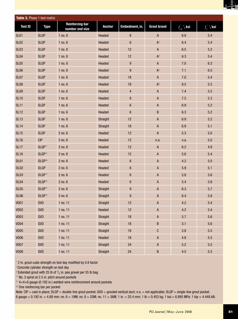
Table 3. Phase 1 test matrix
Test ID TypeReinforcing bar number and size
Anchor Embedment, in. Grout brand fcg' *, ksi f
c' †, ksi
SL01 SLGP 1 no. 8 Headed 6 A 6.9 5.4
SL02 SLGP 1 no. 8 Headed 6 A‡ 6.4 5.4
SL03 SLGP 1 no. 8 Headed 12 A 6.5 5.2
SL04 SLGP 1 no. 8 Headed 12 A‡ 6.3 5.4
SL05 SLGP 1 no. 8 Headed 9 A 7.0 6.3
SL06 SLGP 1 no. 8 Headed 9 A‡ 7.1 6.5
SL07 SLGP 1 no. 8 Headed 18 A 7.0 5.4
SL08 SLGP 1 no. 8 Headed 18 A‡ 8.5 5.5
SL09 SLGP 1 no. 6 Headed 4 A 7.4 5.5
SL10 SLGP 1 no. 6 Headed 8 A 7.5 5.3
SL11 SLGP 1 no. 6 Headed 6 A 6.9 5.2
SL12 SLGP 1 no. 6 Headed 6 B 6.3 5.2
SL13 SLGP 1 no. 8 Straight 12 A 6.9 5.2
SL14 SLGP 1 no. 8 Straight 18 A 6.9 5.1
SL15 SLGP 2 no. 8 Headed 12 A 5.3 5.0
SL16 CIP 2 no. 8 Headed 12 n.a. n.a. 5.0
SL17 SLGP** 2 no. 8 Headed 12 A 6.2 4.9
SL18 SLGP†† 2 no. 8 Headed 12 A 5.6 5.4
DL01 DLGP‡‡ 2 no. 6 Headed 6 A 4.2 5.0
DL02 DLGP 2 no. 6 Headed 6 A 5.9 5.1
DL03 DLGP** 2 no. 6 Headed 6 A 5.8 5.6
DL04 DLGP†† 2 no. 6 Headed 6 A 5.4 5.6
DL05 DLGP** 2 no. 6 Straight 9 A 6.3 5.7
DL06 DLGP†† 2 no. 6 Straight 9 A 6.4 5.8
VD01 GVD 1 no. 11 Straight 12 A 4.2 5.4
VD02 GVD 1 no. 11 Headed 12 A 4.2 5.4
VD03 GVD 1 no. 11 Straight 18 A 5.7 5.6
VD04 GVD 1 no. 11 Straight 18 B 3.1 5.6
VD05 GVD 1 no. 11 Straight 18 C 3.8 5.5
VD06 GVD 1 no. 11 Headed 18 A 4.8 5.5
VD07 GVD 1 no. 11 Straight 24 A 5.2 5.5
VD08 GVD 1 no. 11 Straight 24 B 4.5 5.5
* 2 in. grout-cube strength on test day modified by 0.8 factor † Concrete cylinder strength on test day ‡ Extended grout with 25 lb of 3/8 in. pea gravel per 55 lb bag ** No. 3 spiral at 2.5 in. pitch around pockets †† 4×4×6 gauge (0.192 in.) welded-wire reinforcement around pockets ‡‡ One reinforcing bar per pocket Note: CIP = cast in place; DLGP = double-line grout pocket; GVD = grouted vertical duct; n.a. = not applicable; SLGP = single-line grout pocket. 6 gauge = 0.192 in. = 4.88 mm; no. 6 = 19M; no. 8 = 25M; no. 11 = 36M. 1 in. = 25.4 mm; 1 lb = 0.453 kg; 1 ksi = 6.895 MPa; 1 kip = 4.448 kN.

May–June 2008 | PCI Journal82
gauges were also placed on vertical ducts to measure the duct strain. In addition to the load, strain, and deflection, crack widths were also measured.
Test reinforcing bars were loaded monotonically in tension in 2-kip increments (9 kN) with a hand-operated hydraulic pump. After each load increment, the active channels were scanned and the voltage was recorded. Specimens were load-ed until either a concrete or connector failure occurred.
Headed reinforcing bars in grout pockets
Observed behavior Two primary failure modes occurred for headed reinforcing bars in grout pockets: a brittle concrete breakout failure prior to reinforcement yielding and a ductile failure in which the reinforcement yielded prior to concrete breakout. In some cases, a concrete breakout surface devel-oped after reinforcement yielding but prior to fracture.
Anchor response was characterized by development of splitting cracks in the grout pocket after initial bond asso-ciated with adhesion and friction was lost. The reduction in bond along the reinforcing bar caused a transfer of load to the head and a reduction in stiffness, as shown in the load-slip response for a single headed reinforcing bar embedded 12 in. (300 mm) in a single-line grout pocket (Fig. 11).
Test setup, instrumentation, and loading
Figure 8 shows the self-equilibrating test setup used for grout-pocket and grouted-duct tension pullout tests. Back-to-back channels supported 60 ton (54 tonne), center-hole hydraulic rams, 100-kip-capacity (450 kN) load cells, and a wedge and chuck assembly. Three crossbeams sup-ported the channels on the top of the specimen and were positioned at a distance of about 1.5 times the maximum connector embedment depth from the test reinforcing bar to minimize confinement effects. Figure 9 shows ram configurations used for single-line and double-line grout-pocket tests that incorporated multiple reinforcing bars, representing connector configurations used for resisting moments developed in the longitudinal or transverse direc-tion of a bridge.
Behavior during pullout tests was based on active measure-ments. A data-acquisition system actively measured the load, strain, and deflection for the pullout tests. Figure 10 is a schematic of the active instrumentation for headed-reinforcing-bar tests. For grouted-duct specimens, strain
Table 4. Phase 1 confining reinforcement
Connection type Confinement Description Volumetric ratio, %
Single-line grout pocket
Spiral No. 3 at 2.5 in., 18 in. diameter 0.96
Welded-wire reinforcement4 x 4 x 6 gauge, 17¼ in. x 12¼ in. x 18 in.
0.20
Double-line grout pocket
Spiral No. 3 at 2.5 in., 20½ in. diameter 0.86
Welded-wire reinforcement4 x 4 x 6 gauge, 15½ in. x 22 in. x 18 in.
0.16
Note: 1 in. = 25.4 mm; no. 3 = 10M; 6 gauge = 0.192 in. = 4.88 mm.
Figure 6. These confinement options were used for single-line grout pockets.
Welded-wire reinforcement Spiral
Figure 7. This reinforcement cage and ducts were used for the grouted-duct specimens.
Ducts in reinforcement cage Plan view of covered ductprior to casting

83PCI Journal | May–June 2008
Figure 8. This test setup is for grout-pocket and grouted-duct tension pullout tests.
Figure 9. These drawings show the ram configurations for the grout-pocket pullout tests.
Figure 10. This schematic of phase 1 instrumentation is for the headed- and straight-reinforcing-bar tests.
Angle section
Test bar
= Spring-loadedlinear potentiometer
= Strain gauge
Coppertube
sheathing
Threadedrod
Bracket
String-type linearpotentiometers
Neoprene pad
Single-line grout pocket
Double-line grout pocket(longitudinal)
Double-line grout pocket(transverse)

May–June 2008 | PCI Journal84
At a larger load, splitting cracks extended from the grout into the beam and developed at re-entrant corners of the
pocket, gradually reducing the confining effect of the surrounding concrete on the grout pocket. Corner cracks then combined with failure planes extending from the reinforcing-bar head to form a failure surface. The lead end of the reinforcing bar (at the top surface) yielded prior to formation of the concrete breakout surface.
Figure 12 plots the reinforcing-bar force at the head, as in-ferred from strain-gauge measurements versus applied load. This demonstrates the load transfer from the reinforcing-bar shaft to the head as load increased and bond degraded along the reinforcing bar. The relative portion of load carried by the head increased significantly just prior to failure. The use of smooth, inclined grout-pocket surfaces did not result in slip between the grout pocket and surrounding concrete. Figure 13 shows the crack pattern on the surface of a single reinforcing-bar specimen and the more extensive failure surface related to group effects for the case of two headed reinforcing bars loaded simultaneously.
Effect of grout extension Some manufacturers recommend extending their grouts, typically with the addition of 1/2-in.-diameter (13 mm) or 3/8-in.-diameter (9.5 mm) coarse ag-gregate, when filling voids. Extending grout with pea gravel has potential benefits over neat grout, such as better compat-ibility with concrete, better interlock between connection components, denser and less permeable material, less drying shrinkage, less creep, better heat sink, and lower cost. How-ever, use of extended grout presents disadvantages such as poorly defined properties; less certain quality control related
Figure 11. This graph shows the load-slip response for single-line grout-pocket specimen SL03. Note: lead = top surface of the reinforcing bar. 1 in. = 25.4 mm;1 kip = 4.448 kN.
LeadConcretesurface
Head
Headed bar
Head – SL03
Lead – SL03
Bar yield
Formation ofsplitting crack
60
50
40
30
20
10
00.00 0.05 0.10 0.15 0.20 0.25
Reinforcing bar slip, in.
Appl
ied
load
, kip
Figure 12. The force and applied load carried by the head of the reinforcing bar and by bond are shown for a grout-pocket specimen. Note: 1 kip = 4.448 kN.
Load carried by bond above head
Load carried by head
Development of splitting crack
0
10
20
30
40
50
60
0 10 20 30 40 50 60
Applied load, kip
Applied load
Head--SL03
Rei
nfor
cing
bar
forc
e, k
ip

85PCI Journal | May–June 2008
carefully monitored in the field by a standard flow cone in accordance with ASTM C939,15 but no such specifica-tion exists for extended grouts. In addition, extra effort is required in the field to ensure proper selection and use of aggregates, as well as adequate mixing, flow, and consolidation. Furthermore, if a problem arises after grouting, it may not be clear who bears responsibility—the supplier of aggregate, the grout manufacturer, or the contractor.
Although ASTM specifications for preplaced aggregate concrete (ASTM C937 through ASTM C940)15–18 permit the use of coarse aggregate with grout and establish proper flowability in the field using the standard flow cone, the feasibility, additional complexity, and cost must be considered for preplacement of aggregate in the bed-ding layer and ducts or pockets.
to aggregates, mixing, flowability, and consolidation in the bedding layer and other voids; and additional field operations.
The greatest concern with grout extension is limited quality control. For example, flow of neat grouts can be
Table 5. Comparison of maximum applied load and predicted capacity for headed-bar grout-pocket tests
Test ID hef, in.fc'
, ksi
fcg' *
, ksi
Pmax, kip/bar
AN, in.2
AN0, in.2
cmin, in.
ΨEPCCD,† kip/bar
Pmax
PCCD
,
ΨCR = 1.0
Pmax
PCCD
,
ΨCR = 0.78
/ fc'
fc1'
‡
SL01 6 5.4 6.9 36 324 324 12 1.00 43 0.83 1.07 1.07
SL02** 6 5.4 6.4 37 324 324 12 1.00 43 0.86 1.10 1.04
SL03 12 5.2 6.5 60 864 1296 12 0.90 73 0.82 1.05 1.02
SL04** 12 5.4 6.3 63 864 1296 12 0.90 75 0.84 1.08 1.01
SL05 9 6.3 7.0 46 648 729 12 0.97 74 0.62 0.80 1.01
SL06** 9 6.5 7.1 45 648 729 12 0.97 75 0.60 0.77 1.01
SL07 18 5.4 7.0 70 1296 2916 12 0.83 91 0.77 0.99 1.02
SL08** 18 5.5 8.5 64 1296 2916 12 0.83 92 0.70 0.89 1.03
SL09 4 5.5 7.4 21 144 144 12 1.00 24 0.88 1.13 1.18
SL11 6 5.2 6.9 34 324 324 12 1.00 42 0.80 1.03 1.08
SL12 6 5.2 6.3 35 324 324 12 1.00 42 0.83 1.06 1.05
SL15 12 5.0 5.3 32 1056 1296 12 0.90 44 0.73 0.93 1.00
DL01 6 5.0 4.2 24 432 324 8 0.97 27 0.90 1.15 0.97
DL02 6 5.1 5.9 20 442 324 8 0.97 28 0.72 0.93 1.03
DL03†† 6 5.6 5.8 22 442 324 8 0.97 29 0.76 0.97 1.01
DL04†† 6 5.6 5.4 24 442 324 8 0.97 29 0.83 1.06 0.99
Average 0.78 1.00 1.03
Coefficient of variance 0.09 0.11 0.05
Pearson product r 0.96 0.96
* Test results include only straight-reinforcing-bar tests. VD02 and VD06 used headed bars † PCCD = (AN /AN0) (ΨEΨCR)40
fc' 0.5hef
1.5, (hef ≤ 11 in.); PCCD = max[(An /AN0) (ΨEΨCR)40 fc' 0.5hef
1.5, (An /AN0) (ΨEΨCR)27 fc' 0.5hef
5/3)], (25 in. > hef > 11 in.) ‡ Modified compressive strength, accounting for grout:
f
c1
'
= [ fc' (1 - Ag /AN)] +
fcg'
(Ag /AN) Ag = area of grout,
fcg'
= compressive strength of grout ** Extended grout with 25 lb of 3/8-in.-diameter pea gravel per 55 lb bag of grout †† Effect of confining reinforcement negligible Note: 1 in. = 25.4 mm; 1 lb = 0.453 kg; 1 kip = 4.448 kN; 1 ksi = 6.895 MPa.
Figure 13. These photos show the failure surfaces for single and multiple reinforcing-bar grout-pocket specimens.
Single reinforcing bar loadingfor specimen SL03
Multiple reinforcing bar loadingfor specimen SL15

May–June 2008 | PCI Journal86
The presence of coarse aggregate tended to reduce, but not eliminate, the effects of splitting cracks in the grout. In addition, a slightly stiffer response developed for extended grout, due to the contribution of coarse aggregate to the grout stiffness. Nevertheless, specimens with neat grout still demonstrated acceptable overall stiffness and nearly identical strength. Because of the constructability advan-tages, neat grout was used for all subsequent tests.
Analysis of results Table 5 summarizes test results for 16 headed-reinforcing-bar tests, comparing the maximum applied load Pmax during the test with the load capacity predicted by the concrete-capacity-design (CCD) method PCCD.19 The CCD method uses a physical model based on extensive test results to determine the tensile capacity of an anchor or anchor group using a basic equation for the tensile capacity of a single anchor in cracked con-crete modified by factors that account for the number of anchors, edge distance, spacing, eccentricity, and absence of cracking.
Calibration coefficients corresponding to the mean break-out strength were used for comparison with test data. The average value of Pmax /PCCD was 0.78, that is, a capacity 22% less than that calculated by the CCD method. Data show a strong linear relationship between Pmax and PCCD as well as small scatter.
In Table 5, f
c1
' represents a modified compressive strength, accounting for the grout area within the failure surface. Lit-tle difference exists between
f
c1
' and fc' , suggesting that the
grout compressive strength plays a minor role in anchorage
Four pairs of grout-pocket tests (SL01 through SL08) com-pared the anchorage performance of neat grout with grout extended with 25 lb (110 N) of 3/8-in.-diameter (9.5 mm) river gravel for every 55 lb (245 N) bag of grout. Table 5 shows that nearly identical maximum loads were achieved for all pairs. However, Fig. 14 shows two differences in the response: sudden reinforcing-bar slip when splitting cracks formed in neat grout and softer head response for neat grout. In contrast, specimens that used extended grout showed little to no increase in slip and only a minor increase in reinforcing-bar force when splitting cracks formed.
Figure 14. Load-slip behavior is shown for grout-pocket specimens with neat and extended grouts. Note: 1 in. = 25.4 mm; 1 kip = 4.448 kN.
Head–SL07 (neat)
Head–SL08 (extended)
Lead–SL07 (neat)
Lead–SL08 (extended)
60
70
50
40
30
20
10
0
0 0.01 0.02 0.03 0.04 0.05 0.06 0.07 0.08 0.09 0.1
Reinforcing-bar slip, in.
Appl
ied
load
, kip
Figure 15. Load-slip behavior is shown for cast-in-place (CIP) reinforcing bars and the reinforcing bars in grout pockets. Note: 1 in. = 25.4 mm; 1 kip = 4.448 kN.
SL15 (grouted)
SL16 (CIP)
40
30
20
10
00 0.05 0.1 0.15 0.2
Reinforcing-bar slip, in.
Appl
ied
load
, kip

87PCI Journal | May–June 2008
ΨE = modification factor to account for edge distances smaller than 1.5hef
= 1 if cmin ≥ 1.5hef
=
= 0.7 + 0.3c
min
1.5hef
if cmin
< hef
ΨCR = modification factor to account for grout-pocket-
connection cracking
= 0.75
Pb = basic concrete breakout strength in tension of a single fastener
= 24 f
c
'h
ef
1.5 if hef ≤ 11 in.
= 16 f
c
'h
ef
5/3 if 25 in. ≥ hef > 11 in.
cmin = smallest of the edge distances that are less than or equal to 1.5hef
capacity due to the relatively small area of grout included in the failure surface, particularly for deeper embedment depths. The modified-grout-cube strength refers to the 2 in. (50 mm) grout-cube strength multiplied by a reduction factor of 0.8 to provide a basis for comparing cube strength with concrete-cylinder strength.
The reduced capacity in the grout-pocket tests compared with the CCD calculations resulted because the CCD method is based on anchorage capacity of cast-in-place concrete fasteners. Tests exhibited a 20% larger capacity for a reinforcing bar in cast-in-place concrete compared with a reinforcing bar embedded in a grout pocket (Fig. 15). While the pullout test on a reinforcing bar in cast-in-place concrete produced the sudden formation of a break-out cone, grouted connectors exhibited a markedly softer load-slip behavior, reflecting the gradual development of cracks and loss of confinement from the surrounding con-crete that preceded the breakout failure. Figure 16 shows that more extensive cracking developed in the grout-pocket specimen, especially at the pocket corners, leading to a decreased area for transfer of tensile forces and, hence, a smaller capacity than the cast-in-place concrete specimen.
A factor to account for the more extensive cracking in grout pockets was developed. Figure 17 plots Pmax and PCCD after multiplying PCCD by a cracking factor ΨCR equal to 0.78 and shows a close correlation between the data for single-line and double-line grout pockets and the modified CCD equa-tion. The Pmax/PCCD average was 1.0 with a coefficient of variation of 0.11 and Pearson product r of 0.96 (Table 5).
Anchorage equation To account for grout-pocket cracking, it is recommended that a cracking factor of 0.75 be applied to the CCD concrete breakout strength for anchorage of headed reinforcing bars in grout pockets, as shown in Eq. (1):
Pcbg =
Pcbg
=A
N
ANo
ΨEΨ
CRP
b (1)
where
Pcbg = nominal concrete breakout strength in tension of a group of fasteners
AN = projected concrete failure area of a fastener or group of fasteners
≤ nANo
n = number of tensioned fasteners in the group
ANo = projected concrete failure area of one fastener when not limited by edge distance or spacing
= 9hef2
Figure 17. This graph compares the maximum applied load Pmax and CCD-
predicted concrete breakout capacity PCCD multiplied by the cracking factor
ΨCR =0.78. Note: CCD = concrete-capacity design. 1 kip = 4.448 kN.
Single-line grout pocket
Double-line grout pocket
0
20
40
60
80
100
0 20 40 60 80 100
Predicted PCCD × ΨCR, kip
Mea
sure
d P
max
, kip
Grout-pocket specimen SL15 Cast-in-place specimen SL16
Figure 16. Crack patterns are shown at failure for grout-pocket and cast-in-place specimens.

May–June 2008 | PCI Journal88
The following characteristics of pullout failure suggest that both concrete and grout strengths affect anchorage strength:
Specimens demonstrated significant concrete-splitting •cracks, which reduced confinement of ducts, leading to dilation and pullout.
Reinforcing-bar pullout was defined by failure at the •reinforcing bar–grout interface, with the grout crushing at the reinforcing-bar lugs and shearing between lugs.
To examine the influence of concrete tensile strength and grout compressive strength on anchorage capacity, Table 6 lists umax normalized by the square root of the concrete compressive strength (umax/ fc
' ) and the grout compressive strength (umax/ f
cg' ).
The bottom of Table 6 lists test results from a similar pull-out-test program conducted at California State University, Sacramento (CSUS), to investigate anchorage of grouted reinforcing bars subjected to cyclic tension.20,21 Brands A and B grout were also used for the CSUS tests, as well as the same edge distances. Assuming the cyclic effect on anchorage was negligible, as concluded by the CSUS researchers, direct comparisons can be made between the two test programs. As shown in the table, failure modes were essentially the same for both the UT and CSUS pro-grams, although for some CSUS specimens, reinforcing-bar fracture was achieved. In addition, reinforcing-bar pullout was exhibited after reinforcing-bar yield.
At the bottom of Table 6, material strengths and average bond stresses for the UT specimens are compared with those for the CSUS specimens. An average bond stress of 1328 psi (9.2 MPa) was achieved for the UT tests, which was 79% of that achieved for the CSUS tests. The grout compressive strength for the UT tests was 77% of that used in the CSUS tests, and the UT average concrete strength was 49% higher than the CSUS average concrete strength. In addition, umax/ f
cg' was similar for both test
programs, as evidenced by the UT/CSUS ratio of 1.05. In contrast, umax/ fc
' differed for the two test programs, with a UT/CSUS comparison ratio of only 0.65. Two specimens with the same embedment depth, VD01 and GD3, achieved the same capacity and exhibited pullout failure. For these two specimens, the umax/ f
cg' was 1.20,
whereas the umax / fc' was 0.65. Such evidence suggests
that grout compressive strength is a more critical fac-tor than concrete tensile strength in determining pullout capacity and should be taken as the basis for a develop-ment-length equation.
Straight reinforcing bars in grouted ducts
Observed behavior Two primary failure modes occurred for straight reinforcing bars anchored in grouted ducts: brittle pullout of the reinforcing bar from the grout prior to yielding and ductile yielding. Loading of reinforcing bars that reached yield was discontinued at incipient reinforc-ing-bar fracture or due to test-setup limitations.
Pullout behavior was initially characterized by well- distributed bond along the reinforcing bar with only minor effects of grout splitting in most cases. Figure 18 shows the splitting cracks in the surrounding concrete that sub-sequently formed, which reduced concrete confinement around the duct and allowed the duct to dilate. In most cases, the reinforcing bar, grout, and duct acted together as a single unit to produce splitting cracks in the surrounding concrete despite the lower grout-cube strength, which was an average of 1200 psi (8.3 MPa) less than the concrete compressive strength. For some specimens, reinforcing-bar yield and incipient fracture were achieved. For other specimens, the reinforcing bar pulled out of the grout (Fig. 18), failing at the reinforcing bar–grout interface.
Analysis of results The top of Table 6 summarizes grout-ed-vertical-duct (VD) test results, including failure modes. Some of the results were not included in the averages. For example, VD02 and VD06, which used headed reinforcing bars, were analyzed separately, and VD07 was omitted to avoid using an excessively low (conservative) bond stress because the specimen was unloaded before its capacity was reached.
Based on the maximum applied load Pmax, the average bond strength at the maximum load umax was determined as the maximum load divided by the nominal bonded area as il-lustrated in Eq. (2):
umax =
Pmax
πdbh
ef
(2)
Figure 18. Splitting cracks and pullout of a reinforcing bar are shown in a grouted-duct specimen.
Splitting cracks near fractureof reinforcing bar VD03
Pullout failure of VD04

89PCI Journal | May–June 2008
Table 6. Bond strength for straight reinforcing-bar grouted-duct tests for UT and CSUS
UT monotonic tension test results
Test ID*
Bar type
Failure mode
Ab, in.2
db, in.
hef, in.
h
db
ef fc'
, ksi
fcg'
,†
ksi
Pyield , kip
Pmax, kip
umax,‡ psi
u
fc
max
'
u
fc
dgn
'
**
umax
fcg'
udgn
fcg'
††
VD01 Straight Pullout 1.56 1.41 12 8.5 5.4 4.2 n.d. 76 1430 19.5 16.4 0.34 0.29
VD02 Headed Pullout 1.56 1.41 12 8.5 5.4 4.2 n.d. 92 1731 23.6 14.6 0.41 0.26
VD03 Straight Yield 1.56 1.41 18 12.8 5.6 5.7 92 119 1492 19.9 14.6 0.26 0.19
VD04 Straight Pullout 1.56 1.41 18 12.8 5.6 3.1 94 94 1179 15.8 12.7 0.38 0.31
VD05 Straight Yield 1.56 1.41 18 12.8 5.5 3.8 93 114 1430 19.3 14.8 0.38 0.29
VD06‡‡ Headed Yield 1.56 1.41 18 12.8 5.5 4.8 93 120 1505 20.3 15.8 0.31 0.24
VD07‡‡ Straight Yield 1.56 1.41 24 17.0 5.5 5.2 94 100 941 12.7 n.a. 0.18 n.a.
VD08 Straight Yield 1.56 1.41 24 17.0 5.5 4.5 93 118 1110 15.0 13.2 0.25 0.22
Average without VD02, VD06, VD07 5.52 4.26 — — 1328 17.9 14.3 0.32 0.26
Coefficient of variance 0.02 0.23 — — 0.13 0.13 0.10 0.20 0.20
CSUS tension cyclic test results
Test ID*
Bar type
Failure mode
Ab, in.2
db, in.
hef, in.
h
db
ef fc'
, ksi
fcg'
,†
ksi
Pyield, kip
Pmax, kip
umax, ‡ psi
u
fc
max
'
u
fc
dgn
'
**
umax
fcg'
udgn
fcg'
††
GD1 Straight Fracture 1.00 1.13 18 16.0 3.5 5.6 57 88 1380 23.3 18.4 0.25 0.19
GD2 Straight Yield/pullout 1.00 1.13 11.5 10.2 3.7 5.4 61.5 85 2086 34.3 28.4 0.39 0.32
GD3 Straight Yield/pullout 1.00 1.13 11.5 10.2 3.8 6.5 66 75 1840 29.9 22.8 0.28 0.22
GD4 Straight Pullout 1.00 1.13 11.5 10.2 3.8 4.6 n.d. 58 1423 23.1 21.0 0.31 0.28
GD5 Straight Pullout 1.00 1.13 18 16.0 3.8 4.5 n.d. 49 768 12.5 11.4 0.17 0.16
CIP1 Straight Fracture 1.00 1.13 18 16.0 3.7 n.a. 63 88 1380 22.7 n.a. n.a. n.a.
Average without GD5 and CIP1 3.70 5.53 — — 1682 27.6 22.7 0.31 0.25
Coefficient of variance 0.04 0.14 — — 0.20 0.20 0.19 0.19 0.23
Ratio of UT tests/CSUS tests 1.49 0.77 — — 0.79 0.65 0.63 1.05 1.02
Coefficient of variance ratio of UT/CSUS 0.40 1.60 — — 0.64 0.66 0.54 1.02 0.85
Source: Some data from "Anchorage of Grouted Connectors for a Precast Bent Cap System in Seismic Regions (Part 2)" and "Reinforcement Anchorage in Grouted Duct Connections for a Precast Bent Cap System in Seismic Regions" * Test results include only straight-bar tests. VD02 and VD06 used headed bars † 2 in. grout-cube strength on test day modified by 0.8 factor ‡ Average bond stress, umax = Pmax /(πdbhef) ** Based on bond strength at beginning of significant head slip, prior to maximum load, as shown in associated Fig. 19 †† Based on bond strength at beginning of significant head slip, prior to maximum load, as shown in associated Fig. 20 ‡‡ Load removed before capacity reached Note: Loading of VD03, VD05, VD07, and VD08 was stopped due to test-setup limitations or due to onset of bar fracture. VD01, VD02, GD4, and GD5 had no data (n.d.) for Pyield because the bar yield was not reached. CSUS = California State University, Sacramento; n.a. = not applicable; UT = University of Texas at Austin. 1 in. = 25.4 mm; 1 kip = 4.448 kN; 1 psi = 6.894 kPa; 1 ksi = 6.895 MPa.

May–June 2008 | PCI Journal90
The following equations derive the development length ld for straight reinforcing bars in grouted ducts based on the grout compressive strength.
udgn =
0.26 fcg'
=P
πdbh
ef
where
P = 1.25 f
y
πdb2
4=
πdb2
fy
3.20
fy = specified yield strength of reinforcing bar
thus
udgn = 0.26
fcg
'=
πdb2
fy
3.20πdbh
ef
Reducing terms results in the following
0.26
fcg
'=
db
fy
3.20hef
Rearranging terms and substituting ld for hef gives
ld =
db
fy
3.20 0.26 fcg
'( )=
db
fy
0.832 fcg'
Dividing this equation by a strength-reduction fac-tor φ of 0.60 and rounding the coefficient leads to the
Table 6 also shows values of normalized average design bond strength, udgn/ fc
' and udgn / fcg' , which were conserva-
tive values selected for design. These values were based on the bond stress at the beginning of significant reinforcing-bar slip for each specimen, as shown in Fig. 19 and 20. Associated reinforcing-bar slip averaged about 0.03 in. (0.75 mm) for UT tests and 0.02 in. (0.5 mm) for CSUS tests. The horizontal lines in the figures demonstrate that the design values provide a reasonably conservative bound on the test data because they ignored additional strength achieved during the highly nonlinear stage of reinforcing-bar slip up to failure. Design values were about 25% less than the maximum bond stress. The average design values were 14.3 for udgn/ fc
' and 0.26 for udgn / fcg' , corresponding
to a bond strength of about 1100 psi (7.7 MPa) for fc' of
5500 psi (38 MPa) and fcg' of 4300 psi (29 MPa).
Anchorage equation The design bond strength udgn was conservatively used in a uniform bond-stress model to es-tablish the length required to develop the strength of a rein-forcing bar in a grouted duct. Two additional factors were incorporated to help ensure an adequate safety margin:
a 25% increase in the specified yield strength of the •reinforcing bars to account for the possibility of over-strength and strain hardening
a strength-reduction factor • φ of 0.60 to reflect the pau-city and scatter of test data, variability in material prop-erties due to actual construction conditions, and the importance of the connection for system performance
Figure 19. The end slip is plotted versus the bond stress normalized by concrete strength for grouted-duct straight-reinforcing-bar tests. 1 in. = 25.4 mm.
VD01
VD03
VD04
VD05
VD08
umax/ =17.9
udgn/ =14.3
20
16
12
8
4
00 0.025 0.05 0.075 0.1
End slip, in.
fc'
fc'
u /
f c'

91PCI Journal | May–June 2008
reinforcing bar embedded in 6000 psi concrete. The value increases to 28db for an epoxy-coated reinforcing bar.
Although these provisions apply to nonseismic applica-tions, it is noted that Caltrans’s Seismic Design Criteria Version 1.4 specify a minimum embedment depth of 24db for column reinforcing bars embedded into cast-in-place, capacity-protected, beam-column joints adjacent to plastic hinging regions.23 (For other seismic-performance-related reasons, the embedment is usually larger.) When com-paring the different criteria, it is important to note that grouted-reinforcing-bar anchorage is based on different behavior as well as compressive strength of grout rather than concrete.
Manufacturers often list 28-day grout strength at 7500 psi (52 MPa) or more for grout with a fluid consistency. Be-cause test data are not available to establish the develop-ment length for higher-strength grouts, it is recommended that the maximum grout compressive strength used in Eq. (3) be limited to 6500 psi (45 MPa), regardless of higher strengths that may be listed by a manufacturer. This upper limit corresponds to a minimum development length of 18.5db for the typical case of grade 60 (420 MPa) reinforc-ing bar.
Effect of headed reinforcing bar on anchorage Two sets of tests compared pullout behavior for straight and upset-headed reinforcing bars grouted in vertical ducts.11 As shown in Table 6, VD01 and VD02 used an embed-ment depth of 12 in. (300 mm), whereas VD03 and VD06
following design equation for development length ld of a straight reinforcing bar (size ≤ no. 11 [36M]) in a grouted duct.
ld =
2db
fy
fcg
' (3)
Because tests were conducted on epoxy-coated reinforcing bars, this equation may be conservatively applied to both coated and uncoated reinforcing bars. Strictly speaking, Eq. (3) applies to a single reinforcing bar in tension with bar-diameter-to-duct-diameter ratio in the range of 0.28 to 0.35 and an edge distance of 12 in. (300 mm). For the UT and CSUS programs, reinforcing-bar sizes were no. 11 (36M) and no. 9 (29M), respectively, with grout strengths ranging from about 3000 psi to 6500 psi (21 MPa to 45 MPa).
Figure 21 compares the development length computed using Eq. (3) with the grout compressive strength. The development length for reinforcing-bar yield based on UT and CSUS data is also plotted. A comparison of these data to Eq. (3) indicated a safety factor incorporated into the design in the range of 2.0 to 3.3, with an average of about 2.5.
For the case of a grade 60 (420 MPa) reinforcing bar with
fcg' of 6000 psi (41 MPa), the required develop-
ment length is 20db, or 1.5 to 2 times that used to develop reinforcing-bar yield in UT and CSUS test specimens. Equation (12-1) in chapter 12 of ACI 318-0522 requires a development length of about 23db for the case of a grade 60
Figure 20. The end slip is plotted versus the bond stress normalized by grout strength for grouted-duct straight reinforcing-bar tests. Note: 1 in. = 25.4 mm.
umax/ = 0.32
udgn/ = 0.26
u /
fcg'
fcg'
f cg'
0
0.1
0.2
0.3
0.4
0 0.025 0.05 0.075 0.1
End slip, in.
VD01
VD03
VD04
VD05
VD08

May–June 2008 | PCI Journal92
sufficiently to develop yield, the upset head tends to carry only a small portion of load, resulting in little difference in the response.
Although headed reinforcing bars may provide additional anchorage capacity, such a benefit cannot be accurately quantified without additional research. Because connectors in a precast concrete bent cap are designed to ensure yield, it is not recommended that a designer attempt to justify a reduction in development length for grouted-duct connec-tions by use of a headed reinforcing bar. Therefore, Eq. (3) is recommended for use with both straight and headed reinforcing bars in grouted ducts. For cases in which a straight reinforcing bar is embedded adequately according to Eq. (3), a designer may choose to conservatively use a headed reinforcing bar to provide redundancy.
Straight reinforcing bars in grout pockets
Observed behavior Two sets of tests compared behavior of straight and headed reinforcing bars. As shown in Fig. 22, load-slip response appeared similar for straight and headed reinforcing bars prior to failure. However, Fig. 23 shows that straight reinforcing bars failed by pullout, as evidenced by splitting cracks and an accompanying shal-low cone, rather than the concrete breakout surface char-acteristic of headed reinforcing bars. Although the failure mode was different, yielding of the straight reinforcing bars was also achieved at an embedment of only 12db.
used a depth of 18 in. (460 mm). In contrast to the straight reinforcing bar of VD01, the VD02 headed reinforcing bar achieved a 20% larger capacity with greater ductility.
Strain measurements from Matsumoto11 demonstrated that the head carried about two-thirds of the maximum load and, therefore, provided significant anchorage. VD02 stiffness was reduced due to effects of splitting cracks. At the deeper 18 in. (460 mm) embedment, the straight and headed reinforcing bars achieved yield and portrayed similar responses. Thus, when connectors are embedded
Figure 21. This graph plots the grout compressive strength versus the development length for reinforcing bars in grouted ducts. Note: CSUS = California State University, Sacramento; UT = University of Texas at Austin; no. 9 = 29M; no. 11 = 36M. 1 in. = 25.4 mm, 1 psi = 6.894 kPa.
0
10
20
30
40
50
60
70
3000 4000 5000 6000 7000
Grout compressive strength, psi
No. 9
No. 11
No. 9 Straight, CSUS
No. 11 Straight, UT
No. 11 Headed, UT
Dev
elop
men
t len
gth
l d, in
.
Figure 22. The load-slip behavior of headed reinforcing bars is compared with that of straight reinforcing bars in grout pockets. Note: Data for both specimens were from the lead (top) end of the reinforcing bars. No. 8 = 25M. 1 in. = 25.4 mm; 1 kip = 4.448 kN.
No. 8 straight (SL13)
No. 8 headed (SL03)
0
10
20
30
40
50
60
70
0 0.05 0.1 0.15 0.2
Reinforcing-bar slip, in.
Appl
ied
load
, kip

93PCI Journal | May–June 2008
ld =
3db
fy
fcg
' (4)
The development length requirement for Eq. (4) is 50% longer than that of Eq. (3) for straight reinforcing bars grouted in ducts, reflecting the significant reduction in bond due to grout-splitting cracks and differences in re-sponse for the two connection types.
For the case of a grade 60 (420 MPa) reinforcing bar with
fcg' of 6000 psi (41 MPa), the required development length
is 30db, which is close to the ACI 318-05 development-length requirement of 28db for an epoxy-coated grade 60 reinforcing bar anchored in concrete with a 6000 psi compressive strength.
Figure 24 compares the force and applied load of a straight reinforcing bar measured at mid-depth with that of a head-ed reinforcing bar measured at the head. Splitting cracks at 11 kip (49 kN) caused an almost complete loss of bond along the top half of the straight reinforcing bar. However, at 20 kip (89 kN) and a larger slip, the straight reinforcing bar appeared to reengage, interlocking within the pocket. This may be attributed to the wedge-shaped grout pocket that mobilizes confinement of the surrounding concrete after a slight vertical displacement.
Analysis of results Table 7 summarizes test results for the four straight-reinforcing-bar tests in grout pockets. An average bond stress umax of 1307 psi (9.0 MPa) was achieved, with a normalized bond strength umax /
fcg' of 0.20
and small coefficients of variation. The value of umax / fcg'
was less than two-thirds that achieved for the grouted-duct, straight-reinforcing-bar tests. This lower strength may be attributed to the more extensive cracking that occurred in grout pockets that degraded bond.
Table 7 also shows the normalized average design bond strength udgn/
fcg' of 0.17, determined using the same ap-
proach as for straight reinforcing bars in grouted ducts. De-sign values were about 18% less than the maximum value.
Anchorage equation Following the same approach for straight reinforcing bars in grouted ducts, Eq. (4) was es-tablished for straight reinforcing bars in grout pockets.
Figure 24. The distribution of forces of a headed reinforcing bar at the head is compared with that of a straight reinforcing bar at mid-depth in a grout pocket. Note: no. 8 = 25M. 1 kip = 4.448 kN.
No. 8 straight, mid-depth (SL13)
No. 8 headed, head (SL03)
Applied load
60
50
40
30
20
10
00 2010 30 40 50 60
Applied load, kip
Rein
forc
ing-
bar f
orce
, kip
Splitting followed bybond deterioration
Slip followed byincrease in stiffness
Figure 23. The failure surface for a headed reinforcing bar is compared with that of a straight reinforcing bar in a grout pocket.
Straight reinforcing bar SL13 Headed reinforcing bar SL03

May–June 2008 | PCI Journal94
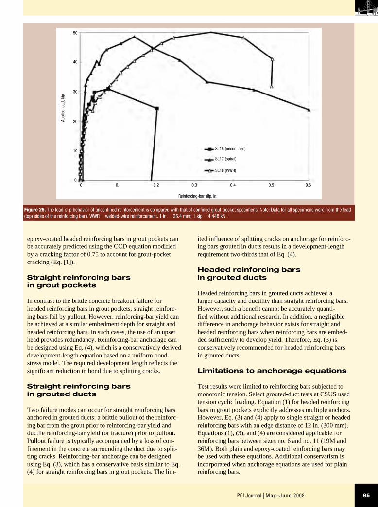
However, a direct comparison of response for confined specimens indicated that the spiral reinforcement confined the pocket more effectively at smaller deformations. The specimen with spiral reinforcement exhibited smaller crack widths and exhibited crack discontinuity at the surface. Figure 25 shows a much softer load-slip response for the specimen confined with welded-wire reinforcement, cor-responding to greater bond deterioration. This implies that larger grout-pocket deformations were required to mobi-lize the welded-wire reinforcement. Due to its rectangular shape, the reinforcement would be expected to require greater deformation before it could provide effective confinement.
Conclusion
The following conclusions are made based on phase 1 ten-sion pullout test results.
Headed reinforcing bars in grout pockets
Two failure modes can occur for headed reinforcing bars in grout pockets: a brittle concrete breakout failure prior to reinforcing-bar yield or a ductile failure characterized by reinforcing-bar yield (or fracture) prior to concrete break-out. The formation of grout-pocket corner cracks reduces the tensile capacity of single and multiple headed reinforc-ing bars in grout pockets compared with reinforcing bars in cast-in-place concrete. Concrete breakout capacity of
Effect of confining reinforcement
Potential beneficial effects of confinement through spiral and welded-wire reinforcement were investigated for grout-pocket connections using two headed reinforcing bars per pocket. Figure 25 compares load-slip behavior of confined specimens with an unconfined specimen. Simi-lar behavior for both confined and unconfined specimens was observed prior to the formation of splitting cracks. However, upon splitting, confining reinforcement helped restrict crack growth and limit crack widths, especially for the specimen using spiral reinforcement. Both confined specimens achieved a capacity that was 50% larger and exhibited reinforcing-bar slip at the surface of the speci-men at least 2.5 times larger than the unconfined case (at the maximum load of the unconfined specimen).
The use of spiral confining reinforcement did not enable the peak load to be fully maintained, but the load dropped off more gradually than the unconfined specimen after the maximum load was reached. As shown in Fig. 26, the load-distribution diagram showed a sudden decrease in head load and corresponding increase in bond between 6 in. (150 mm) and 12 in. (300 mm) at loads larger than 44 kip (200 kN) for specimens using spiral reinforcement or welded-wire reinforcement. This indicated that the spiral and welded-wire reinforcement effectively confined the cracked grout-pocket region, enabling redistribution of forces and significant residual capacity under large defor-mations.
Table 7. Bond strength for straight reinforcing-bar grout-pocket tests
Test ID* Failure mode
BarsAb, in.2
db, in.
hef, in.
h
db
ef fc'
, ksi
fcg'
,*
ksi
Pyield, kip
Pmax, kip
umax,† psi
umax
fcg'
udgn
fcg'
‡
SL13Yield/pullout
1 no. 8 0.79 1.00 12 12.0 5.2 6.9 52 56 1485 0.22 0.20
SL14Yield/pullout
1 no. 8 0.79 1.00 18 18.0 5.1 6.9 52 73 1291 0.19 0.16
DL05 Pullout 2 no. 6 0.44 0.75 9 12.0 5.7 6.3 n.d. 24 1132 0.18 0.16
DL06Yield/pullout
2 no. 6 0.44 0.75 9 12.0 5.8 6.4 27 28 1320 0.21 0.18
Average 5.45 6.63 — — 1307 0.20 0.17
Coefficient of variance 0.06 0.05 — — 0.11 0.08 0.11
* 2 in. grout-cube strength on test day modified by 0.8 factor † Average bond stress, umax = Pmax/(πdbhef) ‡ Based on bond strength at beginning of significant head slip, prior to maximum load Note: DL05 had no data (n.d.) for Pyield because the bar yield was not reached. DL = double bars; SL = single bar; no. 8 = 25M; no. 6 = 19M. 1 in. = 25.4 mm; 1 kip = 4.448 kN; 1 ksi = 6.895 MPa.
95PCI Journal | May–June 2008
ited influence of splitting cracks on anchorage for reinforc-ing bars grouted in ducts results in a development-length requirement two-thirds that of Eq. (4).
Headed reinforcing bars in grouted ducts
Headed reinforcing bars in grouted ducts achieved a larger capacity and ductility than straight reinforcing bars. However, such a benefit cannot be accurately quanti-fied without additional research. In addition, a negligible difference in anchorage behavior exists for straight and headed reinforcing bars when reinforcing bars are embed-ded sufficiently to develop yield. Therefore, Eq. (3) is conservatively recommended for headed reinforcing bars in grouted ducts.
Limitations to anchorage equations
Test results were limited to reinforcing bars subjected to monotonic tension. Select grouted-duct tests at CSUS used tension cyclic loading. Equation (1) for headed reinforcing bars in grout pockets explicitly addresses multiple anchors. However, Eq. (3) and (4) apply to single straight or headed reinforcing bars with an edge distance of 12 in. (300 mm). Equations (1), (3), and (4) are considered applicable for reinforcing bars between sizes no. 6 and no. 11 (19M and 36M). Both plain and epoxy-coated reinforcing bars may be used with these equations. Additional conservatism is incorporated when anchorage equations are used for plain reinforcing bars.
epoxy-coated headed reinforcing bars in grout pockets can be accurately predicted using the CCD equation modified by a cracking factor of 0.75 to account for grout-pocket cracking (Eq. [1]).
Straight reinforcing bars in grout pockets
In contrast to the brittle concrete breakout failure for headed reinforcing bars in grout pockets, straight reinforc-ing bars fail by pullout. However, reinforcing-bar yield can be achieved at a similar embedment depth for straight and headed reinforcing bars. In such cases, the use of an upset head provides redundancy. Reinforcing-bar anchorage can be designed using Eq. (4), which is a conservatively derived development-length equation based on a uniform bond-stress model. The required development length reflects the significant reduction in bond due to splitting cracks.
Straight reinforcing bars in grouted ducts
Two failure modes can occur for straight reinforcing bars anchored in grouted ducts: a brittle pullout of the reinforc-ing bar from the grout prior to reinforcing-bar yield and ductile reinforcing-bar yield (or fracture) prior to pullout. Pullout failure is typically accompanied by a loss of con-finement in the concrete surrounding the duct due to split-ting cracks. Reinforcing-bar anchorage can be designed using Eq. (3), which has a conservative basis similar to Eq. (4) for straight reinforcing bars in grout pockets. The lim-
Figure 25. The load-slip behavior of unconfined reinforcement is compared with that of confined grout-pocket specimens. Note: Data for all specimens were from the lead (top) sides of the reinforcing bars. WWR = welded-wire reinforcement. 1 in. = 25.4 mm; 1 kip = 4.448 kN.
SL15 (unconfined)
SL17 (spiral)
SL18 (WWR)
50
40
30
20
10
00 0.20.1 0.3 0.4 0.5 0.6
Reinforcing-bar slip, in.
Appl
ied
load
, kip

May–June 2008 | PCI Journal96
Confining reinforcement
Spiral and welded-wire reinforcement effectively confine the cracked grout-pocket region, enabling redistribution of forces and exhibiting significant residual capacity under large deformations. Spiral reinforcement confined the pocket more effectively than welded-wire reinforcement at smaller deformations. Larger grout-pocket deformations were required to mobilize the welded-wire reinforcement due to its rectangular shape.
Acknowledgments
This research was conducted as part of TxDOT project 1748, Design and Detailing of a Precast Bent Cap System, under the supervision of John Vogel, Lloyd Wolf, and Rob-ert Sarcinella. The authors gratefully acknowledge many other individuals who contributed, including dissertation committee members for the first author John E. Breen, Sha-ron L. Wood, Ramon L. Carrasquillo, Richard W. Furlong, and Eric B. Becker; the Industry Review Committee of Randy Rogers (chairman) from McCarthy Brothers; Charlie Burnett from W. W. Webber in Houston, Tex.; Paul Guth-rie from Texas Concrete; Fred Heldenfels IV from Helden-fels Enterprises; Carl Thompson from Dalworth Concrete; Roger Welsh from AGC; Robert J. Gulyas from BASF Construction Chemicals Inc.; and many student participants and technical and administrative staff members at Fergu-son Structural Engineering Laboratory at the University of Texas at Austin. In addition, the authors sincerely thank the PCI Journal reviewers for their valuable comments.
Maximum grout compressive strength used in Eq. (3) and (4) should be limited to 6500 psi (45 MPa) and associated concrete strength should be at least 3500 psi. To help pre-vent the grout from being a weak link in the connection, it is recommended that the modified grout-cube strength ex-ceed the compressive strength of the surrounding concrete by at least 1000 psi.11 Equation (3) applies to a reinforcing bar–duct diameter ratio between 0.28 and 0.35. In addition, possible effects of construction variables, such as pocket and duct cleanliness, are not explicitly addressed but may be incorporated into design equations through modifica-tion of the strength-reduction factor. Overhead and inclined grouted-reinforcing-bar applications require special con-sideration for proper grout placement. Brenes et al. address the influence of plastic ducts and offset reinforcing bars for grouted connections.24 Application of equations to bent-cap design will be presented in a future publication.
Grout extension
The addition of coarse aggregate to grout reduced the ef-fects of splitting cracks and resulted in stiffer load-slip re-sponse. However, neat grouts possess significant construc-tability advantages over extended grouts. Grout-pocket specimens using neat grout achieved the same capacity as similar specimens using grout extended with 3/8-in.-diame-ter (9.5 mm) pea gravel.
Figure 26. This graph shows the distribution of reinforcing-bar forces for specimens confined with spiral and welded-wire reinforcement.Note: WWR = welded-wire reinforcement. 1 in. = 25.4 mm; 1 kip = 4.448 kN.
Applied load
SL17 (spiral), 12 in.
SL18 (WWR), 6 in.
SL18 (WWR), 12 in.
50
40
30
20
10
00 205 10 15 25 30 35 40 45 50
Applied load, kip
Rein
forc
ing-
bar f
orce
, kip

97PCI Journal | May–June 2008
Tobolski, M. J., J. I. Restrepo, E. E. Matsumoto, and 10. M. L. Ralls. 2006. Development of Precast Bent Cap Concepts. SSRP Report No. 06/10. La Jolla, CA: University of California, San Diego.
Matsumoto, E. E. 2000. Development of a Precast 11. Bent Cap System. PhD thesis, University of Texas at Austin.
Matsumoto, E. E., M. E. Kreger, M. C. Waggoner, 12. and G. Sumen. 2002. Grouted Connection Tests in the Development of a Precast Bent Cap System. Trans-portation Research Record, 1814: pp. 55–64.
Matsumoto, E. E., M. E. Kreger, M. C. Waggoner, 13. and G. Sumen. 2000. Preliminary Results in the De-velopment of a Precast Bent Cap System. In Proceed-ings of Symposium on High Performance Concrete, pp. 719–730. Orlando, FL: PCI/FHWA/fib (Interna-tional Federation for Structural Concrete).
Headed Reinforcement Corp. 1998. 14. XTENDER. Foun-tain Valley, CA: Headed Reinforcement Corp.
ASTM C939-02. 2002.15. Standard Test Method for Flow of Grout for Preplaced-Aggregate Concrete (Flow Cone Method). V. 04.02. West Conshohocken, PA: American Society for Testing and Materials (ASTM).
ASTM C937-02. 2002. 16. Standard Specification for Grout Fluidifier for Preplaced-Aggregate Concrete. V. 04.02. West Conshohocken, PA: ASTM.
ASTM C938-02. 2002. S17. tandard Practice for Pro-portioning Grout Mixtures for Preplaced-Aggregate Concrete. V. 04.02. West Conshohocken, PA: ASTM.
ASTM C940-98a. 2003. 18. Standard Test Method for Expansion and Bleeding of Freshly Mixed Grouts for Preplaced-Aggregate Concrete in the Laboratory. V. 04.02. West Conshohocken, PA: ASTM.
Fuchs, W., R. Eligehausen, and J. E. Breen. 1995. 19. Concrete Capacity Design (CCD) Approach for Fas-tening to Concrete. ACI Structural Journal, V. 92, No. 1 (January–February): pp. 73–94.
Mislinski, S. M. 2003. Anchorage of Grouted Connec-20. tors for a Precast Bent Cap System in Seismic Regions (Part 2). Masters thesis, California State University, Sacramento, Calif.
Mandawe, J., S. M. Mislinski, and E. E. Matsumoto. 21. 2002. Reinforcement Anchorage in Grouted Duct Connections for a Precast Bent Cap System in Seismic Regions. In Proceedings of PCI/FHWA Concrete Bridge Conference. Nashville, TN: PCI/FHWA.
The findings and opinions expressed in this paper are those of the authors only and do not necessarily represent the views of the sponsoring agency.
References
Freeby, G., M. Hyzak, R. Medlock, K. Ozuna, J. 1. Vogel, and L. Wolf. 2003. Design and Construction of Precast Bent Caps at TxDOT. In Proceedings of 82nd Annual Transportation Research Board Meet-ing. Washington, DC: Transportation Research Board, National Research Council.
Hohmann, D., M. Hyzak, G. Freeby, and L. Wolf. 2. 2003. Prefabricated Bent Caps on the Lake Belton Bridge. In Proceedings of 3rd International Sympo-sium on High Performance Concrete. Orlando, FL: PCI/Federal Highway Administration (FHWA).
LoBouno, Armstrong & Associates, HDR Engineering 3. Inc., and Morales and Shumer Engineers Inc. 1996. Development of Precast Bridge Substructures. Report for Florida Department of Transportation.
Billington, S. L., R. W. Barnes, and J. E. Breen. 1999. 4. A Precast Segmental Substructure System for Standard Bridges. PCI Journal, V. 44, No. 4 (July–August): pp. 56–73.
Holombo, J., M. J. N. Priestley, and F. Seible. 2000. 5. Continuity of Precast Prestressed Spliced-Girder Bridges under Seismic Loads. PCI Journal, V. 45, No. 2 (March–April): pp. 40–63.
Wolf, L. M., and N. K. Friedman. 1994. Redfish Bay 6. and Morris & Cummings Cut: Innovations on Bridge Construction and Durability. Texas Department of Transportation Technical Quarterly, V. 9, No. 2: pp. 1–3.
Wigington, N. 1997. Pierce Elevated Draws Rave 7. Reviews. Texas Department of Transportation News (March): p. 11.
Zendegui, S., W. N. Nickas, E. Scheuermann, and D. 8. Theobald. 2005. Design-Build Replacement Bridge for St. George Island Protects the Environment and En-sures Durability. PCI Journal, V. 50, No. 6 (Novem-ber–December): pp. 56–71.
Tobolski, M. J., E. E. Matsumoto, and J. I. Restrepo. 9. 2006. NCHRP Project 12-74 Precast Bent Cap Sys-tems for Seismic Regions—Background and Progress. In Proceedings of 5th National Seismic Conference on Bridges and Highways. San Francisco, CA: FHWA/Transportation Research Board.

May–June 2008 | PCI Journal98
udgn = design bond strength
umax = average bond strength at the maximum applied load
φ = strength-reduction factor
ΨCR = modification factor to account for grout-pocket-connection cracking
ΨE = modification factor to account for edge distances smaller than 1.5hef
ACI Committee 318. 2005. 22. Building Code Require-ments for Structural Concrete (ACI 318-05) & Commentary (ACI 318R-05). Farmington Hills, MI: American Concrete Institute (ACI).
California Department of Transportation (Caltrans). 23. 2004. Seismic Design Criteria Version 1.4. Sacramen-to, CA: Caltrans.
Brenes, F. J., S. L. Wood, and M. E. Kreger. 2006. 24. Anchorage Requirements for Grouted Vertical-Duct Connectors in Precast Bent Cap Systems. Research report 4176-1. Austin, TX: Center for Transportation Research, University of Texas at Austin.
Notation
AN = projected concrete-failure area of an anchor or group of anchors
ANo = projected concrete-failure area of one anchor when not limited by edge distance or spacing
cmin = smallest of the edge distances that are less than or equal to 1.5hef
db = nominal diameter of reinforcing bar
fc' = specified compressive strength of concrete
f
c1
' = modified compressive strength, accounting for the grout area within the failure surface
fcg' = specified grout compressive strength
fy = specified yield strength of reinforcing bar
hef = embedment depth
ld = development length
n = number of tensioned anchors in a group
P = tensile force in reinforcing bar
Pb = basic concrete breakout strength in tension of a single anchor
Pcbg = nominal concrete breakout strength in tension of a group of anchors
PCCD = load capacity predicted by the concrete-capacity-design method
Pmax = maximum applied load
r = Pearson product

99PCI Journal | May–June 2008
About the authors
Eric E. Matsumoto, PhD, P.E., is an associate professor for the Department of Civil Engineering at California State University, Sacramento.
Mark C. Waggoner, P.E., is a senior associate for Walter P. Moore and Associates Inc. in Austin, Tex.
Michael E. Kreger, PhD, P.E., is a professor for the School of Civil Engineering at Purdue University in West Lafayette, Ind.
John Vogel, P.E., is a supervis-ing bridge design engineer for the Texas Department of Transporta-tion in Houston, Tex.
Lloyd Wolf, P.E., is a design branch manager for the Texas Department of Transportation in Austin, Tex.
Synopsis
This paper summarizes the development of a precast concrete bent-cap system, which can connect precast concrete bent caps to cast-in-place concrete columns or precast concrete trestle piles in nonseismic regions. The primary focus of this paper is the anchorage of reinforc-ing bars connecting the column or pile to the bent cap. Four connection types were explored, including grout pockets, grouted ducts, grouted sleeve couplers, and bolted connections.
Reinforcing-bar-anchorage failure modes and capacities for grouted ducts and grout pockets developed during the first phase of a three-phase test program are pre-sented based on 32 pullout tests of no. 6 to no. 11 (19M to 36M) epoxy-coated reinforcing bars. Anchorage ca-pacity for headed reinforcing bars in grout pockets was found to be accurately determined using the concrete-capacity-design equation reduced by a factor of 0.75 to account for grout-pocket cracking.
Based on a uniform bond-stress model, development-length equations for straight reinforcing bars in grout pockets and straight and headed reinforcing bars in grouted ducts were conservatively established for de-sign. Grout-pocket specimens using neat grout achieved the same capacity as similar specimens using grout extended with pea gravel. Spiral confining reinforce-ment enhanced ductility and capacity more effectively than welded-wire reinforcement. Phase 2 and 3 test results, the design methodology, and a precast concrete construction connection specification will be presented in a future publication.
Keywords
Anchorage, beam-column connection, bent cap, bond, details, grout pocket, grouted duct, grouted reinforcing bar, precast concrete, pullout test, substructure.
Review policy
This paper was reviewed in accordance with the Precast/Prestressed Concrete Institute’s peer-review process.
Reader comments
Please address any reader comments to PCI Journal editor-in-chief Emily Lorenz at [email protected] or Precast/Prestressed Concrete Institute, c/o PCI Journal, 209 W. Jackson Blvd., Suite 500, Chicago, IL 60606. J