Development of a pre-chamber for ultra-lean operation of ...
11
HAL Id: hal-02504571 https://hal.archives-ouvertes.fr/hal-02504571 Submitted on 10 Mar 2020 HAL is a multi-disciplinary open access archive for the deposit and dissemination of sci- entific research documents, whether they are pub- lished or not. The documents may come from teaching and research institutions in France or abroad, or from public or private research centers. L’archive ouverte pluridisciplinaire HAL, est destinée au dépôt et à la diffusion de documents scientifiques de niveau recherche, publiés ou non, émanant des établissements d’enseignement et de recherche français ou étrangers, des laboratoires publics ou privés. Development of a pre-chamber for ultra-lean operation of gasoline engines Knut Habermann, Bastian Morcinkowski, Christoph Müller, Christof Schernus, Tolga Uhlmann To cite this version: Knut Habermann, Bastian Morcinkowski, Christoph Müller, Christof Schernus, Tolga Uhlmann. De- velopment of a pre-chamber for ultra-lean operation of gasoline engines. Proceedings of 8th Transport Research Arena TRA 2020, April 27-30, 2020, Helsinki, Finland, Apr 2020, Helsinki, Finland. hal- 02504571
Transcript of Development of a pre-chamber for ultra-lean operation of ...

HAL Id: hal-02504571https://hal.archives-ouvertes.fr/hal-02504571
Submitted on 10 Mar 2020
HAL is a multi-disciplinary open accessarchive for the deposit and dissemination of sci-entific research documents, whether they are pub-lished or not. The documents may come fromteaching and research institutions in France orabroad, or from public or private research centers.
L’archive ouverte pluridisciplinaire HAL, estdestinée au dépôt et à la diffusion de documentsscientifiques de niveau recherche, publiés ou non,émanant des établissements d’enseignement et derecherche français ou étrangers, des laboratoirespublics ou privés.
Development of a pre-chamber for ultra-lean operationof gasoline engines
Knut Habermann, Bastian Morcinkowski, Christoph Müller, ChristofSchernus, Tolga Uhlmann
To cite this version:Knut Habermann, Bastian Morcinkowski, Christoph Müller, Christof Schernus, Tolga Uhlmann. De-velopment of a pre-chamber for ultra-lean operation of gasoline engines. Proceedings of 8th TransportResearch Arena TRA 2020, April 27-30, 2020, Helsinki, Finland, Apr 2020, Helsinki, Finland. �hal-02504571�

Proceedings of 8th Transport Research Arena TRA 2020, April 27-30, 2020, Helsinki, Finland
Development of a pre-chamber for ultra-lean operation of gasoline
engines
Knut Habermanna*, Bastian Morcinkowskia, Christoph Müllerb, Christof Schernusa,
Tolga Uhlmanna
aFEV Europe GmbH, Neuenhofstrasse 181, 52078 Aachen, Germany bVKA at Aachen University, Forckenbeckstraße 4, 52074 Aachen, Germany
Abstract
Combustion engines in hybridized powertrains continue to require further reductions in fuel consumption and
emissions. Lean operation represents a major step towards increasing gasoline engine efficiency. Here, pre-
chamber jet ignition offers the potential to assure a reliable ignition and combustion process. This paper describes
the development of such a system. Numerical approaches allow for an efficient development process of the pre-
chamber layout. Thus, the pre-chamber geometry is thoroughly optimized with respect to the combustion quality.
Based thereupon, different pre-chamber layouts were experimentally evaluated. Optical investigations serve to
conclude on burn rate and particulate emissions. Having found a specific layout to achieve stable combustion
(COV<1.5%) for lean (λ > 3) operation and specific NOx emissions below 0.1 g/kWh a synthesis of all findings
serves to define the final concept. The resulting combustion system offers high efficiencies in the entire engine
map and thus excellent conditions for further improving the fuel consumption.
Keywords: Gasoline engine; Pre-chamber ignition; Lean burn; Efficiency
* Corresponding author. Tel.: +49-241-5689-532;
E-mail address: [email protected]
Habermann, Müller, Schernus, Uhlmann / TRA2020, Helsinki, Finland, April 27-30, 2020
2
1. Introduction
Pre-chamber jet ignition represents an attractive approach for a lean burn engine concept in hybridized powertrains.
Such system supplies a large quantity of turbulent hot gas to the main combustion chamber to ignite the highly
diluted mixture. Hence, it is one of the space-igniting techniques [Böwing, Bunce, Sens]. It offers the potential to
assure a reliable ignition and a stable combustion process. The development of such systems seeks intense
frontloading by means of simulation and supportive optical investigations during thermodynamic experimental
phase on a single cylinder engine.
The mixture in a pre-chamber can be realized either through scavenging mixture from the main chamber during
the compression stroke (passive pre-chamber) or through additional external fuel feeding (active pre-chamber).
The dosing can be done either by a check valve, commonly used in commercial gas engines, or by a separate
injector. Active pre-chambers can be supplied with either liquid or gaseous fuels which have some advantages
with regard to mixture formation. For the fuel supply to an active pre-chamber there are examples using fuel vapor
[Schumacher], a pre-mixed fuel / air mixture [Böwing, Sens], methane [Böwing] or hydrogen [Lumsden].
2. Methodology
2.1. Charge Motion Development for Ultra Lean Combustion
An engine concept was developed to achieve high efficiencies for extremely lean mixtures. Usually, such concepts
already make use of new approaches at the conventional ignition system. For example, by increasing the stroke-
to-bore ratio, removing compression volume from the flame deck resulting in aerodynamically optimized high
compression ration piston crowns, ports with maximum charge movement and modern DI injection systems.
For the development of such a layout, engineering processes are used which relate the thermodynamic state, the
mixture formation and the flow characteristic from CFD simulations to combustion parameters. At least the
combustion duration should be estimated; an additional prediction of the ignition or stability limits and the
emissions is more accurate. These development tools are already state of the art for engines with conventional
ignition systems like described by Wiese et al.
The main feature of the engine concept discussed in this paper is an active pre-chamber including a spark-plug and
a fuel injector which enables an efficient combustion process in extreme diluted condition.
In the following a pragmatic approach - consisting of existing and newly developed methodologies - will be applied
to support the development of such a combustion system.
2.2. Combustion modeling
A combination of numerical approaches with various levels of detail was used to layout the combustion system of
the engine. 0D models based on multi-zone combustion were used to evaluate pre-chamber geometries with respect
to the operating conditions, their volumes and hole configuration. This model is based on Auer et al. and describes
both thermodynamic systems, the pre- and main combustion chamber, as well as the characteristics resulting from
the turbulent hot ignition jets. The turbulence model of the main combustion chamber takes into account the mass
entering from the pre-chamber, as well as the terms for turbulence by compression, squish effects and dissipation:
d𝑘
d𝑡=
d𝑘compression
d𝑡+
d𝑘squish
d𝑡+
𝐶hole 𝑣hole2
2 𝑚main
d𝑚hole
d𝑡 (1)
The mass transfer is represented by empirical orifice models.
The calculation of the turbulent flame velocity for pre-chamber and main combustion chamber can be determined
according to Peters and considers in addition to thermodynamic and mixture quantities also the turbulence:
𝑠𝑇−𝑠𝐿
𝑣′=
𝑎4𝑏32
2𝑏1Da + √(
𝑎4𝑏32
2𝑏1Da)
2
+ 𝑎4𝑏32Da (2)
For both combustion chambers, the flame front surface is stored map-based depending on the flame sphere
diameter as proposed by Grill et al. Using reactive 3D computational fluid dynamics (CRFD), the spatially resolved
mixture and turbulence distribution in the pre- and main combustion chamber are considered. In order to keep the
computing effort reasonable, a multi-zone combustion model is used, which calculates the reaction kinetics in a
representative phase space.

Habermann, Müller, Schernus, Uhlmann / TRA2020, Helsinki, Finland, April 27-30, 2020
3
The concept of "zoning" and "mapping" according to Babajimopoulos et al., which is available in many
commercial programs, is used for solving heat release and changes in the composition of chemical species:
"Zoning" is used to classify individual cell values into different zones. This phase space is built up for each time
step with the dimensions temperature and air-fuel ratio. The heat release and mixture composition calculated in
each of these zones is again transferred to the CFD cells in the subsequent "mapping".
2.3. Coupled development process
In a first step, promising designs were derived from a wide range of possible chamber parameters using the
presented 0D model. The design in 3D is then realized using the CRFD simulations.
The 3D simulations are based on thermodynamic boundary conditions from the 0D modelling. In turn, the
empirical turbulence modeling in 0D is replaced by resolved turbulence data from CRFD. Usually one iteration is
sufficient to achieve a convergent result.
3. Results
3.1. Simulation
The simulations have shown that the technical realizable design volumes between 1000 mm³ and 1600 mm³ in
combination with 4 or 6 holes should lead to a stable ignition. Figure 1 shows for a small (1080 mm³) and a large
(1611 mm³) chamber volume the initial pre-optimized CRFD designs.
Figure 1 Pre-optimized 4-hole pre-chamber designs mainly based on initial 0D model layout and design boundaries
Considering the inflow, the central point where the flows meet leads to a strong dissipation resulting in high
turbulence levels. The velocity in the upper part of the pre-chamber, where the spark plug is located, decreases
strongly. However, at this point higher flow velocities and turbulence levels would be desirable to support ignition
and early combustion.
Therefore, a detailed optimization was carried out with the following specifications
A vertically offset swirl arrangement of the holes to generate a stable vortex in the chamber which
dissipates mainly through geometric obstacles.
A change in the shape that is more flow-favorable in the lower area and just dissipative in the upper area.

Habermann, Müller, Schernus, Uhlmann / TRA2020, Helsinki, Finland, April 27-30, 2020
4
A rearrangement of the spark plug to ensure a stable deflection of the ignition spark and a high turbulence
level in the ignition gap.
Figure 2 shows the results of this optimized design. The advantages are clearly visible and independent from the
pre-chamber volume. In addition, mixture formation analysis has been incorporated for the final verification of the
pre-chamber. Results can be found in Serrano et al.
Figure 2 Optimized 4-hole pre-chamber designs resulting from 3D CRFD analysis
3.2. Single Cylinder Engine Testing
Based on the optimizations of the pre-chamber layout shown, tests were carried out on a single cylinder engine. A
significant number of different air/fuel ratio sweeps have been performed to understand working principle better
and to identify optimal operating strategy. Engine maps are created by selection the operation points from various
lean-burn investigations for the best efficiency and lowest NOx emissions.
The engine maps shown in Figure 3 and Figure 4 serve, on the one hand, to illustrate the results of an extreme
lean-burn combustion process in terms of efficiency and emissions that can be achieved with the pre-chamber
ignition system. In addition, the characteristic maps can be used to gain further insights into the function and
boundary conditions for the design of an engine architecture.
In order to generate a fuel consumption-optimized characteristic map, the measuring points with the optimum
efficiency for the respective operating point are selected from the lean-burn loops with different natural gas mass
flows. The points selected on the basis of this criterion all show very good combustion stability with low cyclic
fluctuations of the indicated mean pressure (COVimep is for the most part below 1 %), Figure 3. Hence, all operating
points show a clear distance to the lean-burn limit. The resulting efficiency map reaches the optimum of 43.9 % at
n = 2000 rpm and imep = 15 bar. The efficiency is lowered primarily with reduced load and to a minor extent also
with increasing speed.
The selection of the operating points shows a pre-chamber fuel mass fraction decreasing with speed from more
than 10 % at n = 2000 rpm, imep = 15 bar down to 3.4 % at n = 4000 rpm, imep = 16 bar. As the load decreases,
the pre-chamber fuel mass fraction decreases slightly and rises significantly again to very low loads due to a certain
basic pre-chamber enrichment requirement.
The nitrogen oxide (NO) emissions for operating points of maximum efficiency are between 0.17 g/kWh and 0.51
g/kWh. These emissions, which also increase with engine speed, occasionally show islands of differing emission
Habermann, Müller, Schernus, Uhlmann / TRA2020, Helsinki, Finland, April 27-30, 2020
5
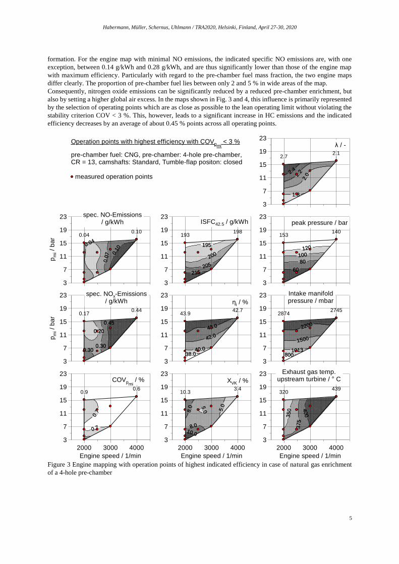
formation. For the engine map with minimal NO emissions, the indicated specific NO emissions are, with one
exception, between 0.14 g/kWh and 0.28 g/kWh, and are thus significantly lower than those of the engine map
with maximum efficiency. Particularly with regard to the pre-chamber fuel mass fraction, the two engine maps
differ clearly. The proportion of pre-chamber fuel lies between only 2 and 5 % in wide areas of the map.
Consequently, nitrogen oxide emissions can be significantly reduced by a reduced pre-chamber enrichment, but
also by setting a higher global air excess. In the maps shown in Fig. 3 and 4, this influence is primarily represented
by the selection of operating points which are as close as possible to the lean operating limit without violating the
stability criterion COV < 3 %. This, however, leads to a significant increase in HC emissions and the indicated
efficiency decreases by an average of about 0.45 % points across all operating points.
Figure 3 Engine mapping with operation points of highest indicated efficiency in case of natural gas enrichment
of a 4-hole pre-chamber
pre-chamber fuel: CNG, pre-chamber: 4-hole pre-chamber, CR = 13, camshafts: Standard, Tumble-flap positon: closed
measured operation points
Operation points with highest efficiency with COVpmi < 3 %
195
200
205
215
198193
195
200
205
215
3
7
11
15
19
23ISFC42.5 / g/kWh
5.0 5
.0
8.0
8.010.0
3.410.3
5.0 5
.0
8.0
8.010.0
3
7
11
15
19
23
Engine speed / 1/min
2000 3000 4000
XVK / %
2200
1500
1013800
27452874
2200
1500
1013800
3
7
11
15
19
23 Intake manifoldpressure / mbar
0.1
0
0.0
7
0.04
0.100.04
0.1
0
0.0
7
0.04
pm
i / b
ar
3
7
11
15
19
23 spec. NO-Emissions/ g/kWh
0.45
0.20
0.300.30
0.440.17
0.45
0.20
0.300.30
pm
i / b
ar
3
7
11
15
19
23 spec. NOx-Emissions/ g/kWh
400
35
0
37
5
439320
400
35
0
37
5
3
7
11
15
19
23
Engine speed / 1/min
2000 3000 4000
Exhaust gas temp.upstream turbine / ° C
120
100
80
60
140153
120
100
80
60
3
7
11
15
19
23peak pressure / bar
2.4
2.2
2.0
1.8
2.12.7
2.4
2.2
2.0
1.8
3
7
11
15
19
23λ / -
43.0
42.0
40.038.0
42.743.9
43.0
42.0
40.038.0
3
7
11
15
19
23ηi / %
0.7
0.7
0.60.9
0.7
0.7
3
7
11
15
19
23
Engine speed / 1/min
2000 3000 4000
COVpmi / %

Habermann, Müller, Schernus, Uhlmann / TRA2020, Helsinki, Finland, April 27-30, 2020
6
Figure 4: Engine mapping with operation points of lowest nitrogen oxide emissions in case of natural gas
enrichment of a 4-hole pre-chamber
Following the discussed lean running limits, the air-fuel ratio for both selection criteria (minimum fuel
consumption or minimum nitrogen oxide emissions) shows a very similar, falling curve towards low loads and
high speeds. This results in an almost linear increase in boost pressure demand and peak pressure with the load. In
order to realize the high loads with a lean combustion relative air-fuel ratio of up to λ = 2.7, an intake manifold
pressure of almost 2900 mbar (absolute) is required. The maximum peak pressure from the two maps averages
500 cycles to 153 bar at n = 2000 rpm and imep = 15 bar. With values ranging between 320 °C and 439 °C or else
between 326 °C and 426 °C, the exhaust gas temperatures before turbine are in a similar range. They increase with
engine speed which on the one hand results from a higher power output, and on the other hand also from a lower
air excess in the selected operating points. From the analogous correlation follows an exhaust gas temperature that
decreases at 2000 rpm with increasing load.
pre-chamber fuel: CNG, pre-chamber: 4-hole pre-chamber, CR = 13, camshafts: Standard, Tumble-flap positon: closed
measured operation points
Operation points with lowest NOx Emissions with COVpmi < 3 %
215
205
200
200197
215
205
200
3
7
11
15
19
23ISFC42.5 / g/kWh
8.0
8.0
5.05.0
3.0
3.0
2.34.9
8.0
8.0
5.05.0
3.0
3.0
3
7
11
15
19
23
Engine speed / 1/min
2000 3000 4000
XVK / %
8001013
1500
2200
28482815
8001013
1500
2200
3
7
11
15
19
23 Intake manifoldpressure / mbar
0.04
0.04
0.0
2
0.07
0.080.03
0.04
0.04
0.0
2
0.07
pm
i / b
ar
3
7
11
15
19
23 spec. NO-Emissions/ g/kWh
0.300.20
0.20
0.10
0.280.14
0.300.20
0.20
0.10
pm
i / b
ar
3
7
11
15
19
23 spec. NOx-Emissions/ g/kWh
375
40
0
350
427327
375
40
0
350
3
7
11
15
19
23
Engine speed / 1/min
2000 3000 4000
Exhaust gas temp.upstream turbine / ° C
60
80
100
120
137147
60
80
100
120
3
7
11
15
19
23peak pressure / bar
1.82.0
2.2
2.4
2.22.6
1.82.0
2.2
2.4
3
7
11
15
19
23λ / -
38.040.0
42.0
43.0
42.442.9
38.040.0
42.0
43.0
3
7
11
15
19
23ηi / %
2.0
1.5
1.11.1
2.0
1.5
3
7
11
15
19
23
Engine speed / 1/min
2000 3000 4000
COVpmi / %

Habermann, Müller, Schernus, Uhlmann / TRA2020, Helsinki, Finland, April 27-30, 2020
7
3.3. Optical Investigations
Figure 5 shows images of the combustion chamber for a further operating point created using an 8 mm endoscope
to visualize the processes in the combustion chamber in addition to the pressure curves and the characteristic values
of the pressure indication. A frame rate of 12 kHz is selected for this observation, whereby a resolution of one
image per degree crank angle is achieved at a speed of 2000 rpm.
Figure 5: Pressures and optical sequences of the pre-chamber ignition system at λ = 2,4, n = 2000 rpm, imep = 15
bar
While at the point of ignition the pressure in the pre-chamber is lower than the pressure in the combustion chamber
due to the throttled inflow into the pre-chamber in the compression phase, the pressure increase in the pre-chamber
generates a positive pressure difference to the combustion chamber due to the fuel conversion from approx. 2.5
deg bTDC. At this point, there are no effects visible in the combustion chamber. In the phase of the maximum
pressure increase at approximately 1 deg CA bTDC, the first formation of turbulent jets into the combustion
chamber can be seen on the images.
In the vicinity of the pressure maximum of the pre-chamber, jets emerging from the jet holes can be very clearly
seen. At this point, the main fuel conversion phase in the pre-chamber is completed. Due to the high pressure
difference, the pre-chamber mass is blown out into the combustion chamber. During this expansion phase of the
pre-chamber, combustion begins in the main combustion chamber. This is shown on the one hand by the
combustion chamber indication which yields 10 % of mass fraction burned according to the heat law. On the other
hand, the differences in density in the combustion chamber become visible on the combustion chamber image at
this point in time.
The resulting fuzziness persists during the combustion and decays at 14 deg CA aTDC. At almost the same time,
the heat law of the combustion chamber indication yields 90% burn rate. In the following burned mixture expands
from the pre-chamber into the main combustion chamber. In this particular operation point, the overflow of burned
mass at 36 deg CA aTDC is clearly visible due to the emitted, luminous particles.

Habermann, Müller, Schernus, Uhlmann / TRA2020, Helsinki, Finland, April 27-30, 2020
8
For further investigations of the combustion behavior measurements with an UV endoscope were carried out.
Using hydrogen enrichment for the pre-chamber ensures that not soot is formed during combustion in the pre-
chamber and thus the turbulent jets exiting the pre-chamber are not containing glowing soot particles. Due to its
different orientation of this endoscope a 6-hole pre-chamber has been used, as the jets are not to targeting directly
to optical access of the cylinder head. The images shown in Figure 6 indicate a similarly good agreement between
the indication indices and optical observations. For example, a transition between the penetration of the turbulent
jets into the combustion chamber and the start of combustion therein with a small inaccuracy is to be associated
with the start of combustion α10. Also, the combustion center correlates quite well with the highest intensity on the
images. At the burning end, identified by the indication as α90, also the intensity of the exposure of the combustion
chamber pictures decreases significantly.
Figure 6: Combustion visualization with UV-transmitting optics
The images also show that the combustion in the main chamber starts along the turbulent jets. However, flame
propagation mainly takes place outside at the cylinder walls. Hence, in contrast to conventional spark plug
operation, the mixture burns from the outside to the center instead of from the center (spark plug) to the outside.
For richer operating points, the combustion process propagating from the outside to the center is more distinct.
The results of Kawabata et al. provide an explanation for this behavior. The mixture dilution in the pre-chamber
is lower due to the influx of mixture from the combustion chamber during compression, and hence, the spray jets
are more intense. They unfold when hitting the combustion chamber walls. This surface enlargement ensures that
the combustion takes-off primarily at the outside and only secondarily along the beams. Firstly, an outer ring of
the combustion is formed. If the spray jets are less intense such as in leaner operation, they do not penetrate so far
into the combustion chamber. Unfolding at the outer cylinder wall is less distinct. The ignition of the mixture along
the spray jets becomes the primary ignition mechanism.
Habermann, Müller, Schernus, Uhlmann / TRA2020, Helsinki, Finland, April 27-30, 2020
9
4. Summary / Conclusion
Pre-chamber jet ignition represents an attractive approach for a lean burn engine concept in hybridized powertrains.
The development of such systems seeks intense frontloading by means of simulation and supportive optical
investigations during thermodynamic experimental phase on a single cylinder engine.
The numerical approaches used for the layout, allow for an efficient development process of the pre-chamber by
combining approaches with various levels of detail. 0D models based on multi-zone combustion are used to
evaluate a broad variety of pre-chamber geometries with respect to the operating conditions, their volumes and
hole configuration. The multi-zone combustion model is based on detailed caloric sub-models taking into account
the mixture state, thermodynamic boundaries and the transition from laminar to turbulent combustion. This
approach is supplemented by the use of reactive 3D computational fluid dynamics, which considers the spatially
resolved mixture and turbulence distribution in the pre- and main combustion chamber. Thus, a detailed
optimization of the pre-chamber geometry with respect to the combustion quality is realized. Based on this
optimization, pre-chambers with different hole number and pattern were realized, tested and evaluated with regard
to lean burn capability, efficiency and emissions. Optical investigations serve to conclude on the burn rate and on
particulate emission. Furthermore, the effects of liquid vs. gaseous pre-chamber fuels as well as of injection
parameters such as e.g. the fuelling ratio of pre-chamber vs. main chamber have been investigated. Having found
specific layouts to achieve stable combustion (COV<1.5%) for homogeneous λ > 3 operation and specific NOx
emissions below 0.1 g/kWh a synthesis of all findings was made to define the final concept as the best compromise
for the required specification. Furthermore, the findings allow to interpret the combustion stability mechanisms at
the lean burn limit and to show options for controlling them. The resulting combustion system with its good lean
burn capability offers a high efficiency in the entire engine map and thus excellent conditions for further improving
the efficiency of electrified powertrains.
Acknowledgements
Project ‘EAGLE’ has received funding from the European Union's Horizon 2020 research and innovation program
under grant agreement No 724084 (https://h2020-eagle.eu).
The authors express their thanks to T. Ottenwälder, C. Kupiek and A. Jeckel
Nomenclature
CC combustion chamber
CA crank angle
COV coefficient of variation (here: of IMEP)
CFD Computational Fluid Dynamics
CR compression ratio
CRFD Computational Reactive Fluid Dynamics
IMEP indicated mean effective pressure
nmot engine speed
NO nitrogen oxide
PC pre-chamber
SOICC start of injection combustion chamber
SOIPC start of injection pre-chamber
mK_VK_Z injected fuel mass into pre-chamber each combustion cycle
αi spark timing
α10 10 % mass fraction burnt
α10 50 % mass fraction burnt
α10 90 % mass fraction burnt
λ relative air-fuel-ratio
k Turbulent kinetic energy
kx Turbulent kinetic energy in geometrical range x
m mass
mx mass in geometrical range x
vhole velocity in pre-chamber hole

Habermann, Müller, Schernus, Uhlmann / TRA2020, Helsinki, Finland, April 27-30, 2020
10
chole discharge coefficient of pre-chamber hole
t Time
sT Turbulent combustion velocity
sL Laminar Combustion Velocity
Da Damköhler Number
v’ Turbulent fluctuation velocity
b1 Model constant for turbulent combustion approximation
b3 Model constant for turbulent combustion approximation
a4 Model constant for turbulent combustion approximation
References
R. Böwing: “Der Einfluß von Zündung und Zylinderinnenströmung auf die Verbrennung in Ottomotoren mit hoher Ladungsverdünnung, Dissertation RWTH Aachen 2000
M. Bunce, H. Blaxill: “Sub-200 g/kWh BSFC on a Light Duty Gasoline Engine”, SAE Technical Paper 2016-01-0709, 2016, doi:10.4271/2016-01-0709
M. Sens, E. Binder, P.-B. Reinicke, M. Rieß, T. Stappenbeck, M. Woebke: „Die Vorkammerzündung und vielversprechende Komplementär-Technologien“ – 27. Aachener Kolloquium 2018
M. Schumacher, M. Wensing: “A Gasoline Fuelled Pre-Chamber Ignition Sys-tem for homogenous Lean Combustion Processes”, SAE Technical Paper 2016-01-2176, 2016, doi:10.4271/2016-01-2176
G. Lumsden, H.C. Watson : “Optimum Control of an S.I. Engine with a λ=5 Capability”, SAE Technical Paper 950689, 1995, doi:10.4271/950689
Y. Kawabata und D. Mori, „Combustion Diagnostics & Improvement of a Pre-chamber Lean-Burn Natural Gas Engine“ in SAE Technical Paper Series, 2004-01-0979
M. Auer, S. Blodig and G. Wachtmeister, “Combustion Modelling of Open Chamber and Pre-Chamber Gas Engines”. 9th Stuttgarter International Symposium, 2009
N. Peters, “Turbulent Combustion (Cambridge Monographs on Mechanics)”. Cambridge University Press, 2000 M. Grill, M. Bargende, “Cylinder Module: Development of a highly-modular zero-dimensional engine process
calculation code”. FVV project no. 869, 2013 A. Babajimopoulos et al., „A fully coupled computational fluid dynamics and multi-zone model with detailed
chemical kinetics for the simulation of premixed charge compression ignition engines“ in International Journal of Engine Research 6, 2005
D. Serrano, J.-M. Zaccardi, C. Müller, C. Libert and K. Habermann, “Ultra-Lean Pre-Chamber Gasoline Engine for Future Hybrid Powertrains” in SAE ICE 2019 (planned)
W. Wiese, S. Pischinger, P. Adomeit and J. Ewald, "Prediction of Combustion Delay and -Duration of Homogeneous Charge Gasoline Engines based on In-Cylinder Flow Simulation" in SAE Technical Paper 2009-01-1796, 2009
![[Lean 101] Introduction to Lean - Preparing a Lean Canvas](https://static.fdocuments.in/doc/165x107/58f160751a28abf1658b4621/lean-101-introduction-to-lean-preparing-a-lean-canvas.jpg)