Development of a porous 3D graphene-PDMS scaffold for ...
26
University of Wollongong Research Online Australian Institute for Innovative Materials - Papers Australian Institute for Innovative Materials 2017 Development of a porous 3D graphene-PDMS scaffold for improved osseointegration Jianfeng Li University of Wollongong, [email protected] Xiao Liu University of Wollongong, [email protected] Jeremy Micah Crook University of Wollongong, [email protected] Gordon G. Wallace University of Wollongong, [email protected] Research Online is the open access institutional repository for the University of Wollongong. For further information contact the UOW Library: [email protected] Publication Details Li, J., Liu, X., Crook, J. M. & Wallace, G. G. (2017). Development of a porous 3D graphene-PDMS scaffold for improved osseointegration. Colloids and Surfaces B: Biointerfaces, 159 386-393.
Transcript of Development of a porous 3D graphene-PDMS scaffold for ...

University of WollongongResearch Online
Australian Institute for Innovative Materials - Papers Australian Institute for Innovative Materials
2017
Development of a porous 3D graphene-PDMSscaffold for improved osseointegrationJianfeng LiUniversity of Wollongong, [email protected]
Xiao LiuUniversity of Wollongong, [email protected]
Jeremy Micah CrookUniversity of Wollongong, [email protected]
Gordon G. WallaceUniversity of Wollongong, [email protected]
Research Online is the open access institutional repository for the University of Wollongong. For further information contact the UOW Library:[email protected]
Publication DetailsLi, J., Liu, X., Crook, J. M. & Wallace, G. G. (2017). Development of a porous 3D graphene-PDMS scaffold for improvedosseointegration. Colloids and Surfaces B: Biointerfaces, 159 386-393.

Development of a porous 3D graphene-PDMS scaffold for improvedosseointegration
AbstractOsseointegration in orthopedic surgery plays an important role for bone implantation success. Traditionaltreatment of implant surface aimed at improved osseointegration has limited capability for its poorperformance in supporting cell growth and proliferation. Polydimethylsiloxane (PDMS) is a widely usedsilicon-based organic polymer material with properties that are useful in cosmetics, domestic applications andmechanical engineering. In addition, the biocompatibility of PDMS, in part due to the high solubility ofoxygen, makes it an ideal material for cell-based implants. Notwithstanding its potential, a property that caninhibit PDMS bioactivity is the high hydrophobicity, limiting its use to date in tissue engineering. Here, wedescribe an efficient approach to produce porous, durable and cytocompatible PDMS-based 3D structures,coated with reduced graphene oxide (RGO). The RGO/PDMS scaffold has good mechanical strength andwith pore sizes ranging from 10 to 600 μm. Importantly, the scaffold is able to support growth anddifferentiation of human adipose stem cells (ADSCs) to an osteogenic cell lineage, indicative of its potential asa transition structure of an osseointegrated implant.
DisciplinesEngineering | Physical Sciences and Mathematics
Publication DetailsLi, J., Liu, X., Crook, J. M. & Wallace, G. G. (2017). Development of a porous 3D graphene-PDMS scaffoldfor improved osseointegration. Colloids and Surfaces B: Biointerfaces, 159 386-393.
This journal article is available at Research Online: http://ro.uow.edu.au/aiimpapers/2746
1
Development of porous 3D graphene-PDMS 1
scaffolds for improved osseointegration 2
Jianfeng Li1, Xiao Liu
1*, Jeremy M. Crook
1,2,3, and Gordon G. Wallace
1* 3
1ARC Centre of Excellence for Electromaterials Science, 4
Intelligent Polymer Research Institute, AIIM Facility, 5
University of Wollongong, NSW 2500, Australia 6
2Illawarra Health and Medical Research Institute, University of Wollongong, Wollongong, 7
New South Wales 2522, Australia 8
3Department of Surgery, St Vincent’s Hospital, The University of Melbourne, Fitzroy, 9
Victoria 3065, Australia 10
* Corresponding author. 11
Tel: +61-2-42213127 12
Fax: +61-2-42213114 13
E-mail address: [email protected]; [email protected] 14
Keywords: Graphene, PDMS, Bone regeneration, Stem cell, Osseointegration 15
16 17 18 19
2
Abstract 1
Osseointegration in orthopedic surgery plays an important role for bone implantation success. 2
Traditional treatment of implant surface aimed at improved osseointegration has limited 3
capability for its poor performance in supporting cell growth and proliferation. 4
Polydimethylsiloxane (PDMS) is a widely used silicon-based organic polymer material with 5
properties that are useful in cosmetics, domestic applications and mechanical engineering. In 6
addition, the biocompatibility of PDMS, in part due to the high solubility of oxygen, makes it 7
an ideal material for cell-based implants. Notwithstanding its potential, a property that can 8
inhibit PDMS bioactivity is the high hydrophobicity, limiting its use to date in tissue 9
engineering. Here, we describe an efficient approach to produce porous, durable and 10
cytocompatible PDMS-based 3D structures, coated with reduced graphene oxide (RGO). The 11
RGO/PDMS scaffold has good mechanical strength and with pore sizes ranging from 10-600 12
μm. Importantly, the scaffold is able to support growth and differentiation of human adipose 13
stem cells (ADSCs) to an osteogenic cell lineage, indicative of its potential as a transition 14
structure of an osseointegrated implant. 15
16
Introduction 17
Orthopedic implants have been widely used to repair bone damage caused by trauma or 18
disease. Metal and its alloys are widely used for implant fabrication due to their mechanical 19
properties, excellent corrosion resistance and biocompatibility [1]. However, metal-based 20
orthopedic implants show limited osseointegration resulting in bone resorption and post-21
implant loosening [2, 3]. Ways to improve the interface between implant surface and 22
3
surrounding tissue have been developed, including increasing surface roughness, chemical 1
surface modification, or coating materials [2, 4-8]. However, since osseointegration largely 2
relies on two-dimensional (2D) structure manipulation, the majority of approaches show poor 3
efficacy. An alternative and perhaps better approach would be to develop a 3D porous 4
scaffold for enhanced osseointegration and post-surgical recovery. 5
As one of the most extensively utilised synthetic materials for biomedical devices and 6
implants, polydimethylsiloxane (PDMS) has been widely used in medicine for over 30 years 7
[9]. A number of valuable bulk properties, including elasticity, chemical and biological 8
inertness, permeability to oxygen, and ease of fabrication make PDMS a promising candidate 9
for long-term interfacial coating for orthopedic implants [10]. To encourage incorporation of 10
newly formed bone through a PDMS scaffold coating, it is necessary to introduce 11
interconnected micro and macro pores. This should lead to stable integration of the 12
orthopedic implant with surrounding tissue [2]. However, notwithstanding its appeal, PDMS 13
scaffolds do not support cell adhesion and proliferation well due to the inherent 14
hydrophobicity and biofouling tendency [11]. It is therefore critical to render PDMS surfaces 15
hydrophilic for their use as cell supporting scaffolds. 16
Graphene has attracted much attention since its rediscovery [12] in 2004, due to its innate 17
strength, ease of isolation, thermal and electrical properties as well as good biocompatibility 18
[13, 14]. Several studies have demonstrated that various graphene based materials, such as 19
graphene coating and stand-alone graphene hydrogel, improve cell adhesion and proliferation 20
[14], and support stem cell differentiation into various lineages, including osteoblasts, 21
neurons, and myocytes [15-17]. In addition, graphene has been approved to support bone 22
regeneration in vivo [18]. Consequently, strategies based on graphene coating have potential 23
for generating PDMS scaffolds with enhanced cytocompatibility. Furthermore, there is a 24

4
growing interest in delivering stem cells with appropriate scaffolds to enhance bone 1
formation in critical-sized bone defects [19, 20]. Human ADSCs represent excellent 2
candidates being accessible for autologous transplantation, and able to be differentiation to 3
osteogenic lineage for bone regeneration [21]. 4
Here, we propose a way to fabricate a porous, durable and cytocompatible interfacial 5
scaffolds via the coating of RGO onto porous PDMS. The fabrication process is simple, 6
scalable and efficient. The structure has applicable mechanical strength with interconnected 7
pores facilitating vascularization and accessibility of nutrients, liquid, and gas for cell 8
support. Moreover, the scaffold supports human ADSC proliferation and differentiation to 9
osteogenic lineage demonstrating the potentially application for interfacial transition material 10
for improved osseointegration. 11
2. Experimental section 12
Materials 13
Natural graphite flakes, sodium nitrate (NaNO3) and sodium chloride (NaCl) were purchased 14
from Sigma-Aldrich (USA). 98% sulfuric acid (H2SO4), potassium permanganate (KMnO4), 15
32% hydrochloric acid (HCl), 30% hydrogen peroxide (H2O2), absolute ethanol (EtOH) and 16
95% n-hexane were purchased from Chem-Supply (Australia). L-ascorbic acid was 17
purchased from BDH Chemicals (Australia). SYLGARD®184 silicone elastomer kit (PDMS) 18
was purchased from Dow Corning (USA) and used as received. 19
Synthesis of soluble RGO 20

5
Graphene oxide (GO) was synthesized by modified Hummers method as previously 1
described [22, 23]. Briefly, 1 g natural graphite flakes was oxidized by mixing with oxidizing 2
agents (50 ml 98% H2SO4, 1 g NaNO3, 6 g KMnO4). The reaction was terminated by addition 3
of 30% H2O2. The resulting mixture was washed with 1 M HCl followed by distilled water. 4
The obtained graphite oxide was exfoliated into GO by 5 hr ultrasonication (Unisonics 5
cleaner, Australia). GO was reduced by 50 mM L-ascorbic acid solution overnight [24]. 6
Impurities in the RGO product were removed by washing with distilled water, followed by 7
centrifugation (Eppendorf 5702 Centrifuge; Germany) until the pH was almost neutral. As-8
synthesized RGO was subsequently dispersed in water to form a stable 1 mg/ml suspension 9
by 1 hr ultrasonication. 10
Synthesis of porous RGO/PDMS structure 11
12
13
14
15
16
Fig. 1. Schematic of the fabrication and use for tissue engineering of porous RGO/PDMS 17
scaffold. 18
As shown in Fig. 1, 30 g NaCl was added into a 90 mm diameter petri dish followed by 19
mixing with 10 ml 70% EtOH. The NaCl solution was heated at 95°C for 30 min with further 20

6
removal of moisture at 60 °C for 10 hr. Base (10 g) and curing (1 g) agents of PDMS were 1
mixed thoroughly and 2.02 ml hexane was used to dilute the PDMS mixture. Then 5.5 g 2
diluted PDMS mixture was combined with 4 °C NaCl scaffold in a petri dish and maintained 3
at 4 °C for 12 hr followed by curing of the PDMS at 60 °C for 5 hr and leaching of sacrificial 4
NaCl scaffold in 50 - 60 °C water for 3 days. Dried porous PDMS scaffold was dipped in 1 5
mg/ml RGO solution and dried at 60 oC for 1 hr, with the process repeated twice more, 6
followed by 2 hr drying. After final drying, the scaffold was cut into a desired shape for 7
further use. 8
Variation of coating times (up to 6 times) of RGO was conducted for optimization. After a 3rd
9
coating of RGO, the conductivity of the RGO/PDMS scaffold reached peak value and the 10
morphology of the coated RGO layer was uniform throughout the whole scaffold (Fig. S1). 11
Therefore, 3 coatings of RGO were deemed optimal and utilized for the subsequent 12
fabrication of RGO/PDMS scaffolds. 13
Scanning electron microscopy 14
The morphology of synthesized RGO and structural features of RGO/PDMS scaffold were 15
characterized by using JEOL JSM-7500FA Scanning Electron Microscope (SEM) and JEOL 16
JSM-6490LA SEM respectively. For characterization of the scaffold with cells, freeze-dried 17
samples were coated with platinum (15 nm) using an Edwards sputter coater and then 18
assessed with the JEOL JSM-6490LA SEM. 19
Porosity analysis 20
7
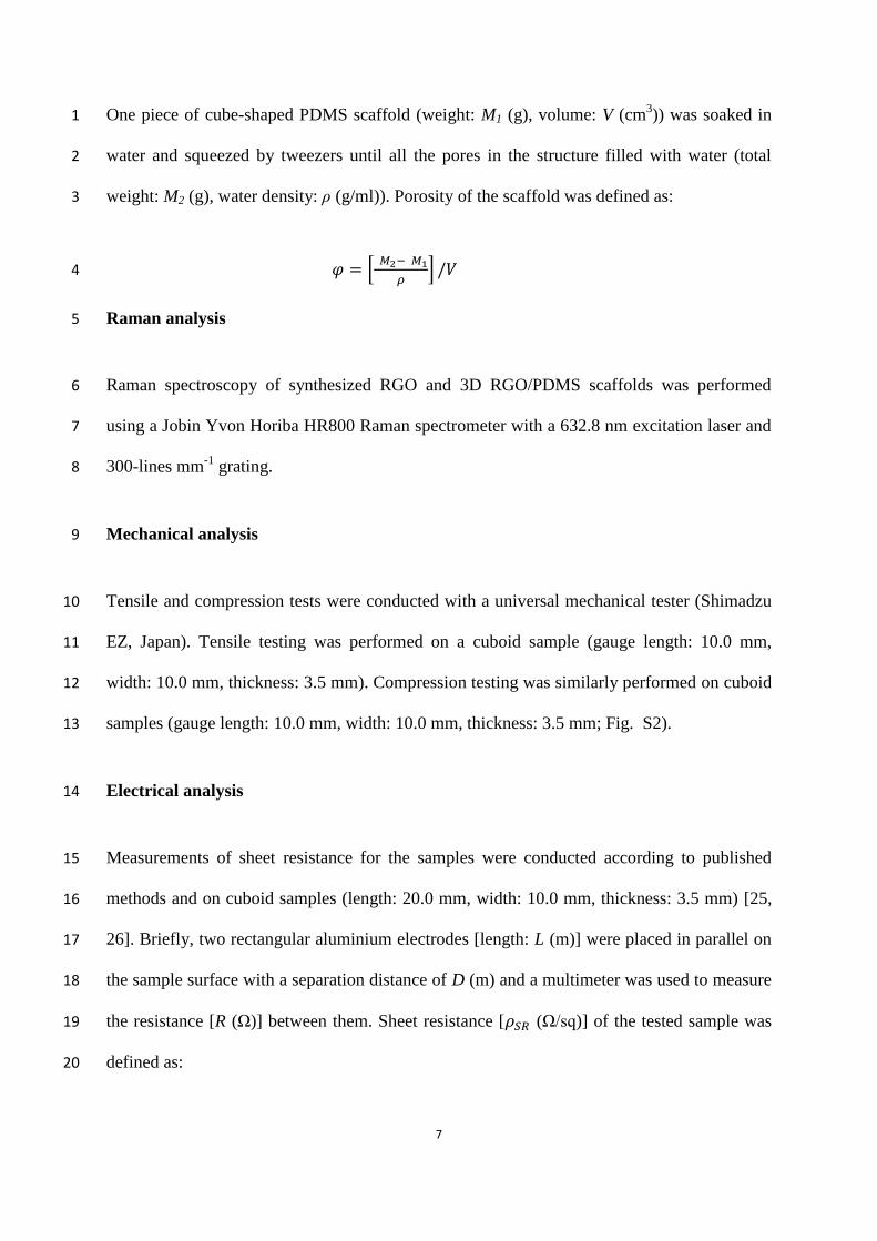
One piece of cube-shaped PDMS scaffold (weight: M1 (g), volume: V (cm3)) was soaked in 1
water and squeezed by tweezers until all the pores in the structure filled with water (total 2
weight: M2 (g), water density: ρ (g/ml)). Porosity of the scaffold was defined as: 3
𝜑 = [ 𝑀2− 𝑀1
𝜌] /𝑉 4
Raman analysis 5
Raman spectroscopy of synthesized RGO and 3D RGO/PDMS scaffolds was performed 6
using a Jobin Yvon Horiba HR800 Raman spectrometer with a 632.8 nm excitation laser and 7
300-lines mm-1
grating. 8
Mechanical analysis 9
Tensile and compression tests were conducted with a universal mechanical tester (Shimadzu 10
EZ, Japan). Tensile testing was performed on a cuboid sample (gauge length: 10.0 mm, 11
width: 10.0 mm, thickness: 3.5 mm). Compression testing was similarly performed on cuboid 12
samples (gauge length: 10.0 mm, width: 10.0 mm, thickness: 3.5 mm; Fig. S2). 13
Electrical analysis 14
Measurements of sheet resistance for the samples were conducted according to published 15
methods and on cuboid samples (length: 20.0 mm, width: 10.0 mm, thickness: 3.5 mm) [25, 16
26]. Briefly, two rectangular aluminium electrodes [length: L (m)] were placed in parallel on 17
the sample surface with a separation distance of D (m) and a multimeter was used to measure 18
the resistance [R (Ω)] between them. Sheet resistance [𝜌𝑆𝑅 (Ω/sq)] of the tested sample was 19
defined as: 20

8
𝜌𝑆𝑅 = 𝑅 ∗ 𝐿/𝐷
ADSC culture 1
Human ADSCs were purchased from Lonza, Australia. Gibco Dulbecco’s Modified Eagle 2
Medium (DMEM), foetal bovine serum (FBS), 100x penicillin-streptomycin, 100x Non-3
Essential Amino Acids Solution (NEAA), basic fibroblast growth factor (bFGF) were 4
obtained from Thermo Fisher (Australia). 5
ADSCs were cultured in DMEM supplemented with 10% FBS, 1% penicillin-streptomycin, 6
1% NEAA and 1ng/ml bFGF in a humidified incubator at 37 °C with 5 % CO2 atmosphere. 7
The initial cell seeding density was 2x10⁴ cells per cm
2. 8
ADSC differentiation 9
Osteogenic differentiation of ADSC was induced by culture medium supplemented with 50 10
μM ascorbic acid, 10 nM dexamethasone and 10 mM β-glycerophosphate [27]. ADSCs were 11
seeded on the top of 2D and 3D samples (Dimensions of 2D rectangular sample: 10.0 mm × 12
10.0 mm, dimensions of 3D cuboid sample: 10.0 mm × 10.0 mm × 3.5 mm) at 5 × 10⁴ cells 13
per scaffold in culture medium for 24 h, followed by differentiation medium. For cell seeding 14
of 3D scaffolds, each scaffold was squeezed several times using tweezers for homogenous 15
cell distribution and loading throughout a construct. Medium was then changed every 2 days 16
for 3 weeks. Samples were subsequently fixed in 3.7 % paraformaldehyde/PBS solution for 17
30 min. After being rinsed in Milli-Q water, the samples were stained with 0.6 % Alizarin 18
Red-S solution at pH 4.2 for 20 min at room temperature followed by extensive washing with 19
water. The stained samples were eluted in water with 20% methanol and 10% acetic acid for 20

9
30 min, and 200 µl eluted solution of each sample was transferred to the well of a 96-well 1
plate, screened with a microplate reader (POLARstar Omega) at 405 nm for absorbance. 2
ADSC proliferation and live/dead cell analyses 3
ADSC proliferation was studied using PrestoBlue (Thermo Fisher, Australia) cell viability 4
reagent in accordance with the manufacturer`s protocol. Cell seeding number for 2D and 3D 5
scaffolds was the same, both were 0.025 million per scaffold. Cell seeding procedure and 6
scaffold dimensions were identical to differentiation samples. Cells were evaluated 1, 3, 5, 7
and 7 days after cell seeding with samples studied in triplicate for each time point using a 8
microplate reader (POLARstar Omega) at 544 nm for fluorescence intensity. Following 9
screening, samples were transferred to basal culture medium for further characterisation. 10
Calcein AM (5 μg/ml; Thermo Fisher, Australia) and propidium iodide (PI; 1 μg/ml; Thermo 11
Fisher, Australia) were used as live and dead cells assay respectively, as per manufacturer’s 12
instructions. Briefly, samples were incubated with Calcein AM and PI at 37 oC for 5 min, 13
followed by a media change. AxioImager microscope (Zeiss, Germany) was used for 14
assessment and image acquisition. 15
Alkaline phosphatase assay 16
ADSCs were seeded onto 2D and 3D scaffolds (dimensions of 2D rectangular sample: 5.0 17
mm × 5.0 mm, dimensions of 3D cuboid sample: 5.0 mm × 5.0 mm × 3.5 mm.) at 10
4 cells 18
per scaffold and bathed with osteogenic differentiation medium. Medium was changed every 19
2 days of cell culture. Following 1, 3, 5, 7 days of differentiation, alkaline phosphatase (AP) 20
activity was evaluated by using an AP activity assay in accordance with the manufacturer’s 21
instructions (Biovision, USA). Briefly, 3D and 2D scaffolds were incubated in 600 µl and 22

10
300 µl Assay Buffer respectively for 1 hr. For each sample, the supernatant of the lysis 1
solution was mixed with 0.5 mM substrate solution for 30 min at 25 °C in a light-proof 2
environment. The formation of fluorometric substrate was measured at Ex/Em = 3
360nm/440nm by using a microplate reader (POLARstar Omega). 4
Statistical analysis 5
All data are expressed as mean ± standard deviation (SD) unless specified. A two-way 6
ANOVA with Bonferroni post hoc test was used for comparison, and a p-value of less than 7
0.05 was considered to be statistically significant. 8
9
3. Results and discussion 10
Material characterisation 11
Fig. 2. Characterization of synthesized RGO. (A, B) SEM images of RGO at low and 12
high magnification, respectively. (C) Raman spectra of RGO film. 13
RGO aqueous dispersion was obtained according to the experimental protocol detailed above, 14
and the dispersion was found to be stable over a period of at least 4 weeks. The RGO 15
dispersion was dried on a glass slide for SEM imaging. Graphene layered structures were 16

11
observed by SEM with the lateral size of graphene being more than 6 μm (Fig. 2A and B). 1
Raman spectrum shows a typical D band (~1330 cm-1
) and G band (~1590 cm-1
) attributed to 2
RGO, whereby D band relates to aromatic structure and G band relates to the degree of 3
graphitization [28]. The ratio of D to G band (ID/IG) was 1.36, indicating a defect induced in 4
the synthesis process comparable with previous reports [28, 29]. 5
6
7
8
9
10
11
Fig. 3. Porosity of PDMS and RGO/PDMS scaffolds. (A, B) Photomicrographs of 12
porous PDMS and RGO/PDMS structures, respectively. (C, D) Low and high 13
magnification SEM images of graphene coated porous PDMS scaffold, respectively. 14
RGO/PDMS scaffolds were mechanically robust and porous structures (Fig. 3A and C) with 15
uniform coatings of RGO (Fig. 3B and D). Pore sizes varied from 10 - 600 μm and the 16
porosity of the structure was calculated to be 63 ± 7%. ID/IG value for 3D RGO/PDMS 17
scaffold was 1.30, which indicates negligible defects induced during the fabrication process. 18
19

12
1
2
3
4
5
6
7
Fig. 4. Mechanical testing of 3D RGO/PDMS scaffold at 10 mm/min under ambient 8
conditions. (A) Mechanical response over time of specimen for 100 times compression. 9
(B) Mechanical response over strain of specimen for 10 times compression (inset: 10
mechanical response over time for 10 times compression). (C) Mechanical response over 11
strain of specimen for tensile testing. 12
Both RGO/PDMS and PDMS scaffolds showed good resistance to compression and tensile 13
stress. The RGO/PDMS scaffold was stable for over 100 × compressions for a strain in 14
excess of 93 % (Fig. 4A and B), whereby the peak stress value was three times higher than 15
that of PDMS scaffold with same compression strain (Fig. S3A). RGO/PDMS scaffold also 16
has a maximum elongation ratio of 0.85-0.90 with tensile strength of 81.05 kPa (Fig. 4C). 17
The peak stress value was 11% higher than that of PDMS scaffold with similar elongation 18
ratio (Fig. S3B). Hence, RGO coating increased the mechanical strength of the PDMS 19
scaffold. The relative lower mechanical strength compared with metal/metal alloy implants 20

13
and bones supports the scaffolds role as a robust cushion layer between implant and 1
surrounding tissue [3]. Importantly, the PDMS substrate was still completely covered with 2
RGO layer after 100 × compressions, indicating strong and durable absorption of RGO on the 3
PDMS substrate. 4
Electrical sheet resistance of the RGO/PDMS scaffold was about 300 kΩ/sq, which may have 5
resulted from the mild reduction environment for RGO, complicated inner porous 6
architecture of the 3D PDMS substrate, and high contact resistance between graphene layers 7
[30, 31]. 8
ADSC culture and differentiation 9
Fig. 5. (A, B) Fluorescence microscope images of live (Calcein AM; green), and dead 10
(propidium iodide; red) ADSCs cultured on porous PDMS and RGO/PDMS structures, 11

14
respectively following 10 days culture. (C) SEM images of ADSCs on RGO/PDMS 1
scaffold surface, and (D) inside the scaffold after less than 24 hr culture. Cells are 2
indicated by yellow arrows while filopodia are circled red. 3
The cytocompatibility of PDMS and RGO/PDMS scaffolds was initially investigated by 4
assessing ADSC viability. Calcein-AM and propidium iodide staining indicated high cell 5
viability following 10 days culture on PDMS and RGO/PDMS scaffolds (Fig. 5A and B). 6
Cytocompatibility of the RGO/PDMS scaffolds is consistent with previous reports of 7
graphene cell support [32, 33]. Cell adhesion was indicated by an abundance of filopodia 8
across the surface and into pores of RGO/PDMS compared to PDMS scaffolds (Fig. 5C and 9
D). 10
11
12
13
14
15
Fig. 6. Average percentage increase of fluorescence intensity (relative to Day 1 average 16
value of 3D RGO/PDMS samples) over time as an indicator of cell proliferation for cells 17
on different 3D scaffolds and 2D culture (control). Mean ± standard deviation, n=3, 18
*p<0.05. 19

15
RGO/PDMS film was fabricated according to a reported method [34] and used to compare 1
cell proliferation for 2D planar cell culture verses the 3D scaffolds. As shown in Fig. 6, 3D 2
scaffolds enhanced cell proliferation between days 3 and 5 of culture, with the rate of 3
increase diminishing rapidly thereafter for 3D PDMS but more slowly for 3D RGO/PDMS. 4
Cell numbers for days 5 and 7 were significantly higher than days 1 and 3 (P<0.05; Fig. 6). 5
Overall, these data demonstrate that 3D RGO/PDMS scaffolds are biocompatible and able to 6
support ADSC growth. The efficacy of 3D RGO/PDMS may be due to a combination of 3D 7
culture more closely resembling the natural niche and mildly reduced graphene oxide being 8
relatively hydrophilic [35]. 9
10
11
12
13
14
15
Fig. 7. Alizarin Red staining of calcium deposition for ADSCs differentiated for 3 weeks 16
on (A) RGO/PDMS porous scaffold and (B) PDMS scaffold in osteogenic induction 17
medium. (C) Quantification of calcium deposition using Alizarin Red S staining. Mean ± 18
standard deviation, n=3, *p<0.05. 19
16
Higher calcium deposition was measured for cells differentiated for 3 weeks on 3D 1
RGO/PDMS scaffold, with low to negligible levels expressed by cells on 3D PDMS, 2D 2
RGO/PDMS and negative controls (Fig. 7A, B and C). For differentiation samples in 3
osteogenic medium, calcium deposition on 3D RGO/PDMS scaffold was significantly higher 4
than 3D PDMS and 2D RGO/PDMS (P<0.05; Fig. 7 C). Samples cultured in cell osteogenic 5
medium have significantly higher calcium deposition compared to cell growth medium 6
(P<0.05; Fig. 7 C). 3D RGO/PDMS scaffold was able to facilitate stem cell induction to 7
osteogenic lineage without additional chemical inducers, consistent with previous reports of 8
graphene and 3D biomaterial scaffolds being conducive to bone engineering [36, 37]. 9
Presently, the higher calcium content of 3D RGO/PDMS may be due to the synergistic effect 10
of graphene and 3D culture supporting osteogenic differentiation. Importantly, after 3 weeks 11
of differentiation, RGO/PDMS scaffolds remained intact and without deformation, which is 12
necessary for longer-term cell support and tissue formation in vitro or in vivo [38]. Scaffolds 13
developed here were more durable than previously reported biodegradable porous scaffolds 14
used for osseointegration [2]. 15
16
17
18
19
20

17
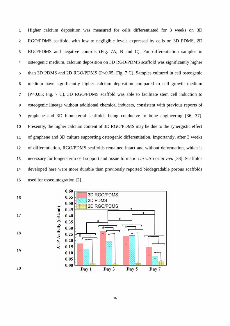
Fig. 8. Upregulation of the AP activity of ADSCs in the 3D RGO/PDMS, 3D PDMS and 1
2D RGO/PDMS for 1, 3, 5, 7 days. Mean ± standard deviation, n=3, *p<0.05. 2
Expression of early osteogenic differentiation cell marker AP was significantly higher for 3D 3
scaffolds than 2D RGO/PDMS film, with the 3D RGO/PDMS associated with the highest AP 4
expression compared to 3D PDMS scaffold (Fig. 8). Upregulation of AP peaked at Day 3 for 5
3D RGO/PDMS scaffold, and day 5 for 3D PDMS scaffold. The peak value of AP expression 6
for 3D RGO/PDMS scaffold was 0.13 fold and 2.1 fold higher than 3D PDMS and 2D 7
RGO/PDMS respectively. Again, our findings are consistent with previous reports of RGO 8
and 3D cell culture being beneficial to osteogenic differentiation of ADSC [39, 40]. 9
10
Conclusion 11
We have developed a scalable, simple and efficient method of fabricating durable, 12
biocompatible, porous RGO/PDMS scaffolds. The approach includes the use of salt porogen 13
and subsequent dip-coating methods. The scaffold was highly porous while being 14
mechanically robust. Moreover, we have demonstrated scaffold cytocompatability, extending 15
to ADSC culture and subsequent osteogenic differentiation. Taking the conductivity of 3D 16
RGO/PDMS into consideration, there is the potential to electrically stimulate cells via the 17
scaffold. By enabling 3D support of ADSC culture and differentiation within a mechanically 18
robust and flexible structure, the scaffold has the potential to be used as a transition layer for 19
improved osseointegration in orthopedic surgery. In addition, it may be adapted for synthesis 20
of various other tissue types in vitro and in vivo for both research and clinical use. 21
Acknowledgements 22
18
The authors wish to acknowledge funding from the Australian Research Council (ARC) 1
Centre of Excellence Scheme (CE140100012), the use of facilities at the University of 2
Wollongong Electron Microscopy Centre, support of the Australian National Fabrication 3
Facility (ANFF)—Materials Node for provision of equipment. Prof. Gordon G. Wallace 4
acknowledges the support of the ARC through an ARC Laureate Fellowship (FL110100196). 5
The authors would also like to thank Assoc. Prof. Chee O. Too and Dr. Kerry Gilmore for 6
their valuable comments on the manuscript. 7
References 8
[1] H. Matsuno, A. Yokoyama, F. Watari, M. Uo, T. Kawasaki, Biocompatibility and 9
osteogenesis of refractory metal implants, titanium, hafnium, niobium, tantalum and rhenium, 10
Biomaterials. 22 (11) (2001) 1253-1262. 11
[2] S. Soumya, P.R. Sreerekha, D. Menon, V.S. Nair, K.P. Chennazhi, Generation of a 12
biomimetic 3D microporous nano-fibrous scaffold on titanium surfaces for better 13
osteointegration of orthopedic implants, J. Mater. Chem. 22 (2012) 1904-1915. 14
[3] M. Khodaei, A. Valanezhad, I. Watanabe, R. Yousefi, Surface and mechanical properties 15
of modified porous titanium scaffold, Surf. Coat. Technol. 315 (2017) 61-66. 16
[4] H.W. He, M.L. Liu, Z.L. Zhu, M.Z. Yang, Q.L. Li, Z.Q. Chen, Influence of surface 17
morphology of cpTi on the adsorption and attachment of collagen/chitosan, Appl. Surf. Sci. 18
255 (2) (2008) 509-511. 19
[5] T. Lu, J. Wen, S. Qian, H. Cao, C. Ning, X. Pan, X. Jiang, X. Liu, P.K. Chu, Enhanced 20
osteointegration on tantalum-implanted polyetheretherketone surface with bone-like elastic 21
modulus, Biomaterials. 51 (2015) 173-183. 22
[6] X.Y. Ma, Y.F. Feng, Z.S. Ma, X. Li, J. Wang, L. Wang, W. Lei, The promotion of 23
osteointegration under diabetic conditions using chitosan/hydroxyapatite composite coating 24
on porous titanium surfaces, Biomaterials. 35 (2014) 7259-7270. 25
19
[7] V.V. Rani, L. Vinoth-Kumar, V.C. Anitha, K. Manzoor, M. Deepthy, V.N. Shantikumar, 1
Osteointegration of titanium implant is sensitive to specific nanostructure morphology, Acta. 2
Biomater. 8 (5) (2012) 1976-1989. 3
[8] X. Li, T. Chen, J. Hu, S. Li, Q. Zou, Y. Li, N. Jiang, H. Li, J. Li, Modified surface 4
morphology of a novel Ti–24Nb–4Zr–7.9Sn titanium alloy via anodic oxidation for enhanced 5
interfacial biocompatibility and osseointegration, Colloids Surf. B: Biointerf. 144 (2016) 6
265-275. 7
[9] M.C. Bélanger, Y. Marois, Hemocompatibility, biocompatibility, inflammatory and in 8
vivo studies of primary reference materials low-density polyethylene and 9
polydimethylsiloxane: A review, J. Biomed. Mater. Res. 58 (2001) 467-477. 10
[10] W. Zhang, Y.S. Zhang, S.M. Bakht, J. Aleman, S.R. Shin, K. Yue, M. Sica, J. Ribas, M. 11
Duchamp, J. Ju, R.B. Sadeghian, D. Kim, M.R. Dokmeci, A. Atala, A. Khademhosseini, 12
Elastomeric free-form blood vessels for interconnecting organs on chip systems, Lab. Chip. 13
16 (2016) 1579-1586. 14
[11] Y.J. Chuah, Y.T. Koh, K. Lim, N.V. Menon, Y. Wu, Y. Kang, Simple surface 15
engineering of polydimethylsiloxane with polydopamine for stabilized mesenchymal stem 16
cell adhesion and multipotency, Sci. Rep. 5 (2015) 18162. 17
[12] A.K. Geim, Graphene: status and prospects, Science. 324 (2009) 1530-1534. 18
[13] A.T. Ezhil Vilian, M. Rajkumar, S.M. Chen, In situ electrochemical synthesis of highly 19
loaded zirconium nanoparticles decorated reduced graphene oxide for the selective 20
determination of dopamine and paracetamol in presence of ascorbic acid, Colloids Surf. B: 21
Biointerf. 115 (2014) 295-301. 22
[14] A.M. Pinto, I.C. Goncalves, F.D. Magalhaes, Graphene-based materials 23
biocompatibility: a review, Colloids Surf. B: Biointerf. 111 (2013) 188-202. 24
[15] N. Dubey, R. Bentini, I. Islam, T. Cao, A.H. Castro Neto, V. Rosa, Graphene: a versatile 25
carbon-based material for bone tissue engineering, Stem Cells Int. 2015 (2015) 12. 26

20
[16] Y.C. Kuo, C.C. Wang, Guided differentiation of induced pluripotent stem cells into 1
neuronal lineage in alginate–chitosan–gelatin hydrogels with surface neuron growth factor, 2
Colloids Surf. B: Biointerf. 104 (2013) 194-199. 3
[17] Y. Talukdar, J.T. Rashkow, G. Lalwani, S. Kanakia, B. Sitharaman, The effects of 4
graphene nanostructures on mesenchymal stem cells, Biomaterials. 35 (18) (2014) 4863-5
4877. 6
[18] E. Silva, L.M.R.d. Vasconcellos, B.V.M. Rodrigues, D.M. dos Santos, S.P. Campana-7
Filho, F.R. Marciano, T.J. Webster, PDLLA honeycomb-like scaffolds with a high loading of 8
superhydrophilic graphene/multi-walled carbon nanotubes promote osteoblast in vitro 9
functions and guided in vivo bone regeneration, Mater. Sci. Eng. C. 73 (2017) 31-39. 10
[19] D. Marolt, M. Knezevic, G. Vunjak-Novakovic, Bone tissue engineering with human 11
stem cells, Stem Cell Res. Ther. 1 (2010) 1-10. 12
[20] P. Rosset, F. Deschaseaux, P. Layrolle, Cell therapy for bone repair, Orthop. 13
Traumatol. Surg. Res. 100 (1) (2014) S107-S112. 14
[21] R. Ravichandran, J.R. Venugopal, S. Sundarrajan, S. Mukherjee, S. Ramakrishna, 15
Precipitation of nanohydroxyapatite on PLLA/PBLG/Collagen nanofibrous structures for the 16
differentiation of adipose derived stem cells to osteogenic lineage, Biomaterials. 33 (3) 17
(2012) 846-855. 18
[22] W.S. Hummers, R.E. Offeman, Preparation of graphitic oxide, J. Am. Chem. Soc. 80 19
(6) (1958) 1339-1339. 20
[23] B. Paulchamy, G. Arthi, B.D. Lignesh, A simple approach to stepwise synthesis of 21
graphene oxide nanomaterial, J. Nanomed. Nanotechnol. 6 (1) (2015) 1000253. 22
[24] J. Zhang, H. Yang, G. Shen, P. Cheng, J. Zhang, S. Guo, Reduction of graphene oxide 23
vial-ascorbic acid, Chem. Commun. 46 (2010) 1112-1114. 24

21
[25] P. Petersen, R. Helmer, M. Pate, J. Eichhoff, Electronic textile resistor design and fabric 1
resistivity characterization, Text. Res. J. 81 (13) (2011) 1395-1404. 2
[26] C. Zhao, K.W. Shu, C.Y. Wang, S. Gambhir, G.G. Wallace, Reduced graphene oxide 3
and polypyrrole/reduced graphene oxide composite coated stretchable fabric electrodes for 4
supercapacitor application, Electrochim. Acta. 172 (2015) 12-19. 5
[27] L. Kyllönen, S. Haimi, B. Mannerström, H. Huhtala, K.M. Rajala, H. Skottman, G.K. 6
Sándor, S. Miettinen, Effects of different serum conditions on osteogenic differentiation of 7
human adipose stem cells in vitro, Stem Cell Res. Ther. 4 (2013) 1-15. 8
[28] X. Gao, X. Tang, Effective reduction of graphene oxide thin films by a fluorinating 9
agent: Diethylaminosulfur trifluoride, Carbon. 76 (2014) 133-140. 10
[29] P. Wang, Z.G. Liu, X. Chen, F.L. Meng, J.H. Liu, X.J. Huang, UV irradiation synthesis 11
of an Au-graphene nanocomposite with enhanced electrochemical sensing properties, J. 12
Mater. Chem. A. 1 (2013) 9189-9195. 13
[30] C. Punckt, F. Muckel, S. Wolff, I.A. Aksay, C.A. Chavarin, G. Bacher, W. Mertin, The 14
effect of degree of reduction on the electrical properties of functionalized graphene sheets, 15
Appl. Phys. Lett. 102 (2) (2013) 023114. 16
[31] Y. Xu, C. Cheng, S..C Du, J.Y. Yang, B. Yu, J. Luo, W.Y. Yin, E.P. Li, S.R Dong, P.D. 17
Ye, X.F. Duan, Contacts between two- and three-dimensional materials: Ohmic, Schottky, 18
and p-n heterojunctions. ACS Nano. 10 (5) (2016) 4895-4919. 19
[32] N. Li, Q. Zhang, S. Gao, Q. Song, R. Huang, L. Wang, L.W. Liu, J.W. Dai, M.L. Tang, 20
G.S. Cheng, Three-dimensional graphene foam as a biocompatible and conductive scaffold 21
for neural stem cells, Sci. Rep. 3 (2013) 1604. 22
[33] T.H. Kim, S. Shah, L. Yang, P.T. Yin, M.K. Hossain, B. Conley, J.W. Choi, K.B. Lee, 23
Controlling differentiation of adipose-derived stem cells using combinatorial graphene 24
hybrid-pattern arrays, ACS Nano. 9 (4) 2015 3780-3790. 25

22
[34] J. Li, E.C. Lee, Carbon nanotube/polymer composite electrodes for flexible, attachable 1
electrochemical DNA sensors, Biosens. Bioelectron. 71 (2015) 414-419. 2
[35] J. Sun, Y. Deng, J. Li, G. Wang, P. He, S. Tian, X. Bu, Z. Di, S. Yang, G. Ding, X. Xie, 3
A new graphene derivative: hydroxylated graphene with excellent biocompatibility, ACS 4
Appl. Mater. Interfaces. 8 (16) (2016) 10226-10233. 5
[36] S.W. Crowder, D. Prasai, R. Rath, D.A. Balikov, H. Bae, K.I. Bolotin, H.J. Sung, Three-6
dimensional graphene foams promote osteogenic differentiation of human mesenchymal stem 7
cells, Nanoscale. 5 (2013) 4171-4176. 8
[37] S. Rumiński, B. Ostrowska, J. Jaroszewicz, T. Skirecki, K. Włodarski, W. 9
Święszkowski, M. Lewandowska-Szumieł, Three-dimensional printed polycaprolactone-10
based scaffolds provide an advantageous environment for osteogenic differentiation of human 11
adipose-derived stem cells, J. Tissue Eng. Regen. Med. (2016) (accepted manuscript) 12
10.1002/term.2310. 13
[38] P.S. Li, I.L. Lee, W.L. Yu, J.S. Sun, W.N. Jane, H.H. Shen, A Novel Albumin-Based 14
Tissue Scaffold for Autogenic Tissue Engineering Applications, Sci. Rep. 4 (2014) 5600. 15
[39] J.H. Lee, Y.C. Shin, S.M. Lee, O.S. Jin, S.H. Kang, S.W. Hong, C.M. Jeong, J.B. Huh, 16
D.W. Han, Enhanced Osteogenesis by Reduced Graphene Oxide/Hydroxyapatite 17
Nanocomposites, Sci Rep. 5 (2015) 18833. 18
[40] A. Mata, E.J. Kim, C.A Boehm, A.J. Fleischman, G.F. Muschler, S. Roy, A three-19
dimensional scaffold with precise micro-architecture and surface micro-textures, 20
Biomaterials. 30 (27) (2009) 4610-4617. 21
22
23
24

23
Supporting information 1
2
3
Fig. S1. After 3 times coating, RGO was uniformly deposited throughout the whole 4
scaffold. 5
6
7
8
9
Fig. S2. Mechanical testing system setups for (A) tensile test; (B) compression test. 10
11

24
Fig. S3. Mechanical testing of pristine 3D PDMS scaffold at 10 mm/min under ambient 1
conditions. (A) Mechanical response over time of specimen for 100 times cyclic 2
compression. (B) Mechanical response over strain of specimen for tensile testing. 3
4
5
6
7
8
9
10
11
12
13


![A Review of Imaging Techniques Compatible with Three ... · Reinnervate and LGC Standards [1]. Alvetex®Scaffold is a 200μm thick highly porous, inert polystyrene scaffold that provides](https://static.fdocuments.in/doc/165x107/5fd5ea3022d7b864a37a9fa8/a-review-of-imaging-techniques-compatible-with-three-reinnervate-and-lgc-standards.jpg)