Development of a Physical Prototyping Lab at Chalmers ... · Prototyping Lab at Chalmers University...
38
Development of a Physical Prototyping Lab at Chalmers University of Technology September 27, 2001 Johan Malmqvist Martin Distner
-
Upload
doankhuong -
Category
Documents
-
view
216 -
download
0
Transcript of Development of a Physical Prototyping Lab at Chalmers ... · Prototyping Lab at Chalmers University...

Development of a Physical Prototyping Lab at
Chalmers University of Technology
September 27, 2001
Johan Malmqvist Martin Distner

2
Abstract In a coordinated effort Chalmers University of Technology (Chalmers), the Royal Institute of Technology (KTH), Linköping University (LiU) and Massachusetts Institute of Technology (MIT) are creating an educational initiative that will have fundamental, long-lasting institutional impact at our universities. A large part of this new model for engineering education is focused on creating an infrastructure for enabling an extensive use of hands-on education. For this purpose Chalmers has set out to develop a product realization lab, this lab will consist of two basic facilities:
• The IDE studio which aims at supporting project teams working with virtual prototypes.
• A physical prototyping lab that enables students to implement and operate their own designs.
This lab will be a fundamental resource used throughout the ME education and the IDE education. The lab will also be used by the Automation Engineering program, in particular the 4th year Mechatronics project course.
The courses using the lab will span from 1st to 4th grade and include specializations and compulsory courses. The compulsory courses are especially important for students who normally would not choose this type of course in a specialization. The activities in the lab will vary from very simple tasks of a few hours to multi semester projects and a mix of simple and advanced machinery is needed.
The work to design this physical prototyping lab has been done in cooperation with a group of about 20 faculty members that are potential users. The group has met every three weeks to discuss issues and advancement of the project. This has resulted in a lab concept that fulfills the requirement specification of the faculty group and makes efficient use of the resources available. The development and planning of the prototyping lab is described in this report.

3
Contents
Abstract ..........................................................................................................................2
Contents .........................................................................................................................3
Preface............................................................................................................................5
Introduction....................................................................................................................6
Use scenarios including curriculum to lab mapping......................................................7
Operational modes .....................................................................................................7
Examples of use .........................................................................................................8
Curriculum to lab mapping ........................................................................................9
Requirement specification ...........................................................................................10
Lab concepts ................................................................................................................11
Concept #1 ...............................................................................................................11
Concept #2 ...............................................................................................................11
Concept #3 ...............................................................................................................12
Concept #4 ...............................................................................................................12
Comparison of primary parameters for concepts.....................................................13
Lab concept evaluation and select ...............................................................................14
Refinement of selected concept ...................................................................................15
Lab development..........................................................................................................16
Conclusions and recommendations for future work ....................................................17
Appendix A..................................................................................................................18
Curriculum to lab mode mapping ............................................................................18
Curriculum to lab demand .......................................................................................21
Appendix B ..................................................................................................................22
Detailed requirement specification. .........................................................................22
Appendix C ..................................................................................................................27
Blueprint for workshop area, concept 1. ..................................................................27
Blueprint for workshop area, concept 2. ..................................................................28
Blueprint for workshop area, concept 3. ..................................................................29
Blueprint for electronics area, concept 1,2 and 3.....................................................30

4
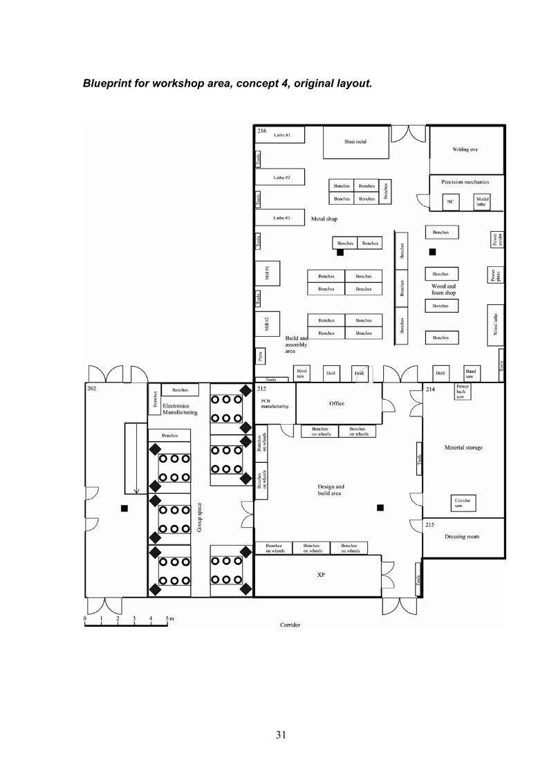
Blueprint for workshop area, concept 4, original layout. ........................................31
Appendix D..................................................................................................................32
Blueprint for workshop area, concept 4, revised layout. .........................................32
Detailed specification...............................................................................................33
3D-models of the revised concept 4.........................................................................36

5
Preface The work to develop a physical prototyping lab at Chalmers is a part of a larger project, which intends to improve the engineering education within several areas. This project is a joint effort from The Royal Institute of Technology (KTH), Linköping University (LiU), Massachusetts Institute of Technology (MIT) and Chalmers. The theme for the project is CDIO, Conception-Design-Implementation-Operation.
The purpose of the physical prototyping lab is to support one of the most important aspects of the CDIO pedagogical strategy, the use of hands-on education. The physical prototyping lab is one of several facilities together creating the infrastructure to realize this new pedagogical strategy.
This report describes the extensive work to develop the physical prototype lab, data for the lab and how the lab will evolve for the next couple of years.
Martin Distner composed this report on the commission of Professor Johan Malmqvist.
6
Introduction For the last 20 years the focus of the engineering education has been on theoretical knowledge within science, design and technology. This has resulted in an education where engineers fresh out of the technical universities are very capable in the theoretical level but does not have the deep understanding and intuitive feel of the fundamentals. The skills to implement and operate actual designs have not been stressed either.
To change this negative trend Chalmers University of Technology (Chalmers), the Royal Institute of Technology (KTH), Linköping University (LiU) and Massachusetts Institute of Technology (MIT) works together in a joint effort to create a new educational model. A large part of this new model for engineering education is focused on creating an infrastructure for enabling an extensive use of hands-on education. For this purpose Chalmers has set out to develop a product realization lab, this lab will consist of two basic facilities:
• The IDE studio which aims at supporting project teams working with virtual prototypes.
• A physical prototyping lab that enables students to implement and operate their designs.
The physical prototyping lab will be a facility where students can realize their paper designs. Manufacture and assemble designs ranging from very simple models to more sophisticated, near production quality models spanning mechanics, electronics and software and in some cases all three in the same project. Physical modeling is essential for understanding manufacturing constraint and for detecting unanticipated phenomena, these qualities are unattainable in virtual models.
The courses using the lab will span from 1st to 4th grade and include specializations and compulsory courses. The compulsory courses are especially important for students who normally would not choose this type of course in a specialization. These students are possibly the students that need the design and build experience the most. The activities in the lab will vary from very simple tasks of a few hours to multi semester projects and a mix of simple and advanced machinery is needed.
To build a base for the work with the physical prototyping lab, interviews were made with faculty at all departments of the School of Mechanical and Vehicular Engineering. At these interviews the faculty members were introduced to the idea of utilizing Implementation and Operation in their courses. They were also invited to join a reference-group (approximately 20 people) that has worked closely with the authors to realize the physical prototyping lab. This group of people has met approximately every three weeks to discuss the advancement of the plans and decide on issues concerning the project.

7
Use scenarios including curriculum to lab mapping The lab is intended to be used in undergraduate courses and in capstone courses. Design-build-test projects already exists in capstone courses but it is intended that this will be introduced in at least one first year course, Introduction to Mechanical Engineering, and two second year courses, Machine Elements and Manufacturing Technology. Therefore the use of the lab will vary from very simple one-week tasks to multiple semester projects.
Operational modes
The different types of activities in the lab are defined in 7 operational modes. These modes cover activities from simple tasks to long term projects, extra curricular projects and tinker sessions.
Basic CDIO Mode
The Basic CDIO Mode represents programs were the use of the physical prototyping lab is an addition to a conventional course as a mean to test and verify paper designs and the work behind these. The team or group (usually 2-4 students) design the product and then manufacture it or parts of it. This hands-on-experience will help the students get that extra grip of the subject that is necessary to learn how to apply and make the full use of the theoretical knowledge they have acquired during the earlier part of the course.
Large Systems Mode
The Large System Mode represents programs that are very design intensive and team oriented, requiring a certain amount of dedicated space for doing the design work and systems prototyping for periods of time ranging from a semester to a year. The definition of large systems is a system that requires several disciplines to create it, and results in a final product or prototype consisting of varying amounts of H/W and S/W. The design work covers paper/virtual design and physical prototyping and testing.
Linked Projects Mode
The Linked Projects Mode represents semester to yearlong projects that are set-up as interdisciplinary projects between several departments and/or programs of the school. The projects can be either multi-use projects that serve as labs for several classes (i.e. labs in machine element, machine design and manufacturing engineering results in a new design of a product). Alternatively a joint project between disciplines, where the team is formed of students from various fields who work together, but do the work that is centered on their discipline (i.e. design of alternative drive line for passenger car, students from Automotive Power transfer and Management, Internal Combustion Engines, Mechatronics). The interdisciplinary nature of this mode will require meeting space, workspace, storage space, and possibly formal presentation space. Projects like this exists in form of BRUNO, a pilot project where a few students work in co-operation with industry for a longer period and the joint project between the course Machine Elements and Manufacturing Technology.

8
Paper Design Mode
The Paper Design mode centers on project were paper designs and sketches can be used in early design phases as visual prototypes or simple functional prototypes. Paper designs are very important tools to evaluate esthetic and engineering designs. This mode can be the only mode or one of several in a project.
Masters Thesis, internal/external, Mode
The Master Thesis Mode is intended for students doing their Master Thesis work. Within the work they might need access to the lab for some period of time to make models or prototypes. The Master Thesis is typically done in industry or research labs and the time scale could be from days to a semester.
Large Student Project Mode
The Large Student Project Mode centers on projects that are typically extracurricular, but are geared towards building something that is used in a competition (Human Powered Aircraft, Robotic Helicopter, and Solar Car). The teams working on these projects could be from several engineering disciplines and require a dedicated office for running the project, design space, building and testing space, storage space. These students need access to the facilities anytime that is convenient for them (this is typically after hours, since the project is extra curricular). These yearlong to multi-year projects involve teams of 5 to 20 people and result in operational prototypes of significant size (tens of feet in length and tens to hundreds of pounds in weight). Formula SAE is a possible project.
Tinker mode
The Tinkering Mode represents the individual projects people do on their spare time that require the use of shop equipment (building models, furniture, repairing a bike or toaster, etc.). This mode needs some shop equipment, tools, and work surfaces, and happens any time of day when the shop is open. At Chalmers this mode is supported by XP. This is a student organization association, which has facilities for this type of work.
Examples of use
A few examples of integrated design-build-test projects are show to give the reader an idea of what type of activities will occur in the lab and how it connects to the theoretical parts of the education.
Example 1: Integrated design-build-test-experiences support the understanding of theory in basic subjects – Design of airplane wing or sailing boat keel
This kind of project could be a part of courses in Fluid Mechanics or Hydrodynamics. Procedure: Learn about the Bernoulli equation. Use the new knowledge to design an airplane wing with a certain goal in mind, for example lowest drag, highest lift force, greatest stall angle. Make this wing after your specifications in the prototype lab. Test the wing in the wind tunnel and measure the performance. Compare the test results with your computations.

9
Example 2: Integrated design-build-test experiences provide training in measurement technology - Force measuring device
This kind of project could be part of courses in Solid Mechanics or Machine Elements. Procedure: Choose a measuring application. Decide how to measure the force/torque. Design the force transducer, calculate for the right stress and strain. Build the transducer. Apply the strain gauges. This requires mechanical as well electronic work. Finally, test the measurement equipment.
Example 3: Advanced-level lab use in the Product Development project course and various courses at the IDE program
In this course, student teams consisting of members from the ME program, the IE program and the School of Design and Crafts at GU take on assignments from companies involving real-life product development. The projects require that technical, business and aesthetic issues be addressed. The deliverables from the project include a physical prototype as well as a business plan.
Example 4: Advanced-level lab use in the Mechatronics project course
In this course, the students design and build an autonomous robot. This requires hardware manufacturing as well as software coding of the robot’s control system based on genetic algorithms.
Example 5: Integrated design-build-test experiences provide training in measurement technology – Example of process control measurements
This project could be part of a course in Energy Conversion. The aim is to design, implement and test a computerized measurement system for process control. This is exemplified by flow and pressure measurements applied to a small fluidized bed. The task is to build up a fluidized bed system (fluidizing fan, pipe with flow measurement and reactor with pressure drop measurement). Decide measurement device and connect to computer. Measure the overall bed mass and dynamics of the fluidization for three different operating conditions. Use the measurements and results to characterize the fluidization regime.
Curriculum to lab mapping
A curriculum to lab mapping has been performed which shows what courses are planning to utilize the lab, this is shown in Appendix A. It also describes how the use is spread from grade one to grade five in the Mechanical Engineering program. Many specializations will utilize the lab in one or more of their courses but several compulsory courses from grade one through three will also let the students spend some of their time in the lab. It is important to expose every student to the hands-on education because students that need this education the most might not be prone to choose it in their specialization if they are not exposed to it early in the education.
Also shown in Appendix A is a lab demand mapping describing how the used of the lab varies during the year and the actual demand of lab hours. A conclusion from it is that a change in the curriculum is needed to even-out the demand over the year.

10
Requirement specification This section presents the requirements posed on the prototype lab. It is based on the input of the faculty member group that will potentially use the lab in their courses. This list of requirements shown here is a condensed version displaying the base requirements, a complete list is shown in Appendix B.
Metal working functions: Lathes and mills, possibly CNC, sheet metal shaping tools, pipe bending tools, power hacksaw, band saw, upright drill, hand tools and bench working area.
Wood and foam working functions: Lathe, band saw, power plane, power sander, circular saw, foam cutting tools, hand tools and bench working area.
Paper working functions: Hand tools and bench working area.
Electronics manufacturing functions: Soldering, power supply, PCB manufacturing and general tools for work on electronics.
Material joining and product assembly functions: Gas welding equipment, MIG and TIG welding equipment, thread cutting and riveting tools.
Rapid prototyping: Rapid prototyping in plastics.
Measuring equipment: Oscilloscope, hand held voltage/current instruments, A/D converter, transducers, vernier calipers and dial indicators.
General working premises and functions: Desk area with computers for working on reports, calculations and simulations etc. Storage for ongoing projects, lockers or pedestals. Flexible bench working areas for various activities. Material storage. Open floor space.
Specific personal functions: Maintenance personal, employed person responsible for the premises and equipment, safety personnel. Production of milled or turned pieces.
Auxiliary equipment: Shaving suction plant, gas suction plant, cleaning equipment and degreasing equipment.

11
Lab concepts Four concepts of labs were created from the requirement specification and the available premises. The premises are not configurable in any given way since some of them are/will be in use for other activities. Since rent for the premises is a large cost for maintaining a lab the available premises are arranged to create four concepts of different size. Blue prints for the concepts are shown in Appendix C.
Concept #1
Utilizing room 12-14, 19A, 19B, 20, and 169-173 generate possibilities for the following lab concept.
• Metal shop including weld area. Room 12, 64 m2.
• Material storage. Room 14, 18 m2.
• XP boar room. Room 13, 18 m2.
• Computer and paper working area. Room 19 A, 40 m2.
• Design and build area, precision mechanics and FFF. Room 19 B, 40 m2.
• Wood shop. Room 20, 37 m2.
• Electronics manufacturing including computer area. Room 169, 100 m2.
• PCB manufacturing. Room 170, 10.5 m2.
• Digital measuring. Room 171, 10.5 m2.
• Analog measuring. Room 172, 10.5 m2.
• Mechatronics course specific room. Room 173, 32 m2.
• Total lab area: 380.5 m2.
A total of 39 users simultaneously.
Pro: This would make for an economical solution. A later expansion of the lab to include room #11 might be possible if this room becomes vacant.
Con: Far away from computer rooms and desk areas. The electronics lab is separated from the other labs by 150 m. The location in the basement makes for a more complex installation of auxiliary ventilation. It is small and does not have much bench area.
Concept #2
Utilizing room 212, 214-216 and 169-173 generate possibilities for the following lab concepts.
• Metal shop, wood shop and design and build area. Room 216, 261 m2.
• Precision mechanics, paper working, computer area and FFF, 17.5 m2 reserved for XP. Room 212, 140 m2.
• Material storage and storage of ongoing projects. Room 214, 43 m2.
• Dressing room. Room 215, 14 m2.
• Electronics manufacturing including computers area. Room 169, 100 m2.

12
• PCB manufacturing. Room 170, 10.5 m2.
• Digital measuring. Room 171, 10.5 m2.
• Analog measuring. Room 172, 10.5 m2.
• Mechatronics course specific room. Room 173, 32 m2.
Total lab area: 621.5 m2.
• A total of 61 users simultaneously. Pro: Large area. Rooms for dressing room, material storage etc. already exists. The labs are located close to each other.
Con: The large area makes for larger costs in terms of rent than for concept #1. No adequate ventilation and large costs for installation of this since the premises for the workshop are located in the basement.
Concept #3
Utilizing room 202, 212, 214-216 and 169-173 generate possibilities for the following lab areas generate possibilities for the following lab areas.
• Metal shop, weld area, precision mechanics, plastics and design and build area. Room 216, 261 m2.
• Wood shop, 17.5 m2 reserved for XP. Room 212, 140 m2.
• Material storage and storage of ongoing projects, room 214, 43 m2.
• Dressing room, room 215, 14 m2.
• Paper working area, computer area and FFF. Room 202, 140 m2.
• Electronics manufacturing including computers area, room 169, 100 m2.
• PCB manufacturing, room 170, 10.5 m2.
• Digital measuring, room 171, 10.5 m2.
• Analog measuring, room 172, 10.5 m2.
• Mechatronics course specific room, room 173, 32 m2.
Total lab area: 761.5 m2.
• A total of 72 users simultaneously.
Pro: Large area. Rooms for dressing area, material storage etc. already exists. The labs are located close to each other.
Con: The large area makes for larger costs in terms of rent than for concept #1 and #2. No adequate ventilation and large costs for installation of this since the premises for the workshop are located in the basement.
Concept #4
Utilizing rooms 212, 214-216 and 169-173 generate possibilities for the following lab areas generate possibilities for the following lab areas.

13
• Metal shop, wood and foam shop, welding area and precision mechanics. Room 216, 261 m2.
• Design and build area, PCB manufacturing 6.25 m2, office 13 m2, and XP 19 m2. Room 212, 140 m2.
• Material storage and storage of ongoing projects. Room 214, 43 m2.
• Dressing room. Room 215, 14 m2.
• Electronics manufacturing and group space including working cells with computers. Part of room 202, 103 m2.
Total lab area: 561 m2.
• A total of 81 users simultaneously.
Pro: Large area. Rooms for dressing room, material storage etc. already exists. The labs are located adjacent to each other. Large flexible Design and build area. All manufacturing functions placed in one space except for Electronics manufacturing.
Con: The large area makes for larger costs in terms of rent than for concept #1. No adequate ventilation and large costs for installation of this since the premises for the workshop are located in the basement.
Comparison of primary parameters for concepts
Concept #1 #2 #3 #4
Total lab area 380.5 m2 621.5 m2 761.5 m2 561 m2
Simultaneous users 39 61 72 81
Annual rent 308’ SEK 503’ SEK 617’ SEK 454’ SEK
Total equipment cost 1210’ SEK 1557’ SEK 2192’ SEK 1745’ SEK
Annual equipment cost 296’ SEK 376’ SEK 441’ SEK 370’ SEK
Installation of ventilation ? ? ? ?
Construction cost ? ? ? ?
Maintenance cost ? ? ? ?
Cost for one technician 576’ SEK 576’ SEK 576’ SEK 576’ SEK

14
Lab concept evaluation and select The four concepts are evaluated against each other using the Pugh-method. The faculty group chooses the evaluation criteria and the evaluation is carried out by the same.
Criteria Concept 1 Concept 2 Concept 3 Concept 4
Number of simultaneous users - 0 + +
Possibility for supervision/safety - 0 0 +
Flexible/efficient use of resources + - - +
Spacious feel - + + +
Separation of functions (disturbance) + 0 0 +
Lab closeness, geographically - 0 0 +
Adequate metal functions area - + 0 0
Adequate wood functions area - + 0 0
Adequate electronics functions area + + + -
Adequate computer work area - + + 0
Adequate team working area - - - 0
Adequate storage area - 0 0 0
Adequate design & build area - - - +
Total cost + 0 - 0
SUM -6 +2 -1 +6 -, less than adequate or not so good, 0, adequate or good, +, more than adequate or very good.
Concept four scores highest of the contenders and is the concept that is developed further.

15
Refinement of selected concept Concept four is revised and the team, computer and electronics area is increased in size and rearranged to make space for a larger electronics manufacturing area, storage space and an emergency exit. Detailed specification, blue print and 3D-model for the revised concept 4 is shown in Appendix D.

16
Lab development Since many course are going to be using the lab under the same time period, a system for storing ongoing projects needs to be worked out. The demand for different types of storage space will be large. Some storage space will be available in the lab but part of the corridor outside the lab, where metal locker can be placed, will also have to be used.
The supervising, maintenance etc. at the lab demands one full time employee. To make access to the lab more flexible the workload will be split on two employees. Since the lab is located in the basement without daylight, arrangements needs to be done so the employees have access to offices, lunchrooms etc. above ground.

17
Conclusions and recommendations for future work The thorough work behind the development of the physical prototype lab at the Mechanical Engineering program, Chalmers, has resulted in a well thought-out concept that fulfills the requirement specification generated by the potential users and makes efficient use of the resources available.
Detailed plans for the construction and rebuilding of the facilities need to be drawn up where things like lamps, electrical sockets, water taps etc. are described. This work is done in cooperation with architects and people knowledgeable within the specific areas.
The construction of the facilities is planed to start early September 2001. During the construction the faculty group will have reoccurring meetings discussing the advancement of the lab and possible issues. The rebuilding is planed to be finished in December 2001.
The work of equipping of the lab needs to start in October in order to receive the equipment in December. The first equipping cycle will only see about 70% of the planed equipment ordered and installed. When the lab has been in use for a few months a review of the demand for the different functions will be done and the remaining equipment from the specification will be modified according to the result of the demand review. The second equipping cycle will see this possibly modified list of equipment installed.
The lab will be taken into use in the spring of 2002 and start with the Mechatronics course, grade 4, and Machine Elements and Manufacturing technology, grad 2. In the academic year of 2002/2003 the lab will be in full use.
A reoccurring review of the lab demand is needed both in terms of number of students and new functions so the lab can support new ideas evolving as students and faculty get used to this new education facility.

18
Appendix A
Curriculum to lab mode mapping
Curriculum to lab mode mapping for the Mechanical Engineering Program at Chalmers University of Technology
Lab modes Courses that utilises the lab Specializations that utilises the labBasic CDIO Mode - BCM Compulsory course Production EngineeringLarge Systems Mode - LSM Product DevelopmentLinked Project Mode - LPM Material Science
Energy TechnologyNaval ArchitectureAutomotive EngineeringMechatronics
M1, compulsory coursesQuarter 1 Quarter 2 Quarter 3 Quarter 4Algebra Calculus in one variable Numerical Analysis
TMA021 TMA081 TMA0954 p 7 p 3 pComputer programming Mathematical Software
TDA225 TMA0665 p 2 p
Mechanics
MME0318 p
Introduction to Thermodynamics Physics of MaterialsMechanical EngineeringMMF171 MTF041 MMK1804 p BCM 3 p 3 p
Environmental Systems
MEN1253 p
M2, compulsory coursesQuarter 1 Quarter 2 Quarter 3 Quarter 4Linear algebra and calculus Machine Elementsin several variablesTMA082 MMF0218 p 8 p BCM LPM Strength of Materials Manufacturing Technology
MHA062 MPR0926 p 5 p BCM LPM Energy Systems and Conversion Engineering Metals Polymer Materials Basic Fluid Mechanics
MEN011 MMK025 MPM079 MTF0513 p 3 p 3 p 3 p

19
M3, compulsory/specializationsQuarter 1 Quarter 2 Quarter 3 Quarter 4Automatic Control Work Organisation Restricted elective, Advanced Manufacturing
choice of 1 out of 3 courses ProcessesERE031 IAR035 MPR0324 p BCM 4 p 3 p 5p BCMElectrical Engineering Machine Design
MPR115 MMF0915 p 5 p BCMManagerial Economics Mathematical Statistics Engineering Metals - Forming of Metals and Polymers
advanced courseIEK 101 TMS060 MMK200 MPM0654 p 4 p BCM 5 p BCM 5 p BCM
Internal Combustion Engines
MTF0315 p BCMFluid Mechanics
MTF1615 p BCMOther specialization areas that don’t use the lab
Other specialization areas that don’t use the lab
M4, specializationsQuarter 1 Quarter 2 Quarter 3 Quarter 4
Crash Safety Automotive Engineering project
MMF210 MMF0025 p BCM 15 p LSM
Product Development project
MMF2057.5 p LSM
Development methodology and Ship Design, Projectreliability of marine systemsMMA105 MMA1055 p BCM 10 p LSMMachine Element - Mechatronics project Madvanced courseMMF025 MKM0855 p LSM 5 p LSM
Production Development Project
MPR2505 p BCM
Energy Conversion
MEN0215 p LSMOther Specialization areas thatdon’t use the lab
Other Specialization areas that don’t use the lab

20
Program Z and IDEQuarter 1 Quarter 2 Quarter 3 Quarter 4
Program Z, Year 4, Mechatronics project Z
9 p LSMProgram IDE, Year 2, Design and Human Factors
7 p LPMProgram IDE, Year 3, Conceptual Design Program IDE, Year 3, Embodiment and Detail Design
7 p LPM 3 p LPMThe courses for the IDE program Year 4 is yet to be determined
M5Quarter 1 Quarter 2Master ThesesThis is usually done in industry butthere could be a need to use the lab.20 p (LSM)
CDIO-type activities may occur in other facilities than the CDIO lab. Johan Malmqvist and Martin Distner, 2001-03-06

21
Curriculum to lab demand

22
Appendix B
Detailed requirement specification. Function D/W Source/Course Year, Quarter Number of
Students
Metal working functions
Modern NC lathe and/or mill D Mc Y4, Q2-4 15+30
4 PD Y4, Q2-4 20 (30)
4 ME Y2, Q3-4 150
5 TFD
Ordinary lathe and mill D ME Y2, Q3-4 150
D
D TFD
D IDE Y3-4, Q3-4 2*30
Sheet metal shaping, cutting, bending etc D Mc Y4, Q2-4 15+30
D PD Y4, Q2-4 20 (30)
5 ME Y2, Q3-4 150
D IDE Y3-4, Q3-4 2*30
Pipe bending 2 Mc Y4, Q2-4 15+30
3 PD Y4, Q2-4 20 (30)
5 ME Y2, Q3-4 150
Power hacksaw 4 Mc Y4, Q2-4 15+30
D PD Y4, Q2-4 20 (30)
5 ME Y2, Q3-4 150
Band saw 4 Mc Y4, Q2-4 15+30
D PD Y4, Q2-4 20 (30)
D ME Y2, Q3-4 150
D IDE Y3-4, Q3-4 2*30
Upright drill D Mc Y4, Q2-4 15+30
D PD Y4, Q2-4 20 (30)
D ME Y2, Q3-4 150
D IDE Y3-4, Q3-4 2*30
Hand tools for working in metal, files, hacksaws etc
D Mc Y4, Q2-4 15+30
D PD Y4, Q2-4 20 (30)
D ME Y2, Q3-4 150
D IDE Y3-4, Q3-4 2*30
Hydraulic press 1 Mc Y4, Q2-4 15+30
3 PD Y4, Q2-4 20 (30)
4 ME Y2, Q3-4 150

23
Radial cutting machine 5 P.C.Z.
Oven for thermal ageing of aluminium 4 ME Y2, Q3-4 150
Bench working area for work with hand tools
Wood and foam working functions 1 Mc Y4, Q2-4 15+30
D PD Y4, Q2-4 20 (30)
1 ME Y2, Q3-4 150
Wood lathe / with support, EJCA TSL30 D IDE Y3-4, Q3-4 2*30
Band saw / Felder FB540 D IDE Y3-4, Q3-4 2*30
Power plane
Dish polishing machine, Zimmermann SZO D IDE Y3-4, Q3-4 2*30
Oscillating sander, Dia 20-120 mm, Zimmermann OZS
D IDE Y3-4, Q3-4 2*30
Profile grinding machine, Zimmermann PSO
D IDE Y3-4, Q3-4 2*30
Wood mill, Zimmermann FZO D IDE Y3-4, Q3-4 2*30
Uppright drill with coordinate table, Strand S28U
D IDE Y3-4, Q3-4 2*30
Vertical band saw, Zimmermann VBZ 250 D IDE Y3-4, Q3-4 2*30
Model lathe D IDE Y3-4, Q3-4 2*30
Power sander
Circular saw, stationary
Foam cutting tools
Hand tools for working in wood and foam, planes, files, handsaws etc
Bench working area for work with hand tools
Paper working functions 3 Mc Y4, Q2-4 15+30
3 PD Y4, Q2-4 20 (30)
1 ME Y2, Q3-4 150
Hand tools for working with paper
Bench working area for work with hand tools
Plastics functions
Tools for working with thermoplastic resins
Tools for working with 2-component plastics

24
Electronics manufacturing D Mc Y4, Q2-4 15+30
D PD Y4, Q2-4 20 (30)
Soldering 5 ME Y2, Q3-4 150
Power (voltage/current) supply 5 ME Y2, Q3-4 150
PCB manufacturing equipment (Printed Circuit Board)
3 ME Y2, Q3-4 150
General tools for work on electronics 5 ME Y2, Q3-4 150
Material joining and product assembly functions
3 Mc Y4, Q2-4 15+30
Gas welding equipment, necessary for soldering pipes etc
D PD Y4, Q2-4 20 (30)
4 ME Y2, Q3-4 150
MIG welding equipment 4 PD Y4, Q2-4 20 (30)
D ME Y2, Q3-4 150
4 TFD
D IDE Y3-4, Q3-4 2*30
TIG welding equipment 5 ME Y2, Q3-4 150
4 TFD
Plasma cutting machine 5 ME Y2, Q3-4 150
Glue area D PD Y4, Q2-4 20 (30)
5 ME Y2, Q3-4 150
Riveting tools D PD Y4, Q2-4 20 (30)
5 ME Y2, Q3-4 150
Thread cutting, screwdrivers etc D PD Y4, Q2-4 20 (30)
D ME Y2, Q3-4 150
Rapid prototyping/tooling functions 1 Mc Y4, Q2-4 15+30
Rapid proto. in plastics, paper etc D PD Y4, Q2-4 20 (30)
5 ME Y2, Q3-4 150
Rapid proto. , sintering, laser joining etc 2 PD Y4, Q2-4 20 (30)
5 ME Y2, Q3-4 150

25
Measuring equipment
Measuring/testing equipment,
oscilloscope, voltage/current
D Mc Y4, Q2-4 15+30
D PD Y4, Q2-4 20 (30)
5 ME Y2, Q3-4 150
Signal generator D Mc Y4, Q2-4 15+30
A/D converter, transducers (pressure, flow temp)
EC 15
Measuring devices for force, torque, rotational speed, pressure, acceleration, computer for measuring
Vernier calipers, dial indicators,
coordinate measuring method
General working premises and functions
D Mc Y4, Q2-4 15+30
D PD Y4, Q2-4 20 (30)
Computer area with desks for working on reports or with calculations etc
3 ME Y2, Q3-4 150
Storage for ongoing projects, lockers or pedestals
D ME Y2, Q3-4 150
Bench work areas for all activities 3 ME Y2, Q3-4 150
Material storage, debit after consumption, order special material for a specific course
3 ME Y2, Q3-4 150
Specific personnel functions D PD Y4, Q2-4 20 (30)
Maintenance personnel D Mc Y4, Q2-4 15+30
Employed person, responsible for the premises and equipment, knowledge to operate the advanced machinery
4 Mc Y4, Q2-4 15+30
D ME Y2, Q3-4 150
Personnel for safety reasons 3 Mc Y4, Q2-4 15+30
Personnel to handle the material storage facility
4 Mc Y4, Q2-4 15+30
Production of milled or turned pieces by technician from student generated data

26
Other functions 3 PD Y4, Q2-4 20 (30)
“Meccano”, reusable module system, electric motors, springs, dampers, gearboxes etc
4 Mc Y4, Q2-4 15+30
D ME Y2, Q3-4 150
Injection moulding machine 1 Mc Y4, Q2-4 15+30
Mould making, (Graduate work) 1 Mc Y4, Q2-4 15+30
A workshop were you can simulate automated production.
1 Mc Y4, Q2-4 15+30
5 PE
Digitalisation system with the use of cameras, approximately 600’-700’.
1 Mc Y4, Q2-4 15+30
5 PE
Digital camera for documentation of models, prototypes and the course of manufacturing these.
1 Mc Y4, Q2-4 15+30
Microscope
Sand or glass blasting
PD: Product Development
Mc: Mekatronics
ME: Machine Elements
P.C.Z.: Program Co-ordinator Z
TF: Thermo and Fluid Dynamics
PE: Production Engineering
PE: Production Engineering
EC: Energy Conversion
IDE: Industrial Design Engineering
Y: Year, Q: Quarter, D: Demand, W1-5: Wish 1=low 5=high

27
Appendix C
Blueprint for workshop area, concept 1.

28
Blueprint for workshop area, concept 2.

29
Blueprint for workshop area, concept 3.

30
Blueprint for electronics area, concept 1,2 and 3.
31
Blueprint for workshop area, concept 4, original layout.

32
Appendix D
Blueprint for workshop area, concept 4, revised layout.

33
Detailed specification
Specifications for Concept #4
Room 216, 261 m2.
Metal working functions.
• Upgrade one existing lathe, 10’ SEK. EG #2.
• Upgrade one existing mill, 10’ SEK. EG #2.
• Acquire two extra lathes. NC, 100’ SEK. Non-NC, 55’ SEK. Auxiliary equipment, 20’ SEK. EG #2.
• Acquire one extra mill. NC, 125’ SEK. Non-NC, 80’ SEK. Auxiliary equipment, 20’ SEK. EG #2.
• Sheet metal shaping equipment 30’ SEK some exists at XP. EG #2.
• Pipe bending equipment, 1’ SEK. EG #3.
• Upgrade upright drill, 5’ SEK. EG #2.
• New upright drill, 20’-25’ SEK. EG #2.
• Band saw, 30’ SEK. EG #2.
• Hand tools section, 30’ SEK. EG #5.
• Hydraulic press, 20’ SEK, XP has one. EG #2.
• Bench working area, 8 * 2,7’ + 7 * 2.2’ SEK. EG #4.
• Lockers for tools and “tool walls”, 5*2'+5*2' SEK. EG #4.
Material joining and product assembly functions.
• Weld area, 10’ + 20’ + 30’ SEK. EG #3.
• Weld area safety equipment, 6’ SEK. EG #3.
• Weld area tools, 3’ SEK. EG #5.
• Benches for weld area, 3’ SEK. EG #4.
• Riveting tools, 2’ SEK. EG #5.
• Thread cutting tools, 5’ SEK. EG #5.
Measuring equipment.
• Vernier calipers, dial indicators, rulers, 10’ SEK. EG #5.

34
Wood and foam working functions
• Wood lathe, 40’ SEK. EG #2.
• Band saw, 30’ SEK. EG #2.
• Power plane, 40’ SEK. EG #2.
• Power sander, 3’ SEK. EG #2.
• Chip suction plant, 5’ SEK. EG #2.
• Foam cutting tools, 5’ SEK. EG #3.
• Hand tools for working in wood and foam, 15’ SEK. EG #5.
• Bench working area, 25’ SEK. EG #4.
• Hand tools, 10’ SEK. EG #5.
• Upright drill, 25’ SEK. EG #2.
Precision mechanics.
• Model lathe, 20’ SEK, might exist. EG #2.
• NC, existing. EG #2.
Room 212, 140 m2, this includes 19 m2 reserved for XP and 13 m2 reserved for office.
PCB manufacturing
• PCB manufacturing tools and material, existing. EG #7.
• Furniture, 4’ SEK. EG #4.
Design and assembly area.
• Furniture, 40’ SEK. EG #4.
• Pedestals and “tool walls”, 10*3'+2*2' SEK. EG #4.
Room 214, 43 m2.
Material and project storage.
• Material storage, shelvs and lockers, 2*2'+2*2' SEK. EG #4.
• Power hacksaw, 25’ SEK, might use XP’s. EG #2.
• Circular saw, 23’ SEK. EG #2.

35
Room 215, 14 m2.
Dressing room.
• Furniture, 4' SEK. EG #4.
Room 202, 83 m2.
Group space.
• Computers, 5’ + 12 * 15’ SEK. EG #1.
• 6 group cells, 35’ SEK each, 2 exists, 4 * 35’ SEK. EG #4.
Electronics manufacturing.
• Soldering, 4 * 2.5’ SEK. EG #6.
• Power supply, 4 * 4’ SEK. EG #7.
• Simpler oscilloscopes, 2 * 4’ SEK. EG #7.
• Current/voltage measurement, 5 * 500 SEK. EG #7.
• General tools for electronics, 10’ SEK. EG #6.
• Pedestals and “tool walls”, 4*3'+2*2' SEK. EG #4.
• Furniture, 20’ SEK. EG #4.
• Extra measuring equipment, transducers, Data Acquisition Cards, electronic counters, advancedoscilloscopes, signal generator etc., 60’ SEK. EG #7.
Corridor
• Storage, lockers, 10*2’ SEK. EG #4.

36
3D-models of the revised concept 4.
Overview.

37
Work shop.
Flexible Design & build area, Office, storage and dressing room.

38
Computer, team working and electronics manufacturing area.