Development of a noval Switched Beam Antenna for ......¾Constructing Choke balun With winding...
36
Master Thesis Presentation Development of a noval Switched Beam Antenna for Communications By Ashraf Abuelhaija Supervised by Prof. Dr.-Ing. Klaus Solbach Institute of Microwave and RF Technology Department of Electrical Engineering and Information Technology Faculity of Engineering
Transcript of Development of a noval Switched Beam Antenna for ......¾Constructing Choke balun With winding...

Master Thesis Presentation
Development of a noval Switched Beam Antenna for Communications
ByAshraf Abuelhaija
Supervised byProf. Dr.-Ing. Klaus Solbach
Institute of Microwave and RF TechnologyDepartment of Electrical Engineering and Information Technology
Faculity of Engineering

Outline
MotivationExperimantal model for 1 GHz operationRemote Antenna Switch SystemBalunsA Full function model for short-waveoperation (14 MHz)A Brief comparison between our switched beamantenna and the 3-element rotary beam antenna(3-element Yagi)Conclusion

Motivation
To build an antenna model for broadcasting purposes, capable of providingomni-directional coverage and high gain at the same time.
The azimuthal plane is subdivided into several sectors. Each sector has a pre-defined beam pattern with maximum gain placed in the center of the beam.
Remote antenna switch system is used to choose from one of severalpredetermined, fixed beams, and switch from one beam to another.
Only a single beam pattern is employed at any given time.

Experimental model for 1 GHz operation
Four quarter-wave conductors arranged in a crossed configuration to create two V-shaped dipoles which act as two element array antenna (Driven element andParasitic element).
The HPBW of 90 degree for each main beam could not be realized by arranging theconductors using such a configuration. It is actually less than 90 degree.
A model for 1 GHz using four quarter-wave conductors

A model for 1 GHz using six quarter-wave conductors
Experimental model for 1 GHz operation
Six quarter-wave conductors with different settings of the switches, six different array antennas with six overlapping main beams covering the full 360 degree in azimuth can be realized.
Experimental model for 1 GHz operation
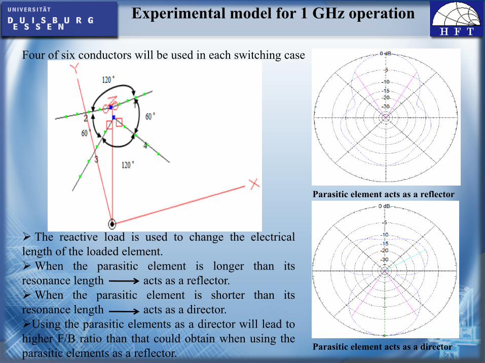
Parasitic element acts as a reflector
Parasitic element acts as a director
Four of six conductors will be used in each switching case
The reactive load is used to change the electricallength of the loaded element.
When the parasitic element is longer than itsresonance length acts as a reflector.
When the parasitic element is shorter than itsresonance length acts as a director.
Using the parasitic elements as a director will lead tohigher F/B ratio than that could obtain when using theparasitic elements as a reflector.

Experimental model for 1 GHz operation
Which reactive load (inductive or capacitive) is better to be connected to the parasiticelements?
When the parasitic element is connected with inductive load.
When the parasitic element is connected with capacitive load.
Both reactive loads could achieve high gain with high F/B ratio by using the suitableconductor's length for each case.
Nevertheless, using a capacitive load is preferred in order to obtain higher return lossvalue.
A further advantage that found from using a capacitive load will be more obviousduring designing a model for 14 MHz operation.

Experimental model for 1 GHz operation
Parameters optimization and simulation results in free space:
In order to achieve the best gain and F/B ratio, conductor’s length and the value ofthe reactive load (capacitive load) should be optimized.
The distance between the driven element (at feed point) and the parasitic element (atreactive load) is required to be small as possible in order to increase the couplingbetween the antenna elements.
Using copper conductors of 0.5mm diameter and a spacing distance of 1cm betweenthe two array elements.
The optimal length of conductors when inserting a capacitive load of 4.7pF at thecenter of parasitic element is 74mm ( ).4λ≈L
RL= -8.4 dB Ω−= 99.4176.51 jZin

Experimental model for 1 GHz operation
Maximum gain (at azimuth plane) = 4.81HPBW = 65.7 degreeF/B pattern ratio = 13.28 dBF/S pattern ratio = 7.32 dB
idB

Experimental model for 1 GHz operation
Realization of 1GHz experimental model (without switch):
The complete structure of antenna installed on the anechoic chamber base.
PCB layout for 1GHz model
cmcm 11 ×

Experimental model for 1 GHz operation
Simulated and measured return loss.
Simulated and measured smith chart graphs
The physical length of antennawires are less than simulated onewith few percents.

Experimental model for 1 GHz operation
Simulated and measured horizontallypolarized radiation pattern.
Simulated and measured verticallypolarized radiation pattern.

Remote Antenna Switch System
Remote switching system allows us to choose from one of several predetermined, fixedbeams, and switch from one beam to another.
It consists basically of two major units, the remote control unit and the remote antennaswitch unit.
RF Generator/Receiver.DC power supply. The rotary switch box Rotary switch
Logic gatesEncoderTransistorsResistors
SPDTRelays
DPDT

Remote Antenna Switch System
The rotary switch box
A rotary switch
1-pole 6-position rotary switch
Logic gatesNOT gate (Inverter)

Remote Antenna Switch System
OR gate
AND gate

Remote Antenna Switch System
Encoder: convert a decimal number to binary number
Active low inputs and outputs
Bipolar Junction Transistors (BJT)

Remote Antenna Switch System
Relay: is an electrical switch, consists basically of two circuits : a control circuit (the coil) and a load circuit (the switch).
Relays with external De-spiking Diodes
Relay De-Energized Relay Energized

Remote Antenna Switch System
SPDT and DPDT relays
SPDT relay DPDT relay
The relays are characterized with low capacitance (ca. 1pf) between contacts.

Remote Antenna Switch System
The switch unit:
RF source
1st wire
2nd wire
3rd wire
4th wire
Reactive load5th wire
6th wire
‐3dB
Routing configuration ofthe switch unit for abeam pointing to 90azimuth
Six overlapping main beamscovering the full 360 degree inazimuth

Remote Antenna Switch System
Designing switch unit PCB
Relays arrangement on PCB
Upper layer Lower layer
The active traces as shown onPCB for 1st case when relaysA, E, F, D, H and G areenergized

Remote Antenna Switch System
Connection patches for RF
cable
Protection diode
Microstrip line
Attachment eye for antenna wire
120 pF capacitor
SPDT relay
Opening for RF cable
DPDT relay
Five wire control cable

Remote Antenna Switch System
How to construct the control unit
The state of relays at each switching case
Representing the state of relays in a binary system

Remote Antenna Switch System
Three-variable Karnaugh maps are extracted from previous table in orderto obtain the logical expressions

Remote Antenna Switch System
Circuit diagram that combines the control circuit and the interfacing circuit
1 21 Control unit2 Interfacing circuit

Remote Antenna Switch System
74LS04 Inverter
Rotary switch (ELMA0116)
74LS147 Encoder
74LS08 2input AND gate
12 Vdc & Gnd
150 Ω power resistor
5kΩ resistor
Five wire control cable
74LS32 2input OR gate
2N2222 Transistor
Remote control unit as appears in reality

Baluns
Baluns are special type of transformers. They are widly used in ham stations.Their primary function is to minimize the interaction of antenna with the
transmission line.
Field between antenna and coaxial cable creates aninduced current on the outside of the shield.
Choke balun is connected at feed point of antenna to decouple the feedline fromthe antenna by inserting high common mode impedance in series with feedline.
High common mode impedance choke off unwanted RF-currents which try toflow on the common mode paths along a feedline.

Baluns
Effect of common mode current in antenna system
The common mode current formed on the outside of theshield would actually cause energy to radiate from thecoax itself, making it appears to be part of the antenna.
The distorted radiation pattern due to the effect of common mode current

Baluns
Constructing Choke balun
With winding number of turns of coax “RG 174” around Ferrite ring “FT240-77”we get a 50Ω, 1:1 choke balun.
The 77 material provides excellent attenuation of RFI caused by amateur radiofrequencies from 2 to 30 MHz.
The attenuation coefficient that achieves for common mode current is -23dB at14MHz.
The common mode impedance that will be inserted is series with feedline is about900 ohm.

A Full function model for short-wave operation (14 MHz)
A full function model for short-wave operation (14 MHz) is simulated and installedabove perfect conductivity ground.
Using insulated copper stranded wireswith cross section of 0.14 .
The optimal length of conductors wheninserting a capacitive load of 120pF atthe center of parasitic element is 5.6m (
).
The geometry of antenna and typicalazimuth pattern for 14 MHz operation.
RL= -25.6 dB Ω−= 087.495.46 jZin
2mm
4λ≈L

A Full function model for short-wave operation (14 MHz)
Simulated horizontally polarized radiation pattern.
Simulated vertically polarizedradiation pattern
The maximum gain of mainbeam is tilted by about 65degree above the groundplane and equal 4.4
The maximum gain of main beam is tilted by about 45 degree above the ground planeand equal 7.44
HPBW = 61.5 degreeF/B pattern ratio = 10 dBF/S pattern ratio = 6 dBDue using copper wires, our model contains losses estimated to be 1.31 dB.0.8 dB losses due coaxial cable
idB
idB

A Full function model for short-wave operation (14 MHz)
A scale drawing of antenna model placed on the platform

A Full function model for short-wave operation (14 MHz)
Our antenna model as seen above the roof platform of BB-building from thesouthwest side. For better visibility, the dipole wires have been colored.

A Full function model for short-wave operation (14 MHz)
Measured and simulated smith chart graphs

A Brief comparison between our switched beam antenna andthe 3-element rotary beam antenna (3-element Yagi)
The 3-element rotary beam antenna represents a high gain antenna rotatedmechanically by using a rotator system
The antenna is set at a 3m height above the roof platform.
A comparative test has been done at14MHz between both antennas andshowed that the received signalstrength by both antennas are almost thesame.
The 3-element rotary beam antenna

Conclusion
A novel switched beam antenna with omni-directional coverage and high gain hasbeen developed.
A special remote antenna switch system has been constructed in order to steer thebeam over a beam scan angle in azimuthal increments.
The six-beams that are obtained from the different antenna arrays are located atwhere the 3 dB-beam widths are about 60 degree.
At 1 GHz the measured radiation pattern in the azimuth plane shows a goodcorrelation with the theoretical prediction.
At 14 MHz the antenna array yields over its entire beam scan range a gain of 7.5dBi, a VSWR of 1.11, beamwidth of 61.5 degree and a front to back ratio of 10 dB.The bandwidth of the array is 1.71 % for a VSWR<2.

Conclusion