Development of a New Steel Moment Connection 116-3 4. Proposed Concept In the proposed gusset plate...
9
Proceedings of the World Congress on Civil, Structural, and Environmental Engineering (CSEE’16) Prague, Czech Republic – March 30 – 31, 2016 Paper No. ICSENM 116 DOI: 10.11159/icsenm16.116 ICSENM 116-1 Development of a New Steel Moment Connection Xin Qian, Abolhassan Astaneh-Asl University of California at Berkeley 781 Davis Hall, Berkeley, CA, 94720-1710, USA [email protected] Abstract - Steel moment frames are widely used in buildings subjected to lateral loads such as wind and earthquakes. This paper summarizes development of a new economical steel moment connection for use in highly seismic areas. The highly ductile new connection is primarily utilizing ductility of the gusset plate to provide necessary rotational capacity while the entire beam and column being connected remain essentially elastic. Due to the desirable performance of the connection and the flat geometry of the gusset plate, the proposed connection is well-suited to be used in steel and composite special ductile moment frames, special steel shear walls and dual systems of moment frames plus special concentrically braced frames, all currently used in seismic lateral force resistance in buildings. The proposed new moment connection can also be used in resisting gravity loads and lateral forces due to wind. In the proposed gusset plate moment connection, the beam is cut short to leave a distance from the column face where yielding and plastic hinge formation are expected to occur primarily due to in-plane yielding of the gusset plate. The gusset plate can either be directly welded to the column or bolted to the column using an end plate. With careful proportioning and proper detailing, the beam is expected to remain essentially elastic during the cyclic loading and no, or minimum continuity plates will be required for the column panel zone. Extensive nonlinear finite element analyses have been conducted. The results indicated that the connection will be very ductile and performs in a very desirable manner when the moment capacity of the gusset plate divided by the moment capacity of the beam ratio is less than 1.0, the thickness of the gusset plate is equal or greater than 1.25 times the beam web thickness and the free gusset plate length is equal to 4 to 6 times the gusset plate thickness. Based on the observation from the studies summarized herein, the use of “Upset bolts” is recommended for the bolted version, where tension bolts connect the gusset plate to the column. Keywords: Structural Engineering, Steel Structures, Moment Connections, Earthquake Engineering, Seismic Design, Bolted Connections, Welded Connections. 1. Introduction Steel moment frames are widely used in buildings subjected to lateral loads like wind and earthquake loads. Many different types and details of moment connections are available in the literature depending on the severity of the imposed loads – in the U.S.; it is categorized into Wind and Low Seismic Applications, where ductility requirements are less stringent, and High-Seismic Applications, where there is a high ductility demand. Design of steel moment connections changed significantly after the 1994 Northridge earthquake, when a number of field-welded steel moment connections were damaged in the form of fracture of the beam-to-column connections welds or areas of the beam and/or column adjacent to the weld. Based on the results of SAC Joint Venture Steel Project and other research effort, a series of recommendations were made to improve the connection design and performance in high seismic applications, the most important one being the higher ductility requirement for the connection as a whole and its elements. The SAC project also resulted in the development of several Prequalified steel moment connections that were validated by analysis and testing to have the necessary strength, stiffness and especially ductility. Fig.1 (a) shows typical Pre-Northridge earthquake connections that experienced damage during the 1994 Northridge earthquake in Los Angeles. Fig. 1(b), (c), and (d) show examples of Pre-qualified connections developed after the Northridge earthquake that are currently used in seismic design for high seismic applications. The innovative ductile Special Gusset Plate Moment (SGPM) connection publicly presented in this paper for the first time, originated from a much larger on-going research projects by the authors to develop new and efficient steel plate shear wall systems. As mentioned earlier, the proposed connection not only can be used very efficiently in Steel Plate Shear Walls, but also in other steel and composite ( steel+ concrete) building structural systems such as the Special Moment Frames and dual system of Special Moment Frame plus Special Concentrically Braced Frames.
Transcript of Development of a New Steel Moment Connection 116-3 4. Proposed Concept In the proposed gusset plate...
Proceedings of the World Congress on Civil, Structural, and Environmental Engineering (CSEE’16)
Prague, Czech Republic – March 30 – 31, 2016
Paper No. ICSENM 116
DOI: 10.11159/icsenm16.116
ICSENM 116-1
Development of a New Steel Moment Connection
Xin Qian, Abolhassan Astaneh-Asl University of California at Berkeley
781 Davis Hall, Berkeley, CA, 94720-1710, USA
Abstract - Steel moment frames are widely used in buildings subjected to lateral loads such as wind and earthquakes. This paper
summarizes development of a new economical steel moment connection for use in highly seismic areas. The highly ductile new
connection is primarily utilizing ductility of the gusset plate to provide necessary rotational capacity while the entire beam and column
being connected remain essentially elastic. Due to the desirable performance of the connection and the flat geometry of the gusset plate,
the proposed connection is well-suited to be used in steel and composite special ductile moment frames, special steel shear walls and
dual systems of moment frames plus special concentrically braced frames, all currently used in seismic lateral force resistance in
buildings. The proposed new moment connection can also be used in resisting gravity loads and lateral forces due to wind. In the proposed
gusset plate moment connection, the beam is cut short to leave a distance from the column face where yielding and plastic hinge formation
are expected to occur primarily due to in-plane yielding of the gusset plate. The gusset plate can either be directly welded to the column
or bolted to the column using an end plate. With careful proportioning and proper detailing, the beam is expected to remain essentially
elastic during the cyclic loading and no, or minimum continuity plates will be required for the column panel zone. Extensive nonlinear
finite element analyses have been conducted. The results indicated that the connection will be very ductile and performs in a very desirable
manner when the moment capacity of the gusset plate divided by the moment capacity of the beam ratio is less than 1.0, the thickness of
the gusset plate is equal or greater than 1.25 times the beam web thickness and the free gusset plate length is equal to 4 to 6 times the
gusset plate thickness. Based on the observation from the studies summarized herein, the use of “Upset bolts” is recommended for the
bolted version, where tension bolts connect the gusset plate to the column.
Keywords: Structural Engineering, Steel Structures, Moment Connections, Earthquake Engineering, Seismic Design, Bolted
Connections, Welded Connections.
1. Introduction Steel moment frames are widely used in buildings subjected to lateral loads like wind and earthquake loads. Many
different types and details of moment connections are available in the literature depending on the severity of the imposed
loads – in the U.S.; it is categorized into Wind and Low Seismic Applications, where ductility requirements are less stringent,
and High-Seismic Applications, where there is a high ductility demand. Design of steel moment connections changed
significantly after the 1994 Northridge earthquake, when a number of field-welded steel moment connections were damaged
in the form of fracture of the beam-to-column connections welds or areas of the beam and/or column adjacent to the weld.
Based on the results of SAC Joint Venture Steel Project and other research effort, a series of recommendations were made
to improve the connection design and performance in high seismic applications, the most important one being the higher
ductility requirement for the connection as a whole and its elements. The SAC project also resulted in the development of
several Prequalified steel moment connections that were validated by analysis and testing to have the necessary strength,
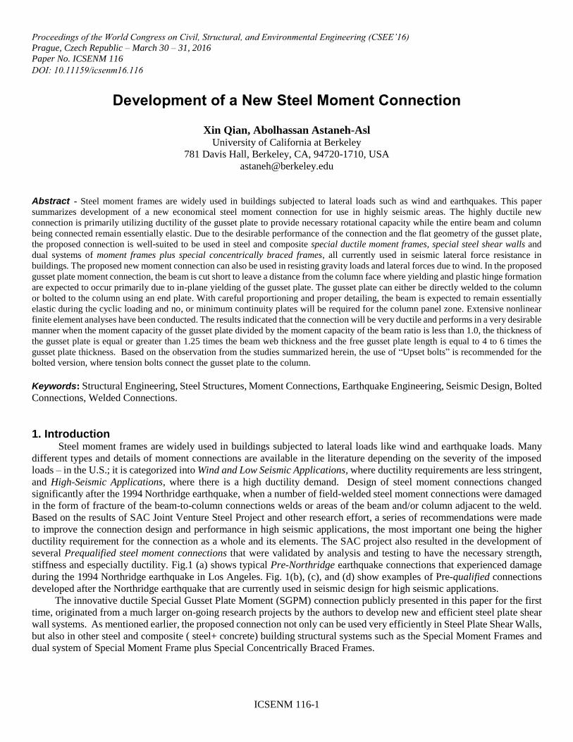
stiffness and especially ductility. Fig.1 (a) shows typical Pre-Northridge earthquake connections that experienced damage
during the 1994 Northridge earthquake in Los Angeles. Fig. 1(b), (c), and (d) show examples of Pre-qualified connections
developed after the Northridge earthquake that are currently used in seismic design for high seismic applications.
The innovative ductile Special Gusset Plate Moment (SGPM) connection publicly presented in this paper for the first
time, originated from a much larger on-going research projects by the authors to develop new and efficient steel plate shear
wall systems. As mentioned earlier, the proposed connection not only can be used very efficiently in Steel Plate Shear Walls,
but also in other steel and composite ( steel+ concrete) building structural systems such as the Special Moment Frames and
dual system of Special Moment Frame plus Special Concentrically Braced Frames.
ICSENM 116-2
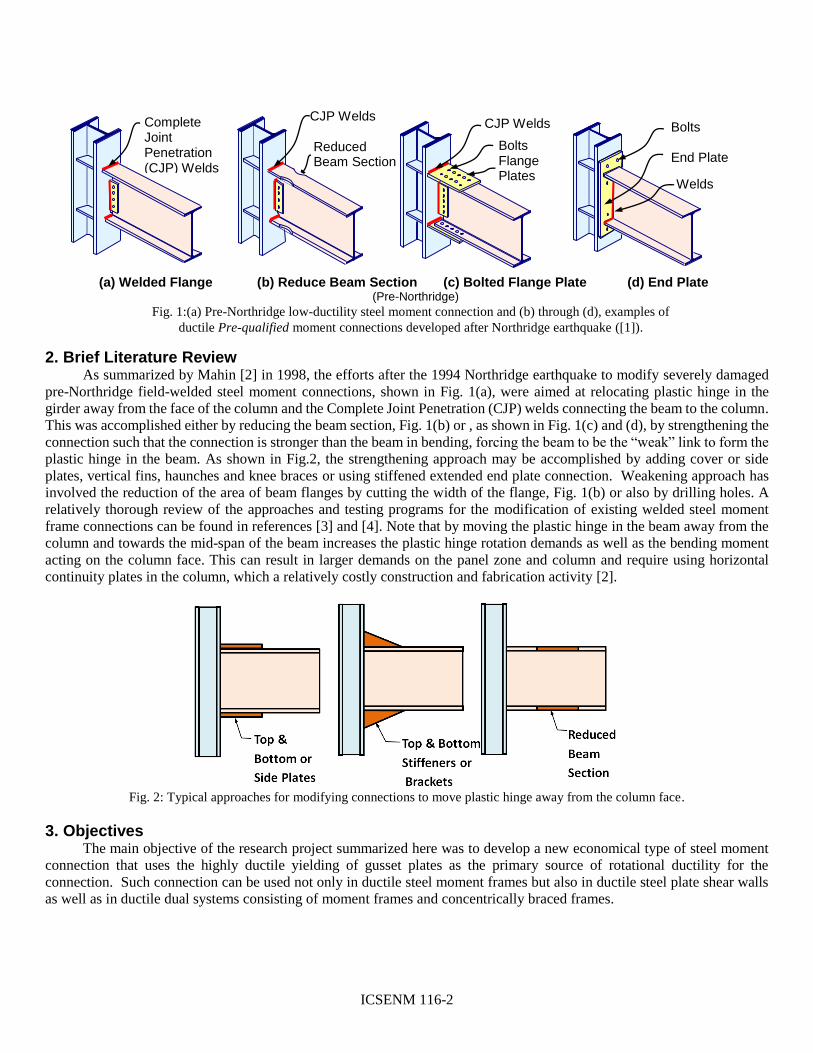
2. Brief Literature Review As summarized by Mahin [2] in 1998, the efforts after the 1994 Northridge earthquake to modify severely damaged
pre-Northridge field-welded steel moment connections, shown in Fig. 1(a), were aimed at relocating plastic hinge in the
girder away from the face of the column and the Complete Joint Penetration (CJP) welds connecting the beam to the column.
This was accomplished either by reducing the beam section, Fig. 1(b) or , as shown in Fig. 1(c) and (d), by strengthening the
connection such that the connection is stronger than the beam in bending, forcing the beam to be the “weak” link to form the plastic hinge in the beam. As shown in Fig.2, the strengthening approach may be accomplished by adding cover or side
plates, vertical fins, haunches and knee braces or using stiffened extended end plate connection. Weakening approach has
involved the reduction of the area of beam flanges by cutting the width of the flange, Fig. 1(b) or also by drilling holes. A
relatively thorough review of the approaches and testing programs for the modification of existing welded steel moment
frame connections can be found in references [3] and [4]. Note that by moving the plastic hinge in the beam away from the
column and towards the mid-span of the beam increases the plastic hinge rotation demands as well as the bending moment
acting on the column face. This can result in larger demands on the panel zone and column and require using horizontal
continuity plates in the column, which a relatively costly construction and fabrication activity [2].
Fig. 2: Typical approaches for modifying connections to move plastic hinge away from the column face.
3. Objectives The main objective of the research project summarized here was to develop a new economical type of steel moment
connection that uses the highly ductile yielding of gusset plates as the primary source of rotational ductility for the
connection. Such connection can be used not only in ductile steel moment frames but also in ductile steel plate shear walls
as well as in ductile dual systems consisting of moment frames and concentrically braced frames.
Fig. 1:(a) Pre-Northridge low-ductility steel moment connection and (b) through (d), examples of
ductile Pre-qualified moment connections developed after Northridge earthquake ([1]).
CJP Welds Reduced Beam Section
(a) Welded Flange (b) Reduce Beam Section (c) Bolted Flange Plate (d) End Plate (Pre-Northridge)
Complete Joint Penetration (CJP) Welds
Welds
Bolts End Plate
Bolts Flange Plates
CJP Welds

ICSENM 116-3
4. Proposed Concept In the proposed gusset plate moment connection, the beam is cut short to leave a distance from the column face.
Yielding and plastic hinge formation is expected to occur primarily due to in-plane yielding of the gusset plate. The gusset
plate can either be connected to the column face by weld or by bolts with end plate as shown in Fig. 3. For the welded option, the gusset plate will be welded to the column face in shop, and the beam to be fit in and welded
to the gusset plate by either fillet weld or partial joint penetration (PJP) weld in field. For relatively thick gusset plate,
complete joint penetration (CJP) weld may be required. For the bolted option, the gusset plate stem will be welded to the
beam in shop with fillet or PJP welds, and bolt holes drilled in the gusset flange. Corresponding bolt holes in the column
flange will also be prepared before transporting to the field. Then the pre-fabricated gusset plus beam module can be bolt
connected to the column in field. The proposed connection design can avoid the use of complete joint penetration (CJP)
welds and corresponding required inspection with ultra-sonic sound testing for gusset plate with thin or common thickness.
After discussion with steel manufacturers, other methods are also possible to connect the beam to the gusset plate, for
example, by using welded or bolted slotted connection plates. Fig. 4 shows examples of other possible details for the
proposed gusset plate moment connection.
Fig. 3: Illustration of the proposed gusset plate moment connection.
Fig. 4: Other feasible details for the proposed gusset plate moment connection currently under development by authors.
The proposed configuration, by appearance, is analogous to the stiffened extended end-plate moment connection,
except a gap is designed between the end of the beam and the column face, which brings in additional ductility and energy
dissipation capability to the system. More importantly, unlike the stiffened end plate connection and all current prequalified
connections, which have plastic hinge forming in the beam, in the proposed new Special Gusset Plate Moment Connection
Beam Flanges Slotted Here
Top and Bottom Plates Slotted Here
Top and Bottom Plates Slotted Here
(a) Welded Slotted Beam (b) Bolted Slotted Top-and- (c) Welded Slotted Top-and- Bottom Plates Bottom Plates

ICSENM 116-4
(SGPMC), the plastic hinge forms in the gusset plate and not in the beam. This results in the beam not being the inelastic
element of the seismic force resisting system, thus, not requiring the very stringent limitations on the slenderness of its web
and flanges to prevent local buckling. In essence, the design philosophy of the proposed new gusset plate moment connection
can be looked at as being similar to the design philosophy of the reduced beam section (RBS) moment connection shown in
Fig. 1(b) earlier. In both cases, instead of designing the connection to be stronger than the member, as is the case for
connections in Fig. 1(c) and (d), the beam is designed to satisfy the gravity load strength demand and lateral load stiffness
demand and the gusset plate connection is designed to satisfy seismic strength and ductility demand, and acts as a fuse.
The major difference between the proposed moment connection and the reduced beam moment connection or other
Pre-qualified moment connections currently in use is that, instead of moving the plastic hinge away from the column and
into the beam, in the proposed new gusset plate moment connection, the plastic hinge location is moved closer to the face of
the column and forms inside the ductile element of connection, which is the gusset plate. As a result, the beam can be
designed to remain elastic during the cyclic loading and the column web will not experience very high stresses in the panel
zone area since yielding of the beam and the column is prevented by the yield capacity of the gusset plate which acts as an
inelastic fuse. Another advantage of the proposed gusset plate moment connection is that the gusset plate transfers the
bending moment at the end of the beam directly to the column web, instead of column flanges as is the case for other currently
available moment connections. This is due to the fact that both gusset plate and column web are in the same vertical plane.
This allows no, or minimum continuity plates to be needed for the column to protect the column flanges from distortion as
is the case for other moment connections.
5. Nonlinear Finite Element Analyses 5.1. Modelling Material and Geometry
Four-node SHELL181 element from the ANSYS Shell element library were used to model all components in the
beam-to-column connection subassemblies. Since the development of the proposed gusset moment connection was originally
inspired by the ongoing study of the steel plate shear wall system by the authors, the mesh refinement study and material
properties are based on information in reference [5]. Plasticity with multi-linear kinematic hardening material model was
used to better capture the Bauchinger effect. Ramberg-Osgood material model was applied to define the entire stress-strain
relationship, which was found to be able to better represent the strain hardening behavior observed in the test in reference
[5]. For the bolted gusset plate moment connection option shown in Fig. 3(b) earlier, the bolts were modeled with beam
element BEAM188 of ANSYS, with bilinear kinematic hardening material model and frictional contact element with
coefficient of friction of 0.20 between the gusset plate assembly and the column flange surfaces. Residual stress and initial
imperfection were not included in the model during the development of the proposed connection presented in this paper. It
is believed that such minor imperfections do not have noticeable effect on inelastic behavior of connections.
5.2. Simulation Set-up A typical beam-to-column sub-assembly was developed using the SC4T specimen dimensions in ref [5] as shown in
Fig.5. The loading history is created based on the ATC-24 loading protocol for stepwise increasing cyclic tests.
Fig. 5: Details of test set-up showing the boundary condition for the connection subassembly and the loading history.
0 5 10 15 20 25 30 35 40 45-0.04
-0.03
-0.02
-0.01
0
0.01
0.02
0.03
0.04
Time Step
Inte
rsto
ry D
rift A
ng
le
Lfg Cyclic
Push-Pull Force
Inter-story Drift Angle
(Free Length of Gusset Plate)

ICSENM 116-5
6. Results 6.1. Behaviour of Gusset Plate Moment Connection
a. Comparison of proposed welded and bolted connections
First we simulated four different configurations of our proposed gusset plate connections which included (a) welded
option with 1.0tbw gusset plate thickness (b) welded option with 1.5tbw gusset plate thickness (c) bolted option with 1.0tbw
gusset plate stem thickness (with bilinear bolt model) (d) bolted option with 1.0tbw gusset plate stem thickness (bilinear bolt
model + 70% pretension).
The hysteretic loops for four connections are plotted in Fig. 6. For welded connections ( top row in Fig. 6), it can be
seen that assuming the welds are strong and ductile enough, the welded option showed stable and stocky hysteresis loops
with relatively large energy dissipation for both cases of gusset plate thickness. With larger gusset thickness (i.e. tg=1.5 tbw),
the maximum peak value of the reaction force increased by about 38% compared to the case, when the thickness of the gusset
was equal to the thickness of the beam web (i.e. tg=1.0 tbw). The increase in the capacity is slightly less than the percentage
of increase in the thickness, which was 50%.
For bolted connections, as shown in the bottom row of Fig. 6, hysteresis loops were pinched and have lower energy
dissipation capacity, which is to great extent because of insufficient number of bolts used in the models. This problem could
possibly be resolved by redesigning the bolts such that they remain elastic throughout the cyclic loading. The pinching of
hysteresis loops can also be reduced by making the flange of the gusset plate thicker. It should be noted that even though
less energy can be dissipated due to pinched hysteresis loops, at the same force level, the bolted option could provide larger
deformation, making the connection more ductile. Also, parameters not included in the modelling, such as the bolt slippage
can result in increased ductility of the connection. Finally, with bolt pre-tension, the unloading branch becomes less smooth
and less curved. The reason could be the additional linearity of bolt pretension brought into the connection. Since bolts
connecting the gusset to the column are under combined tension and shear forces, the use of “Upset bolts” is recommended. In Upset bolts, the diameter of shank is less than the diameter of the threaded part to force yielding of unthreaded part of the
bolt to occur prior to fracture of the threaded parts to ensure ductility and avoid fracture of the bolt.
Fig. 6: Hysteresis loops of gusset beam-to-column connection sub-assembly.
-0.05 0 0.05
-400
-200
0
200
400
Drift Ratio
Late
ral F
orc
e R
eactio
n(k
N)
(b) Welded Option, tg= 1.5 t
bw
-0.05 0 0.05
-400
-200
0
200
400
Drift Ratio
Late
ral F
orc
e R
eactio
n(k
N)
(a) Welded Option, tg=
-0.05 0 0.05
-400
-200
0
200
400
Drift Ratio
Late
ral F
orc
e R
eactio
n(k
N)
(c)Bolted Option, tg= t
bw
(bolts not pre-tensioned)
-0.05 0 0.05
-400
-200
0
200
400
Drift Ratio
Late
ral F
orc
e R
eactio
n(k
N)
(d) Bolted Option, tg= t
bw
(bolts pre-tensioned)
ICSENM 116-6
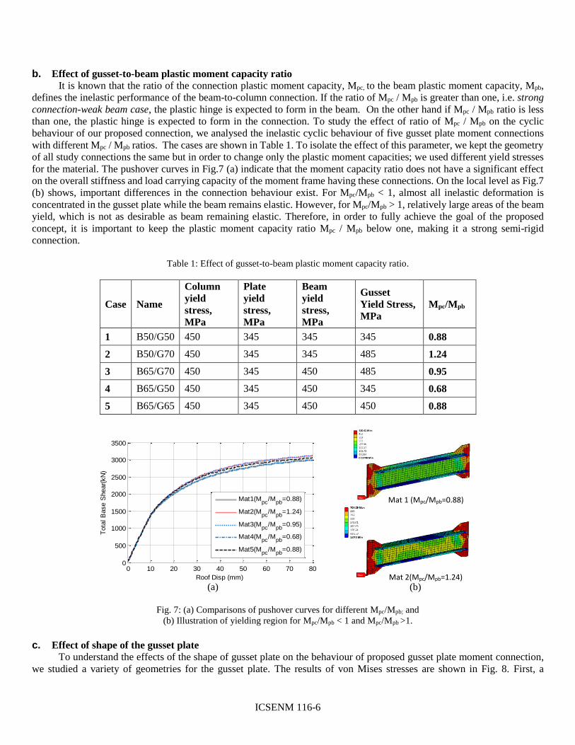
b. Effect of gusset-to-beam plastic moment capacity ratio
It is known that the ratio of the connection plastic moment capacity, Mpc, to the beam plastic moment capacity, Mpb,
defines the inelastic performance of the beam-to-column connection. If the ratio of Mpc / Mpb is greater than one, i.e. strong
connection-weak beam case, the plastic hinge is expected to form in the beam. On the other hand if Mpc / Mpb ratio is less
than one, the plastic hinge is expected to form in the connection. To study the effect of ratio of Mpc / Mpb on the cyclic
behaviour of our proposed connection, we analysed the inelastic cyclic behaviour of five gusset plate moment connections
with different Mpc / Mpb ratios. The cases are shown in Table 1. To isolate the effect of this parameter, we kept the geometry
of all study connections the same but in order to change only the plastic moment capacities; we used different yield stresses
for the material. The pushover curves in Fig.7 (a) indicate that the moment capacity ratio does not have a significant effect
on the overall stiffness and load carrying capacity of the moment frame having these connections. On the local level as Fig.7
(b) shows, important differences in the connection behaviour exist. For Mpc/Mpb < 1, almost all inelastic deformation is
concentrated in the gusset plate while the beam remains elastic. However, for Mpc/Mpb > 1, relatively large areas of the beam
yield, which is not as desirable as beam remaining elastic. Therefore, in order to fully achieve the goal of the proposed
concept, it is important to keep the plastic moment capacity ratio Mpc / Mpb below one, making it a strong semi-rigid
connection.
Table 1: Effect of gusset-to-beam plastic moment capacity ratio.
Case Name
Column
yield
stress,
MPa
Plate
yield
stress,
MPa
Beam
yield
stress,
MPa
Gusset
Yield Stress,
MPa
Mpc/Mpb
1 B50/G50 450 345 345 345 0.88
2 B50/G70 450 345 345 485 1.24
3 B65/G70 450 345 450 485 0.95
4 B65/G50 450 345 450 345 0.68
5 B65/G65 450 345 450 450 0.88
Fig. 7: (a) Comparisons of pushover curves for different Mpc/Mpb; and
(b) Illustration of yielding region for Mpc/Mpb < 1 and Mpc/Mpb >1.
c. Effect of shape of the gusset plate
To understand the effects of the shape of gusset plate on the behaviour of proposed gusset plate moment connection,
we studied a variety of geometries for the gusset plate. The results of von Mises stresses are shown in Fig. 8. First, a
Mat 2(Mpc/Mpb=1.24)
Mat 1 (Mpc/Mpb=0.88)
0 10 20 30 40 50 60 70 800
500
1000
1500
2000
2500
3000
3500
Roof Disp (mm)
Tota
l B
ase S
hear(
kN
)
Mat1(Mpc
/Mpb
=0.88)
Mat2(Mpc
/Mpb
=1.24)
Mat3(Mpc
/Mpb
=0.95)
Mat4(Mpc
/Mpb
=0.68)
Mat5(Mpc
/Mpb
=0.88)
(a) (b)

ICSENM 116-7
rectangular gusset plate of dimension 394mm by 210mm was analysed. The plot of von Mises stresses showed that the
yielded region is roughly in the form of two intersected “bell” shapes, similar to Whitmore’s areas [6], around the roots of
the gusset-to-beam flange connection, while the areas of the gusset plate outside this highly stressed areas show not much of
stress. For this rectangular gusset plate, the maximum plastic strain occurred at the intersection of the vertical side to the
beam flange (Fig.8 Case Rect 1 on top-left). Based on such observations, five other slightly modified gusset plate shapes
were developed, mainly aiming to make more efficient use of the section following the stress distribution and reduce the
strain concentrations. Case Rect 2 (top-right corner of Fig 8) was selected to study the size effect.
It was observed that peak stress/strain often occurs at three critical locations – root of the gusset horizontal side-to-
column weld, root of gusset vertical side-to-beam flange weld, and root of mid gusset-to-beam flange edge (denoted as
yellow dots in Fig.8). Larger gusset plates were found to provide more capacity but caused greater yielding in the columns
and beams, which is undesirable. Gusset plate geometry Trap 2 was considered most efficient and desirable among the
analysed geometries since the yielded point with maximum equivalent plastic strain for this case was located within the
gusset plate surrounded by essentially elastic elements instead of yielded zone being at the free edge of the gusset plate. In
a plate, whenever yielded elements are relatively small and are surrounded entirely by elastic elements, such yielding will
remain confined and can be ignored. In addition, with the well-established Whitmore section for gusset plate design in
braced frames [6] and [7], a value of 20 to 30 degrees for the angle of slope of gusset plate edge, , is found to be appropriate
for the proposed gusset plate beam-to-column moment.
Fig. 8: Comparison of dimensions and of maximum equivalent plastic strain regions for different gusset plate shapes.
d. Effect of thickness of the gusset plate Cases with gusset plate thickness being 1.0, 1.25 and 1.5 times the beam web thickness were analysed. Based on the cases
analysed and to avoid large yielding in beam and column and gusset plate buckling, a gusset plate thickness of 1.25 times
the beam web is recommended to be used if the yield stresses of the gusset and beam material are the same.
e. Effect of free gusset length
The free gusset length of the gusset plate, Lfg, is defined as the distance between the end of the beam to the face of the column
as was shown in Fig.3 earlier. For the models simulated, Lfg was varied as percentage of the beam depth db (30%, 40%,
47.5%, 60% and 75%), which can also be expressed as multiples of gusset plate thickness tg. For example, for tg equal to tbw,
the ratio Lfg /tg correspond to 4, 5, 6, 7.5 and 9.
Fig. 9 shows that as the free gusset length decreases, regardless of the thickness of the gusset plate, the overall shear capacity
of the beam-to-column connection increases and less out-of-plane deformation of the gusset plate was observed. By using a
small Lfg, which is similar to the directly welded beam-to-column connection with triangular stiffening plates, the column

ICSENM 116-8
web will be subjected to larger force due to gusset plate yielding. From the parametric study, the preferred value for free
length, Lfg, for the gusset plate is 4 to 6 times the thickness of the gusset plate. In addition to controlling the Lfg and tg value
to prevent the degradation of behaviour due to out-of-plane deformation of gusset plate, one may also consider to provide
lateral support to the beam lower flange if possible.
Fig. 9: Comparison of cyclic hysteresis loops and gusset plate out-of-plane deformation.
7. Conclusion In conclusion, a new economical steel moment connection that mainly makes use of the ductility of the gusset plate is
proposed in this paper. The use of gusset plate and the proposed configuration allows the beam to remain elastic during the
cyclic loading while almost all of the inelastic deformation and energy dissipation is in the gusset plate. No, or minimum
continuity plates will be required for the column panel zone due to formation of plastic hinge in the gusset plate close to the
column face. With the flat gusset plate, the proposed connection can also be easily integrated into steel plate shear wall lateral
force resisting system. The proposed gusset plate innovative moment connection can also be efficiently used in a dual system
of special concentrically braced frames combined with moment frames.
Based on nonlinear finite element analyses, key observations and recommendations are: 1) the gusset-to-beam moment
capacity ratio should be kept smaller than one, 2) a gusset thickness of 1.25 times the beam web thickness and a free gusset
length of 4 to 6 times the gusset thickness are recommended, and 3) use of upset bolts is suggested for the bolted option to
increase ductility of bolts that are in tension.
Acknowledgements This study was part of a larger project on “Investigation of Seismic Performance of Moment Frames and Steel Shear Walls” at the University of California Berkeley, USA, with Prof. Abolhassan Astaneh-Asl as the Principal Investigator. The
authors would like to express their sincere appreciation for the tremendous technical support provided by Dr. Metin Ozen,
President as well as Casey Heydari, and the analysts at Ozen Engineering Inc. (https://www.ozeninc.com/) on the use of the
powerful ANSYS nonlinear structural analysis software featured in this project. The authors also wish to thank Mr. Brett
Manning, Vice President Northwest Sales / Engineering, Schuff Steel for his valuable technical advice in developing the
new innovative steel moment connection.
References [1] A. Astaneh-Asl, “Behavior and Design of Steel Structures,” Fall 2015 Ed., 2015.
[2] S. A. Mahin, “Lessons from Damage to Steel Buildings during the Northridge Earthquake,” Engineering Structures,
vol. 20, no. 4-6, pp. 261-70, 1998.
[3] SAC Joint Venture, “Interim guidelines: evaluation, repair, modification and design of welded steel moment frame
structures,” Report FEMA 267/SAC Report 95-02, Federal Emergency Management Agency: Washington DC, 1995.
[4] SAC Joint Venture, “Connection Test Summaries,” Report FEMA 289/SAC Report 96-02, Federal Emergency
Management Agency: Washington DC, 1997
[5] H. G. Park., et al., “Framed steel plate wall behaviour under cyclic lateral loading,” Journal of structural engineering,
vol. 133, no. 3, pp. 378-388, 2007.
[6] A. Astaneh-Asl, Seismic Behavior and Design of Gusset Plates. CA: Structural Steel Educational Council, 1998.
-0.05 0 0.05-400
-200
0
200
400
Trap 2, tw
=1.0tbw
Drift Ratio
Bas
e S
hear
(kN
)
-0.05 0 0.050
10
20
30
40
50
Drift Ratio
Out
-of-
plan
e de
form
atio
n(m
m)
H2=30%d
b
H2=47.5%d
b
H2=75%d
b
-0.05 0 0.05-400
-200
0
200
400
Trap 2, tw
=1.25tbw
Drift Ratio
Bas
e S
hear
(kN
)
-0.05 0 0.050
2
4
6
8
10
Drift Ratio
Out
-of-
plan
e de
form
atio
n(m
m)
H2=30%d
b
H2=47.5%d
b
H2=75%d
b
Bas
e Sh
ear
(kN
)
Drift Ratio Drift Ratio
tg=1.0tbw tg=1.25tbw
Bas
e Sh
ear
(kN
)

ICSENM 116-9
[7] A. Astaneh-Asl, M. L. Cochran, and R. Sabelli, Seismic Detailing of Gusset Plates for Special Concentrically Braced
Frames. CA: Structural Steel Educational Council, 2006.