Development of a New High-Performance Overhead · PDF fileDevelopment of a New...
9
Development of a New High-Performance Overhead Conductor Rail Using Simulation Models, and their Validation through Field Testing J. Paulin 1 , J.D. Sanz 1 , A. García 1 , C. Vera 2 1 Railway Technology Research Centre, Madrid, Spain; 2 Polytechnic University of Madrid, Madrid, Spain Abstract Overhead rail current collector systems for railway traction are primarily used in underground networks and other railway installations where tunnels are present due to their advantages, such as low installation heights and reduced maintenance. A new design for an improved overhead conductor rail has been developed in cooperation with Metro de Madrid and has been presented in [6]. Modern simulation and modelling techniques were used in the design process that was based on the results obtained in a sensitivity study realized with combined pantograph – conductor rail simulation models. Highly detailed, three-dimensional finite-element and multi-body-system models were used in simulation and reflected well the real system. The newly developed overhead conductor rail allows higher running speeds for new vehicles or an increase in support spacing reducing installation costs. Due to the excellent results that the new overhead conductor rail has given in simulation and prototype testing on real lines, its design has been patented (European patent nº EP 1484214) [10]. In order to validate the simulation models, measuring techniques have been applied to both a pantograph and a section of the new conductor rail. The measuring pantograph assesses the contact force that appears between pantograph and catenary, quantifies other important information, such as the vertical and lateral position of the conductor rail’s contact wire, and records electric arcing. The experimental data obtained in field testing has been compared to the corresponding results given in simulation, and the model has been validated properly. The measurement results have also confirmed the superior dynamic behaviour of the new overhead conductor rail as was predicted by simulation. Introduction In recent years the demand of new railway installations in cities all over the world has increased significantly. High running speeds are needed in order to deal with the growing number of passengers to be transported. Detailed studies of the pantograph-catenary interaction are required so that both a proper catenary system and an appropriate pantograph can be chosen. In this sense, modelling and simulating tools can be of great use when analysing already existing systems or when developing new designs. By means of these techniques it is possible to perform sensitivity studies, which facilitate the optimisation of new systems as well as the improvement of existing ones. The present paper shows the work undertaken by the Railway Technology Research Centre (CITEF) of the Polytechnic University of Madrid (UPM) in collaboration with Madrid Underground’s Engineering Department (Metro de Madrid). The aim of this project was the development of a new overhead conductor rail that had a dynamic behaviour superior to that of the classic conductor rail primarily installed in Madrid’s underground lines. The new design allows either an increase in the distance between catenary supports, currently separated by 10 m, or an increase in running speed, which at present does not exceed 110 km/h. Both options lead to saving in overall costs: reduction of installation costs in the first case and reduction of exploitation costs in the second. As mentioned before, this work has been realized by means of advanced simulation techniques. Particularly, the ANSYS program was used for finite element modelling, and the SIMPACK program for multibody systems analysis. Overhead conductor rail current collection for railway traction The classic overhead conductor rail [1-4] consists of two solidly joined conductor elements: an aluminium conductor rail and a copper contact wire. The catenary cross section (Figure 1) remains unchanged along all of its length. The aluminium conductor rail has a hollow pentagonal shape that presents an opening in the lower end consisting of two clamping arms or flanges, which hold the contact wire. Both flanges
-
Upload
nguyenkhanh -
Category
Documents
-
view
217 -
download
0
Transcript of Development of a New High-Performance Overhead · PDF fileDevelopment of a New...

Development of a New High-Performance Overhead Conductor Rail Using Simulation Models, and their Validation through Field Testing
J. Paulin1, J.D. Sanz1, A. García1, C. Vera2
1Railway Technology Research Centre, Madrid, Spain; 2Polytechnic University of Madrid, Madrid, Spain
Abstract
Overhead rail current collector systems for railway traction are primarily used in underground networks and other railway installations where tunnels are present due to their advantages, such as low installation heights and reduced maintenance. A new design for an improved overhead conductor rail has been developed in cooperation with Metro de Madrid and has been presented in [6]. Modern simulation and modelling techniques were used in the design process that was based on the results obtained in a sensitivity study realized with combined pantograph – conductor rail simulation models. Highly detailed, three-dimensional finite-element and multi-body-system models were used in simulation and reflected well the real system. The newly developed overhead conductor rail allows higher running speeds for new vehicles or an increase in support spacing reducing installation costs. Due to the excellent results that the new overhead conductor rail has given in simulation and prototype testing on real lines, its design has been patented (European patent nº EP 1484214) [10]. In order to validate the simulation models, measuring techniques have been applied to both a pantograph and a section of the new conductor rail. The measuring pantograph assesses the contact force that appears between pantograph and catenary, quantifies other important information, such as the vertical and lateral position of the conductor rail’s contact wire, and records electric arcing. The experimental data obtained in field testing has been compared to the corresponding results given in simulation, and the model has been validated properly. The measurement results have also confirmed the superior dynamic behaviour of the new overhead conductor rail as was predicted by simulation.
Introduction
In recent years the demand of new railway installations in cities all over the world has increased significantly. High running speeds are needed in order to deal with the growing number of passengers to be transported. Detailed studies of the pantograph-catenary interaction are required so that both a proper catenary system and an appropriate pantograph can be chosen. In this sense, modelling and simulating tools can be of great use when analysing already existing systems or when developing new designs. By means of these techniques it is possible to perform sensitivity studies, which facilitate the optimisation of new systems as well as the improvement of existing ones. The present paper shows the work undertaken by the Railway Technology Research Centre (CITEF) of the Polytechnic University of Madrid (UPM) in collaboration with Madrid Underground’s Engineering Department (Metro de Madrid). The aim of this project was the development of a new overhead conductor rail that had a dynamic behaviour superior to that of the classic conductor rail primarily installed in Madrid’s underground lines. The new design allows either an increase in the distance between catenary supports, currently separated by 10 m, or an increase in running speed, which at present does not exceed 110 km/h. Both options lead to saving in overall costs: reduction of installation costs in the first case and reduction of exploitation costs in the second. As mentioned before, this work has been realized by means of advanced simulation techniques. Particularly, the ANSYS program was used for finite element modelling, and the SIMPACK program for multibody systems analysis.
Overhead conductor rail current collection for railway traction
The classic overhead conductor rail [1-4] consists of two solidly joined conductor elements: an aluminium conductor rail and a copper contact wire. The catenary cross section (Figure 1) remains unchanged along all of its length. The aluminium conductor rail has a hollow pentagonal shape that presents an opening in the lower end consisting of two clamping arms or flanges, which hold the contact wire. Both flanges

support the contact wire firmly along its grooves, retaining it through elastic deflection pre-stressing. This way, a correct fastening between both elements is ensured.
Figure 1: Classic overhead conductor rail (cross section and view with support installation).
Pieces of the conductor rail with a nominal length of, e.g. 10 m, are manufactured by aluminium extrusion. These pieces are connected to each other by means of joint elements, called bridles, thus forming longer spans up to 500 m, called overlap sections. Between two adjoining overlap sections a mechanical discontinuity is introduced, which allows for the free thermal expansion of both ends. If electrical continuity is required, the two overlap sections can be shortcut. In order to guaranty continuity throughout the passing of the pantograph, the ends of both sections overlap longitudinally. The ends of each section are curved upwards so that a smooth passing of the pantograph is guaranteed. The overhead conductor rail is suspended from the tunnel roof by means of supports. The distance between these catenary supports is equal to the length of the aluminium pieces. During the installation process, the supports are placed to either side of the centre of the track, giving the conductor rail a sinusoidal shape in the horizontal plane. This configuration, known as ‘stagger’, spreads the wear uniformly across the width of the pantograph’s contact strips.
Advantages and disadvantages
The overhead conductor rail system disposes of a set of advantages in comparison to other electrification systems. The main advantages offered by this system are: • The simplicity and robustness of its components, simplifying installation and maintenance. • The considerable height above the track, reducing the risk of accidental contact. • The reduced installation height required (due to the absence of the conventional catenary wire as well
as to the simplicity of its supports). • The absence of tensile forces in the contact wire, reducing the critical section for worn contact wires
and increasing the mean time interval between wire replacements (in case of overhead conductor rail installations, the contact wire is usually not replaced until its section is so small that the pantograph’s collector strips touch the aluminium profile).
• The great surface area, improving the system’s own refrigeration and lowering the risk of melting by overheating.
• The great conductor section, allowing high current intensities and eliminating the necessity of feeders (therefore, overhead conductor rail systems are suitable for low electric voltages).
Maybe the best known advantage is the one of the reduced installation height required. This advantage makes overhead conductor rail systems so interesting for their application in tunnels, and these systems are increasingly being chosen for city underground systems as well as for main line tunnels. Despite of all the advantageous properties, overhead conductor rail systems have some significant disadvantages:
• The absence of tensile forces in the contact wire, in combination with the high linear weight of the conductor rail, causing great static deflections of the catenary. These deflections are harmful to the system’s dynamics, and are usually limited by reducing the distance between supports.
• This same phenomenon prevents high running speeds from being reached.
Development of catenary and pantograph models
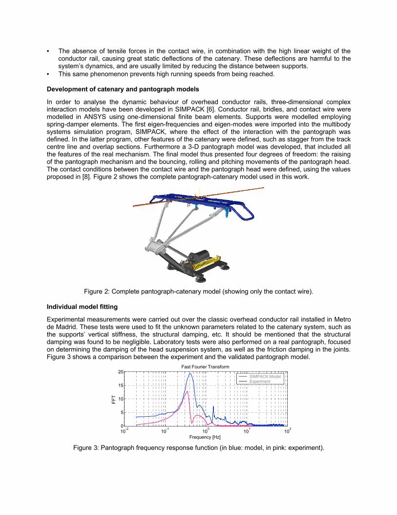
In order to analyse the dynamic behaviour of overhead conductor rails, three-dimensional complex interaction models have been developed in SIMPACK [6]. Conductor rail, bridles, and contact wire were modelled in ANSYS using one-dimensional finite beam elements. Supports were modelled employing spring-damper elements. The first eigen-frequencies and eigen-modes were imported into the multibody systems simulation program, SIMPACK, where the effect of the interaction with the pantograph was defined. In the latter program, other features of the catenary were defined, such as stagger from the track centre line and overlap sections. Furthermore a 3-D pantograph model was developed, that included all the features of the real mechanism. The final model thus presented four degrees of freedom: the raising of the pantograph mechanism and the bouncing, rolling and pitching movements of the pantograph head. The contact conditions between the contact wire and the pantograph head were defined, using the values proposed in [8]. Figure 2 shows the complete pantograph-catenary model used in this work.
Figure 2: Complete pantograph-catenary model (showing only the contact wire).
Individual model fitting
Experimental measurements were carried out over the classic overhead conductor rail installed in Metro de Madrid. These tests were used to fit the unknown parameters related to the catenary system, such as the supports’ vertical stiffness, the structural damping, etc. It should be mentioned that the structural damping was found to be negligible. Laboratory tests were also performed on a real pantograph, focused on determining the damping of the head suspension system, as well as the friction damping in the joints. Figure 3 shows a comparison between the experiment and the validated pantograph model.
10-2
10-1
100
101
102
0
5
10
15
20
Frequency [Hz]
FFT
Fast Fourier Transform
SIMPACK ModelExperiment
Figure 3: Pantograph frequency response function (in blue: model, in pink: experiment).
Sensitivity study of the different design parameters
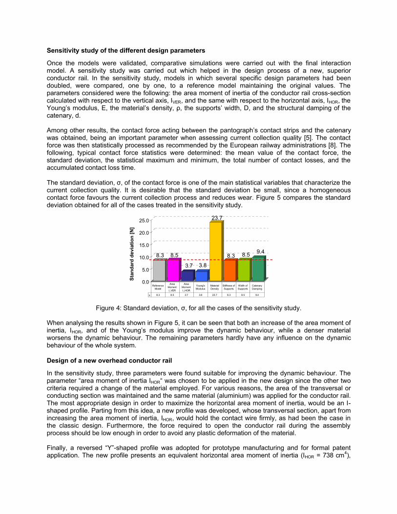
Once the models were validated, comparative simulations were carried out with the final interaction model. A sensitivity study was carried out which helped in the design process of a new, superior conductor rail. In the sensitivity study, models in which several specific design parameters had been doubled, were compared, one by one, to a reference model maintaining the original values. The parameters considered were the following: the area moment of inertia of the conductor rail cross-section calculated with respect to the vertical axis, IVER, and the same with respect to the horizontal axis, IHOR, the Young’s modulus, E, the material’s density, 㰐, the supports’ width, D, and the structural damping of the catenary, d. Among other results, the contact force acting between the pantograph’s contact strips and the catenary was obtained, being an important parameter when assessing current collection quality [5]. The contact force was then statistically processed as recommended by the European railway administrations [8]. The following, typical contact force statistics were determined: the mean value of the contact force, the standard deviation, the statistical maximum and minimum, the total number of contact losses, and the accumulated contact loss time. The standard deviation, 㰰, of the contact force is one of the main statistical variables that characterize the current collection quality. It is desirable that the standard deviation be small, since a homogeneous contact force favours the current collection process and reduces wear. Figure 5 compares the standard deviation obtained for all of the cases treated in the sensitivity study.
8.3 8.5
3.7 3.8
23.7
8.3 8.5 9.4
0.0
5.0
10.0
15.0
20.0
25.0
Stan
dard
dev
iatio
n [N
]
s 8.3 8.5 3.7 3.8 23.7 8.3 8.5 9.4
Reference Model
Area Moment I_VER
Area Moment I_HOR
Young's Modulus
Material Density
Stiffness of Supports
Width of Supports
Catenary Damping
Figure 4: Standard deviation, 㰰, for all the cases of the sensitivity study.
When analysing the results shown in Figure 5, it can be seen that both an increase of the area moment of inertia, IHOR, and of the Young’s modulus improve the dynamic behaviour, while a denser material worsens the dynamic behaviour. The remaining parameters hardly have any influence on the dynamic behaviour of the whole system.
Design of a new overhead conductor rail
In the sensitivity study, three parameters were found suitable for improving the dynamic behaviour. The parameter “area moment of inertia IHOR“ was chosen to be applied in the new design since the other two criteria required a change of the material employed. For various reasons, the area of the transversal or conducting section was maintained and the same material (aluminium) was applied for the conductor rail. The most appropriate design in order to maximize the horizontal area moment of inertia, would be an I-shaped profile. Parting from this idea, a new profile was developed, whose transversal section, apart from increasing the area moment of inertia, IHOR, would hold the contact wire firmly, as had been the case in the classic design. Furthermore, the force required to open the conductor rail during the assembly process should be low enough in order to avoid any plastic deformation of the material. Finally, a reversed “Y”-shaped profile was adopted for prototype manufacturing and for formal patent application. The new profile presents an equivalent horizontal area moment of inertia (IHOR = 738 cm4),

which is a 74 % higher than that of the classic profile. However, the transversal area remains the same (A ≈ 2118 mm2).The final profile, called “METRO_730”, is shown in Figure 6.
Figure 5: New design: “METRO_730” (cross section, prototype, cross section with bridles).
Comparison of the dynamic behaviour of both profiles in simulation
In order to compare the dynamic behaviour of the new profile to the classic one, various simulations were realized in SIMPACK. A direct comparison between both profiles will be presented. The dynamic behaviour of both models was simulated for a 98-m-long straight overlap section with a nominal distance of 10 m between supports and a constant running velocity of 110 km/h. A statistical analysis showed that the standard deviation of the contact force was reduced to almost half the original value, being the corresponding values for the classic and the new profiles:
㰰classic = 8.3 N 㰰 new = 4.5 N Low values for the standard deviation indicate a good dynamic behaviour of the interaction between pantograph and conductor rail. Since the new design had a better dynamic behaviour than the classic one, it was wondered to what degree the distance between supports could be increased for the new conductor rail without obtaining worse results in the dynamic behaviour than the classic profile. Distances of 10, 12 and 14 m were simulated with the pantograph passing at a constant speed of 110 km/h. The statistical results for both profiles are presented together, for distances between supports of 10, 12 and 14 m and a constant velocity of 110 km/h. As can be seen in Figure 6, the new profile at 12 m has a very similar response to the classic profile at 10 m. A slightly worse behaviour is obtained when increasing the separation between supports to 14 m.
8.3
4.5
13.5
7.4
17.9
10.6
0.0
5.0
10.0
15.0
20.0
Sta
nd
ard
devia
tio
n [
N]
[10 m] [12 m] [14 m]
CLASSICNEW
Figure 6: Standard deviation of the contact force, for 110 km/h.
Another possibility in order to obtain the same dynamic behaviour for both profiles, was to increase the pantograph’s running velocity. Running speeds of 110, 140, and 150 km/h were simulated for a constant support spacing of 10 m. Figure 7 shows the statistical results for the contact forces. As before, the

standard deviations of both profiles are represented in the same graph. As can be seen, the standard deviation for the current profile at 110 km/h falls between the ones relating to the new profile at 140 and 150 km/h.
8.3
4.5
16.1
7.4
20.0
8.5
0.0
5.0
10.0
15.0
20.0
Sta
nd
ard
devia
tio
n [
N]
[110 km/h] [140 km/h] [150 km/h]
CLASSICNEW
Figure 7: Standard deviation of the contact force, for 10 m between supports.
Field testing
Field measurements were conducted in order to test the new overhead conductor rail. The data acquisition was realized by a measuring pantograph developed by CITEF, shown in Figure 8. The correct performance of the whole system was assessed under real service conditions.
Figure 8: Main measurement system installed on the pantograph.
The main measurement system consisted of the following equipment: • 2 load cells (under both springs of the pantograph head’s suspension, Figure 8 left) • 2 accelerometer (on the pantograph head, Figure 8 centre) • 1 angular displacement sensor (on the lower pantograph arm, Figure 8 right) • 1 tachometer (on the train) Some additional measuring elements were also installed in order to complete the measuring data collected: • 1 accelerometer (on the train’s roof) • 1 infrared-light video inspection system (on the train’s roof) The transmission of the data obtained by the pantograph’s measuring system and the computer hardware installed in the cabin, was realised via glass fibre cables. Glass fibre cable communication was chosen, since it is a highly reliable system and reduces, at the same time, the possibility of electrical short-circuits.

Several software applications, for both visualising and processing the experimental data obtained, have been developed in a LABVIEW environment (Figure 9).
Figure 9: Software programs developed.
The software programs allow for the application of statistical and algebraic treatment, frequency analysis (FFT, filters), etc. By evaluating and combining adequately the experimental data, the following quantities can be obtained: • Contact force (load cells and accelerometers on the pantograph head) • Catenary stagger (load cells and statistical treatment) • Pantograph base height (accelerometer on the train’s roof) • Pantograph head height (load cells and angular displacement sensor) • Arc detection (infrared-light video inspection system) • Train velocity (tachometer) An analysis of the contact force and the catenary stagger, also allows for the calculation of the lateral motion of the contact point and the corresponding friction power produced in that motion. All data can be represented respect to time [s] and space [m].
Validation
The main quantity used in the validation process was the contact force. The contact force is obtained by properly combining the signals recorded by the load cells, FL and FR, and the pantograph head’s accelerometers, azL and azR, as described in [3].
mh
azR
azL
FR
FL
Pantograph head
Pantograph head suspension
Figure 10: Measuring points used for calculating the contact force.
The reaction forces in the pantograph head’s suspension, measured by the load cells, are designated FL and FR for the left and right load cell respectively. The sum of these forces gives the so-called “measured internal force”, FS, corresponding to the force acting between the pantograph and the pantograph head:

FS = FL + FR (1) The “actual contact force” between the pantograph and the contact wire, FC, may be calculated from FS taking into consideration the dynamic motion of the pantograph head. In order to do so, it is necessary to measure the vertical accelerations of the pantograph head close to the left and right suspension points, azL and azR, and calculate the corresponding mean value:
တzh = (azL+ azR) / 2 (2) Multiplying the mean acceleration, တzh, with the total mass of all parts belonging the suspended pantograph head, mh , the “mass inertia forces of the pantograph head”, FH, may be obtained from:
FH = m h·တzh (3) The most precise value for the contact force, FC, thus will be obtained by adding the forces measured in the head suspension, FS, to the mass inertia forces of the pantograph head, FH:
FC = FS + FH = FS+ mh·တzh (4) The following figures compare the results for the contact force obtained in simulation and calculated as described above from the experimental data and give the corresponding fast-fourier-transform frequency spectra. Figure 11 shows the comparative results for the classic conductor rail with supports mounted every 12 m and a running velocity of about 77 km/h.
1.744 1.745 1.746 1.747 1.748 1.749 1.75 1.751 1.752 1.753
x 104
80
100
120
140
pk [m]
F C [N
]
Contact force (Classic Design - 77 kmh)
Experimental dataSimulation
0 5 10 15 200
2
4
6
8x 10
4
f [Hz]
FFT
[-]FFT (Classic Design - 77 kmh)
Experimental dataSimulation
Figure 11: Comparison of the measured and simulated contact forces (left) and FFT (right).
Figure 12 compares the results for the new conductor rail with a support spacing of 12 m and a train velocity of about 89 km/h.
1.762 1.763 1.764 1.765 1.766 1.767 1.768 1.769 1.77 1.771
x 104
50
100
150
200
pk [m]
F C [N
]
Contact force (New Design - 89 kmh)
Experimental dataSimulation
0 10 20 30 400
2
4
6
8x 10
4
f [Hz]
FFT
[-]
FFT (New Design - 89 kmh)
Experimental dataSimulation
Figure 12: Comparison of the measured and simulated contact forces (left) and FFT (right).

Conclusions
A new profile for overhead conductor rail systems was designed. Its features are superior to that of the classic system primarily in use in the Madrid underground. During the development process, advanced modelling and simulation techniques were used. Particularly, a finite element modelling program was used for the catenary model, and a multibody systems simulation program for the pantograph model. A combined pantograph-catenary interaction model was set-up. After fitting the individual models with experimental measurements, a sensitivity study was performed over the different parameters that characterize the system. In this way, it was possible to select those design parameters whose variation led to a better dynamic performance of the combined system. The key parameter that was increased in the new design was the horizontal area moment of inertia which had given good results in the sensitivity study. Finally, a reversed “Y”-shaped profile was adopted for prototype manufacturing and for formal patent request. Simulation results showed the new design’s superiority in comparison to the classic one. The new conductor rail can be installed with greater distances between supports, on those underground lines or tunnel sections where the maximum running speed is fixed to 110 km/h. Otherwise, it is possible to attain higher running speeds maintaining the actual distance between supports of 10 m. Finally a measuring pantograph was developed and used for the assessment of the quality of current collection. The experimental data recorded was employed in the validation of the simulation programs. A good agreement between the experimental data and the simulation results for both the classic and the new design has been observed. It can be said that the new design improves simultaneously both the current collection and the economic efficiency. Therefore, is should be the new standard for overhead rail conductor installation, not only in Metro de Madrid, but also worldwide. As a matter of fact, Metro de Madrid has decided to install this new system in their future underground lines.
Acknowledgements
The authors gratefully thank the Underground Operator Metro de Madrid, S.A., for their cooperation and support throughout this project. Particular thanks go to Mr. Isaac Centellas and Mr. Jorge Blanquer (both Metro de Madrid’s Engineering Unit).
References
[1] B. Furrer, U. Schneider. “Die Stromschiene – eine Alternative zur konventionellen Fahrleitung (The Overhead Rail Current Conductor - An Alternative to Conventional Catenary Systems, in German)”, Schweizer Eisenbahn-Revue, Volume 6, pp. 247-248 (1995).
[2] J.-C. Héroult. “La Caténaire Rigide: Quel Intérêt? Quel Avenir? (Overhead Rail Current Conductor: What Interest? What Future?, in French)”, RATP Savoir-Faire, Volume 5, pp. 31-37 (1993).
[3] F. Kiessling, R. Puschmann, A. Schmieder, P. Schmidt. “Contact Lines for Electrical Railways: Planning - Design - Implementation”, Wiley Publishers (2002).
[4] M. Lörtscher, U. Wili, B. Furrer. “Stromschienenoberleitungen (Overhead Rail Current Conductors, in German)”, Elektrische Bahnen, Volume 92, No. 9, pp. 249-259 (1994).
[5] G. Poetsch, J. Evans, R. Meisinger, W. Kortüm, W. Baldauf, A. Veitl, J. Wallaschek. “Pantograph / Catenary Dynamics and Control”, Vehicle System Dynamics, Volume 28, No. 2-3, pp. 159-195 (1997).
[6] C. Vera, J. Paulin, B. Suárez, P. Rodríguez. “Simulation Model for the Study of Overhead Rail Current Collector Systems Dynamics, Focussed on the Design of a New Conductor Rail”, Vehicle System Dynamics (accepted for publication as of April 2005).
[7] EN 50317 “Requirements for and Validation of Measurements of the Dynamic Interaction between Pantographs and Overhead Contact Line”, European Committee for Standardisation (2003).
[8] EN 50318 “Validation of Simulation of the Dynamic Interaction between Pantographs and Overhead Contact Line”, European Committee for Standardisation (2003).
[9] prEN 50367 “Technical Criteria for the Interaction between Pantograph and Overhead Contact Line”, European Committee for Standardisation (2002).
[10] EP 1484214 “Profile for Supporting the Contact Wire in a Rigid Overhead Railway Electrification System”, European Patent Office, Metro de Madrid (2005).