Development of a Multiple Model Predictive Control for ...
12
Journal of Engineering Research, Vol. 23, No.1, March 2018 1 Abstract This work developed a multiple input multiple output model predictive control (MMPC) scheme based for a grid connected wind turbine system with a view to extracting the maximum power from a doubly fed induction generator (DFIG) under an unbalanced condition. The work employed a MMPC scheme for controlling the generator torque and pitch angle simultaneously, so as to reduces the mechanical stress, flicker emission, drive train load and effectively exploit the advantage of high penetration of wind farm. The control strategy was formulated for the whole operating region of the wind turbine system both low and high-speed regime. In addition, multiple model predictive control comprising different MPC was designed based on the operating wind speed. A baseline controller using gain scheduled proportional-integral controller was implemented on a GE 1.5 MW Wind turbine system is used to test the effectiveness of the developed controller. Based on results obtained a reduction in 11.04% and 22.42% in flicker emission and drive train load was obtained for the MMPC as compared to gain scheduled PI controller of 0.540752 and 0.216369 respectively at low speed regime (6m/s). Whilst at high speed regime (16m/s) the MMPC recorded a reduction in flicker emission and drive train load of 65.36% and 65.21% respectively as compared to gain scheduled PI controller of value 0.032236, 0.032236 respectively. The performance of the MMPC outperforms the standard baseline in tracking the desire set points using realistic wind speed model with a reduction in both flicker emission and drive train load. Keywords: Doubly Fed Induction Generator (DFIG); Wind Energy Conversion System (WECS); Pitch Controller; Torque Controller; Baseline Controller; Multiple Model predictive control (MMPC). 1.0 Introduction The use of renewable energy sources like solar, wind, biomass etc for electricity generation has been on the increase for the past decades, due to global concerns about emissions from fossil fuel (Si & Liu, 2015). Wind energy has gradually become a key renewable energy sources and the worldwide global installed capacity of wind energy is estimated to 238 GW, which account for 2% of global electric energy consumptions (Kaneko et al., 2012; Orlando et al., 2013). This trend is expected to reach 760GW by the year 2020 as more researches are being conducted in the field of wind energy conversion systems (WECS) and their technologies (Blaabjerg and Ma, 2013; Camacho et al., 2011). The WECS growth has been more significant than other existing renewable energy sources and as such has become a critical element in our modern power network. As wind-power capacity increased, the need for wind power plants to become active participants in maintaining the operationality and power quality of the grid has also increased (Ezzat et al., 2013). Thus, necessitating the need for wind turbine system to behave as much as possible as the conventional power plant. In WEC system, wind power is transformed into the rotational energy in blades of the turbine where a generator producing electricity is connected to its axis. In order to ensure a better operation of the WECS economically, it is required to extract as much power as possible from the wind (Kaneko et al., 2012). A wind energy system using a DFIG system has several advantages such as variable speed operation and four quadrant active and reactive power capabilities compared with fixed speed squirrel cage induction generator (Filho and Filho, 2011; Si and Liu, 2015)). In DFIG, the stator is directly connected to the power grid, while the rotor is connected via a bidirectional converter to the grid. This converter controls the active and reactive power between the stator and ac supply (Si and Liu, 2015). Most wind turbine systems are sited in remote areas enriched with good wind resources Development of a Multiple Model Predictive Control for DFIG Based Wind Energy Conversion System A. S. Abubakar, Y. A. Sha’aban, Y. Jibril and B. Jimoh 1 Department of Electrical Engineering, Ahmadu Bello University, Zaria Nigeria [email protected] , [email protected] and [email protected]
Transcript of Development of a Multiple Model Predictive Control for ...

Journal of Engineering Research, Vol. 23, No.1, March 2018
1
Abstract This work developed a multiple input multiple output model predictive control (MMPC) scheme based for a grid connected wind turbine system with a view to extracting the maximum power from a doubly fed induction generator (DFIG) under an unbalanced condition. The work employed a MMPC scheme for controlling the generator torque and pitch angle simultaneously, so as to reduces the mechanical stress, flicker emission, drive train load and effectively exploit the advantage of high penetration of wind farm. The control strategy was formulated for the whole operating region of the wind turbine system both low and high-speed regime. In addition, multiple model predictive control comprising different MPC was designed based on the operating wind speed. A baseline controller using gain scheduled proportional-integral controller was implemented on a GE 1.5 MW Wind turbine system is used to test the effectiveness of the developed controller. Based on results obtained a reduction in 11.04% and 22.42% in flicker emission and drive train load was obtained for the MMPC as compared to gain scheduled PI controller of 0.540752 and 0.216369 respectively at low speed regime (6m/s). Whilst at high speed regime (16m/s) the MMPC recorded a reduction in flicker emission and drive train load of 65.36% and 65.21% respectively as compared to gain scheduled PI controller of value 0.032236, 0.032236 respectively. The performance of the MMPC outperforms the standard baseline in tracking the desire set points using realistic wind speed model with a reduction in both flicker emission and drive train load.
Keywords: Doubly Fed Induction Generator (DFIG); Wind Energy Conversion System (WECS); Pitch Controller;
Torque Controller; Baseline Controller; Multiple Model predictive control (MMPC).
1.0 Introduction
The use of renewable energy sources like solar, wind, biomass etc for electricity generation has
been on the increase for the past decades, due to global concerns about emissions from fossil fuel (Si & Liu, 2015). Wind energy has gradually become a key renewable energy sources and the worldwide global installed capacity of wind energy is estimated to 238 GW, which account for 2% of global electric energy consumptions (Kaneko et al., 2012; Orlando et al., 2013). This trend is expected to reach 760GW by the year 2020 as more researches are being conducted in the field of wind energy conversion systems (WECS) and their technologies (Blaabjerg and Ma, 2013; Camacho et al., 2011). The WECS growth has been more significant than other existing renewable energy sources and as such has become a critical element in our modern power network. As wind-power capacity increased, the need for wind power plants to become active participants in maintaining the operationality and power quality of the grid has also increased (Ezzat et al., 2013). Thus, necessitating the need for wind turbine system to behave as much as possible as the conventional power plant. In WEC system, wind power is transformed into the rotational energy in blades of the turbine where a generator producing electricity is connected to its axis. In order to ensure a better operation of the WECS economically, it is required to extract as much power as possible from the wind (Kaneko et al., 2012). A wind energy system using a DFIG system has several advantages such as variable speed operation and four quadrant active and reactive power capabilities compared with fixed speed squirrel cage induction generator (Filho and Filho, 2011; Si and Liu, 2015)). In DFIG, the stator is directly connected to the power grid, while the rotor is connected via a bidirectional converter to the grid. This converter controls the active and reactive power between the stator and ac supply (Si and Liu, 2015). Most wind turbine systems are sited in remote areas enriched with good wind resources
Development of a Multiple Model Predictive Control for DFIG Based Wind Energy Conversion System
A. S. Abubakar, Y. A. Sha’aban, Y. Jibril and B. Jimoh 1Department of Electrical Engineering, Ahmadu Bello University, Zaria Nigeria

JER Vol. 23, No. 1 Abubakar et al pp. 1-12
often characterized with low resistance associated with unbalanced voltage condition (Si and Liu, 2015). Thus the use of conventional control techniques under ideal voltage condition lead to considerable oscillation in the active and reactive powers during grid voltage disturbances (Martinez et al., 2013). In a real DFIG wind turbine system a small perturbation or unbalanced stator voltage could result in unbalanced stator or rotor currents, accompanied with unequal heating of the stator winding and periodic power pulsations (Si and Liu, 2015). These oscillation damage the electrical and mechanical parts of the wind turbine system and leads to wind turbine disconnection which must be avoided if taken in to cognizance in the control system (Martinez et al., 2013). Wind power plants are quite non-linear and contain many uncertainties, thus the rotor position angle and mutual inductance between the stator and rotor have non-linear function in DFIG (Si and Liu, 2015). The use of conventional control technique like proportional-integral (PI) controller, decouple control suffers from cross coupling, deterioration and non-linearity on the DFIG terms over the whole operating range (Si and Liu, 2015). Therefore, necessitating the use of an advanced control strategy based on model predictive control to improve the performance of the DFIG with a view to extracting its maximum power. Model predictive control (MPC) is based on a system model and adopts a quadratic cost function to obtain a control law. The MPC adopts the model process explicitly to obtain the control law by minimizing the cost function subjected to predefined constraint ( Liu and Kong, 2014a). These features of MPC makes it robust to abrupt changes in rotor current, torque and incorporate economic objectives as part of the control requirements. Enormous research works have been conducted in the area of tracking the power of a DFIG system, using different control schemes such as standard vector control (stator flux orientation or grid voltage orientation), direct power control (DPC), direct torque control (DTC), sliding mode (SMC), high order sliding mode, artificial intelligent approach based on Takagi-Sugeno fuzzy, digital signal processor (DSP) and field programmable gate array (FPGA) for obtaining an improved performance for doubly fed induction generator ( Kazmierkowski et al., 2011; Mishra et al., 2009; Pati and Samantray, 2014; Susperregui et al., 2013; Xibo et al., 2008). Model predictive control is an advanced control scheme with numerous applications in high complex multivariable industrial process control (Bemporad, 2006; Liu and Kong, 2014b). The idea of MPC is to start with a model of an open-loop process that explains the dynamic relations among system variable i.e inputs, internal state and outputs. Then constraint specifications on system variables are added, such as input limitations and desired ranges where states and output should remain (Bemporad, 2006). Desired performance specifications complete the control problem setup and expressed through different weights on tracking errors (Bemporad, 2006).The model based predictive control involves a class of control techniques that consist of two element, the model of the system being controlled and the optimizer that determines the optimal features control actions (Filho and de Oliveira, 2011). The system model is used to predict the future behavior of the system control law obtained by optimizing an objective function. The cost function considers the effort needed to control the deviation between the expected and the real value (Filho and de Oliveira, 2011). The use of MPC scheme is gaining more recognition due to its ability to incorporate state and input constraint within the control model (Evans et al., 2015). In addition, the MPC accounts for the effect of multiplicative and additive uncertainties in its prediction horizon as compared to other control techniques to ensures efficient set point tracking. This work developed multiple model predictive control scheme capable of extracting the maximum power from a wind turbine system under unbalanced network condition.

JER Vol. 23, No. 1 Abubakar et al pp. 1-12
2.0 MATERIALS AND METHODS The DFIG based on wind energy conversion system comprises multiple models such as wind, aerodynamic, pitch and torque actuator, tower, generator/converter, shaft system (drive train) as highlighted in Figure 1 (Liu et al., 2014). The elements that constitute the WECS are classified either as electrical system or the mechanical system.
Figure 1: Component of Wind Energy Conversion System (Liu et al., 2014)
The generator /converter model comprises of the generator and the converter model provides interface between wind energy conversion system and the power grid, whilst, the aerodynamic model is to compute the mechanical power from the energy contained in the wind model (Liu et al., 2014). 2.1 Effective Wind Speed Model Wind is a very complex process, its magnitude and direction vary in space and time, thus modeled as a complicated non-linear stochastic process (Mirzaei et al., 2012). The wind speed is affected by many factors such as atmospheric condition, the surface roughness, the presence of obstacle, thus necessitating a non-stationary stochastic process (Soliman et al., 2011). A realistic wind speed is necessary for the assessment of a typical control strategy (Petru and Thiringer, 2002; Soliman et al., 2011). The effective wind speed model comprises of stationary (slow varying) and fluctuating component at low and high-speed regime.
2.1.1 Stationary component The stochastic variation of wind speed can be explained using van der hoven spectral model as shown in Figure 2.0 the model describes the wind speed power spectral density and the frequency over a range of frequencies (Soliman, 2013).
Shaft System
Pitch Actuator
Aerodynamic
ModelGenerator
Tower
Wind Model
Torque Actuator
V
βrefTgref
β
Tr
ω r
Pg
ω g
TgTg
Fr Yt
ω g
JER Vol. 23, No. 1 Abubakar et al pp. 1-12
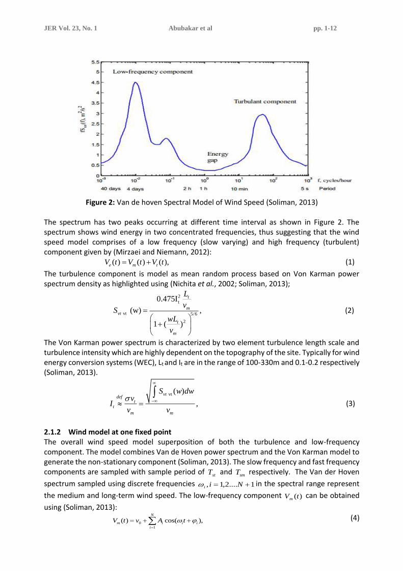
Figure 2: Van de hoven Spectral Model of Wind Speed (Soliman, 2013)
The spectrum has two peaks occurring at different time interval as shown in Figure 2. The spectrum shows wind energy in two concentrated frequencies, thus suggesting that the wind speed model comprises of a low frequency (slow varying) and high frequency (turbulent) component given by (Mirzaei and Niemann, 2012):
( ) ( ) ( ),e m tV t V t V t= + (1)
The turbulence component is model as mean random process based on Von Karman power spectrum density as highlighted using (Nichita et al., 2002; Soliman, 2013);
2
t
vt 5/6
2
0.475I
(w) ,
1 ( )
t
mvt
t
m
L
vS
wL
v
=
+
(2)
The Von Karman power spectrum is characterized by two element turbulence length scale and turbulence intensity which are highly dependent on the topography of the site. Typically for wind energy conversion systems (WEC), Lt and It are in the range of 100-330m and 0.1-0.2 respectively (Soliman, 2013).
vt ( )
,
vtdef
tt
m m
S w dwv
Iv v
− =
(3)
2.1.2 Wind model at one fixed point The overall wind speed model superposition of both the turbulence and low-frequency component. The model combines Van de Hoven power spectrum and the Von Karman model to generate the non-stationary component (Soliman, 2013). The slow frequency and fast frequency components are sampled with sample period of
stT and smT respectively. The Van der Hoven
spectrum sampled using discrete frequencies 1....2,1, += Nii in the spectral range represent
the medium and long-term wind speed. The low-frequency component )(tVm can be obtained
using (Soliman, 2013):
0
1
( ) cos( ,)N
m i i i
i
V t v A t =
= + + (4)

JER Vol. 23, No. 1 Abubakar et al pp. 1-12
1 1
2 1( ( ) ( )).( ),
2i vv i vv i i iA S S
+ += + − (5)
To determine the turbulence component, a unit variance white noise is filter using the rational shaping filter HF (s) combines with parameters TF and KF given by (Nichita et al., 2002; Soliman, 2013):
.)125.0)(1(
)14.0(
++
+=
sTsT
sTKH
FF
FFF
(6)
m
Fv
LT
. (7)
FF TK 71138.0= . (8)
2.1.3 Wind speed capture at the blade The wind turbine blade rotates in a three-dimensional wind speed field, thus making the wind speed spatial distribution over the rotor area from being uniform. In addition, the magnitude of both the mean wind speed and the turbulence component can vary significantly from one point to another. The wind speed variation experience on the rotating blade element can be classified either as deterministic or stochastic variations (Soliman, 2013). The wind shear and the tower shadows are the main causes of deterministic variation, whilst the spatial variations on the turbulence component at the different point are the cause of stochastic variations. The effects of the wind shear, tower effect and spatial variation are model to obtained an effective wind speed model as contained in the work of (Soliman, 2013) (Petru and Thiringer, 2002). 2.2 Overall Model of VSVP Wind Turbine System The dynamic model of the of the system can be obtained by combining torque and pitch actuator system, aerodynamic subsystem, shaft model, tower and generator model as shown in Figure 1.0. Whilst, the overall model is like the model developed in the work of (Bianchi et al. 2006; Jespersen & Krogen, 2011). The state space of the combine subsystem can be represented using (Jespersen & Krogen, 2011):
( )
( )
+
−
−
−
−−
−
−+−
−
+−
=
•
•
•
••
•
•
•
•
v
T
v
F
m
v
T
H
T
Y
Y
T
F
mv
F
mm
B
m
kF
m
kk
HHH
DD
H
D
T
Hv
T
HHH
DT
HH
DD
T
Y
Y
T
gref
ref
g
vr
t
vr
t
g
t
t
tg
g
r
g
r
t
vr
tt
t
t
t
r
r
t
tgtg
ggg
gtg
g
tg
r
t
vr
ttt
tg
r
r
tt
gtg
g
t
t
tg
g
r
r
r
01
0
001
100
000
000
000
2
100
1000000
01
00000
011
001
0001000
00000
2
1000
2
1
22
02
1
2
10
2
1
22
1
2
0
0
000
000
.
(9)
The output matrix can be obtained by combining all the state of variable to form the output matrix given by:

JER Vol. 23, No. 1 Abubakar et al pp. 1-12
+
=
•
•
v
T
T
Y
Y
T
TP
T
Y
Y
T
gref
ref
g
t
t
tg
g
r
ggggg
g
t
t
tg
g
r
000
000
000
000
000
000
000
000
00000
1000000
0100000
0010000
0001000
0000100
0000010
0000001
00 .
(10)
For design purpose, it is important to use model that captures the relevant dynamics of the system, because the electrical dynamics of the subsystem are much faster as compared to mechanical dynamic. The effect of the movement of tower due to the influence of wind speed seen by the rotor is neglected (Soliman et al., 2011). The linear state space model representing
the relevant dynamics of the WEC system at a certain operating wind speed ( 0v ) is given by:
( ) ( ) vvuxvX vum 00 ++=•
. (11)
where:
=m
( )
( )
0 0
1 1 1
2 2 2 2 2
1 1
2 2 2 2
1
0
0
0 0 0
0 0 0 0
0 0 01
0
r
tg g tgr r
t t r t t t
tg gtg
g g g g
tg tg
g
D D DT T
H H H H H
D DD
H H H H
k k
− + −
− + −
−
−
−
.
(12)
=
g
u
1
0
01
00
00
00
. (13)
=
0
0
0
0
2
10v
r
g
v
v
T
H
. (14)
=
00 000
00010
ggggTC
. (15)
The matrices 5RTTT
gtggr represent the state matrix, while the
2RTT
grefref is the control input and 2RPT
gg is the measured output matrix. The

JER Vol. 23, No. 1 Abubakar et al pp. 1-12
parameters in the linearized matrices are like the parameters adopted by the work of Soliman (2013). 2.3 Formulation of the Problem The optimization problem takes the predicted controlled output from the prediction model bank and finds the optimal input changes so that the predicted output is driven towards the reference. The controller solves the optimization problem given by:
=
−
=
++++=PN
1k
1
0
22i )()(y-k)r(t
c
ii
N
kRQ
ktuktMinJ (16)
Subjected to: maxmin )( uktuu + , (17)
c( ) 0 k 0,1.....N 1u t k + = = − , (18)
pmax 1,2......Nk ,)( =+ ykty i
. (19)
r is the reference vector defined as )()()( ** tPttr gg= and )(tu is defined as )1()( −− tutu .
While the vectors minmax ,uu and maxy are defined as follows:
Ti
ref
i
grefg TTu ] [ maxmaxmax −−=, (20)
Ti
ref
i
grefTu ] [ minmin −−= , (21)
Ti
g
i
gg pPy ] [ gmaxmaxmax −−= . (22)
2.4 Design of Baseline Controller The baseline controller comprises torque and pitch controller controlled via two independent PI controllers (Jonkman et al., 2009). The two proportional Integral controllers which adjusts and regulate the generator speed at both low and high-speed regime. Whose transfer function is given Equation (23). The proportional and integral gains
pK and iK is tuned using PIDtune
command in MATLAB which was used to obtained the gain at different operating wind speed. At low speed or partial load regime, the pitch angle ( ) is fixed at zero and the generator torque (
gT ) is manipulated by the first PI controller using Equation (24) so that the generator speed (g
) track the desire generator speed set point, thus ensuring the torque is within its stated limit. Whilst at high-speed or full load regime, the torque (
gT ) is fixed at its rated value gratT , the pitch
angle ( ) is manipulated by the second PI controller so as to regulate the speed and power
produced by the generator using Equation (25). This work adopt a baseline controller similar to the work of (Soliman et al, 2011) as shown in Figure 3.
( ) ip
KG s K
s= +
, (23)
( ) ig p grat g
KT K
s
= + −
, (24)
( )ip grat g
KK
s
= + −
, (25)
where grat and g represent the rated and operating speed of the generator respectively.

JER Vol. 23, No. 1 Abubakar et al pp. 1-12
Reference
Generator
PI
WEC
PI
β =0
Tgrat
v
βref
Tgref
ωg
Low/high speed regime
ωg
-
+
Pitch controller
Torque Controller
Figure 3: Baseline Controller of the Wind Energy Conversion System 2.5 Design of Multiple Model Predictive Controller The MMPC comprises of multiple predictive control (MPC). The controller is designed using the linearized model bank obtained using the operating wind speed ranging from 0-26m/s. The weighted parameter of the model predictive control iQ and iR are selected based on the wind
turbine operating mode. The controllers are gain scheduled and switched based on the operating wind speed to form a multiple model predictive control system. In low-speed regime,
iR is selected in a manner that the pitch angle is set to zero, so as to achieved the desired tracking. During high-speed regime iQ should be set to zero to allow the pitch angle take any
required value. The MMPC was implemented using default MPC in Simulink and the parametersiQ and iR based on the operating mode. A state estimation model based on default Kalman filter
was used to estimate the state of the system. The block diagram of the proposed MMPC is shown in Figure 4.
WECS
Optimization
Linearized Model
Bank
Multiple Model
Predictive Control
State Estimation
WECS
Pg
ωg
StateSpace matrices
βref
Tgref
Pg
ωg
v
Scheduling Signal
Effective wind
Speed Model
Figure 4: Proposed MMPC Controller of the Wind Energy Conversion System

JER Vol. 23, No. 1 Abubakar et al pp. 1-12
The developed multiple model predictive controller is simulated with a predicted horizon of
30=pN and control horizon 10=cN with different operating wind speed corresponding to low
and high- speed regime. Also, the parameters of the 1.5MW GE DFIG is like the work of Soliman (2013). 3.0 RESULTS AND DISCUSSION The MMPC and PI are subjected to an effective wind speed (realistic wind speed) for 600s during low and high- speed regime. 3.1 Response at Low-Speed Regime The controllers were tested using a mean wind speed of 6m/s, the effective wind speed obtained is as shown in Figure 5a. The performances of both controllers were compared under fluctuating wind speed models. Figure 5c shows the variation of the torque due to variation in wind speed. The torque fluctuates for both controllers (PI and MMPC) due to abrupt change in the wind speed. The generator speed for both controller fluctuate with slight variation resulting from fluctuation in wind speed as seen in Figure 5d.
(a) Wind speed (c) Generator Torque
(b) Generator speed (d) Generator Power
Figure 5: (a),(b),(c) and (d): Response Due to Stochastic Wind Speed for Both Controllers at Low-speed Regime
Based on the results obtained it can be observed that in both controllers, the generator power was lower than the rated power of the wind turbine system due to fluctuation in the generator

JER Vol. 23, No. 1 Abubakar et al pp. 1-12
speed as shown in Figures 5b and 5d. The developed MMPC recorded a reduced drive train of 8.6364 rad/s as compared to 11,1317 rad/s for the PI controller. Also, with a reduced flicker emission of 341.9537W as compared to the standard PI controller of value 384.3928W. 3.2 Response at High-Speed Regime The controllers were tested using a mean wind speed of 16m/s corresponding to high speed regime, the effective wind speed is as shown in Figure 6a. Both controllers were subjected to this effective wind speed. Figure 6c shows the variation in the pitch angle due to fluctuation in the wind speed. The pitch angle of the MMPC controller is faster as compared to the PI controller, while that of PI experience a slight delay of 50s as seen in Figure 6c. The generator speed and power maintain a constant value with slight variation due to fluctuating wind speed as shown in Figure 6b and 6d.
(a) Wind speed (c) Generator Torque
(b) Generator speed (d) Generator Power
Figure 6: (a),(b),(c) and (d): Response Due to Stochastic Wind Speed for Both Controllers at high-speed regime
The developed MMPC offers a reduction in drive train load of 0.8456 rad/s as compared to 2.4290 rad/s for the PI controller as shown in Figure (11). While, the MMPC outperforms the PI with a reduction in flicker emission of 159.8086W as compared to standard PI controller of value 125.4010W as shown in Figure (6d).

JER Vol. 23, No. 1 Abubakar et al pp. 1-12
3.3 Comparison of Both Controllers The performance indices were computed using flicker emission and drive train for both MMPC and PI controller at low/high speed regime. The summary of the results is as contained in Table 1.
Table 1: Comparison Between MMPC and PI Controller
Low speed Regime (6m/s) High speed Regime (16m/s)
Test MMPC PI MMPC PI P(W) 0.000025131 0.000024068 0.0000014661 0.0000014216 P(W) 0.0006263 0.0007040 0.007956 0.0002296 P(%) Del 48.6653 54.0752 1.1167 3.2236
)/( sradg 102.9397 98.3214 155.0514 150.3362
)/( sradg 8.6364 11.1317 0.8456 2.4290
(%) gDel 16.782 21.6369 1.1214 3.2236
Based on the Table 1.0 a reduction of 11.04% and 22.42% in flicker emission and drive train load was obtained for the MMPC as compared to PI controller of 0.540752 and 0.216369 respectively at low speed regime (mean speed of 6m/s). while at high speed regime (16m/s) the MMPC recorded a reduction in flicker emission and drive train load of 65.36% and 65.21% respectively as compared to PI controller of 0.032236 and 0.032236 respectively. The performance of the MMPC outperforms the standard PI in tracking the desire set points using realistic wind speed model with a reduction in both flicker emission and drive train load.
4. CONCLUSION This work developed a multiple model predictive control scheme for a doubly fed induction generator-based wind energy conversion system. A stationary wind speed model was developed using Van de Hoven and Von Karman power spectrum. A non-stationary or effective wind speed model was developed using rotational sampling filter to determine the effective wind speed at both low (6m/s) and high-speed regimes (16m/s) respectively. The gain scheduled PI and multiple model predictive control scheme was developed for different operating wind speed. The performance of both controllers was tested and implemented via simulation on a standard 1.5MW General Electric wind turbine system. The performance of the MMPC outperforms the gain scheduled PI in tracking the desire set points and reduction in both damping torque and power oscillation using realistic wind speed model with a reduction in both flicker emission and drive train load. REFERENCES Alfeu Filho, and de Oliveira Filho. (2011). A predictive power control for wind energy. Sustainable Energy, IEEE
Transactions on, 2(1), 97-105. Bemporad. (2006). Model predictive control design: New trends and tools. Paper presented at the Proceedings of
the 45th IEEE Conference on Decision and Control, 23(1), 2 Blaabjerg, Ma. (2013). Future on Power Electronics for Wind Turbine System. IEEE JOURNAL OF EMERGING AND
SELECTED TOPICS IN POWER ELECTRONICS, 1(3), 139-152. doi:10.1109?JESTPE.2013.2275978 Camacho, Samad, Garcia-Sanz, & Hiskens. (2011). Control for Renewable Energy and Smart Grids. Impact of Control
Technology. doi:http://ieeecss.org/main/ioCT-report Evans, Cannon, and Kouvaritakis. (2015). Robust MPC tower damping for variable speed wind turbines. IEEE
Transactions on Control Systems Technology, 23(1), 290-296. Ezzat, Benbouzid, Muyeen, & Harnefors. (2013). Low-voltage ride-through techniques for DFIG-based wind turbines:
state-of-the-art review and future trends. Paper presented at the Industrial Electronics Society, IECON 2013-39th Annual Conference of the IEEE.

JER Vol. 23, No. 1 Abubakar et al pp. 1-12
Jonkman, Butterfield, Musial, & Scott. (2009). Definition of a 5-MW reference wind turbine for offshore system development.
Kaneko, Hara, and Konishi. (2012). Model predictive control of DFIG-based wind turbines. Paper presented at the 2012 American Control Conference (ACC).
Liu, and Kong. (2014a). Nonlinear model predictive control for DFIG-based wind power generation. IEEE Transactions on Automation Science and Engineering, 11(4), 1046-1055.
Liu, and Kong. (2014b). Nonlinear Model Predictive Control for DFIG-Based Wind Power Generation. IEEE Transactions on Automation Science and Engineering, 11(4), 1047-1055. doi:10.1109/TASE.2013.2284066
Liu, Zhac, Zhang, Zhu, and Chen. (2014). Simulation Study on Transient Characteristic of DFIG Wind Turbine Systems Based on Dynamic Modeling. China International Conference on Electricity Distribution (CICED 2014), 1(6), 1408, 1409, 1410.
Marian P Kazmierkowski, Jasinski, and Wrona. (2011). DSP-Based Control of Grid-Connected Power Converter Operating Under Grid Distortions. IEEE TRANSACTIONS ON INDUSTRIAL INFORMATICS, 7(2), 204-211. doi:10.1109?TH.2011.2134856
Martinez, Susperregui, Tapia, and Xu. (2013). Sliding-mode control of a wind turbine-driven double-fed induction generator under non-ideal grid voltages. Renewable Power Generation, IET, 7(4), 370-379.
Mirzaei, Kj, & Niemann. (2012). Robust model predictive control of a wind turbine. Paper presented at the 2012 American Control Conference (ACC).
Mishra, Mishra, Li, and Dong. (2009). TS-fuzzy controlled DFIG based wind energy conversion systems. Paper presented at the Power & Energy Society General Meeting, 2009. PES'09. IEEE.
Nichita, Luca, Dakyo, and Ceanga. (2002). Large Band Simulation of the wind Speed for Real Time Wind Turbine Simulators. IEEE TRANSACTIONON ENERGY CONVERSION, 523-529.
Orlando, Liserre, Mastromauro, and Aquila. (2013). A Survey of control Issues in PMSG-Based Small Wind turbine systems. IEEE TRANSACTION ON INDUSTRIES AND INFORMATICS, 9(3), 1211-1221. doi:10.1109/TH.2013.2272888
Pati, and Samantray. (2014). Decoupled control of active and reactive power in a DFIG based wind energy conversion system with conventional PI controllers. Paper presented at the Circuit, Power and Computing Technologies (ICCPCT), 2014 International Conference on.
Petru, and Thiringer. (2002). Modeling of wind turbines for power system studies. IEEE transactions on Power Systems, 17(4), 1132-1139.
Si, and Liu. (2015). Model predictive control for DFIG-based wind power generation under unbalanced network conditions. Paper presented at the Control Conference (CCC), 2015 34th Chinese.
Soliman. (2013). Model predictive control of DFIG-based wind power generation systems. University of Calgary, 1-240
Soliman, Malik, and Westwick. (2011). Multiple model predictive control for wind turbines with doubly fed induction generators. IEEE Transactions on Sustainable Energy, 2(3), 215-225.
Susperregui, .M, G, and Vechiu. (2013). Second-Order Sliding-Mode Controller Design and Tuning for Grid Synchronization and Power Control of a Wind Turbine-driven Doubly Fed Induction Generator. Institute of Engineering and Technology Renewable Power Generation, 7(5), 540-551. doi:doi:10.1049/iet-rpg.2012.0026
Xibo, Fred, Rolando, Yongdong, and Dushan. (2008). DC-link Voltage Control of Full Power Converter for Wind Generator Operating in a weak Grid. IEEE, 9(8), 761-767.