Development of a Lobster-Inspired Underwater...
15
International Journal of Advanced Robotic Systems Development of a Lobster-Inspired Underwater Microrobot Regular Paper Liwei Shi 1,2,* , Shuxiang Guo 1,2 , Shilian Mao 3 , Maoxun Li 3 and Kinji Asaka 4 1 Faculty of Engineering, Kagawa University, Takamatsu, Kagawa, Japan 2 School of Life Science, Beijing Institute of Technology, Haidian District, Beijing, China 3 Graduate School of Engineering, Kagawa University, Takamatsu, Japan 4 Kansai Research Institute, AIST, Ikeda, Osaka, Japan * Corresponding author E-mail: [email protected] Received 4 Sep 2012; Accepted 5 Nov 2012 DOI: 10.5772/54868 © 2013 Shi et al.; licensee InTech. This is an open access article distributed under the terms of the Creative Commons Attribution License (http://creativecommons.org/licenses/by/3.0), which permits unrestricted use, distribution, and reproduction in any medium, provided the original work is properly cited. Abstract Biomimetic underwater microrobots are of great interest for underwater monitoring operations, such as pollution detection and video mapping in restricted underwater environments. Generally speaking, compact structure, multi‐functionality, flexibility and precise positioning are considered incompatible characteristics for underwater microrobots. Nevertheless, we have designed several novel types of bio‐inspired locomotion, using ionic polymer metal composite (IPMC) and shape memory alloy (SMA) actuators. We reviewed a number of previously developed underwater microrobot prototypes that were constructed to demonstrate the feasibility of these types of biomimetic locomotion. Based on these prototypes, we summarized the implemented techniques and available results for efficient and precise underwater locomotion. In order to combine compact structure, multi‐functionality, flexibility and precise positioning, we constructed a prototype of a new lobster‐like microrobot and carried out a series of experiments to evaluate its walking, rotating, floating and grasping motions. Diving/surfacing experiments were performed by electrolyzing the water around the surfaces of the actuators. Three proximity sensors were installed on the microrobot to detect an object or avoid an obstacle while walking. Keywords Ionic Polymer Metal Composite (IPMC) Actuators, Biomimetic Underwater Microrobot, Micromechanism 1. Introduction Robots have been used to carry out a wide range of underwater jobs that humans deem dangerous, dull and/or dirty, mostly because of their aptitude for multi‐ functionality and high accuracy. This trend has continued into underwater monitoring operations, including pollution detection, video mapping, exploration of unstructured underwater environments and other tasks [1, 2]. Various configurations, shapes and sizes of underwater robots are required for different applications or tasks. For underwater environmental detection or observation, a compact structure with multi‐functionality and flexibility enables a robot to work in limited spaces. When a large range of motions and large load capacity are required, a traditional motor‐actuated electromagnetic structure is essential. When large interior space and flexible multidirectional rotation in a restricted space are required, a spherical robot body is recommended. When high‐speed 1 ARTICLE www.intechopen.com Int J Adv Robotic Sy, 2013, Vol. 10, 44:2013
Transcript of Development of a Lobster-Inspired Underwater...

International Journal of Advanced Robotic Systems Development of a Lobster-Inspired Underwater Microrobot Regular Paper
Liwei Shi1,2,*, Shuxiang Guo1,2, Shilian Mao3, Maoxun Li3 and Kinji Asaka4
1 Faculty of Engineering, Kagawa University, Takamatsu, Kagawa, Japan 2 School of Life Science, Beijing Institute of Technology, Haidian District, Beijing, China 3 Graduate School of Engineering, Kagawa University, Takamatsu, Japan 4 Kansai Research Institute, AIST, Ikeda, Osaka, Japan * Corresponding author E-mail: [email protected]
Received 4 Sep 2012; Accepted 5 Nov 2012 DOI: 10.5772/54868 © 2013 Shi et al.; licensee InTech. This is an open access article distributed under the terms of the Creative Commons Attribution License (http://creativecommons.org/licenses/by/3.0), which permits unrestricted use, distribution, and reproduction in any medium, provided the original work is properly cited.
Abstract Biomimetic underwater microrobots are of great interest for underwater monitoring operations, such as pollution detection and video mapping in restricted underwater environments. Generally speaking, compact structure, multi‐functionality, flexibility and precise positioning are considered incompatible characteristics for underwater microrobots. Nevertheless, we have designed several novel types of bio‐inspired locomotion, using ionic polymer metal composite (IPMC) and shape memory alloy (SMA) actuators. We reviewed a number of previously developed underwater microrobot prototypes that were constructed to demonstrate the feasibility of these types of biomimetic locomotion. Based on these prototypes, we summarized the implemented techniques and available results for efficient and precise underwater locomotion. In order to combine compact structure, multi‐functionality, flexibility and precise positioning, we constructed a prototype of a new lobster‐like microrobot and carried out a series of experiments to evaluate its walking, rotating, floating and grasping motions. Diving/surfacing experiments were performed by electrolyzing the water around the surfaces of the actuators. Three proximity sensors were installed on the microrobot to detect an object or avoid an obstacle while walking.
Keywords Ionic Polymer Metal Composite (IPMC) Actuators, Biomimetic Underwater Microrobot, Micromechanism
1. Introduction
Robots have been used to carry out a wide range of underwater jobs that humans deem dangerous, dull and/or dirty, mostly because of their aptitude for multi‐functionality and high accuracy. This trend has continued into underwater monitoring operations, including pollution detection, video mapping, exploration of unstructured underwater environments and other tasks [1, 2]. Various configurations, shapes and sizes of underwater robots are required for different applications or tasks. For underwater environmental detection or observation, a compact structure with multi‐functionality and flexibility enables a robot to work in limited spaces. When a large range of motions and large load capacity are required, a traditional motor‐actuated electromagnetic structure is essential. When large interior space and flexible multidirectional rotation in a restricted space are required, a spherical robot body is recommended. When high‐speed
1Liwei Shi, Shuxiang Guo, Shilian Mao, Maoxun Li and Kinji Asaka: Development of a Lobster-Inspired Underwater Microrobot
www.intechopen.com
ARTICLE
www.intechopen.com Int J Adv Robotic Sy, 2013, Vol. 10, 44:2013

cruising is required, a streamlined robot body may be the best choice [3]. If a robot is to be used in a complicated underwater environment, such as a narrow pipeline or a region filled with reefs, it should be endowed with the combined attributes of endurance, stable high speed, large load capability, flexibility, compact structure and multi‐functionality. Many types of underwater robots have been developed in recent years. While the use of some of these robots involves changing the angles of rudders or adjusting the differential propulsive forces of thrusters, a number of vectored propeller‐actuated underwater robots have also been introduced [4]. A multi‐channel Hall‐effect thruster has also been reported, involving vector composition of underwater robots [5]. Moreover, we have developed a spherical underwater robot equipped with three vectored water‐jet‐based thrusters [3]. However, most of these robots are steered by traditional electromagnetic thrusters, which are difficult to miniaturize. Accordingly, motors are rarely found in microrobot applications [6, 7] and special actuator materials are used instead. A variety of smart materials, such as ionic polymer metal composite (IPMC), piezoelectric elements, pneumatic actuators and shape memory alloy, have been investigated for use as artificial muscles in new types of microrobots [8–14]. In this research, IPMC is used as actuator material to develop a microrobot with a compact structure, multi‐functionality and flexibility. The actuation characteristics of IPMC, which include suitable response time, high bending deformation and long life, show significant potential for the propulsion of underwater microrobots [15–20]. For real‐world applications, an underwater robot should possess the attributes of endurance, stable high speed, large load capacity, flexibility, compact structure and multi‐functionality. To implement these characteristics, we propose a mother–son robot system, which includes several microrobots as sons and a newly designed amphibious spherical robot as the mother. This is an original concept and is inspired by the design of aircraft carrier systems. In this system, the mother robot is actuated by four water‐jet propellers and eight servomotors, capable of providing a stable high speed and carrying the microrobots to a desired target location where tasks are to be performed. When the mother robot reaches the desired location, or encounters a narrow channel that is difficult to navigate, it assumes a stable position and acts as a base station for the microrobots. Then, the microrobots exit the mother robot, proceed to the target position and carry out their tasks. Compared with a single large robot, when the final tasks are carried out by microrobots, it is easier to adapt to
narrow environments and implement relatively high positioning precision. In addition, compared with individual microrobots, the mother–son system offers the following advantages. 1. The range of motions of the overall system is
expanded, owing to the relatively high speed and endurance of the mother robot.
2. The microrobots can obtain a relatively stable, high power supply via cables.
3. Since the microrobots are all controlled by the mother robot, communications between microrobots can be implemented by the mother when cooperation is needed.
4. Since the power supply and control units are installed in the mother robot, the microrobots can be designed with a more compact structure, suitable for restricted spaces such as narrow pipelines or channels.
We introduced a newly designed spherical amphibious mother robot in [21] and [22]. A spherical body has both a compact structure and maximum interior space, compared to a streamlined body. It can rotate and change direction more easily than a streamlined design, which is very important for microrobots in restricted spaces. To expand the range of motion of the overall system, we designed the mother robot for amphibious use. In this paper, we will mainly focus on the microrobots. Nature provides the best models for robots. Living creatures furnish an abundance of structures for biomimetic robot design. Aside from fish‐like and manta‐ray‐like swimming locomotion, we have developed several microrobots that employ biomimetic locomotion to implement walking, floating and swimming motions [1, 2, 23–26]. However, each of these units implements only some of these motions and none of them are able to carry out simple tasks such as grasping and carrying objects to a desired position, detecting an object, or avoiding an obstacle. In order to create a compact structure with efficient and precise locomotion, and multi‐functionality, we have developed a new microrobot with nine IPMC actuators, used as legs or fingers. This unit employs seven of its actuators to walk, rotate and float. The other two actuators are utilized to implement grasping. Moreover, the microrobot can detect the direction and distance of an object, and avoid an obstacle while walking, using three infrared proximity sensors. In this paper, the ‘multifunctional locomotion’ means that the microrobot can perform walking, rotating, grasping and surfacing/diving motions. However, the term ‘multi‐functionality’ means not only implementing these motions, but also carrying out simple tasks such as grasping and carrying objects to a desired position, detecting an object, or avoiding an obstacle.
2 Int J Adv Robotic Sy, 2013, Vol. 10, 44:2013 www.intechopen.com
The remainder of this paper is divided into four parts. First, we describe the characteristics of IPMC actuators, review the feasibility results for several previously developed microrobots and summarize the implemented techniques of underwater locomotion, as a guide to the next stage of microrobot design. Second, based on these techniques of biomimetic locomotion, we introduce a new type of microrobot with a compact structure and multi‐functional locomotion, analyse its walking mechanism, and calculate its theoretical walking speed. Third, we discuss the development of a prototype of this underwater microrobot, together with a series of experiments to evaluate its walking and rotating speeds on a flat underwater surface. We also describe object detection and obstacle avoidance while walking, which is accomplished via three proximity sensors installed in the front of the microrobot. Finally, we present our conclusions.
2. Biomimetic locomotion
2.1 IPMC actuators
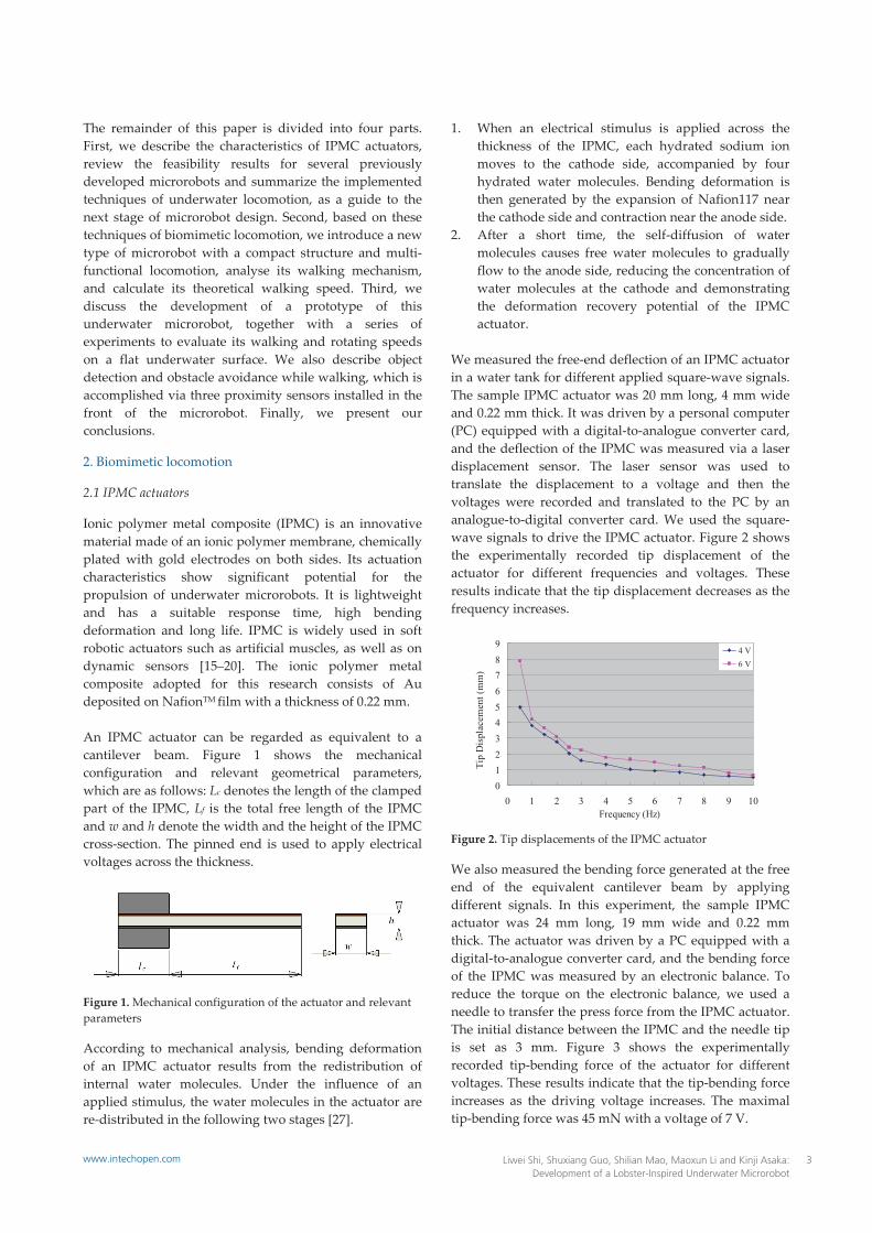
Ionic polymer metal composite (IPMC) is an innovative material made of an ionic polymer membrane, chemically plated with gold electrodes on both sides. Its actuation characteristics show significant potential for the propulsion of underwater microrobots. It is lightweight and has a suitable response time, high bending deformation and long life. IPMC is widely used in soft robotic actuators such as artificial muscles, as well as on dynamic sensors [15–20]. The ionic polymer metal composite adopted for this research consists of Au deposited on NafionTM film with a thickness of 0.22 mm. An IPMC actuator can be regarded as equivalent to a cantilever beam. Figure 1 shows the mechanical configuration and relevant geometrical parameters, which are as follows: Lc denotes the length of the clamped part of the IPMC, Lf is the total free length of the IPMC and w and h denote the width and the height of the IPMC cross‐section. The pinned end is used to apply electrical voltages across the thickness.
Figure 1. Mechanical configuration of the actuator and relevant parameters
According to mechanical analysis, bending deformation of an IPMC actuator results from the redistribution of internal water molecules. Under the influence of an applied stimulus, the water molecules in the actuator are re‐distributed in the following two stages [27].
1. When an electrical stimulus is applied across the thickness of the IPMC, each hydrated sodium ion moves to the cathode side, accompanied by four hydrated water molecules. Bending deformation is then generated by the expansion of Nafion117 near the cathode side and contraction near the anode side.
2. After a short time, the self‐diffusion of water molecules causes free water molecules to gradually flow to the anode side, reducing the concentration of water molecules at the cathode and demonstrating the deformation recovery potential of the IPMC actuator.
We measured the free‐end deflection of an IPMC actuator in a water tank for different applied square‐wave signals. The sample IPMC actuator was 20 mm long, 4 mm wide and 0.22 mm thick. It was driven by a personal computer (PC) equipped with a digital‐to‐analogue converter card, and the deflection of the IPMC was measured via a laser displacement sensor. The laser sensor was used to translate the displacement to a voltage and then the voltages were recorded and translated to the PC by an analogue‐to‐digital converter card. We used the square‐wave signals to drive the IPMC actuator. Figure 2 shows the experimentally recorded tip displacement of the actuator for different frequencies and voltages. These results indicate that the tip displacement decreases as the frequency increases.
Figure 2. Tip displacements of the IPMC actuator
We also measured the bending force generated at the free end of the equivalent cantilever beam by applying different signals. In this experiment, the sample IPMC actuator was 24 mm long, 19 mm wide and 0.22 mm thick. The actuator was driven by a PC equipped with a digital‐to‐analogue converter card, and the bending force of the IPMC was measured by an electronic balance. To reduce the torque on the electronic balance, we used a needle to transfer the press force from the IPMC actuator. The initial distance between the IPMC and the needle tip is set as 3 mm. Figure 3 shows the experimentally recorded tip‐bending force of the actuator for different voltages. These results indicate that the tip‐bending force increases as the driving voltage increases. The maximal tip‐bending force was 45 mN with a voltage of 7 V.
0123456789
0 1 2 3 4 5 6 7 8 9 10Frequency (Hz)
Tip
Dis
plac
emen
t (m
m)
4 V6 V
3Liwei Shi, Shuxiang Guo, Shilian Mao, Maoxun Li and Kinji Asaka: Development of a Lobster-Inspired Underwater Microrobot
www.intechopen.com

2.2 Bio‐inspired locomotion
IPMC actuators can be used as oscillating or undulating fins for swimming microrobots when a fast response is required [15–17, 28, 29]. However, this type of swimming motion cannot ensure precise positioning of the robot. Fish‐like robots cannot implement a backward swimming motion, which is essential in a restricted space. Furthermore, fish‐like propulsion mechanisms simply mimic the undulating and oscillatory body/fin motions of a fish. Some simple underwater tasks are not easily carried out without hands or fingers. Therefore, in addition to swimming, other types of biomimetic locomotion are required for microrobots with compact structure, multi‐functions and flexibility.
Figure 3. Bending forces of the IPMC actuator
2.2.1 Stick insect‐inspired walking locomotion
Nature provides perfect models for robots. Biomimetic robots borrow their senses and structure from animals, such as insects, fish and birds. In the case of the stick insect, each leg is composed of the coxa, femur, tibiae and tarsus. The tarsus is also called the foot and does not contribute to its movements. The coxa offers the foot one degree of freedom (DOF) in the direction of movement. The femur and the tibiae offer the foot two DOF to enable it to find a reliable foothold during the swing–search phase to touch the ground and support the body during the stance phase.
Figure 4. Two‐phase driving locomotion with IPMC actuators [24]
A stick insect‐inspired biomimetic locomotion prototype using two IPMC actuators was introduced in [1]. As Fig. 4 shows, the actuator in the vertical direction is called the
driver, while the actuator in the horizontal direction is called the supporter. The free end of the driver is the foot. The driver and supporter are controlled by two channels of square waves, each with the same frequency. The phase of the supporter lags 90 degrees behind that of the driver [1, 2, 24].
2.2.2 Jellyfish‐like floating locomotion
Jellyfish movement is dependent on floatation, ocean currents and winds, and is accomplished via a form of jet propulsion. Specifically, jellyfishes move by squeezing their bodies so that jets of water are ejected from underneath, propelling them forward. A jellyfish‐inspired biomimetic locomotion prototype with SMA actuators was introduced in [30]. The jellyfish‐inspired body uses SMA actuators to imitate the circular muscles of a real jellyfish. The body shrinks when voltage is applied and water is squeezed out of it. This changes the buoyancy and produces an upward force. The body floats upward when the force reaches a certain value. The upward force can be changed by controlling the frequency of the actuator shrinkage and the voltage between its two ends. This means that the microrobot can be induced to float upward, remain neutrally buoyant, or sink as required.
2.2.3 Inchworm‐inspired crawling locomotion
Inchworms have smooth, hairless bodies, usually about 25 mm long. Also known as measuring worms, spanworms, or loopers, they lack appendages in their midsections, causing them to have a characteristic looping gait. They have three pairs of true legs at the front end, like other caterpillars, but only two or three pairs of prolegs at the rear end. An inchworm moves by drawing its hind end forward while holding on with its front legs, and then advancing its front section while holding on with its prolegs [25, 31, 32]. An inchworm‐inspired biomimetic locomotion prototype with two IPMC actuators was introduced to implement fast creeping. The design was based on a one DOF leg. The structure of the one DOF walking mechanism is described in [32]. This mechanism can only implement crawling motion.
3. Review of previously developed microrobots
Based on stick insect‐inspired walking locomotion, a prototype of an eight‐legged microrobot was developed, as shown in Fig. 5(a) [2]. It was 33 mm long, 56 mm wide and 9 mm high. Four legs were used as drivers and the other four actuators were used as supporters. It was capable of walking, rotating and diving/surfacing. However, the floating efficiency of this microrobot was not high. To improve the floating motion, a prototype of a
0
5
10
15
20
25
30
35
40
45
50
0 1 2 3 4 5 6 7
Voltage (V)
Ben
ding
For
ce (m
N)
4 Int J Adv Robotic Sy, 2013, Vol. 10, 44:2013 www.intechopen.com

jellyfish‐type microrobot was constructed, based on jellyfish‐inspired locomotion, as shown in Fig. 5(b) [1]. It was 68 mm high, with a weight of 4.81 g in air. This biomimetic microrobot consisted of a two‐ring body and four legs. The body was designed to imitate a jellyfish’s diving/surfacing motions. Additionally, four IPMC actuators were fixed on the body to implement walking motion in two directions. Although the floating motion was improved, the prototype was unable to rotate, and the walking motion was unsatisfactory because the centre of gravity was located in one of the two halves of the body, causing an imbalance in the overall body and a large amount of slippage. For the purpose of creating a microrobot with a compact structure and multi‐functions, an inchworm‐inspired microrobot with ten IPMC actuators was developed, as shown in Fig. 5(c). It was 33 mm long, 14 mm wide and 14 mm high. Four outside actuators were used as legs to implement walking, rotating and floating motions. The other six actuators were used as fingers to grasp small objects [25, 32]. Compared with the jellyfish‐like robot, this design offered the advantages of stability, compact structure, less water resistance and grasping motion implementation. However, because the rotating radii were not the same for the outside four legs, a large amount of slippage occurred while rotating and the rotating efficiency was not high. Only the outside four legs were used to electrolyze the water around the IPMC surface, generating air bubbles, which became attached to the surfaces of the legs, increasing the buoyancy and implementing the floating motion. Due to the limitations of the structure, the inside six legs were used solely as fingers to grasp an object and could not contribute any buoyancy to the floating motion, so that the floating speed was slow. To overcome these difficulties, a new lobster‐like microrobot is introduced in the following sections.
4. Proposed multifunctional lobster‐like microrobot
4.1 Actual lobsters
The lobster anatomy includes the cephalothorax, which fuses the head and the thorax, and the abdomen. Lobsters have five pairs of legs, of which the front three pairs have claws and the rear two pairs are used exclusively for walking, as shown in Fig. 6. They live in murky environments at the bottom of the ocean and their heads are equipped with a pair of antennae, which are used as sensors. The abdomen includes small swimmerets, and its tail is composed of uropods and the telson. While walking, the tail also provides some support to the abdomen. In general, lobsters are 25–50 cm long and move by walking slowly across the sea floor. However, when they flee, they swim swiftly backwards by curling and uncurling their abdomens [33].
(a) Stick insect‐inspired [2] (b) Jellyfish‐inspired [1]
(c) Inchworm‐inspired [25, 32]
Figure 5. Prototype microrobots
Figure 6. Actual lobster [34]
4.2 Proposed lobster‐like microrobot
To inherit the multi‐functions of the inchworm‐inspired microrobot and overcome its disadvantages, a new lobster‐like microrobot is proposed. The structure of the new microrobot is shown in Figs. 7 and 8. The microrobot uses nine IPMC actuators as legs or fingers, labelled A to I. Actuators A and B are used as fingers; actuators C, D, E, F, G and H are used as legs; and actuator I is used as a tail, as shown in Fig. 8. The nine actuators are all 14 mm long, 3 mm wide and 0.22 mm thick. The total size of the microrobot is 65 mm long (including the two fingers and the tail), 50 mm wide and 9 mm high.
4.3 Crawling and rotating mechanism
The lobster‐like microrobot employs a two‐phase crawling motion, consisting of a stance phase and a swing–search phase, as with the stick insect. This stick insect‐inspired crawling locomotion was proposed and utilized by Guo et al. in [24]. The details are reiterated here for the sake of clarity. While crawling, legs C and D, and the tail are supporters, while legs E, F, G and H are the drivers. The four drivers and three supporters are driven by square waves with the same frequency, and the phase of the three supporters lags 90° behind that of the four drivers. Each step cycle of the walking motion can then be separated into four periods, as shown in Fig. 9.
5Liwei Shi, Shuxiang Guo, Shilian Mao, Maoxun Li and Kinji Asaka: Development of a Lobster-Inspired Underwater Microrobot
www.intechopen.com

1. The three supporters lift the body up and the drivers are off the ground.
2. While the body is lifted by the three supporters, the four drivers bend forward.
3. The three supporters bend far enough upward so that they are off the ground and the four drivers contact the ground.
4. The four drivers bend backward to push the body forward [1].
Figure 7. Proposed structure of the lobster‐like microrobot
Figure 8. Top view of the microrobot
Figure 9. Crawling mechanism. The ● marks indicate which legs contact the ground.
By changing the bending directions of the drivers on opposite sides of the body, the proposed microrobot can crawl forward or backward and rotate clockwise or counterclockwise, in a manner similar to the slow
crawling motion of an actual lobster on the sea floor. Figure 10 shows one step cycle of the rotational motion, which is also divided into four periods. When the three supporters lift the body upward, the two left drivers bend forward and the two right drivers bend backward. When the three supporters bend upward, the four drivers contact the ground and bend in the reverse direction.
Figure 10. Rotating mechanism. The ● marks indicate which legs contact the ground
The walking and rotating speeds are determined by the displacement of the drivers, and the frequency of the control signal. Since the four drivers are distributed symmetrically on both sides of the body and are fabricated with the same size and deflection characteristics, they bear equivalent loads and drag forces. Therefore, all four drivers provide the same tip displacement for a given applied input voltage. If we denote the tip displacements of the drivers on opposite sides of the body by d1 and d2, respectively, then the walking speed can be obtained from Eq. (1).
0( )v d d f (1)
where v denotes the average speed, d0 denotes the tip displacement of the IPMC actuator without a payload or external forces, Δd is the reduction in the actual displacement of the four drivers due to friction and f is the frequency of the input signal. The rotating speed is determined by the angular displacement of the driver over one cycle and the frequency of the step. Figure 11 (a) shows the angular displacement over one cycle, the blue rectangle represents the initial position of the body and the red rectangle represents the final position after one rotational step. The microrobot can rotate by an angular displacement of θ over one step cycle, as shown in Eq. (2).
2L LR D
(2)
where L denotes the length of the rotating arc, R denotes the radius of the rotating rotundity and D is the diameter, as shown in Figure 11 (a) and Figure 11 (b). The diameter D could be calculated using Eq. (3).
2 2(20 ) (50 2 )D d l (3)
where d denotes the tip displacement of the driver in the stance phase and Δl=ld stands for the displacement decrease of the IPMC actuator, as shown in Eq. (4).
A
B
D
C
F
EG
H
I
IPMC Actuators
6 Int J Adv Robotic Sy, 2013, Vol. 10, 44:2013 www.intechopen.com

d f rl l l (4)
where lf denotes the length of the IPMC actuator, lr and ld are shown in Figure 11 (b). Based on the geometry theorem, we can get the Eq. (5).
AN BN CN DN (5)
(a)
(b)
Figure 11. Angular displacement in one step
From the Figure 11 (b), r is the bending radius of the IPMC actuator, |AN|=|BN|= lr, |DN|=d/2, |CN|=|2r‐d/2|, so lr can be calculated as shown in Eq. (6).
22 2rd dl r (6)
According to Eq. (2), Eq. (3), Eq. (4) and Eq. (6), the device can rotate by an angle of θ in one step cycle, as shown in Eq. (7).
2
2
2 2
(20 ) 50 2 22 2f
L L LR D
d dd l r
(7)
When d is very small, we can approximate the arc L by d. The theoretical rotation speed can then be calculated from Eq. (8).
2
2
2*
(20 ) 50 2 22 2f
df f
d dd l r
(8)
4.4 Floating mechanism
The water around the surface of the IPMC actuators can be electrolyzed when the frequency of the driving voltage is below 0.3 Hz. The proposed microrobot electrolyzes the water around the IPMC surfaces of all six legs. Air bubbles are generated and become attached to the leg surfaces to increase the buoyancy and implement the floating motion. The tail fin is also used to provide buoyancy and to adjust the balance of the overall body while floating. The quantity of air bubbles generated is determined by the frequency and driving voltage. The buoyancy of the microrobot can be controlled by the resulting change in volume to make the microrobot float upward, remain neutrally buoyant, or sink [1].
4.5 Grasping mechanism
We use two IPMC actuators to imitate the front pair of claws of an actual lobster, as shown in Fig. 8. The distance between the pair of claws is 10 mm and they are attached to the front of the microrobot. The generated bending force of the IPMC actuator is determined by the driving voltage and the tip displacement. For a given driving voltage, when the deflection increases, the bending force decreases. Hence, the grasping capability is determined by the size of the object and the coefficient of friction when the stimulus is fixed.
4.6 Control system
Figures 12 and 13 show the control system and amplifier circuit of the microrobot. We use an AVR atmega164 as the control centre of the microrobot, and MOSFET FDS4935A and NDS9936 power sources to drive the IPMC actuator. Legs C–D, E–G and F–H are controlled separately by three square‐wave signals, and tail I is controlled by another square‐wave signal. The claws are stimulated by the same step signal. We use three proximity sensors to judge the direction and distance of an obstacle, and alter its motion accordingly [35].
Figure 12. Control system for the IPMC actuator
7Liwei Shi, Shuxiang Guo, Shilian Mao, Maoxun Li and Kinji Asaka: Development of a Lobster-Inspired Underwater Microrobot
www.intechopen.com

Figure 13. Amplifier circuit
5. Prototype microrobot and experiments
5.1 Prototype of the lobster‐like microrobot
In order to create a compact structure with efficient, precise locomotion and multi‐functionality, we developed a new microrobot with nine IPMC actuators, used as legs or fingers. This unit employs seven of its actuators to walk, rotate and float. The other two actuators are utilized to implement grasping. The prototype is shown in Fig. 14. C, D and I are used as supporters to lift the robot, while E, F, G and H are drivers that bend forward or backward to implement walking and rotation. A and B can be used as two fingers to grasp an object. When floating, I is also used as the tail fin to adjust the balance of the body. Figure 15 shows the proximity sensor used in the present research, which is 8 mm long and 5 mm wide, with a weight of 0.5 g. The distance measurement range for one sensor is from 0 to 60 mm, and the output voltage ranges from 150 mV to the power voltage [35].
5.2 Walking experiments
Lobsters live at the bottom of the ocean, where the seawater is static. They move mostly by walking slowly across the sea floor. Accordingly, to evaluate the walking motion of the new lobster‐like microrobot, we carried out experiments on a flat underwater surface and recorded the time required to crawl a distance of 50 mm with various applied signal voltages and frequencies. Legs C, D, E, F, G and H, and the tail I were used to implement the walking motion. C, D and I were used as supporters, and were driven by a square‐wave voltage. The four drivers E–G and F–H received the same stimulus. The tests were repeated 10 times for each set of control signals, in order to determine the average speed in the same experimental environment. The experimental results are shown in Fig. 16. We can see that: 1) the walking speeds increased when the input voltage increased; 2) with a voltage of 6 V, a maximum walking speed of 6.75 mm/s was attained at 2.5 Hz; and 3) with a voltage of 4 V, a maximum speed of 3.2 mm/s was attained at 4 Hz. A second peak point occurred at 5 Hz with a voltage of 6 V. When the frequency was higher than 10 Hz, the walking speed approached 0. The
maximum operating frequency of the IPMC actuator is about 25 Hz as a simple cantilever in our experiments.
Figure 14. Prototype lobster‐like microrobot
Figure 15. Proximity sensor [35]
Figure 16. Experimental walking speeds
5.3 Rotating experiments
The rotational motion of the microrobot was also examined on a flat underwater surface. We recorded the time required to rotate through an angle of 90° under the influence of various applied signal voltages and frequencies. These tests were also repeated 10 times for each set of control signals, in order to calculate the average speed. The experimental results are shown in Fig. 17. We can see that: 1) the rotating speeds increased when the voltage increased; 2) with a voltage of 6 V, a maximum speed of 10.3°/s was attained at 2 Hz; and 3) with a voltage of 3 V, a maximum speed of 4°/s was
Proximity sensors
IPMC actuators C
D
G
H
E
F
A
B
I
8 Int J Adv Robotic Sy, 2013, Vol. 10, 44:2013 www.intechopen.com

attained at 1.5 Hz. There was also a second peak point at 5 Hz for the rotational speed with a voltage of 6 V. When the frequency was higher than 11 Hz, the rotational speed approached 0. The displacement of the IPMC actuator would be smaller in a real‐world application, due to the body loading, leg slippage and short response time at high frequencies.
Figure 17. Experimental rotating speeds
5.4 Floating experiments
While floating, legs C, D, E, F, G and H are used to electrolyze the water around their surfaces. To avoid permanent deformation of the IPMC actuator, a direct current (DC) stimulus was not utilized. The frequency of the applied voltage ranged from 0.05 Hz to 0.5 Hz with a voltage of 6 V. The experimental environment was the same as that used with the inchworm‐inspired robot. The experimental floating speed results are shown in Fig. 18. The floating speed decreased when the frequency increased. The maximum floating speed was 9.1 mm/s at 0.05 Hz. Compared with the inchworm‐inspired unit, the floating speed of the lobster‐like microrobot was greatly improved. When the frequency was higher than 0.4 Hz, the microrobot was no longer able to float upward.
Figure 18. Experimental floating speeds
5.5 Walking, rotating and hand manipulation experiments
In these tests, first the microrobot walked toward the target object and the pair of claws at the front of the microrobot bent toward each other to grasp the object. Then the microrobot rotated clockwise and walked forward to the desired position while grasping the object. Finally, the microrobot opened its two fingers and walked backward, as shown in Fig. 19.
5.6 Obstacle‐avoidance experiments
Lobsters live in murky environments and their heads are equipped with a pair of antennae, which are used as sensors. To imitate an actual lobster and walk through a relatively complex environment, the microrobot uses three short‐range proximity sensors to detect the direction and distance of an object. The direction and distance of an obstacle can be determined from the output of the three sensors. The microrobot can then alter its motion, either by walking backward, or by rotating clockwise or counterclockwise. An obstacle‐avoidance experiment was also carried out with the inchworm‐inspired microrobot [32, 35]. Due to the low rotating efficiency of this unit and the high installation position of the sensors on top of the body, it was difficult to detect an obstacle with a low profile, and a long time was required to avoid a very wide obstacle. We carried out the obstacle‐avoidance experiments for the lobster‐inspired microrobot on a flat underwater surface (Fig. 20). In these tests, first the microrobot walked toward the obstacle, using legs C to H at a frequency of 1 Hz and an input voltage of 6 V. When the distance between the microrobot and the obstacle decreased to about 20 mm, the three proximity sensors detected the obstacle. The microrobot then stopped and rotated clockwise, continuing until the right, middle and left sensors were successively unable to detect the obstacle. Once this was accomplished, the robot stopped rotating and walked forward. The lobster‐like microrobot implemented underwater walking, rotating, grasping and surfacing/diving motions. As the actual lobster usually crawls at the bottom of the ocean, it isn’t good at swimming, which is just the auxiliary motion while fleeing. So, the developed lobster‐inspired microrobot also had a low swimming efficiency by curling/uncurling its tail part and swinging its four swimmeret‐like drivers to swim.
0
1
2
3
4
5
6
7
8
9
10
0 0.1 0.2 0.3 0.4 0.5
Frequency (Hz)
Floa
ting
Spee
d (m
m/s
)
6 V
9Liwei Shi, Shuxiang Guo, Shilian Mao, Maoxun Li and Kinji Asaka: Development of a Lobster-Inspired Underwater Microrobot
www.intechopen.com

(a) Initial state (b) Walking motion
(c) Opening two fingers (d) Grasping motion
(e) Rotational motion (f) Walking forward
(g) Opening two fingers (h) Walking backward
Figure 19. Walking, rotating and hand manipulation experiment
Object
Object
10 Int J Adv Robotic Sy, 2013, Vol. 10, 44:2013 www.intechopen.com

(a) Initial state (b) Detected the obstacle
(c) Walking backward (d) Rotational motion
(e) Rotating clockwise (f) Rotating clockwise
(g) Walking forward (h) Rotating counterclockwise
Figure 20. Obstacle‐avoidance experiment
Obstacle
Obstacle
11Liwei Shi, Shuxiang Guo, Shilian Mao, Maoxun Li and Kinji Asaka: Development of a Lobster-Inspired Underwater Microrobot
www.intechopen.com

Underwater motions
Implemented methods Actuators Number of actuators
Positionprecision
Flexibility Speeds
Walking motion
Inchworm‐inspired [35] IPMC 2 0.3 mm Adjustable Adjustable
Stick insect‐inspired [2] IPMC 2 0.4 mm Adjustable Adjustable
Lobster‐inspired IPMC 2 0.4 mm Adjustable Adjustable
Floating motion
Electrolysis characteristics of IPMC [35] IPMC 4 No No Adjustable
Jellyfish‐inspired [1, 36‐38] SMA or IPMCSMA (1) or IPMC (6)
No Adjustable Adjustable
Fish bladder‐inspired [29] SMA 1 No No Adjustable
Swimming motion
Fish‐inspired [29] SMA or IPMCSMA (2) or IPMC (1)
No Adjustable Adjustable
Snake‐like [39] IPMC >=2 No No Adjustable
Butterfly‐inspired [26] SMA 2 No Adjustable Fast
Manta ray‐inspired [40] IPMC 8 No Adjustable Adjustable
Grasping motion
Human finger‐inspired [41]
IPMC 3
0.3 mm Adjustable Adjustable
SMA No Inchworm‐inspired [35] IPMC 6 0.3 mm Adjustable Adjustable
Lobster‐inspired IPMC 2 0.2 mm Flexible Adjustable
Table 1. Types of underwater biomimetic locomotion
6. Discussion
In Table 1, we summarize the underwater motions that have been developed for microrobot designs. Three methods of underwater walking have been implemented: inchworm‐inspired, stick insect‐inspired and lobster‐inspired. All of these methods are driven by IPMC actuators and two IPMC actuators are used for one DOF legs. The position precision and flexibility are satisfactory, and the microrobot walking speeds are adjustable. Floating can be achieved through the electrolysis characteristics of IPMC, or through jellyfish‐inspired or fish bladder‐inspired designs. The floating speeds of these three methods are adjustable. However, the position precision and flexibility are not satisfactory, except the flexibility of the jellyfish‐inspired design. Similar to the body and/or caudal fin (BCF), and median and/or paired fin (MPF) type motion in fish classification, robots can be classified into a body and/or caudal actuator (BCA), and median and/or paired actuator (MPA), respectively [42]. Swimming is achieved through fish‐inspired, snake‐inspired, butterfly‐inspired or manta ray‐inspired designs (the first of which has received most attention). Fish‐inspired and snake‐inspired designs are actuated by a body and/or caudal actuator (BCA). Butterfly‐inspired and manta ray‐inspired designs are actuated by a median and/or paired actuator (MPA). The butterfly‐inspired design achieves the fastest swimming speed. The flexibility and swimming speeds of four methods are satisfactory, except the snake‐like design. For the mechanism limitation of oscillatory and the
undulatory motions, none of these four methods can achieve a satisfactory position precision. Human finger‐inspired, inchworm‐inspired and lobster‐inspired finger locomotion have been proposed for grasping, and can be used to grasp and carry some underwater objects. These results can guide us in the design of microrobots with different dimensional and functional requirements.
7. Conclusion
In this paper, stick insect‐inspired two‐phase walking locomotion, jellyfish‐inspired floating/diving locomotion and inchworm‐inspired crawling and grasping locomotion were discussed. The feasibility results for three previously developed prototype microrobots were then reviewed. The floating efficiency of a stick insect‐inspired robot was not high. A jellyfish‐like robot could not rotate and its walking motion was unsatisfactory, although its floating motion was improved. For an inchworm‐inspired robot, there were large differences in the rotational radii of the outside four legs, leading to a large amount of slippage while rotating and low rotating efficiency. In addition, the inside six legs were used solely as fingers to grasp an object and could not contribute any buoyancy to the floating motion, so that the floating speed was slow. To inherit the multi‐functions of the inchworm‐inspired microrobot and overcome its disadvantages, we introduced a new lobster‐like microrobot, intended for underwater exploration in a restricted space. It uses nine IPMC actuators as legs or claws. Seven actuators are used
12 Int J Adv Robotic Sy, 2013, Vol. 10, 44:2013 www.intechopen.com

as legs to implement walking, rotating and floating. The other two actuators are used as claws to grasp small objects. To imitate the antennae of actual lobsters, three infrared proximity sensors are installed on the head of the microrobot to detect an obstacle. We constructed a prototype of this microrobot, carried out experiments and measured the walking and rotating speeds on a flat underwater surface. Compared with the inchworm‐like robot, its rotating motion was greatly improved. Diving/surfacing experiments were also conducted by electrolyzing the water around the actuator surfaces. From the results of these experiments, we demonstrated that the floating efficiency was higher than that of the inchworm‐like robot. By inheriting the grasping motion of the inchworm‐like design, the lobster‐inspired microrobot was also able to grasp small objects while walking or floating. Obstacle‐avoidance experiments were also conducted, using three proximity sensors to detect the direction and distance of an obstacle. Thanks to the low installation position of the sensors and the high rotating efficiency, the lobster‐inspired microrobot was able to detect an obstacle with a low profile and avoid the obstacle to realize closed‐loop control. We have included a summary of the implemented methods of underwater biomimetic locomotion. This can guide us in the design of microrobots with various purposes. Since these methods are driven by low voltages, they are safe and economical, and are suitable for actual applications, such as toys or devices used in an aquarium. As the next step in our research, we will introduce a mother–son robot system to solve microrobot design problems requiring as low speeds and short operating times in restricted operating areas.
8. Acknowledgments
This research is supported by Kagawa University Characteristic Prior Research Fund 2012.
9. References
[1] L. Shi, S. Guo and K. Asaka, “Development of a New Jellyfish‐type Underwater Microrobot”, International Journal of Robotics and Automation, Vol. 26, No.2, pp. 229‐241, 2011.
[2] S. Guo, L. Shi, K. Asaka and L. Li, “Experiments and Characteristics Analysis of a Bio‐inspired Underwater Microrobot”, Proceedings of the 2009 IEEE International Conference on Mechatronics and Automation, pp.3330‐3335, Changchun, China, August 9‐12, 2009.
[3] X. Lin, S. Guo, “Development of a Spherical Underwater Robot Equipped with Multiple Vectored Water‐Jet‐Based Thrusters”, Journal of Intelligent and Robotic Systems, Vol. 67, No. 3‐4, pp. 307‐321, 2012.
[4] E. Cavallo, R. Michelini, V. Filaretov, “Conceptual design of an AUV equipped with a three degrees of freedom vectored thruster”, Journal of Intelligent Robotic Systems, Vol. 39, No.4, pp. 365–391, 2004.
[5] O. Duchemin, A. Lorand, M. Notarianni, D. Valentian, E. Chesta, “Multi‐channel hall‐effect thrusters: mission applications and architecture trade‐offs”, Proceedings of the 30th International Electric Propulsion Conference, pp. 1‐15, Florence, Italy, September 17‐20, 2007.
[6] B. Behkam and M. Sitti, “Design methodology for biomimetic propulsion of miniature swimming robots,” Journal of Dynamic Systems, Measurement and Control, Vol.128, No. 1, pp. 36‐43, 2006.
[7] W. Zhang, S. Guo and K. Asaka, “A New Type of Hybrid Fish‐like Microrobot”, International Journal of Automation and Computing, Vol.3, No.4, pp. 358‐365, 2006.
[8] S. Heo, T. Wiguna, H. Park and N. Goo, “Effect of an artificial caudal fin on the performance of a biomimetic fish robot propelled by piezoelectric actuators”, Journal of Bionic Engineering, Vol. 4, No.3, pp. 151‐158, 2007.
[9] A. Villanueva, K. Joshi, J. Blottman and S. Priya, “A bio‐inspired shape memory alloy composite (BISMAC) actuator”, Smart Materials and Structures, Vol. 19, 025013, pp.1‐17, 2010.
[10] Z. Wang, G. Hang, J. Li, Y. Wang and K. Xiao, “A micro‐robot fish with embedded SMA wire actuated flexible biomimetic fin”, Journal of Sensors and Actuators A: Physical, Vol. 144, No. 2, pp. 354‐360, 2008.
[11] S. Lee, K. Kim and I. Park, “Modeling and experiment of a muscle‐like linear actuator using an ionic polymer–metal composite and its actuation characteristics”, Journal of Smart Material and Structures, Vol. 16, No. 3, pp. 583‐588, 2007.
[12] S. Liu, M. Lin, Q. Zhang, “Extensional Ionomeric Polymer Conductor Composite Actuators with Ionic Liquids”, Electroactive Polymer Actuators and Devices (EAPAD), Proc. of SPIE, Vol. 6927, pp.69270H, 2008.
[13] H. Nakadoi, A. Sera, M. Yamakita, K. Asaka, Z. Luo and K. Ito, “Integrated Actuator‐Sensor System on Patterned IPMC Film: Consideration of Electronic Interference”, Proceedings of the 2007 4th IEEE International Conference on Mechatronics, pp. 4280007, 2006.
[14] S. T. McGovern, G. M. Spinks, B. Xi, G. Alici, V. Truong, G. G. Wallace, “Fast bender actuators for fish‐like aquatic robots”, Proc. of SPIE, Vol. 6927, pp. 69271L, 2008.
[15] N. Kamamichi, M. Yamakita, K. Asaka and Z. Luo, “A snake‐like swimming robot using IPMC actuator/sensor”, Proceedings of the 2006 IEEE International Conference on Robotics and Automation, pp. 1812‐1817, 2006.
13Liwei Shi, Shuxiang Guo, Shilian Mao, Maoxun Li and Kinji Asaka: Development of a Lobster-Inspired Underwater Microrobot
www.intechopen.com

[16] B. Kim, D. Kim, J. Jung and J. Park, “A biomimetic undulatory tadpole robot using ionic polymer–metal composite actuators”, Journal of Smart Material and Structures, 14, pp.1579‐1585, 2005.
[17] X. Ye, Y. Su, S. Guo, L. Wang, “Design and Realization of a Remote Control Centimeter‐Scale Robotic Fish”, Proceedings of the 2008 IEEE/ASME International Conference on Advanced Intelligent Mechatronics, pp. 25‐30, Xiʹan, China, July 2‐5, 2008.
[18] W. Yim, J. Lee and K. J Kim, “An artificial muscle actuator for biomimetic underwater propulsors,” Journal of Bioinspiration and Biomimetics, Vol. 2, No. 2, pp. S31–S41, 2007.
[19] X. Ye, Y. Hu, S. Guo and Y. Su, “Driving Mechanism of a New Jellyfish‐like Microrobot”, Proceedings of 2008 IEEE International Conference on Mechatronics and Automation, pp. 563‐568, Japan, 5‐8 August, 2008.
[20] N. Kamamichi, Y. Kaneda, M. Yamakita, K. Asaka and ZW Luo, “Biped Walking of Passive Dynamic Walker with IPMC Linear Actuator”, SICE Annual Conference in Fukui, pp. 212‐217, August, 2003.
[21] S. Guo, S. Mao, L. Shi, M. Li, “Development of an Amphibious Mother Spherical Robot Used as the Carrier for Underwater Microrobots”, Proceedings of the 2012 ICME International Conference on Complex Medical Engineering, pp. 758‐762, July 1 ‐ 4, Kobe, Japan.
[22] S. Guo, S. Mao, L. Shi, M. Li, “Design and Kinematic Analysis of an Amphibious Spherical Robot”, Proceedings of 2012 IEEE International Conference on Mechatronics and Automation, pp. 2214‐2219, August 5‐8, Chengdu, China.
[23] S. Guo, Y. Okuda, W. Zhang, X. Ye and K. Asaka, “The Development of a Hybrid Underwater Micro Biped Robot”, Journal of Applied Bionics and Biomechanics, Vol.3, No.3, pp.143‐150, 2006.
[24] W. Zhang; S. Guo and K. Asaka, “Development of an underwater biomimetic microrobot with both compact structure and flexible locomotion”, Journal of Microsystem Technologies, DOI 10.1007: s00542‐006‐0294‐9, 2006.
[25] L. Shi, S. Guo and K. Asaka, “A Novel Multifunctional Underwater Microrobot”, Proceedings of the 2010 IEEE International Conference on Robotics and Biomimetics, pp. 873‐878, Tianjin, China, December 14‐18, 2010.
[26] L. Shi, S. Guo and K. Asaka, “A Novel Jellyfish‐ and Butterfly‐Inspired Underwater Microrobot with Pectoral Fins”, International Journal of Robotics and Automation, Vol.27, No. 3, pp.276‐286, 2012.
[27] Y. Gong, J. Fan, C. Tang, C. Tsui, “Numerical Simulation of Dynamic Electro‐Mechanical Response of Ionic Polymer‐Metal Composites,” Journal of Bionic Engineering, Vol. 8, pp. 263‐272, 2011.
[28] B. Gao and S. Guo, “Development of an Infrared Ray Controlled Fish‐like Underwater Microrobot”,
Proceedings of the 2010 IEEE International Conference on Automation and Logistics, pp. 150‐155, Hong Kong & Macau, China, August 16‐20, 2010.
[29] B. Gao, S. Guo and X. Ye, “Motion‐control Analysis of ICPF‐actuated Underwater Biomimetic Microrobots”, International Journal of Mechatronics and Automation, Vol.1, No.2, pp.79‐89, 2011.
[30] L. Shi, S. Guo and K. Asaka, “A Novel Butterfly‐Inspired Underwater Microrobot with Pectoral Fins”, Proceedings of the 2011 IEEE International Conference on Mechatronics and Automation, pp. 853‐858, August, 2011.
[31] http://www.infoplease.com/ce6/sci/A0825073.html [32] L. Shi, S. Guo and K. Asaka, “A Bio‐inspired
Underwater Microrobot with Compact Structure and Multifunctional Locomotion”, Proceedings of 2011 IEEE/ASME International Conference on Advanced Intelligent Mechatronics (AIM 2011), pp. 203–208, July, 2011.
[33] http://en.wikipedia.org/wiki/Lobster [34] http://en.wikipedia.org/wiki/File:Metanephrops_japo
nicus_edit.jpg [35] S. Guo, L. Shi, N. Xiao and K. Asaka, “A biomimetic
underwater microrobot with multifunctional locomotion”, Robotics and Autonomous Systems, Vol. 60, No. 12, pp. 1472–1483, 2012.
[36] S. Yeom and I. Oh, “A biomimetic jellyfish robot based on ionic polymer metal composite actuators”, Journal of Smart Materials and Structures, Vol. 18, 085002, pp. 1–16, 2009.
[37] A. Villanueva, S. Priya, C. Anna, C. Smith, “Robojelly Bell Kinematics and Resistance Feedback Control”, Proceedings of the 2010 IEEE International Conference on Robotics and Biomimetics, pp. 1124–1129, December 14–18, 2010.
[38] A. Villanueva, C. Smith and S. Priya, “A biomimetic robotic jellyfish (Robojelly) actuated by shape memory alloy composite actuators”, Bioinspiration & Biomimetics, Vol. 6, No. 3, 036004, pp.1–16, 2011.
[39] N. Kamamichi, M. Yamakita, K. Asaka and Z. W. Luo, “A snake‐like swimming robot using IPMC actuator/sensor,” Proceedings of 2006 IEEE International Conference on Robotics and Automation (ICRA 2006), pp. 1812–1817, 2006.
[40] Z. Chen, T. I. Um and H. Bart‐Smith, “A novel fabrication of ionic polymer‐metal composite membrane actuator capable of 3‐dimensional kinematic motions”, Sensors and Actuators A: Physical, Vol. 168, No. 1, pp. 131–139, 2011.
[41] R. K. Jain, U. S. Patkar and S. Majumdar, “Micro gripper for micromanipulation using IPMCs (ionic polymer metal composites)”, Journal of Scientific and Industrial Research, Vol. 68, No. 1, pp. 23–28, 2009.
[42] W. Chu, K. Lee, S. Song, M. Han, J. Lee, H. Kim, M. Kim, Y. Park, K. Cho and S. Ahn, “Review of Biomimetic Underwater Robots Using Smart
14 Int J Adv Robotic Sy, 2013, Vol. 10, 44:2013 www.intechopen.com

Actuators”, International Journal of Precision Engineering and Manufacturing, Vol. 13, No. 7, pp. 1281–1292, 2012.
[43] S. Guo, M. Li, L. Shi and S. Mao, “A Smart Actuator‐based Underwater Microrobot with Two Motion Attitudes”, Proceedings of 2012 IEEE International Conference on Mechatronics and Automation, pp.1675–1680, August 5–8, Chengdu, China, 2012.
[44] L. Shi, S. Guo and K. Asaka, “Modeling and Experiments of IPMC Actuators for the Position Precision of Underwater Legged Microrobots”, Proceedings of the 2012 IEEE International Conference on
Automation and Logistics, pp.420–425, Zhengzhou, China, August 15–17, 2012.
[45] I. Park, S. Kim, D. Kim and K. Kin, “The Mechanical Properties of Ionic Polymer‐Metal pomposites”, Journal of Electroactive Polymer Actuators and Devices (EAPAD), Proc. of SPIE, Vol. 6524, pp.65241R, 2007.
[46] Q. Pan, S. Guo, T. Okada, “A Novel Hybrid Wireless Microrobot”, International Journal of Mechatronics and Automation, Vol.1, No.1, pp. 60–69, 2011.
[47] N. S. Ha, N. S. Goo, “Propulsion Modeling and Analysis of a Biomimetic Swimmer”, Journal of Bionic Engineering, Vol. 7, pp.259–266, 2010.
15Liwei Shi, Shuxiang Guo, Shilian Mao, Maoxun Li and Kinji Asaka: Development of a Lobster-Inspired Underwater Microrobot
www.intechopen.com


![EXPERIMENTAL LOBSTER EYE NANO-SATELLITE X-RAY … · 3.3 Lobster eye principle and comparsion of Schmidt and Angel lobster eyes, source: [10]. The outer sphere represents the lobster](https://static.fdocuments.in/doc/165x107/5e84fea6bd00a1378a2f8059/experimental-lobster-eye-nano-satellite-x-ray-33-lobster-eye-principle-and-comparsion.jpg)