Development of a computer program to design concrete ... · PDF fileDevelopment of a computer...
59
Development of a computer program to design concrete columns for biaxial moments and normal force Valdimar Örn Helgason Division of Structural Engineering Lunds Institute of Technology Lund University, 2010 Rapport TVBK - 5186
Transcript of Development of a computer program to design concrete ... · PDF fileDevelopment of a computer...
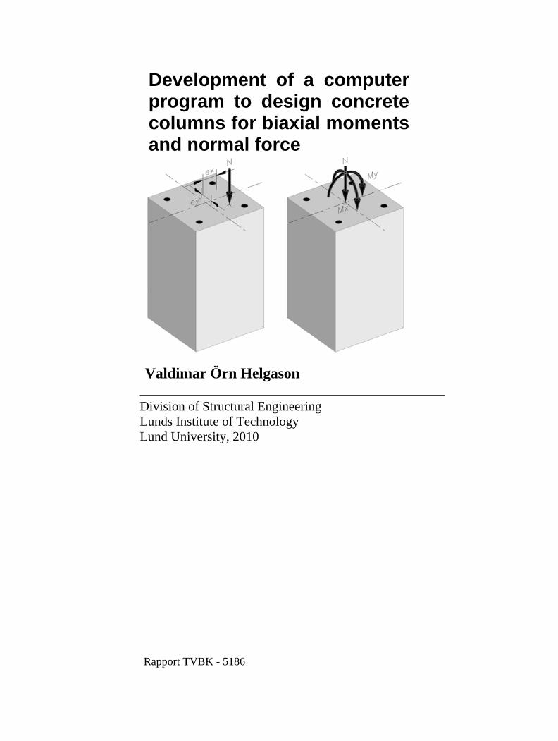
Development of a computer program to design concretecolumns for biaxial momentsand normal force
Valdimar Örn Helgason
Division of Structural Engineering Lunds Institute of Technology Lund University, 2010
Rapport TVBK - 5186

-i-
Avdelningen för Konstruktionsteknik Lunds Tekniska Högskola Box 118 221 00 LUND Department of Structural Engineering Lund Institute of Technology Box 118 S-221 00 LUND Sweden Development of a computer program to design concrete columns for biaxial moments and normal force Utveckling av ett datorprogram för att bestäma kapacitien i betongpelare som belastas av biaxiel böjning och normalkraft Valdimar Örn Helgason 2010 Abstract Design of a concrete column with biaxial moments and normal force is unpractical without the aid of a computer program. It is very time consuming to go through all calculations and to find a suitable layout of a cross-section and positioning of reinforcement for the final design. The goal of this thesis is to create a user friendly computer program for this problem. A critical pier in the Öland Bridge was used as a study case in this thesis. Keywords: Reinforced concrete; Stress/Strain Relationship; Design of Concrete Columns; Uniaxial Moment; Interaction Diagram; Biaxial Moments; Interaction Surface

-ii-
Rapport TVBK-5186 ISSN 0349-4969 ISRN: LUTVDG/TVBK-10/5186+58p Master Thesis Supervisor: Dr. Fredrik Carlsson June 2010

-iii-
Foreword This master thesis was written under the administration of the Division of Structural Engineering at the University of Lund during the period October 2009 – June 2010 under the supervision of Dr. Fredrik Carlsson.
I would like to thank my supervisor Dr. Fredrik Carlsson for all the help and time spent during the work of this thesis. I would also like to thank my friends and colleagues Bzav Abdulkarim, Daniel Honfi, Ívar Björnsson and Jóhannes Helgi Jóhannesson for their support and advice during my time at LTH.
I hope this thesis will help readers to gain further knowledge on the design of reinforced concrete columns for biaxial moments and normal force.
This master thesis is dedicated to my dear grandfather, Valdimar Helgason, and my family for all their love, help and patience during my academic years.
Lund, June 2010 Valdimar Örn Helgason

-iv-
-v-
Table of contents
1 Introduction ........................................................................................................................................... 1
1.1 Background ................................................................................................................................... 1
1.2 Purpose and goal ........................................................................................................................... 1
1.3 Limitations .................................................................................................................................... 1
1.4 Case study ..................................................................................................................................... 2
2 Theory ................................................................................................................................................... 3
2.1 Reinforced concrete ...................................................................................................................... 3
2.2 Stress/strain relationships .............................................................................................................. 3
2.2.1 Concrete ................................................................................................................................ 3
2.2.2 Reinforcement ....................................................................................................................... 4
2.3 Simplified stress/strain diagrams .................................................................................................. 5
2.3.1 Concrete ................................................................................................................................ 5
2.3.2 Reinforcement ....................................................................................................................... 5
2.4 Modes of failure ............................................................................................................................ 6
2.4.1 Ultimate moment capacity less than cracking moment ......................................................... 6
2.4.2 Very small reinforcement ...................................................................................................... 7
2.4.3 Under-reinforced section ....................................................................................................... 7
2.4.4 Balanced design .................................................................................................................... 8
2.4.5 Over-reinforced section ......................................................................................................... 8
2.5 Design possibilities for reinforced sections .................................................................................. 9
2.6 Safety factors for materials ........................................................................................................... 9
2.6.1 Safety classes ........................................................................................................................ 9
2.6.2 Ultimate limit state ................................................................................................................ 9
2.7 Design for axial force .................................................................................................................. 10
2.7.1 Tension ................................................................................................................................ 10
2.7.2 Compression ....................................................................................................................... 10
2.8 Ultimate moment capacity .......................................................................................................... 10
2.8.1 Rectangular solid cross-section ........................................................................................... 12
2.8.2 Rectangular hollow cross-section ....................................................................................... 13
2.9 Design of structural concrete members for axial force and uniaxial moment ............................. 14

-vi-
2.9.1 Interaction diagram ............................................................................................................. 15
2.10 Design of structural concrete members for axial force and biaxial moments ............................. 15
2.10.1 Stress/strain distribution ...................................................................................................... 16
2.10.2 Interaction surface ............................................................................................................... 17
3 Computer program .............................................................................................................................. 19
3.1 Input values ................................................................................................................................. 19
3.1.1 Screen shot .......................................................................................................................... 19
3.1.2 Geometry ............................................................................................................................. 21
3.1.3 Reinforcement ..................................................................................................................... 21
3.1.4 Materials ............................................................................................................................. 22
3.1.4.1 Concrete .......................................................................................................................... 22
3.1.4.2 Reinforcement ................................................................................................................. 22
3.1.5 Number of checks ............................................................................................................... 22
3.1.5.1 Rotation ........................................................................................................................... 22
3.1.5.2 Neutral axis ..................................................................................................................... 22
3.1.6 Loads ................................................................................................................................... 22
3.2 MATLAB functions .................................................................................................................... 22
3.2.1 Input .................................................................................................................................... 23
3.2.2 Transform ............................................................................................................................ 23
3.2.3 Rforce .................................................................................................................................. 23
3.2.4 ConcF .................................................................................................................................. 23
3.2.4.1 Critical rotation ............................................................................................................... 23
3.2.4.2 Cases for different positioning of the neutral axis .......................................................... 24
3.2.4.2.1 Case one .................................................................................................................... 25
3.2.4.2.2 Case two .................................................................................................................... 26
3.2.4.2.3 Case three .................................................................................................................. 26
3.2.4.2.4 Case four ................................................................................................................... 27
3.2.4.2.5 Case five .................................................................................................................... 27
3.2.5 MNCalc ............................................................................................................................... 27
3.3 Example of use with the case study ............................................................................................ 28
3.3.1 Geometry ............................................................................................................................. 28
3.3.2 Reinforcement ..................................................................................................................... 28
3.3.3 Materials ............................................................................................................................. 29

-vii-
3.3.4 Number of checks ............................................................................................................... 29
3.3.5 Load combinations .............................................................................................................. 29
3.3.6 Results ................................................................................................................................. 30
3.3.6.1 Cross-Section .................................................................................................................. 30
3.3.6.2 Interaction surface ........................................................................................................... 30
3.3.6.3 Interaction lines ............................................................................................................... 31
4 Design of structural concrete members for axial force and biaxial moments in Eurocode ................. 33
4.1 Results for design of the case study according to Eurocode ....................................................... 35
5 Conclusion .......................................................................................................................................... 37
6 References ........................................................................................................................................... 39
6.1 Literature ..................................................................................................................................... 39
6.2 Computer programs..................................................................................................................... 39
Annex A. Properties of plane areas ......................................................................................................... 41
φ < φcrit ................................................................................................................................................... 41
φ > φcrit ................................................................................................................................................... 42
Annex B. Detailed calculations for biaxial moments according to Eurocode ......................................... 43
-viii-
Symbols
Theory Ag Gross cross-sectional area of concrete As Area of reinforcement As,Tot Total area of reinforcement ATot Total area b Width of a cross-section ⨍cc Design value for compressive strength of concrete ⨍cck Characteristic compressive cylinder strength of concrete at 28 days (capacity to resist
compressive stress) ⨍ct Design tensile strength of concrete (capacity to resist tensile stress) ⨍d Design value for material strength ⨍k Characteristic value for material strength ⨍st Design value for yield strength of steel ⨍uk Characteristic ultimate strength of steel ⨍yk Characteristic yield strength of steel (capacity to resists stress) d Effective height of reinforcement e Eccentricity (Chapters 2.9 and 2.10) e Height from a chosen point of an area to the center of gravity of the corresponding area (Eq. 2.13) Eck Characteristic modulus of elasticity of concrete Ed Design value for modulus of elasticity Ek Characteristic value for modulus of elasticity Es Design value for modulus of elasticity of steel Esk Characteristic modulus of elasticity of steel Fc Force from concrete Fs Force from reinforcement h Height of a cross-section Mcr Cracking moment equal to moment at which section first cracks Mult Ultimate moment capacity for a specified cross-section N Axial force Nult Ultimate capacity for axial force Nult,C Ultimate compression capacity for a specified cross-section Nult,T Ultimate tension capacity for a specified cross-section x Height of the neutral axis Z Lever arm γn Safety factor, depends on safety class (Chapter 2.6.1) εc0 Compressive strain in the concrete at the peak stress ⨍cc εcu Ultimate compressive strain in the concrete εs Strain in reinforcement εsy The strain in reinforcement when it yields ηγm See chapter 2.6.2 ρ Density of concrete

-ix-
σs Stress in reinforcement
Computer program Ac Area of concrete As Area of reinforcement b Inner height of a cross-section B Outer height of a cross-section ⨍cc Design value for compressive strength of concrete ⨍cck Characteristic compressive cylinder strength of concrete at 28 days (capacity to resist
compressive stress) ⨍st Design value for yield strength of steel ⨍yk Characteristic yield strength of steel (capacity to resists stress) ec Lever arm for concrete force Es Design value for modulus of elasticity of reinforcement Esk Characteristic value for modulus of elasticity of reinforcement l Inner width of a cross-section L Outer width of a cross-section Mx Moment around x-axis My Moment around y-axis N Axial force Ø Diameter of reinforcement t Thickness of hollow cross-section x’ Transformed x coordinate y’ Transformed y coordinate γn Safety factor, depends on safety class (Chapter 2.6.1) εcu Ultimate compressive strain in the concrete εsy The strain in reinforcement when it yields η Heigth of neutral axis for rotated cross-section φ Rotation of cross-section φcrit Critical rotation of cross-section
Design of structural members for axial force and biaxial moments in Eurocode A Area a Exponent for Eq. 4.9 and 4.10 (Table 4.1) ⨍cc Design value for compressive strength of concrete ⨍cck Characteristic compressive cylinder strength of concrete at 28 days (capacity to resist
compressive stress) ⨍st Design value for yield strength of steel ⨍yk Characteristic yield strength of steel (capacity to resists stress) ei Eccentricity along axis i Es Design value for modulus of elasticity of reinforcement Esk Characteristic value for modulus of elasticity of reinforcement Ii Moment of inertia around respective axis i ii Radius of gyration for axis i

-x-
Mdi Design moment around respective axis i MRdi Moment capacity around respective axis i Nd Design axial force NRd Axial force capacity α Coefficient which takes account of the long-term effects of the compressive strength and of the
unfavorable effects resulting from the way in which the load is applied, α = 0,85 if the section is at least as wide at the extreme compressive fibre as it is elsewhere in the compressive zone.
γm Safety factor for material strength
Development of a computer program to design concrete columns for biaxial moments and normal force _____________________________________________________________________________________
_____________________________________________________________________________________
-1-
1 Introduction
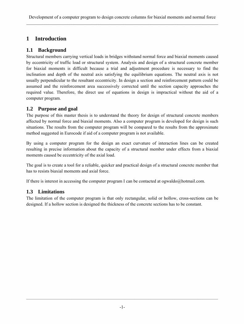
1.1 Background Structural members carrying vertical loads in bridges withstand normal force and biaxial moments caused by eccentricity of traffic load or structural system. Analysis and design of a structural concrete member for biaxial moments is difficult because a trial and adjustment procedure is necessary to find the inclination and depth of the neutral axis satisfying the equilibrium equations. The neutral axis is not usually perpendicular to the resultant eccentricity. In design a section and reinforcement pattern could be assumed and the reinforcement area successively corrected until the section capacity approaches the required value. Therefore, the direct use of equations in design is impractical without the aid of a computer program.
1.2 Purpose and goal The purpose of this master thesis is to understand the theory for design of structural concrete members affected by normal force and biaxial moments. Also a computer program is developed for design is such situations. The results from the computer program will be compared to the results from the approximate method suggested in Eurocode if aid of a computer program is not available.
By using a computer program for the design an exact curvature of interaction lines can be created resulting in precise information about the capacity of a structural member under effects from a biaxial moments caused be eccentricity of the axial load.
The goal is to create a tool for a reliable, quicker and practical design of a structural concrete member that has to resists biaxial moments and axial force.
If there is interest in accessing the computer program I can be contacted at [email protected].
1.3 Limitations The limitation of the computer program is that only rectangular, solid or hollow, cross-sections can be designed. If a hollow section is designed the thickness of the concrete sections has to be constant.

Development of a computer program to design concrete columns for biaxial moments and normal force _____________________________________________________________________________________
_____________________________________________________________________________________
-2-
1.4 Case study The cross-section of a critical column, pier 28, in the Öland Bridge is used as a case study in this master thesis. Due to alkali reactions in the original columns in the Öland Bridge the columns were strengthened by casting a new layer of reinforced concrete around the original cross-section. Only the new cross-section is considered to be the load bearing structure, so the case study is a rectangular hollow cross-section, see fig. 1-1.
Figure 1-1 Cross-section of pier 28 in the Öland Bridge
Development of a computer program to design concrete columns for biaxial moments and normal force _____________________________________________________________________________________
_____________________________________________________________________________________
-3-
2 Theory
2.1 Reinforced concrete Reinforced concrete is perhaps the most widespread structural material presently used around the world. It is a composite material which consists of concrete and steel.
Concrete has many advantages as a structural material but has one great disadvantage of being weak in tension. The concrete cracks under the smallest tensile force, i.e. when the stresses in the structural concrete member are greater than the tension strength ⨍ct.
Steel has high tensile strength and is placed as reinforcement at tensile zones in the structural concrete member, i.e. once the concrete cracks the tensile force is carried by the reinforcement crossing the cracks. Therefore the advantages of both materials are utilized when the concrete area resists compressive stresses while the reinforcement bars resists tensile stresses.
2.2 Stress/strain relationships
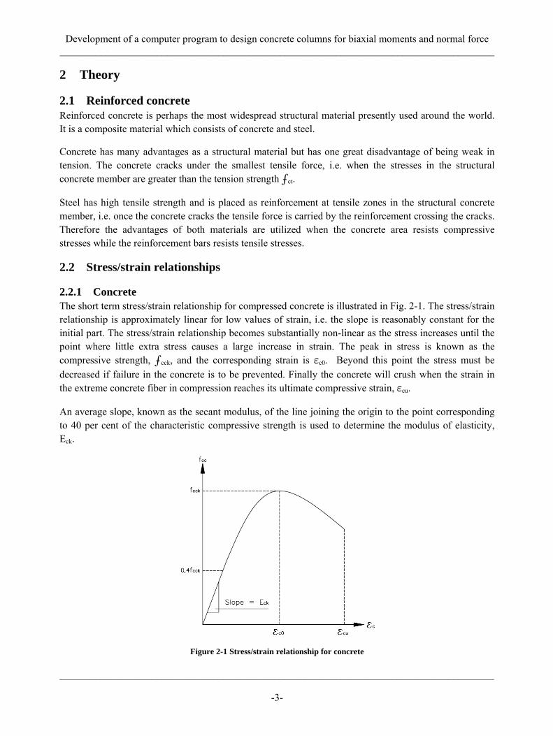
2.2.1 Concrete The short term stress/strain relationship for compressed concrete is illustrated in Fig. 2-1. The stress/strain relationship is approximately linear for low values of strain, i.e. the slope is reasonably constant for the initial part. The stress/strain relationship becomes substantially non-linear as the stress increases until the point where little extra stress causes a large increase in strain. The peak in stress is known as the compressive strength, ⨍cck, and the corresponding strain is εc0. Beyond this point the stress must be decreased if failure in the concrete is to be prevented. Finally the concrete will crush when the strain in the extreme concrete fiber in compression reaches its ultimate compressive strain, εcu.
An average slope, known as the secant modulus, of the line joining the origin to the point corresponding to 40 per cent of the characteristic compressive strength is used to determine the modulus of elasticity, Eck.
Figure 2-1 Stress/strain relationship for concrete

Development of a computer program to design concrete columns for biaxial moments and normal force _____________________________________________________________________________________
_____________________________________________________________________________________
-4-
2.2.2 Reinforcement The stress/strain relationship for steel, in compression or tension, begins with a straight line from the origin to the proportional limit. That region is called the linear/elastic region. Beyond that point the strain begins to increase more rapidly for each increment in stress, the stress/strain curve has a smaller and smaller slope, until the steel yields (the yield point). Beyond the yield point considerable elongation of the steel occurs with no noticeable increase in the tensile force, known as the yielding phenomenon or perfectly plastic region. The corresponding stress for the yield point is known as the yield stress, ⨍yk, of the steel. The yield strength of the reinforcement is though defined as the stress at which the strain has exceeded the value predicted by the linear relationship by 0,002, known as the offset method. After the steel has undergone large strains that occur during yielding the steel begins to strain harden, that results in increased resistance of the steel to further deformation. At last the load reaches its maximum value and the corresponding stress is called the ultimate stress, ⨍uk. A typical stress/strain diagram for reinforcement in tension or compression is illustrated in Fig. 2-2.
The slope of the linear/elastic region is used to determine the modulus of elasticity for the steel, Esk.
Figure 2-2 Stress/strain relationship for reinforcement

Development of a computer program to design concrete columns for biaxial moments and normal force _____________________________________________________________________________________
_____________________________________________________________________________________
-5-
2.3 Simplified stress/strain diagrams Instead of using the actual stress/strain diagrams that have been explained simplified stress/strain diagrams are used for design in this thesis.
2.3.1 Concrete A parabolic-rectangular diagram is used for the concrete, Fig. 2-3.
Figure 2-3 Simplified stress/strain diagram for concrete
2.3.2 Reinforcement A horizontal top branch diagram is used for the reinforcement, Fig. 2-4. In that case no limit on the steel strain is necessary.
Figure 2-4 Simplified stress/strain diagram for steel
Development of a computer program to design concrete columns for biaxial moments and normal force _____________________________________________________________________________________
_____________________________________________________________________________________
-6-
2.4 Modes of failure There are five modes of failure for reinforced concrete sections which all depend on the amount of reinforcement placed in the section.
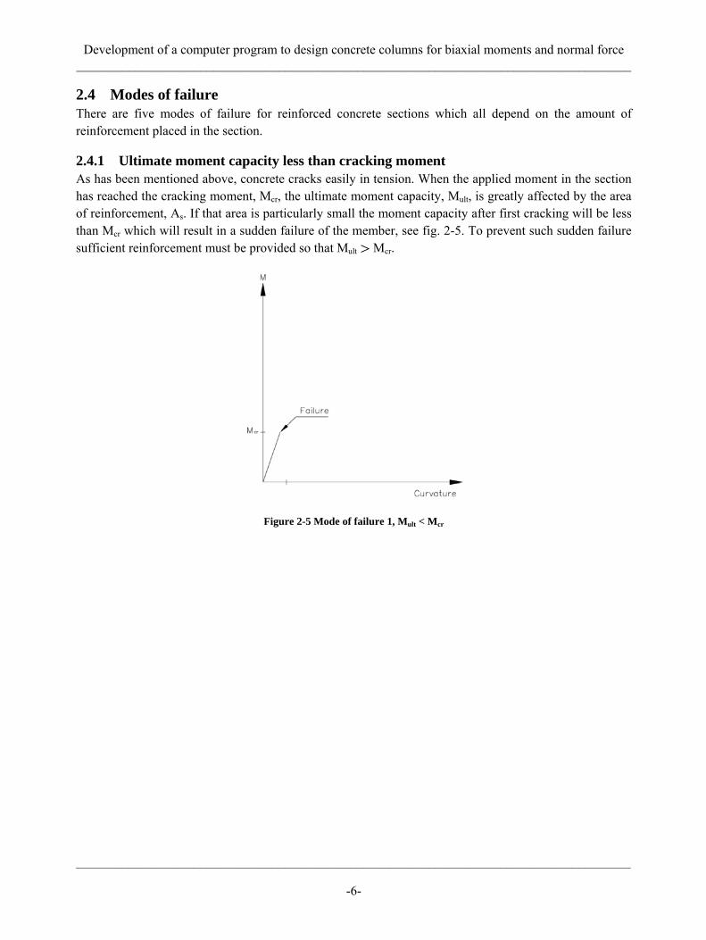
2.4.1 Ultimate moment capacity less than cracking moment As has been mentioned above, concrete cracks easily in tension. When the applied moment in the section has reached the cracking moment, Mcr, the ultimate moment capacity, Mult, is greatly affected by the area of reinforcement, As. If that area is particularly small the moment capacity after first cracking will be less than Mcr which will result in a sudden failure of the member, see fig. 2-5. To prevent such sudden failure sufficient reinforcement must be provided so that Mult > Mcr.
Figure 2-5 Mode of failure 1, Mult < Mcr

Development of a computer program to design concrete columns for biaxial moments and normal force _____________________________________________________________________________________
_____________________________________________________________________________________
-7-
2.4.2 Very small reinforcement When the moment capacity is increased with more reinforcement, so it will be greater than the cracking moment, but the area of reinforcement is still considered small, failure mode 2 occurs. The reinforcement yields before the maximum compressive strain in the concrete reaches the maximum compressive strain, εcu, and plastic deformations will occur, see fig. 2-6. That results in considerable deformations before the reinforcement will fail completely.
Figure 2-6 Mode of failure 2, very small reinforcement
2.4.3 Under-reinforced section Larger area of reinforcement is used in the section where the reinforcement yields but the strain in the concrete reaches its maximum before the reinforcement fails. Thus, the failure of the section is due to crushing of the concrete in compression, see fig. 2-7. Because the amount of reinforcement is still considered small the section is termed under-reinforced.
Figure 2-7 Mode of failure 3, under-reinforced
Development of a computer program to design concrete columns for biaxial moments and normal force _____________________________________________________________________________________
_____________________________________________________________________________________
-8-
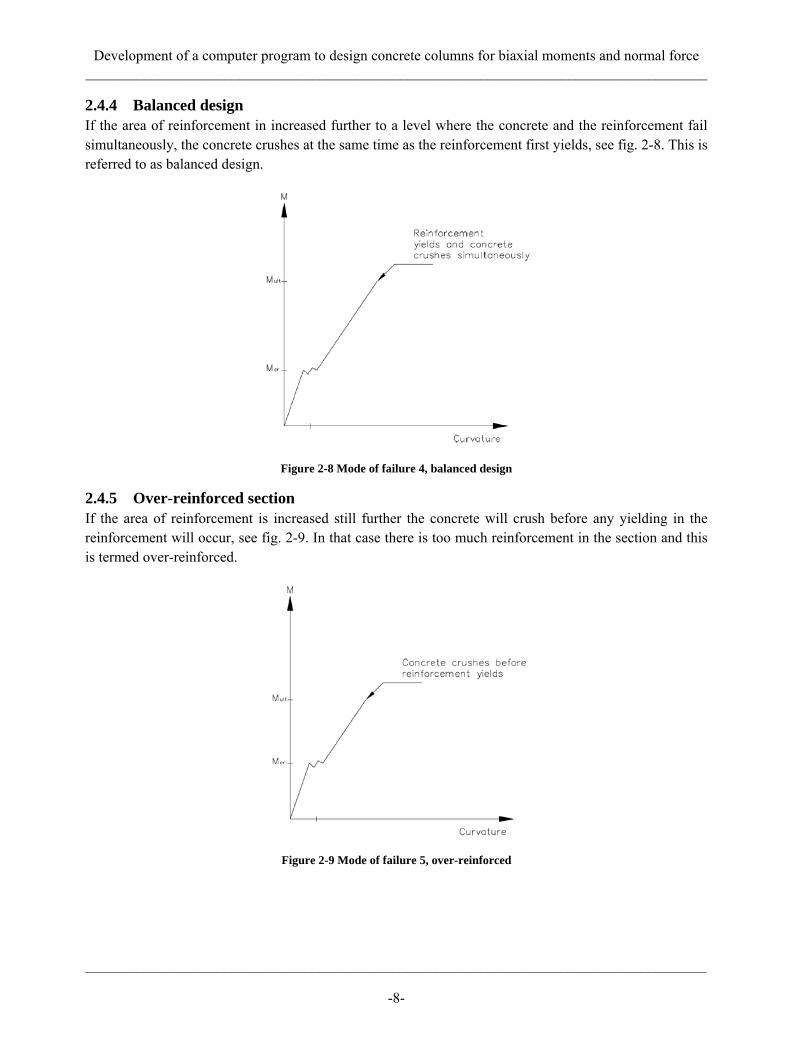
2.4.4 Balanced design If the area of reinforcement in increased further to a level where the concrete and the reinforcement fail simultaneously, the concrete crushes at the same time as the reinforcement first yields, see fig. 2-8. This is referred to as balanced design.
Figure 2-8 Mode of failure 4, balanced design
2.4.5 Over-reinforced section If the area of reinforcement is increased still further the concrete will crush before any yielding in the reinforcement will occur, see fig. 2-9. In that case there is too much reinforcement in the section and this is termed over-reinforced.
Figure 2-9 Mode of failure 5, over-reinforced
Development of a computer program to design concrete columns for biaxial moments and normal force _____________________________________________________________________________________
_____________________________________________________________________________________
-9-
2.5 Design possibilities for reinforced sections The fourth and fifth modes of failure act as failure of a brittle material, i.e. there is no plastic deformation of the reinforcement prior to collapse. Since there will be no warning of failure and it will happen suddenly these modes are unacceptable forms of failure in design situations. To prevent a brittle failure design codes specify maximum allowable values for the area of reinforcement.
Large plastic deformation will occur prior to failure for modes two and three, there is a ample warning of imminent failure. Those modes are referred to as ductile failures and are highly desirable in design of reinforced concrete structures.
2.6 Safety factors for materials Material strengths are stochastic variables and estimates of their characteristic values must be made for design.
Characteristic strengths are values below which a minimum number (usually 5 per cent) of specimens are expected to fail. To allow for the possibility that the material resistance is less than its characteristic value BBK 04 states safety factors to estimate the design values for three different safety classes. The safety classes are determined by the following consequences of structural failure and are taken into account in the design value by the parameter γn, which is different for the different safety classes.
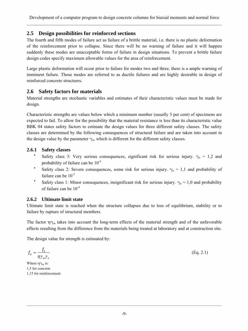
2.6.1 Safety classes • Safety class 3: Very serious consequences, significant risk for serious injury. γn = 1,2 and
probability of failure can be 10-6
• Safety class 2: Severe consequences, some risk for serious injury. γn = 1,1 and probability of failure can be 10-5
• Safety class 1: Minor consequences, insignificant risk for serious injury. γn = 1,0 and probability of failure can be 10-4
2.6.2 Ultimate limit state Ultimate limit state is reached when the structure collapses due to loss of equilibrium, stability or to failure by rupture of structural members.
The factor ηγm takes into account the long-term effects of the material strength and of the unfavorable effects resulting from the difference from the materials being treated at laboratory and at construction site.
The design value for strength is estimated by:
kd
m n
ffηγ γ
= (Eq. 2.1)
Where ηγm is: 1,5 for concrete 1,15 for reinforcement
Development of a computer program to design concrete columns for biaxial moments and normal force _____________________________________________________________________________________
_____________________________________________________________________________________
-10-
The design value for stiffness is estimated by:
kd
m n
EEηγ γ
= (Eq. 2.2)
Where ηγm is: 1,2 for concrete 1,05 for reinforcement
2.7 Design for axial force Axial force can both act on the structural member as tension or compression.
2.7.1 Tension As has been mentioned above concrete cracks under the smallest tensile force and therefore only the reinforcement in tension is used for the design for tensile forces. The tensile strength of a structural member of reinforced concrete is:
, ,ult T st s TotN f A= (Eq. 2.3) Where: ⨍st = Design value for tensile strength of the reinforcement As,Tot = Total area of all the the reinforcement
2.7.2 Compression Concrete has high compression strength and the reinforcement has the same strength in compression as in tension. Therefore both materials can be used to determine the capacity for compression. The compression strength of a structural member of reinforced concrete is:
( ), , ,ult C cc g s Tot st s TotN f A A f A= − + (Eq. 2.4)
Where: ⨍cc = Design value for compressive strength of the concrete Ag = Gross cross-sectional area of the concrete As,Tot = Total area of all the the reinforcement ⨍st = Design value for tensile strength of the reinforcement
2.8 Ultimate moment capacity The ultimate moment capacity, Mult, can be calculated for a structural member of reinforced concrete with specified dimensions and areas of reinforcement with combination of the simplified design stress/strain diagrams for concrete and steel. The ultimate compressive strain in the concrete is stated in BBK 04 as:
0, 4 0,6 0,00352200cuρε ⎛ ⎞= +⎜ ⎟
⎝ ⎠ (Eq. 2.5)
With ρ = 2200 kg/m3 for normal or heavy concrete which yields εcu = 0,0035
Equilibrium of forces from the concrete and the reinforcement can be used to determine the ultimate moment capacity of a section in bending. Moment is taken around the center of gravity for the cross-section with forces from the compressed area of the concrete and compressed/tensile area of the reinforcement. BBK 04 states that 80 percent of the compressed concrete area can be used. The lever arm

Development of a computer program to design concrete columns for biaxial moments and normal force _____________________________________________________________________________________
_____________________________________________________________________________________
-11-
of the concrete force is taken from the center of gravity of the compressed concrete zone to the center of gravity of the whole section. The appropriated signs for forces in equations for moment capacity are negative for tension and positive for compression.
The concrete force is:
0,8c ccF xbf= (Eq. 2.6) Where: x = Height of the neutral axis, see fig. 2-10 and 2-12 b = Width of the cross-section ⨍cc = Design value for compressive strength of the concrete
The force from the reinforcement is determined by the strain in the steel with:
s cux d
xε ε −
= (Eq. 2.7)
Where: εcu = 0 0035 d = Effective height of the reinforcement, see fig. 2-10 and 2-12
If the steel has yielded the strain will be set equal to the strain where the steel yields which is:
stsy
s
fE
ε = (Eq. 2.8)
Where: ⨍st = Design value for the yield strength of the reinforcement Es = Design value for the modulus of elasticity for the reinforcement
The stress in the reinforcement will then be:
• When the reinforcement has yielded: s sy s stfε ε σ≥ ⇒ = (Eq. 2.9)
• When the reinforcement has not yielded: s sy s s sEε ε σ ε< ⇒ = (Eq. 2.10)
The force from each rebar will then be:
s s sF Aσ= (Eq. 2.11) Where: As = The area of the reinforcement σs = The stress in the reinforcement
Development of a computer program to design concrete columns for biaxial moments and normal force _____________________________________________________________________________________
_____________________________________________________________________________________
-12-
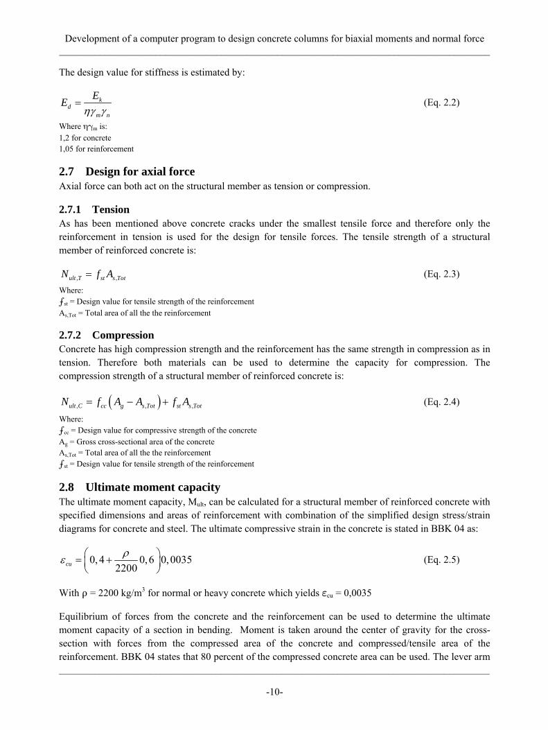
2.8.1 Rectangular solid cross-section
Figure 2-10 Explanation for symbols and strain/stress distribution for a structural concrete member with a rectangular
solid cross-section
The equilibrium for the ultimate moment capacity of the beam in fig. 2-10 will then be, see fig. 2-11:
Figure 2-11 Equilibrium for the ultimate moment capacity for a rectangular solid cross-section
( )0,42ult c shM F x F x d⎛ ⎞= − + −⎜ ⎟
⎝ ⎠ (Eq. 2.12)
The reinforcement is in tension so the sign of the force will be negative as well as the lever arm since the effective height of the bar is greater than the neutral axis resulting in a positive corresponding moment from the reinforcement. The lever arm for the axial force is zero, i.e. the axial force will not affect the results as long as the moment is taken around the center of gravity for the cross-section.
Development of a computer program to design concrete columns for biaxial moments and normal force _____________________________________________________________________________________
_____________________________________________________________________________________
-13-
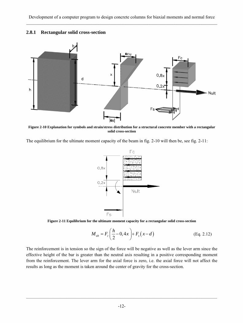
2.8.2 Rectangular hollow cross-section
Figure 2-12 Explanation for symbols and strain/stress distribution for a structural concrete member with a rectangular hollow cross-section
Since the center of gravity for the concrete force is not placed at the center of the compressed concrete the first step for rectangular hollow cross-section is to determine the lever arm using the following procedure.
The lever arm, Z, from the neutral axis is determined by dividing the compressed concrete area to a system of sub-areas. The height from the bottom of the compressed area to the center of gravity for the corresponding area, e, is determined with:
i i
Tot
Aee
A= ∑
(Eq. 2.13)
Where: Ai = The area of sub-area i ei = The distance from the bottom of the whole area to the center of gravity of sub-area i, Fig. 2-13. ATot = Total area of all sub-areas
Figure 2-13 Explanation of sub-areas and the corresponding distance from a chosen point to their center of gravity
The lever arm will then be: Z = 0,2x+e (Eq. 2.14)
Development of a computer program to design concrete columns for biaxial moments and normal force _____________________________________________________________________________________
_____________________________________________________________________________________
-14-
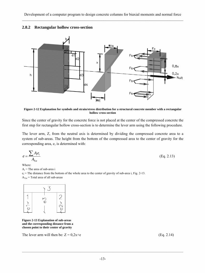
The equilibrium for the ultimate moment capacity of the beam in fig. 2-12 will then be, see fig. 2-14:
Figure 2-14 Equilibrium for the ultimate moment capacity for a rectangular solid cross-section, the force from the concrete is shown as a arrow placed at the center of gravity for the compressed concrete area
( )ult c sM F Z F x d= ⋅ + −∑ (Eq. 2.15)
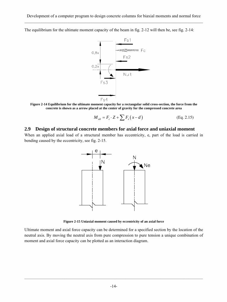
2.9 Design of structural concrete members for axial force and uniaxial moment When an applied axial load of a structural member has eccentricity, e, part of the load is carried in bending caused by the eccentricity, see fig. 2-15.
Figure 2-15 Uniaxial moment caused by eccentricity of an axial force
Ultimate moment and axial force capacity can be determined for a specified section by the location of the neutral axis. By moving the neutral axis from pure compression to pure tension a unique combination of moment and axial force capacity can be plotted as an interaction diagram.

Development of a computer program to design concrete columns for biaxial moments and normal force _____________________________________________________________________________________
_____________________________________________________________________________________
-15-
2.9.1 Interaction diagram Interaction diagram is a graph illustrating the capacity of a structural concrete member to resist a range of combinations of moment and axial force. By changing the location of the neutral axis, giving different size of compressive and tension zones, each case will lead to a different capacity calculated from the strain distribution. First the section is in pure compressions, then it will be over-reinforced until it reaches the point where it is balanced designed. After the point of balanced design the section will reach pure bending, then be under-reinforced and finally be in pure tension, see fig. 2-16.
Figure 2-16 Interaction diagram
2.10 Design of structural concrete members for axial force and biaxial moments If a structural member is simultaneously subjected to bending about two, usually perpendicular, axes it is referred to as biaxial moments. Like uniaxial moment biaxial moments is caused by eccentric loading of the structural member, see fig. 2-17.
Figure 2-17 Biaxial moments caused by eccentricity of axial force
Development of a computer program to design concrete columns for biaxial moments and normal force _____________________________________________________________________________________
_____________________________________________________________________________________
-16-
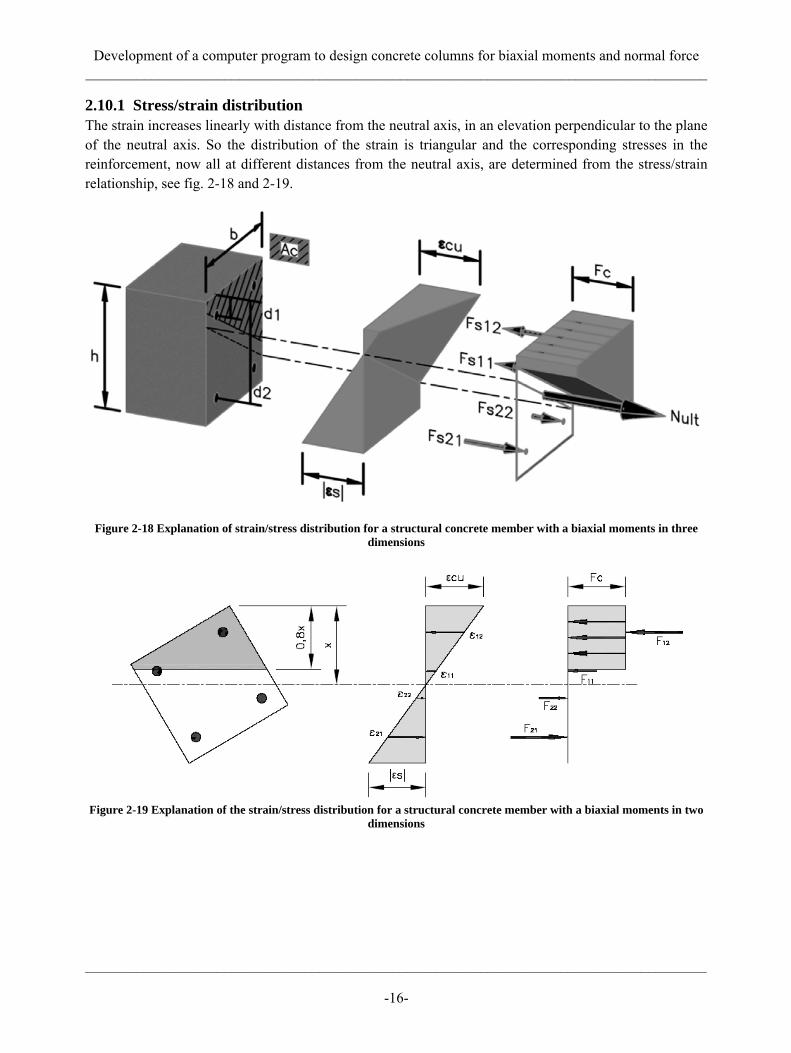
2.10.1 Stress/strain distribution The strain increases linearly with distance from the neutral axis, in an elevation perpendicular to the plane of the neutral axis. So the distribution of the strain is triangular and the corresponding stresses in the reinforcement, now all at different distances from the neutral axis, are determined from the stress/strain relationship, see fig. 2-18 and 2-19.
Figure 2-18 Explanation of strain/stress distribution for a structural concrete member with a biaxial moments in three dimensions
Figure 2-19 Explanation of the strain/stress distribution for a structural concrete member with a biaxial moments in two
dimensions

Development of a computer program to design concrete columns for biaxial moments and normal force _____________________________________________________________________________________
_____________________________________________________________________________________
-17-
The shape of the compression zone of the concrete depends on the inclination of the neutral axis, see fig. 2-20.
Figure 2-20 Four different shapes of the concrete zone for a rectangular cross-section
2.10.2 Interaction surface For structural concrete members affected by biaxial moments the same principles are used as for a structural member affected by uniaxial moment, by varying the inclination of the neutral axis and creating an interaction diagram. By creating interaction diagrams at various angles a series of diagrams is created to form the interaction surface, see fig. 2-21. Each point on this surface represents one particular set of axial load and bending about the major axes, x and y, see fig. 2-21.
Figure 2-21 Example of interaction surface

Development of a computer program to design concrete columns for biaxial moments and normal force _____________________________________________________________________________________
_____________________________________________________________________________________
-18-
If a horizontal section is taken through the interaction surface, for given axial load, an interaction line is created which shows the possible combination of moments about the major axes, see fig. 2-22. The shape of the interaction line varies with the section geometry and the level of the axial load.
Figure 2-22 Series of interaction lines for different axial forces
Development of a computer program to design concrete columns for biaxial moments and normal force _____________________________________________________________________________________
_____________________________________________________________________________________
-19-
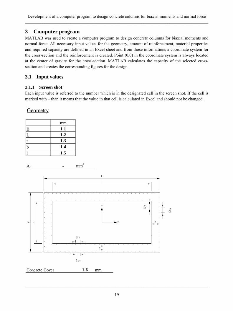
3 Computer program MATLAB was used to create a computer program to design concrete columns for biaxial moments and normal force. All necessary input values for the geometry, amount of reinforcement, material properties and required capacity are defined in an Excel sheet and from those informations a coordinate system for the cross-section and the reinforcement is created. Point (0,0) in the coordinate system is always located at the center of gravity for the cross-section. MATLAB calculates the capacity of the selected cross-section and creates the corresponding figures for the design.
3.1 Input values
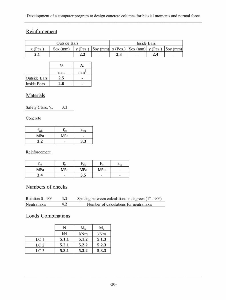
3.1.1 Screen shot Each input value is referred to the number which is in the designated cell in the screen shot. If the cell is marked with – than it means that the value in that cell is calculated in Excel and should not be changed.
Geometry
mmB 1.1L 1.2t 1.3b 1.4l 1.5
Ac - mm2
Concrete Cover 1.6 mm
Development of a computer program to design concrete columns for biaxial moments and normal force _____________________________________________________________________________________
_____________________________________________________________________________________
-20-
Reinforcement
x (Pcs.) Sox (mm) y (Pcs.) Soy (mm) x (Pcs.) Sox (mm) y (Pcs.) Soy (mm)2.1 - 2.2 - 2.3 - 2.4 -
Outside Bars Inside Bars
∅ As
mm mm2
Outside Bars 2.5 -Inside Bars 2.6 -
Materials
Safety Class, γn 3.1
Concrete
fcck fcc εcu
MPa MPa -3.2 - 3.3
Reinforcement
fyk fst Esk Es εsy
MPa MPa MPa MPa -3.4 - 3.5 - -
Numbers of checks
Rotation 0 - 90° 4.1Neutral axis 4.2
Spacing between calculations in degrees (1° - 90°)Number of calculations for neutral axis
Loads Combinations
N Mx My
kN kNm kNmLC 1 5.1.1 5.1.2 5.1.3LC 2 5.2.1 5.2.2 5.2.3LC 3 5.3.1 5.3.2 5.3.3
Development of a computer program to design concrete columns for biaxial moments and normal force _____________________________________________________________________________________
_____________________________________________________________________________________
-21-
3.1.2 Geometry As stated in the introduction only rectangular cross-sections can be designed with the computer program. Six values are needed to create the cross-section, explained below.
B: The outer height of the cross-section, cell 1.1
L: The outer width of the cross-section, cell 1.2
t: Thickness of the concrete section. Only used for calculation of a hollow section and must be the same for the whole section, put as 0 for a solid section, cell 1.3
b: The inner height of the cross-section. Only used for calculation of a hollow section, put as 0 for a solid section, cell 1.4
l: The inner width of the cross-section. Only used for calculation of a hollow section, put as 0 for a solid section, cell 1.5
Concrete cover: The distance from the outer surface of the cross-section to the outer limit of the reinforcement, cell 1.6
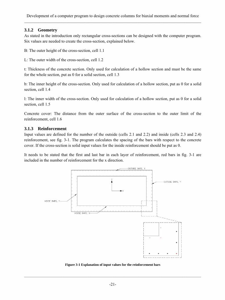
3.1.3 Reinforcement Input values are defined for the number of the outside (cells 2.1 and 2.2) and inside (cells 2.3 and 2.4) reinforcement, see fig. 3-1. The program calculates the spacing of the bars with respect to the concrete cover. If the cross-section is solid input values for the inside reinforcement should be put as 0.
It needs to be stated that the first and last bar in each layer of reinforcement, red bars in fig. 3-1 are included in the number of reinforcement for the x direction.
Figure 3-1 Explanation of input values for the reinforcement bars
Development of a computer program to design concrete columns for biaxial moments and normal force _____________________________________________________________________________________
_____________________________________________________________________________________
-22-
The diameter of the reinforcement is then defined, both outside (cell 2.5) and inside (cell 2.6). If there is no inside reinforcement that should already have been defined as zero amount of bars so it does not matter if the value of the diameter of inside bars is not zero.
3.1.4 Materials The first input value for the materials is the factor γn (cell 3.1) which depends on the safety class for the design, see the chapter 2.6 (Safety factor for materials).
3.1.4.1 Concrete The input values for the concrete are:
The characteristic compressive strength, ⨍cck, cell 3.2
and
The ultimate compressive strain, εcu, cell 3.3
3.1.4.2 Reinforcement The input values for the reinforcement are:
The characteristic yield strength, ⨍yk, cell 3.4
and
The characteristic modulus of elasticity, Esk, cell 3.5
3.1.5 Number of checks Used to define the accuracy of the calculations. Less spacing between rotation of the cross-section and the neutral axis leads to more accuracy of the result.
3.1.5.1 Rotation The rotation of the cross-section is defined (cell 4.1) as spacing between calculations from 0° to 90°, i.e. if the value is chosen as 30° calculations will be made for 0°, 30°, 60° and 90°.
3.1.5.2 Neutral axis Number of calculated neutral axes is defined here (cell 4.2), pure compression and pure tension is always included in the calculations.
3.1.6 Loads Used to define the combinations of axial force and bending about the major axes, x and y, that should be checked for the design (cells 5.1.1 to 5.3.3). These combinations are plotted on interaction lines for the defined axial force, i.e. showing if the capacity of the section fulfills the requirements.
3.2 MATLAB functions Five MATLAB functions were created for the calculations of the capacity of the cross-section. Each function will be explained on the next pages.
Development of a computer program to design concrete columns for biaxial moments and normal force _____________________________________________________________________________________
_____________________________________________________________________________________
-23-
3.2.1 Input Function file used to collect all input values and the coordinate system for the cross-section and all reinforcement.
3.2.2 Transform Function file used to transform global node position vectors (x,y) to local position vectors (x’,y’) for a given rotation (φ) of the coordinate axis. The corresponding formulas are used:
' cos sinx x yϕ ϕ= − (Eq. 3.1)
' sin cosy x yϕ ϕ= + (Eq. 3.2)
3.2.3 Rforce Function used to calculate the force vector for a given position matrix and corresponding area vector which represents the location and area properties of the reinforcement bars. Input includes position matrix of the concrete cross-section, reinforcement bars and depth of the neutral axis. The strain and the corresponding stress in the reinforcement is calculated and then the force from each bar.
3.2.4 ConcF Function used to find the compressed area of concrete and corresponding center of gravity for a given number of neutral axes which are to be checked.
Further explanations will be described below in similar steps as the function works.
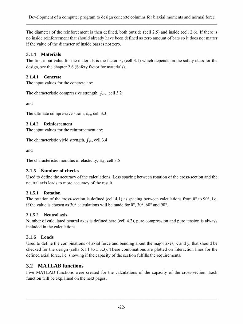
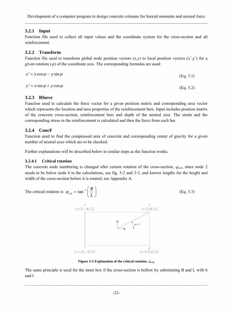
3.2.4.1 Critical rotation The concrete node numbering is changed after certain rotation of the cross-section, φcrit, since node 2 needs to be below node 4 in the calculations, see fig. 3-2 and 3-3, and known lengths for the height and width of the cross-section before it is rotated, see Appendix A.
The critical rotation is: 1tancritBL
ϕ − ⎛ ⎞= ⎜ ⎟⎝ ⎠
(Eq. 3.3)
Figure 3-2 Explanation of the critical rotation, φcrit
The same principle is used for the inner box if the cross-section is hollow by substituting B and L with b and l.
Development of a computer program to design concrete columns for biaxial moments and normal force _____________________________________________________________________________________
_____________________________________________________________________________________
-24-
Figure 3-3 Example of how nodes 2 and 4 changes for rotation below and above critical rotation
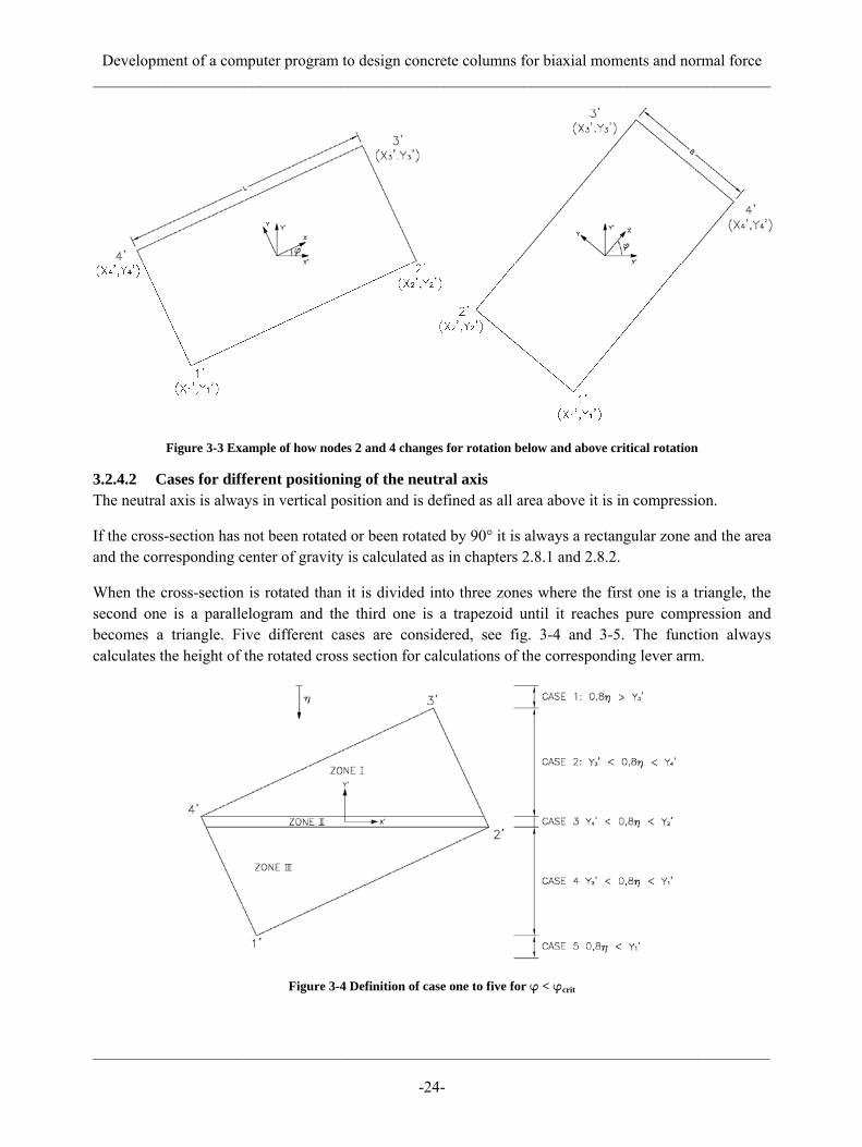
3.2.4.2 Cases for different positioning of the neutral axis The neutral axis is always in vertical position and is defined as all area above it is in compression.
If the cross-section has not been rotated or been rotated by 90° it is always a rectangular zone and the area and the corresponding center of gravity is calculated as in chapters 2.8.1 and 2.8.2.
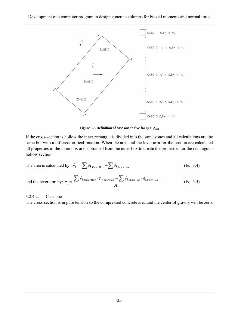
When the cross-section is rotated than it is divided into three zones where the first one is a triangle, the second one is a parallelogram and the third one is a trapezoid until it reaches pure compression and becomes a triangle. Five different cases are considered, see fig. 3-4 and 3-5. The function always calculates the height of the rotated cross section for calculations of the corresponding lever arm.
Figure 3-4 Definition of case one to five for φ < φcrit
Development of a computer program to design concrete columns for biaxial moments and normal force _____________________________________________________________________________________
_____________________________________________________________________________________
-25-
Figure 3-5 Definition of case one to five for φ > φcrit
If the cross-section is hollow the inner rectangle is divided into the same zones and all calculations are the same but with a different critical rotation. When the area and the lever arm for the section are calculated all properties of the inner box are subtracted from the outer box to create the properties for the rectangular hollow section.
The area is calculated by: ,Outer Box ,Inner Boxc i iA A A= −∑ ∑ (Eq. 3.4)
and the lever arm by: ,Outer Box ,Outer Box ,Inner Box ,Inner Boxi i i ic
c
A e A ee
A⋅ − ⋅
= ∑ ∑ (Eq. 3.5)
3.2.4.2.1 Case one The cross-section is in pure tension so the compressed concrete area and the center of gravity will be zero.
Development of a computer program to design concrete columns for biaxial moments and normal force _____________________________________________________________________________________
_____________________________________________________________________________________
-26-
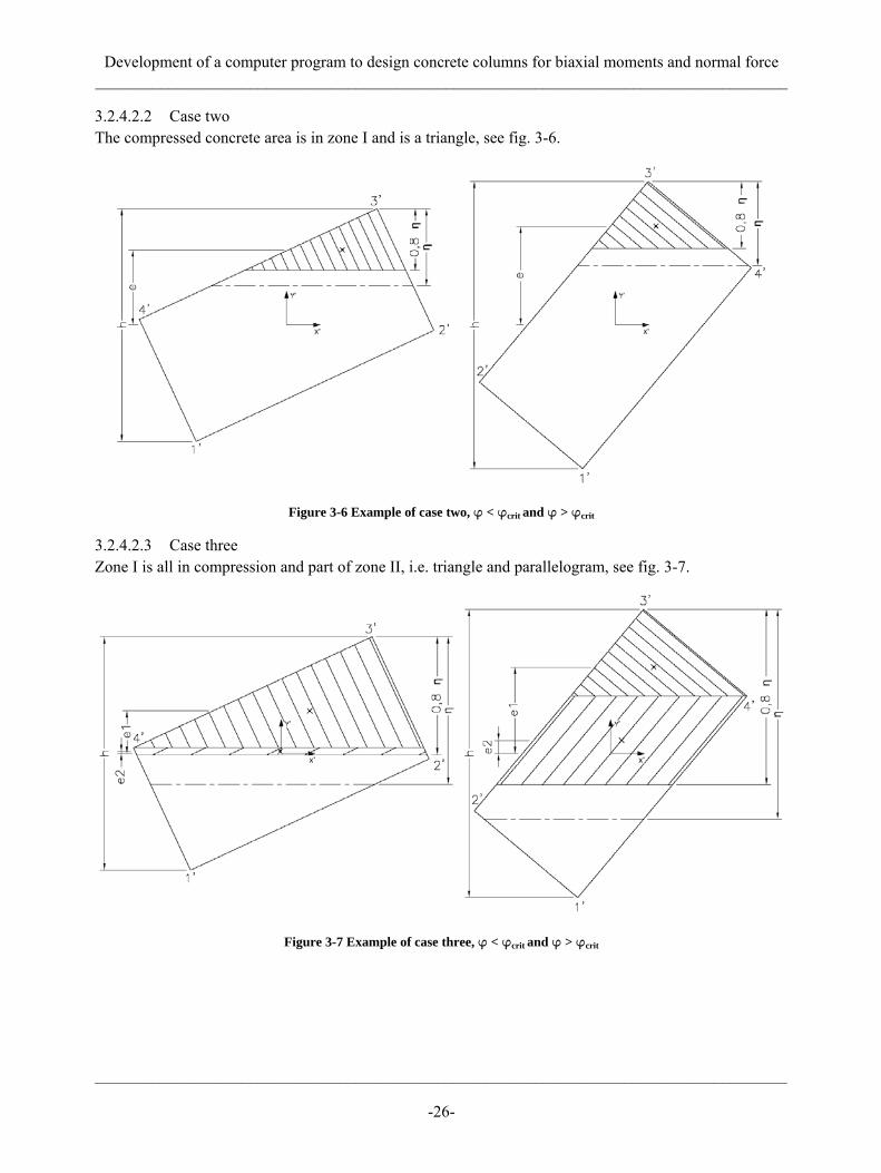
3.2.4.2.2 Case two The compressed concrete area is in zone I and is a triangle, see fig. 3-6.
Figure 3-6 Example of case two, φ < φcrit and φ > φcrit
3.2.4.2.3 Case three Zone I is all in compression and part of zone II, i.e. triangle and parallelogram, see fig. 3-7.
Figure 3-7 Example of case three, φ < φcrit and φ > φcrit

Development of a computer program to design concrete columns for biaxial moments and normal force _____________________________________________________________________________________
_____________________________________________________________________________________
-27-
3.2.4.2.4 Case four Zone I and II are both in compression and part of zone III, i.e. triangle, parallelogram and trapezoid, see fig. 3-8.
Figure 3-8 Example of case four, φ < φcrit and φ > φcrit
3.2.4.2.5 Case five The cross-section is in pure compression so the compressed concrete area will be zone I, II and III. The center of gravity will be at the same point as the moment is taken around so the moment capacity will be zero.
3.2.5 MNCalc This function returns the results for the design. It sums up the forces from the reinforcement and the concrete for all neutral axes and rotations that have been chosen to be checked. Then it calculates the capacity of the section for axial force and bending. Finally it plots figures of the cross-section, the interaction surface (with and without contour lines), interaction lines for chosen load combinations and development if the interaction lines by showing different lines for decreasing axial force capacity.

Development of a computer program to design concrete columns for biaxial moments and normal force _____________________________________________________________________________________
_____________________________________________________________________________________
-28-
3.3 Example of use with the case study As was mentioned the case study is a rectangular hollow cross-section, see fig. 3-9. Input values are marked as bold.
Figure 3-9 Cross-section of the case study
3.3.1 Geometry Input values for the geometry of the cross-section are:
3.3.2 Reinforcement Input values for the reinforcement are:
mmB 4000L 7800t 580b 2840l 6640
Concrete Cover 50 mm
x (Pcs.) Sox (mm) y (Pcs.) Soy (mm) x (Pcs.) Sox (mm) y (Pcs.) Soy (mm)30 264,7 11 322,9 22 321,5 9 295,2
Outside Bars Inside Bars
∅ Amm mm2
Outside Bars 25 490,87Inside Bars 12 113,10

Development of a computer program to design concrete columns for biaxial moments and normal force _____________________________________________________________________________________
_____________________________________________________________________________________
-29-
3.3.3 Materials The input values for the materials are:
3.3.4 Number of checks The input values for the numbers of checks are:
3.3.5 Load combinations The load combinations are:
Safety Class, γn 1,2
Concrete
fcck fcc εcu
MPa MPa -28,5 15,83 0,0035
Reinforcement
fyk fst Esk Es εsy
MPa MPa MPa MPa -390 282,61 200.000 158.730 0,00178
Rotation 0 - 90° 1Neutral axis 100
Spacing between calculations in degrees (1° - 90°)Number of calculations for neutral axis
N Mx My
kN kNm kNmLC 1 41.012 109.556 30.443LC 2 40.730 102.452 29.539LC 3 39.450 47.127 74.349
Development of a computer program to design concrete columns for biaxial moments and normal force _____________________________________________________________________________________
_____________________________________________________________________________________
-30-
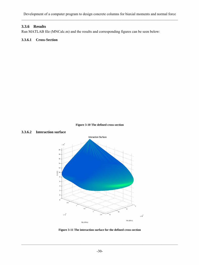
3.3.6 Results Run MATLAB file (MNCalc.m) and the results and corresponding figures can be seen below:
3.3.6.1 Cross-Section
Figure 3-10 The defined cross-section
3.3.6.2 Interaction surface
Figure 3-11 The interaction surface for the defined cross-section

Development of a computer program to design concrete columns for biaxial moments and normal force _____________________________________________________________________________________
_____________________________________________________________________________________
-31-
3.3.6.3 Interaction lines
Figure 3-12 Load combination 1, marked with a star, which is just outside the surface of safe design, i.e. the capacity of the cross-section does not fulfill the requirements.
Figure 3-13 Load combination 2, marked with a star, which is inside the surface of safe design, i.e. the capacity of the cross-section fulfills the requirements.

Development of a computer program to design concrete columns for biaxial moments and normal force _____________________________________________________________________________________
_____________________________________________________________________________________
-32-
Figure 3-14 Load combination 3, marked with a star, which is inside the surface of safe design, i.e. the capacity of the cross-section fulfills the requirements.
Figure 3-15 Development of the interaction lines for the defined cross-section

Development of a computer program to design concrete columns for biaxial moments and normal force _____________________________________________________________________________________
_____________________________________________________________________________________
-33-
4 Design of structural concrete members for axial force and biaxial moments in Eurocode
Chapter 5.8.9 in EN 1992-1-1-2004 includes a simplified design of structural concrete members in biaxial moments if a computer program is not used for the design.
First it should be stated that the safety factors for materials are not the same in Eurocode and BBK 04. The strength of the materials according to Eurocode is:
Concrete:
cckcc
m
ff αγ
= (Eq. 4.1)
Where: α = coefficient which takes account of the long-term effects of the compressive strength and of the unfavorable effects resulting from the way in which the load is applied, α = 0,85 if the section is at least as wide at the extreme compressive fibre as it is elsewhere in the compressive zone. γm = 1,5
Reinforcement:
ykst
m
ff
γ= (Eq. 4.2)
sks
m
EEγ
= (Eq. 4.3)
Where: γm = 1,15
The structural concrete member can be designed with separate uniaxial bending about both major axes, i.e. only bending about one axis is considered in turn, if the relative eccentricities satisfy one of the following conditions:
0, 2
y
eq
x
eq
eBeL
≤ or 0, 2
x
eq
y
eq
eLeB
≤ (Eq. 4.4.a and 4.4.b)
Where:
ii
IiA
= (Eq. 4.5)
12eq xB i= ⋅ (Eq. 4.6)
Development of a computer program to design concrete columns for biaxial moments and normal force _____________________________________________________________________________________
_____________________________________________________________________________________
-34-
12eq yL i= ⋅ (Eq. 4.7)
dii
d
MeN
= (Eq. 4.8)
If the relative eccentricities do not satisfy one of the following conditions Eurocode suggests that the load contour method can be used if there is no aid of a computer program.
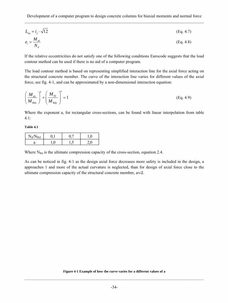
The load contour method is based on representing simplified interaction line for the axial force acting on the structural concrete member. The curve of the interaction line varies for different values of the axial force, see fig. 4-1, and can be approximated by a non-dimensional interaction equation:
1aa
dydx
Rdx Rdy
MMM M
⎛ ⎞⎛ ⎞+ =⎜ ⎟⎜ ⎟ ⎜ ⎟⎝ ⎠ ⎝ ⎠
(Eq. 4.9)
Where the exponent a, for rectangular cross-sections, can be found with linear interpolation from table 4.1:
Table 4.1
Where NRd is the ultimate compression capacity of the cross-section, equation 2.4.
As can be noticed in fig. 4-1 as the design axial force decreases more safety is included in the design, a approaches 1 and more of the actual curvature is neglected, than for design of axial force close to the ultimate compression capacity of the structural concrete member, a≈2.
Figure 4-1 Example of how the curve varies for a different values of a
Nd/NRd 0,1 0,7 1,0a 1,0 1,5 2,0
Development of a computer program to design concrete columns for biaxial moments and normal force _____________________________________________________________________________________
_____________________________________________________________________________________
-35-
So Eurocode suggests that the following criteria must be satisfied in the absence of an accurate cross-section design for biaxial moments.
1aa
dydx
Rdx Rdy
MMM M
⎛ ⎞⎛ ⎞+ ≤⎜ ⎟⎜ ⎟ ⎜ ⎟⎝ ⎠ ⎝ ⎠
(Eq. 4.10)
4.1 Results for design of the case study according to Eurocode Detailed calculations can be seen in Annex B.
The load combinations are:
The relative eccentricities for all the load combinations do not satisfy the conditions, equations 4.4.a and 4.4.b, so the load contour method is used with a as 1,07. a is approximately the same for all load combinations.
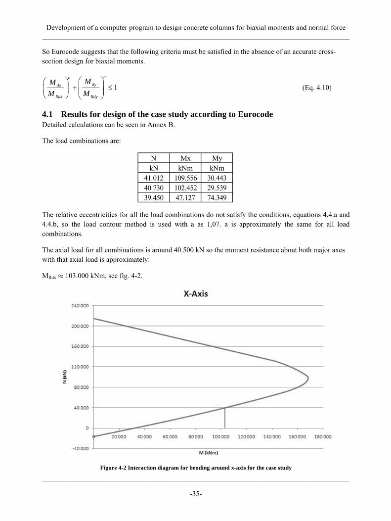
The axial load for all combinations is around 40.500 kN so the moment resistance about both major axes with that axial load is approximately:
MRdx ≈ 103.000 kNm, see fig. 4-2.
Figure 4-2 Interaction diagram for bending around x-axis for the case study
N Mx MykN kNm kNm
41.012 109.556 30.44340.730 102.452 29.53939.450 47.127 74.349

Development of a computer program to design concrete columns for biaxial moments and normal force _____________________________________________________________________________________
_____________________________________________________________________________________
-36-
MRdy ≈ 195.000 kNm, see fig. 4-3.
Figure 4-3 Interaction diagram for bending around y-axis for the case study
The results from equation 4.10 will then be:
or can be expressed graphically, see fig 4-4:
Figure 4-4 Simplified interaction line with the load contour method
LC 1 1,20LC 2 1,12LC 3 0,79
Development of a computer program to design concrete columns for biaxial moments and normal force _____________________________________________________________________________________
_____________________________________________________________________________________
-37-
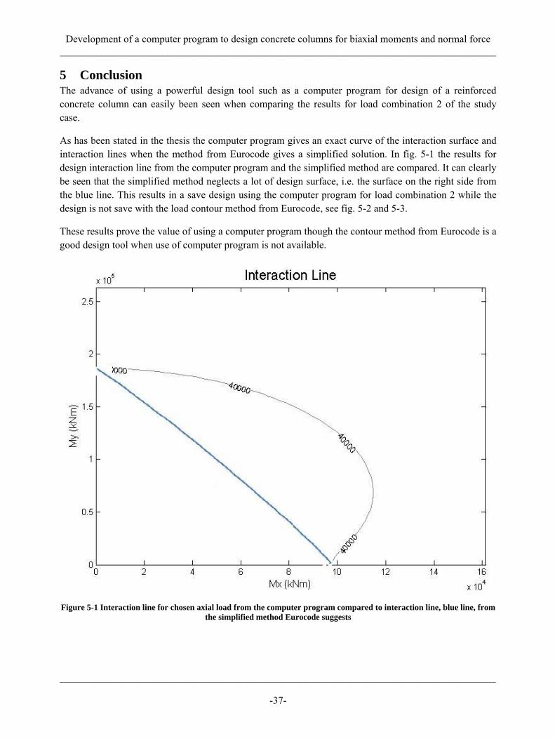
5 Conclusion The advance of using a powerful design tool such as a computer program for design of a reinforced concrete column can easily been seen when comparing the results for load combination 2 of the study case.
As has been stated in the thesis the computer program gives an exact curve of the interaction surface and interaction lines when the method from Eurocode gives a simplified solution. In fig. 5-1 the results for design interaction line from the computer program and the simplified method are compared. It can clearly be seen that the simplified method neglects a lot of design surface, i.e. the surface on the right side from the blue line. This results in a save design using the computer program for load combination 2 while the design is not save with the load contour method from Eurocode, see fig. 5-2 and 5-3.
These results prove the value of using a computer program though the contour method from Eurocode is a good design tool when use of computer program is not available.
Figure 5-1 Interaction line for chosen axial load from the computer program compared to interaction line, blue line, from the simplified method Eurocode suggests

Development of a computer program to design concrete columns for biaxial moments and normal force _____________________________________________________________________________________
_____________________________________________________________________________________
-38-
Figure 5-2 Interaction line from the computer program, requirements fulfilled – safe design
Figure 5-3 Interaction line from contour method in Eurocode, requirements not fulfilled – not safe design
Development of a computer program to design concrete columns for biaxial moments and normal force _____________________________________________________________________________________
_____________________________________________________________________________________
-39-
6 References
6.1 Literature BBK (2004). Boverkets handbok om betongkostruktioner. Boverket, Karskrona, Sweden.
EC2 (2004), Eurocode 2: Design of concrete structures – Part 1-1: General rules and rules for buildings, European Prestandard EN 1992-1-1-2004:E, European Committee for Standardisation TC 250, Brussels, Belgium.
Engström, Björn. (2004), Beräkning av betongkonstruktioner. Chalmer Tekniska Högskola, Gothenburg, Sweden.
Eugene J. O´Brien and Andrew S. Dixon. (1999), Reinforced and Prestressed Concrete Design: The Complete Process. Harlow: Longman Scientific & Technical, London, United Kingdom.
Gere, James M. (2004), Mechanics of materials, sixth edition. Thomson Learning, London, United Kingdom.
Isaksson, Tord and Mårtensson, Annike. (2008), Byggkonstruktion, Regel- och formelsamling. Studentlitteratur, Malmö, Sweden.
Park, Robert and Pauley, Thomas. (1975), Reinforced concrete structures. John Wiley & Sons, Inc., USA.
6.2 Computer programs AutoCAD 2009, Autodesk.
MathType (Version 6.6); Design Science.
Matlab R2008b (Version 7.7.0.471), The MathWorks.
Microsoft Office Excel 2007, Microsoft.
Microsoft Office Word 2007, Microsoft.
Microsoft Paint, Microsoft.

Development of a computer program to design concrete columns for biaxial moments and normal force _____________________________________________________________________________________
_____________________________________________________________________________________
-40-

Development of a computer program to design concrete columns for biaxial moments and normal force _____________________________________________________________________________________
_____________________________________________________________________________________
-41-
Annex A. Properties of plane areas
φ < φcrit
Zone 1: Zone 2: Zone 3:
1 11tan
tanb h ϕ
ϕ⎛ ⎞
= +⎜ ⎟⎝ ⎠
2 cosLbϕ
= 3 31tan
tanb h ϕ
ϕ⎛ ⎞
= +⎜ ⎟⎝ ⎠
1 11 2
h bA = 2 2 2A b h= ( )3 2 3
3 2h b b
A+
=
11
22 3
hhe = − 22 12 2
hhe h⎛ ⎞= − +⎜ ⎟⎝ ⎠
( )( )
3 2 33 1 2
2 3
22 3
h b bhe h hb b
⎛ ⎞+= − + +⎜ ⎟⎜ ⎟+⎝ ⎠

Development of a computer program to design concrete columns for biaxial moments and normal force _____________________________________________________________________________________
_____________________________________________________________________________________
-42-
φ > φcrit
Zone 1: Zone 2: Zone 3:
1 11tan
tanb h ϕ
ϕ⎛ ⎞
= +⎜ ⎟⎝ ⎠
2 sinBbϕ
= 3 31tan
tanb h ϕ
ϕ⎛ ⎞
= +⎜ ⎟⎝ ⎠
1 11 2
h bA = 2 2 2A b h= ( )3 2 3
3 2h b b
A+
=
11
22 3
hhe = − 22 12 2
hhe h⎛ ⎞= − +⎜ ⎟⎝ ⎠
( )( )
3 2 33 1 2
2 3
22 3
h b bhe h hb b
⎛ ⎞+= − + +⎜ ⎟⎜ ⎟+⎝ ⎠

Development of a computer program to design concrete columns for biaxial moments and normal force _____________________________________________________________________________________
_____________________________________________________________________________________
-43-
Annex B. Detailed calculations for biaxial moments according to Eurocode Material properties.
Concrete:
0,85 28,5 16, 21,5
cckcc
m
f MPaf MPaαγ
⋅= = =
Reinforcement:
390 339,11,15
ykst
m
f MPaf MPaγ
= = =
200.000 173.9131,15
skd
m
E MPaE MPaγ
= = =
Cross-section properties.
4000B mm= 2840b mm= 7800L mm=
6640l mm= 24000 7800 2840 6640 12.342.400A BL bl mm mm mm mm mm= − = ⋅ − ⋅ =
( ) ( )3 33 313 47800 4000 6640 2840
2,89 1012 12x
mm mm mm mmLB lbI mm⋅ − ⋅−
= = = ⋅
13 4
2
2,89 10 1530,912.342.400
xx
I mmi mmA mm
⋅= = =
( ) ( )3 33 313 44000 7800 2840 6640
8,89 1012 12y
mm mm mm mmBL blI mm⋅ − ⋅−
= = = ⋅
13 4
2
8,89 10 2683,812.342.400
yy
I mmi mmA mm
⋅= = =
12 1530,9 12 5303,1eq yB i mm mm= ⋅ = ⋅ =
12 2683,8 12 9296,9eq xL i mm mm= ⋅ = ⋅ =
Development of a computer program to design concrete columns for biaxial moments and normal force _____________________________________________________________________________________
_____________________________________________________________________________________
-44-
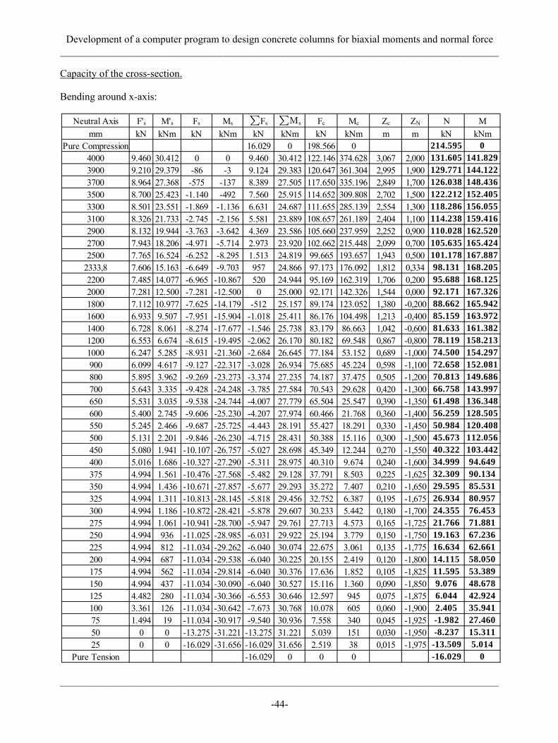
Capacity of the cross-section.
Bending around x-axis:
Neutral Axis F's M's Fs Ms ∑Fs ∑Ms Fc Mc Zc ZN N Mmm kN kNm kN kNm kN kNm kN kNm m m kN kNm
Pure Compression 16.029 0 198.566 0 214.595 04000 9.460 30.412 0 0 9.460 30.412 122.146 374.628 3,067 2,000 131.605 141.8293900 9.210 29.379 -86 -3 9.124 29.383 120.647 361.304 2,995 1,900 129.771 144.1223700 8.964 27.368 -575 -137 8.389 27.505 117.650 335.196 2,849 1,700 126.038 148.4363500 8.700 25.423 -1.140 -492 7.560 25.915 114.652 309.808 2,702 1,500 122.212 152.4053300 8.501 23.551 -1.869 -1.136 6.631 24.687 111.655 285.139 2,554 1,300 118.286 156.0553100 8.326 21.733 -2.745 -2.156 5.581 23.889 108.657 261.189 2,404 1,100 114.238 159.4162900 8.132 19.944 -3.763 -3.642 4.369 23.586 105.660 237.959 2,252 0,900 110.028 162.5202700 7.943 18.206 -4.971 -5.714 2.973 23.920 102.662 215.448 2,099 0,700 105.635 165.4242500 7.765 16.524 -6.252 -8.295 1.513 24.819 99.665 193.657 1,943 0,500 101.178 167.887
2333,8 7.606 15.163 -6.649 -9.703 957 24.866 97.173 176.092 1,812 0,334 98.131 168.2052200 7.485 14.077 -6.965 -10.867 520 24.944 95.169 162.319 1,706 0,200 95.688 168.1252000 7.281 12.500 -7.281 -12.500 0 25.000 92.171 142.326 1,544 0,000 92.171 167.3261800 7.112 10.977 -7.625 -14.179 -512 25.157 89.174 123.052 1,380 -0,200 88.662 165.9421600 6.933 9.507 -7.951 -15.904 -1.018 25.411 86.176 104.498 1,213 -0,400 85.159 163.9721400 6.728 8.061 -8.274 -17.677 -1.546 25.738 83.179 86.663 1,042 -0,600 81.633 161.3821200 6.553 6.674 -8.615 -19.495 -2.062 26.170 80.182 69.548 0,867 -0,800 78.119 158.2131000 6.247 5.285 -8.931 -21.360 -2.684 26.645 77.184 53.152 0,689 -1,000 74.500 154.297900 6.099 4.617 -9.127 -22.317 -3.028 26.934 75.685 45.224 0,598 -1,100 72.658 152.081800 5.895 3.962 -9.269 -23.273 -3.374 27.235 74.187 37.475 0,505 -1,200 70.813 149.686700 5.643 3.335 -9.428 -24.248 -3.785 27.584 70.543 29.628 0,420 -1,300 66.758 143.997650 5.531 3.035 -9.538 -24.744 -4.007 27.779 65.504 25.547 0,390 -1,350 61.498 136.348600 5.400 2.745 -9.606 -25.230 -4.207 27.974 60.466 21.768 0,360 -1,400 56.259 128.505550 5.245 2.466 -9.687 -25.725 -4.443 28.191 55.427 18.291 0,330 -1,450 50.984 120.408500 5.131 2.201 -9.846 -26.230 -4.715 28.431 50.388 15.116 0,300 -1,500 45.673 112.056450 5.080 1.941 -10.107 -26.757 -5.027 28.698 45.349 12.244 0,270 -1,550 40.322 103.442400 5.016 1.686 -10.327 -27.290 -5.311 28.975 40.310 9.674 0,240 -1,600 34.999 94.649375 4.994 1.561 -10.476 -27.568 -5.482 29.128 37.791 8.503 0,225 -1,625 32.309 90.134350 4.994 1.436 -10.671 -27.857 -5.677 29.293 35.272 7.407 0,210 -1,650 29.595 85.531325 4.994 1.311 -10.813 -28.145 -5.818 29.456 32.752 6.387 0,195 -1,675 26.934 80.957300 4.994 1.186 -10.872 -28.421 -5.878 29.607 30.233 5.442 0,180 -1,700 24.355 76.453275 4.994 1.061 -10.941 -28.700 -5.947 29.761 27.713 4.573 0,165 -1,725 21.766 71.881250 4.994 936 -11.025 -28.985 -6.031 29.922 25.194 3.779 0,150 -1,750 19.163 67.236225 4.994 812 -11.034 -29.262 -6.040 30.074 22.675 3.061 0,135 -1,775 16.634 62.661200 4.994 687 -11.034 -29.538 -6.040 30.225 20.155 2.419 0,120 -1,800 14.115 58.050175 4.994 562 -11.034 -29.814 -6.040 30.376 17.636 1.852 0,105 -1,825 11.595 53.389150 4.994 437 -11.034 -30.090 -6.040 30.527 15.116 1.360 0,090 -1,850 9.076 48.678125 4.482 280 -11.034 -30.366 -6.553 30.646 12.597 945 0,075 -1,875 6.044 42.924100 3.361 126 -11.034 -30.642 -7.673 30.768 10.078 605 0,060 -1,900 2.405 35.94175 1.494 19 -11.034 -30.917 -9.540 30.936 7.558 340 0,045 -1,925 -1.982 27.46050 0 0 -13.275 -31.221 -13.275 31.221 5.039 151 0,030 -1,950 -8.237 15.31125 0 0 -16.029 -31.656 -16.029 31.656 2.519 38 0,015 -1,975 -13.509 5.014
Pure Tension -16.029 0 0 0 -16.029 0
Development of a computer program to design concrete columns for biaxial moments and normal force _____________________________________________________________________________________
_____________________________________________________________________________________
-45-
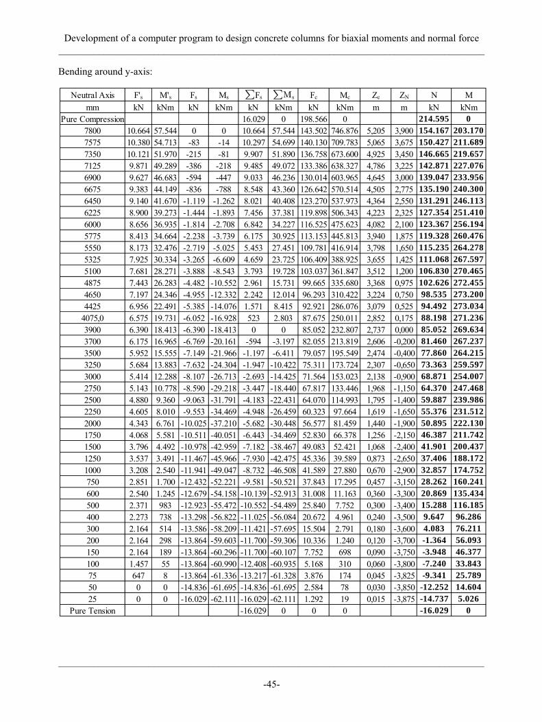
Bending around y-axis:
Neutral Axis F's M's Fs Ms ∑Fs ∑Ms Fc Mc Zc ZN N Mmm kN kNm kN kNm kN kNm kN kNm m m kN kNm
Pure Compression 16.029 0 198.566 0 214.595 07800 10.664 57.544 0 0 10.664 57.544 143.502 746.876 5,205 3,900 154.167 203.1707575 10.380 54.713 -83 -14 10.297 54.699 140.130 709.783 5,065 3,675 150.427 211.6897350 10.121 51.970 -215 -81 9.907 51.890 136.758 673.600 4,925 3,450 146.665 219.6577125 9.871 49.289 -386 -218 9.485 49.072 133.386 638.327 4,786 3,225 142.871 227.0766900 9.627 46.683 -594 -447 9.033 46.236 130.014 603.965 4,645 3,000 139.047 233.9566675 9.383 44.149 -836 -788 8.548 43.360 126.642 570.514 4,505 2,775 135.190 240.3006450 9.140 41.670 -1.119 -1.262 8.021 40.408 123.270 537.973 4,364 2,550 131.291 246.1136225 8.900 39.273 -1.444 -1.893 7.456 37.381 119.898 506.343 4,223 2,325 127.354 251.4106000 8.656 36.935 -1.814 -2.708 6.842 34.227 116.525 475.623 4,082 2,100 123.367 256.1945775 8.413 34.664 -2.238 -3.739 6.175 30.925 113.153 445.813 3,940 1,875 119.328 260.4765550 8.173 32.476 -2.719 -5.025 5.453 27.451 109.781 416.914 3,798 1,650 115.235 264.2785325 7.925 30.334 -3.265 -6.609 4.659 23.725 106.409 388.925 3,655 1,425 111.068 267.5975100 7.681 28.271 -3.888 -8.543 3.793 19.728 103.037 361.847 3,512 1,200 106.830 270.4654875 7.443 26.283 -4.482 -10.552 2.961 15.731 99.665 335.680 3,368 0,975 102.626 272.4554650 7.197 24.346 -4.955 -12.332 2.242 12.014 96.293 310.422 3,224 0,750 98.535 273.2004425 6.956 22.491 -5.385 -14.076 1.571 8.415 92.921 286.076 3,079 0,525 94.492 273.034
4075,0 6.575 19.731 -6.052 -16.928 523 2.803 87.675 250.011 2,852 0,175 88.198 271.2363900 6.390 18.413 -6.390 -18.413 0 0 85.052 232.807 2,737 0,000 85.052 269.6343700 6.175 16.965 -6.769 -20.161 -594 -3.197 82.055 213.819 2,606 -0,200 81.460 267.2373500 5.952 15.555 -7.149 -21.966 -1.197 -6.411 79.057 195.549 2,474 -0,400 77.860 264.2153250 5.684 13.883 -7.632 -24.304 -1.947 -10.422 75.311 173.724 2,307 -0,650 73.363 259.5973000 5.414 12.288 -8.107 -26.713 -2.693 -14.425 71.564 153.023 2,138 -0,900 68.871 254.0072750 5.143 10.778 -8.590 -29.218 -3.447 -18.440 67.817 133.446 1,968 -1,150 64.370 247.4682500 4.880 9.360 -9.063 -31.791 -4.183 -22.431 64.070 114.993 1,795 -1,400 59.887 239.9862250 4.605 8.010 -9.553 -34.469 -4.948 -26.459 60.323 97.664 1,619 -1,650 55.376 231.5122000 4.343 6.761 -10.025 -37.210 -5.682 -30.448 56.577 81.459 1,440 -1,900 50.895 222.1301750 4.068 5.581 -10.511 -40.051 -6.443 -34.469 52.830 66.378 1,256 -2,150 46.387 211.7421500 3.796 4.492 -10.978 -42.959 -7.182 -38.467 49.083 52.421 1,068 -2,400 41.901 200.4371250 3.537 3.491 -11.467 -45.966 -7.930 -42.475 45.336 39.589 0,873 -2,650 37.406 188.1721000 3.208 2.540 -11.941 -49.047 -8.732 -46.508 41.589 27.880 0,670 -2,900 32.857 174.752750 2.851 1.700 -12.432 -52.221 -9.581 -50.521 37.843 17.295 0,457 -3,150 28.262 160.241600 2.540 1.245 -12.679 -54.158 -10.139 -52.913 31.008 11.163 0,360 -3,300 20.869 135.434500 2.371 983 -12.923 -55.472 -10.552 -54.489 25.840 7.752 0,300 -3,400 15.288 116.185400 2.273 738 -13.298 -56.822 -11.025 -56.084 20.672 4.961 0,240 -3,500 9.647 96.286300 2.164 514 -13.586 -58.209 -11.421 -57.695 15.504 2.791 0,180 -3,600 4.083 76.211200 2.164 298 -13.864 -59.603 -11.700 -59.306 10.336 1.240 0,120 -3,700 -1.364 56.093150 2.164 189 -13.864 -60.296 -11.700 -60.107 7.752 698 0,090 -3,750 -3.948 46.377100 1.457 55 -13.864 -60.990 -12.408 -60.935 5.168 310 0,060 -3,800 -7.240 33.84375 647 8 -13.864 -61.336 -13.217 -61.328 3.876 174 0,045 -3,825 -9.341 25.78950 0 0 -14.836 -61.695 -14.836 -61.695 2.584 78 0,030 -3,850 -12.252 14.60425 0 0 -16.029 -62.111 -16.029 -62.111 1.292 19 0,015 -3,875 -14.737 5.026
Pure Tension -16.029 0 0 0 -16.029 0
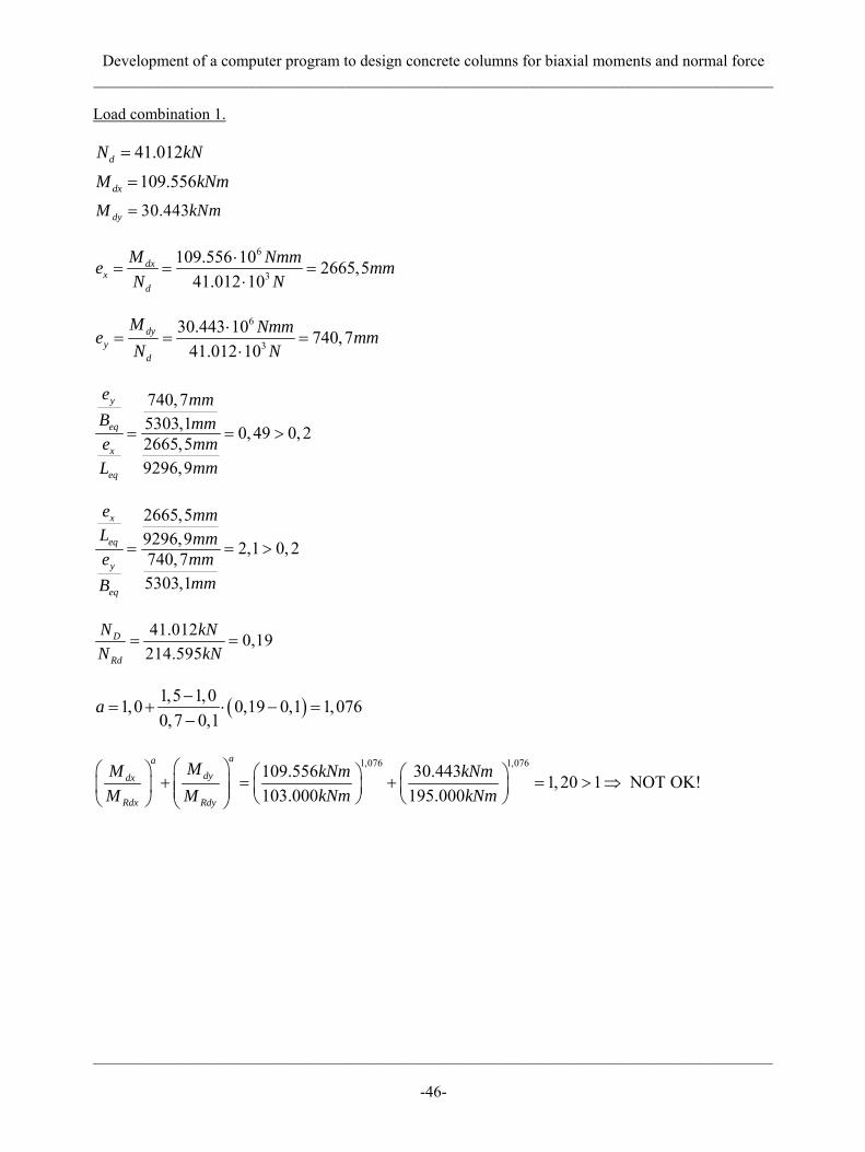
Development of a computer program to design concrete columns for biaxial moments and normal force _____________________________________________________________________________________
_____________________________________________________________________________________
-46-
Load combination 1.
41.012dN kN=
109.556dxM kNm=
30.443dyM kNm=
6
3
109.556 10 2665,541.012 10
dxx
d
M Nmme mmN N
⋅= = =
⋅
6
3
30.443 10 740,741.012 10
dyy
d
M Nmme mmN N
⋅= = =
⋅
740,75303,1 0, 49 0, 22665,59296,9
y
eq
x
eq
e mmB mme mm
mmL
= = >
2665,59296,9 2,1 0, 2740,75303,1
x
eq
y
eq
e mmL mme mm
mmB
= = >
41.012 0,19214.595
D
Rd
N kNN kN
= =
( )1,5 1,01,0 0,19 0,1 1,0760,7 0,1
a −= + ⋅ − =
−
1,076 1,076109.556 30.443 1, 20 1 NOT OK!103.000 195.000
aadydx
Rdx Rdy
MM kNm kNmM M kNm kNm
⎛ ⎞⎛ ⎞ ⎛ ⎞ ⎛ ⎞+ = + = > ⇒⎜ ⎟⎜ ⎟ ⎜ ⎟ ⎜ ⎟⎜ ⎟ ⎝ ⎠ ⎝ ⎠⎝ ⎠ ⎝ ⎠
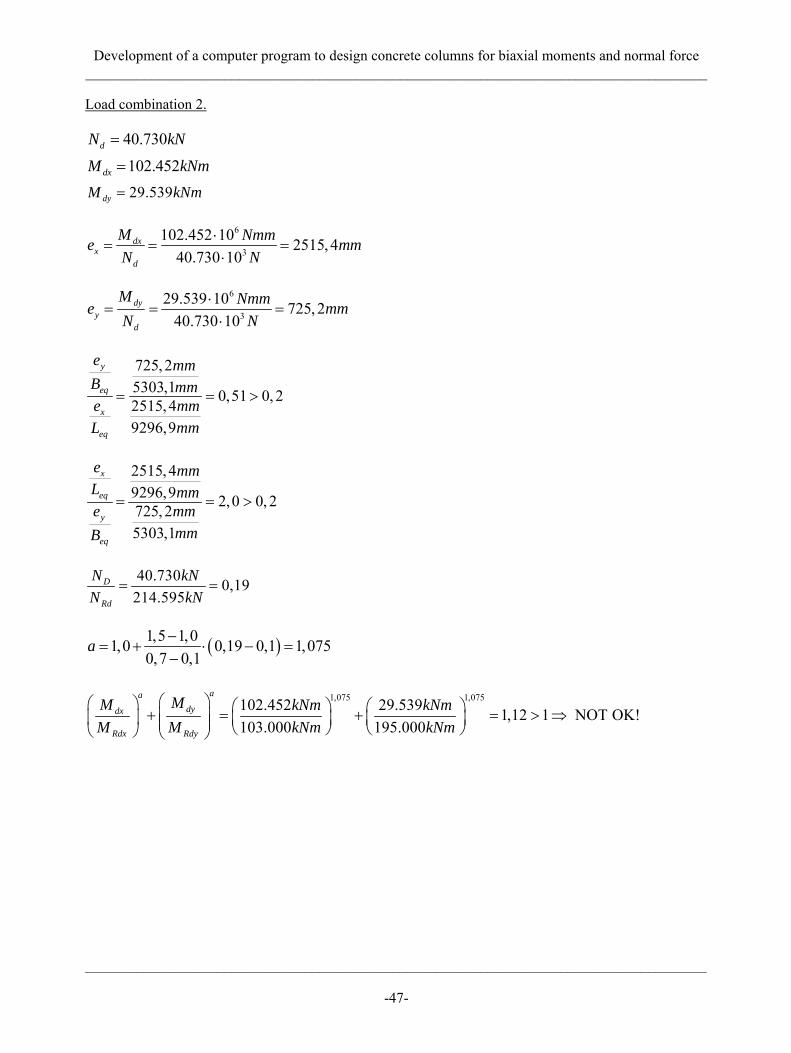
Development of a computer program to design concrete columns for biaxial moments and normal force _____________________________________________________________________________________
_____________________________________________________________________________________
-47-
Load combination 2.
40.730dN kN=
102.452dxM kNm=
29.539dyM kNm=
6
3
102.452 10 2515,440.730 10
dxx
d
M Nmme mmN N
⋅= = =
⋅
6
3
29.539 10 725,240.730 10
dyy
d
M Nmme mmN N
⋅= = =
⋅
725,25303,1 0,51 0, 22515, 49296,9
y
eq
x
eq
e mmB mme mm
mmL
= = >
2515, 49296,9 2,0 0, 2725, 25303,1
x
eq
y
eq
e mmL mme mm
mmB
= = >
40.730 0,19214.595
D
Rd
N kNN kN
= =
( )1,5 1,01,0 0,19 0,1 1,0750,7 0,1
a −= + ⋅ − =
−
1,075 1,075102.452 29.539 1,12 1 NOT OK!103.000 195.000
aadydx
Rdx Rdy
MM kNm kNmM M kNm kNm
⎛ ⎞⎛ ⎞ ⎛ ⎞ ⎛ ⎞+ = + = > ⇒⎜ ⎟⎜ ⎟ ⎜ ⎟ ⎜ ⎟⎜ ⎟ ⎝ ⎠ ⎝ ⎠⎝ ⎠ ⎝ ⎠

Development of a computer program to design concrete columns for biaxial moments and normal force _____________________________________________________________________________________
_____________________________________________________________________________________
-48-
Load combination 3.
39.450dN kN=
47.127dxM kNm=
74.349dyM kNm=
6
3
47.127 10 1194,639.450 10
dxx
d
M Nmme mmN N
⋅= = =
⋅
6
3
74.349 10 1884,639.450 10
dyy
d
M Nmme mmN N
⋅= = =
⋅
1884,65303,1 2,77 0, 21194,69296,9
y
eq
x
eq
e mmB mme mm
mmL
= = >
2515, 49296,9 0,36 0, 2725, 25303,1
x
eq
y
eq
e mmL mme mm
mmB
= = >
39.450 0,18214.595
D
Rd
N kNN kN
= =
( )1,5 1,01,0 0,18 0,1 1,0700,7 0,1
a −= + ⋅ − =
−
1,070 1,07047.127 74.349 0,79 1 OK103.000 195.000
aadydx
Rdx Rdy
MM kNm kNmM M kNm kNm
⎛ ⎞⎛ ⎞ ⎛ ⎞ ⎛ ⎞+ = + = < ⇒⎜ ⎟⎜ ⎟ ⎜ ⎟ ⎜ ⎟⎜ ⎟ ⎝ ⎠ ⎝ ⎠⎝ ⎠ ⎝ ⎠