DEVELOPMENT OF A COMPRESSED NATURAL GAS (CNG)...
21
DEVELOPMENT OF A COMPRESSED NATURAL GAS (CNG) MIXER FOR A TWO STROKE INTERNAL COMBUSTION ENGINE DEVARAJAN A/L RAMASAMY UNIVERSITI TEKNOLOGI MALAYSIA
-
Upload
nguyenkhuong -
Category
Documents
-
view
212 -
download
0
Transcript of DEVELOPMENT OF A COMPRESSED NATURAL GAS (CNG)...

DEVELOPMENT OF A COMPRESSED NATURAL GAS (CNG) MIXER FOR A
TWO STROKE INTERNAL COMBUSTION ENGINE
DEVARAJAN A/L RAMASAMY
UNIVERSITI TEKNOLOGI MALAYSIA
DEVELOPMENT OF A COMPRESSED NATURAL GAS (CNG) MIXER FOR A
TWO STROKE INTERNAL COMBUSTION ENGINE
DEVARAJAN A/L RAMASAMY
A thesis submitted in fulfilment of the
requirements for the award of the degree of
Masters of Engineering (Mechanical)
Fakulti Kejuruteraan Mekanikal
Universiti Teknologi Malaysia
OCTOBER 2005

v
ABSTRACT
Compressed Natural Gas (CNG) has been accepted widely as an alternative to
gasoline. More importantly the use of CNG in two stroke engines will drastically
reduce the high emission output from these engines as these engines are widely used
around the world. A conversion kit is used to apply the fuel in engines. A bi-fuel
conversion system converts engines without much modification to other systems.
They are normally produced for four stroke application. This kit has to be studied to
be modified for two stroke application. The part that connects the engine to the kit is
called a gaseous fuel mixer. This part mixes the air and fuel due to its venturi shape.
A mixer provides fuel suction at different engine speeds due to pressure difference at
the throat. The optimisation of the throat is important as a small throat will cause
poor performance at high speeds while a large throat will reduce fuel suction. The
smaller throat size creates higher velocity and lower pressure. This low pressure
creates fuel suction into the mixer. The mixer was designed for a two stroke engine
air flow. Computer aided design (CAD) and computational fluid dynamic (CFD)
software were used as a tool for the design. The design is optimised for inlet and
outlet angles, number and size of the hole at the throat circumference and also the
throat size. The prototype design was manufactured based on optimised dimensions
of the mixer that were obtained from CFD analysis. The mixer was validated to show
that the CFD analysis was correct. Testing apparatus were used to do the validation.
The apparatus consists of a laminar flow element (LFE), a smoke generator, a digital
manometer and a gaseous flow meter. It was used to validate the flow pattern,
pressure drop from the mixer and the air fuel ratio given by the mixer.

vi
ABSTRAK
Gas Asli Termampat (CNG) telah diperaku i sebagai satu alternatif kepada
petrol. Penggunaan gas in dalam enjin dua lejang mampu mengurangkan pengeluaran
pencemaran tinggi dari enjin ini. Ini kerana penggunaan enjin dua lejang adalah
banyak di dunia. Bahan api ini digunakan pada engine melalui kit penukaran.
Penukaran enjin petrol ke CNG perlu dilakukan dengan modifikasi kecil pada enjin
asal. Oleh itu, kit penukar CNG dwi-bahanapi digunakan. Unit ini dibuat lazimnya
untuk enjin empat lejang, oleh itu, ia perl u dikaji bagi penggunaan dalam enjin dua
lejang. Bahagian pada alat ini yang bersambung kepada enjin dinamakan sebagai
pencampur bahanapi bergas. Ia menyebabkan gas bercampur pada bahagian yang
berbentuk venturi. Pencampur ini memberikan sedutan gas kepada enjin pada halaju
enjin yang berbeza disebabkan perbezaan tekanan pada bahagian yang dipanggil
leher. Ubahsuai leher adalah penting bagi operasi alat ini. Ubahsuai leher adalah
perlu kerana leher yang kecil akan menyebabkan prestasi enjin yang rendah pada
kelajuan tinggi manakala leher yang besar tidak dapat memberi sedutan gas yang
diperlukan. Tekanan rendah menyebabkan sedutan pada pencampur ini. Pencampur
direkabentuk untuk aliran udara pada enjin dua lejang. Rekabentuk berbantukan
computer (CAD) dan Dinamik Bendalir berbantukan computer (CFD) digunakan
sebagai alat rekabentuk. Rekabentuk pencampur diubahsuai dengan menggunakan
CFD pada sudut masukan dan keluaran, bila ngan lubang dan saiz lubang pada leher
serta saiz leher itu sendiri. Prototaip dibuat berdasarkan dimensi pencampur yang
diperolehi daripada analisis CFD. Untuk membuktikan analisis CFD pengesahan
telah dilakukan. Peralatan ujikaji telah digunakan untuk melakukan pengesahan ini.
Ia terdiri daripada elemen aliran laminar (LFE), penghasil asap, manometer digital
dan meter aliran gas. Peralatan ini digunakan bagi tujuan pengesahan bentuk aliran,
kejatuhan tekanan dan nisbah udara kepada bahan api yang diberi oleh pencampur
ini.

vii
CONTENTS
CHAPTER TITLE PAGE
TITLE i
DECLARATION ii
DEDICATION iii
ACKNOWLEDGEMENT iv
ABSTRACT v
ABSTRAK vi
CONTENTS vii
LIST OF TABLES xi
LIST OF FIGURES xii
LIST OF APPENDICES xiv
LIST OF SYMBOLS xv
1 INTRODUCTION 1
1.1 Problem Statement 2
1.2 Objectives 3
1.3 Scope 3
1.4 Methodology 3

viii
2 LITERATURE REVIEW 5
2.1 Two Stroke Engine 5
2.2 CNG as Fuel for Two Stroke Engines 6
2.2.1 CNG as an Alternative Fuel 7
2.2.2 Combustion Characteristics of CNG 10
2.2.3 Emission Reduction from CNG Usage in
Two Stroke Engines 11
2.2.4 Other Issues Regarding CNG Usage 13
2.3 CNG Mixer 14
2.3.1 Current Trends in CNG Mixer Design 15
2.3.2 Sizing of the Mixer Throat 18
2.3.3 Pressure Drop in the Mixer 19
2.3.4 CNG Mixer and Engine Conversion Kits 23
2.4 Summary of Literature Review 24
3 DESIGN OF A VENTURI BURNER MIXER 25
3.1 Conceptual Design 26
3.2 Procedure of Mixer Design 28
3.2.1 Initial Throat Size 29
3.2.2 CFD Simulations of the Mixer 30
3.2.3 Inlet and Outlet Angles of the Mixer 34
3.2.4 Number of Holes at Throat Circumference 36
3.2.5 Size of Hole at Throat Circumference 37
3.2.6 Throat Size Optimisation 37
3.3 Prototyping the Mixer 38
3.4 Validating the Mixer Design 39
3.4.1 Testing Apparatus 39
3.4.2 Testing Procedure 42
3.4.2.1 Smoke Mixing in Mixer 43
3.4.2.2 AF Ratio Test 43

ix
3.4.2.3 Pressure Drop Test 46
4 RESULT AND DISCUSSION 47
4.1 Designing of the Mixer 47
4.1.1 Initial Throat Size 47
4.1.2 CFD Simulation of the Mixer 48
4.1.3 Inlet and Outlet Angles of the Mixer 48
4.1.4 Number of Holes at Throat Circumference 52
4.1.5 Size of Hole at Throat Circumference 56
4.1.6 Throat Size Optimisation 58
4.2 Prototyping the Mixer 63
4.3 Validating the Mixer Design 65
4.3.1 Smoke Mixing in Perspex Prototype 65
4.3.2 AF ratio Testing of Mixer 67
4.3.3 Pressure Drop Testing of Mixer 69
5 CONCLUSION AND RECOMMENDATION 72
5.1 Conclusion 72
5.3 Recommendation 73
REFERENCES 74
APPENDICES 77
Appendix A 77
Appendix B 79

x
Appendix C 109
Appendix D 117
Appendix E 125
Appendix F 128

xi
LIST OF TABLES
TABLE NO. TITLE PAGE
2.1 Energy content of alternative fuels relative to petrol
and diesel 8
2.2 Proven natural gas reserves 8
2.3 Average natural gas composition in Malaysia 9
2.4 Methane gas properties 10
2.5 Typical 2-stroke emissions 12
2.6 Current regulation that is available for two-stroke
engines 12
2.7 Fuel price 13
3.1 Specification of the analysed engine 29
3.2 Properties of air 33
5.1 Specification of the mixer designed 73

xii
LIST OF FIGURES
FIGURE NO. TITLE PAGES
1.1 Methodology 4
2.1 Operation of a two stroke engine 6
2.2 Type of CNG mixers currently being used in the market 15
2.3 Power test results for different mixer designs 16
2.4 Venturi upstream of the carburettor 18
2.5 Mixer after throttle in intake system of injection engine. 18
2.6 Schematic plot of velocity and pressure across a venturi 20
2.7 Pressure profile during intake stroke of an engine 21
2.8 Pressure drop in air cleaner and intake manifold 22
3.1 Methodology for designing the CNG mixer 25
3.2 The concept models 27
3.3 Proposed shape of the mixer 28
3.4 Location of throat diameter 30
3.5 Simulation steps for each simulation 32
3.6 Overall simulation stages done on the mixer 34
3.7 Simulation model for inlet and outlet angles 35
3.8 Schematic diagram of flow test rig to measure air flow 40
3.9 Schematic of smoke generator connected to test rig 41
3.10 Schematic diagram of pressure measurement 42
4.1 Pressure plot along the centre line of the mixer at different
inlet and outlet angles 49
4.2 Lowest pressure at the throat diffuser wall 50
4.3 Pressure ratios of each model inlet and outlet angle changes 51
4.4 Eight holes mixer model 53
4.5 Ten holes mixer model 54

xiii
4.6 Twelve holes mixer model 55
4.7 Effect of AF ratio on hole sizes at throat circumference
at all speed range 57
4.8 Effect of throat diameter size on air fuel ratio 60
4.9 Simulation pressure drop due to different throat size
at all engine speed 62
4.10 Perspex model for flow testing 63
4.11 Assembled view of Aluminium mixer 64
4.12 Components of Aluminium mixer 64
4.13 Simulation of smoke at 1000 rpm, 2000 rpm and 3000 rpm
air speed 66
4.14 Experiment and simulation results of AF ratio 68
4.15 Simulations and experiment pressure drop 71

xiv
LIST OF APPENDICES
APPENDIX TITLE PAGES
A Thesis Gantt Chart 77
B CFD Analysis 79
C Apparatus and Experiments 109
D Technical Drawings 117
E Material Selection 125
F Mesh Independant Analysis 128

xv
LIST OF SYMBOLS
AF Air fuel ratio -
1A Area in inlet m2
2A Area at throat m2
C Viscosity constant -
Cv Specific Heat J/kgK
Dr Delivery ratio -
HL Losses in pipe Pa
k Turbulent kinetic energy J/kg
1m Inlet mass flow rate kg/s
N Engine speed rpm
aQ Volumetric air flow rate m3/s
1Q Measured flow rate m3/s
2Q Actual flow rate m3/s
atmp Atmospheric pressure Pa
QH Heat source per unit volum e J/m 3
qi Diffusive heat flux J/s
Si Mass-d istributed external force per unit mass N/kg
U Fluid velocity m/s
1v Velocity at inlet m/s
2v Velocity at throat m/s
p Pressure drop Pa
airP Pressure drop in the air cleaner Pa
uP Intake pressure drop upstream Pa
thrP Pressure drop across throttle Pa
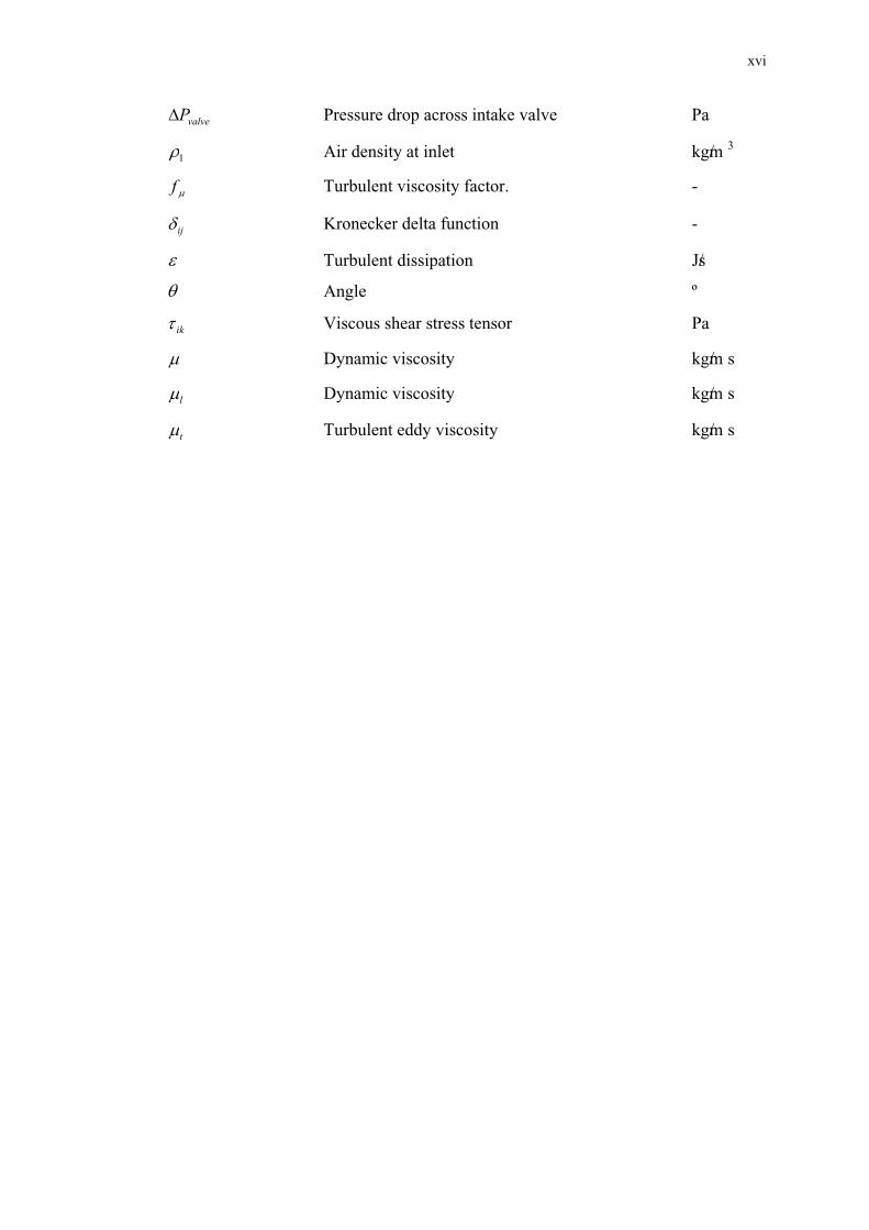
xvi
valveP Pressure drop across intake valve Pa
1 Air density at inlet kg/m 3
f Turbulent viscosity factor. -
ij Kronecker delta function -
Turbulent dissipation J/s
Angle º
ik Viscous shear stress tensor Pa
Dynamic viscosity kg/m s
l Dynamic viscosity kg/m s
t Turbulent eddy viscosity kg/m s

CHAPTER 1
INTRODUCTION
Current trends in the automotive industry are ever changing especially
regarding the usage of alternative fuels. The search for the best alternative fuel that
produces the least amount of emission has sparked concerns to many researchers.
Maxwell (1995) stated that many studies on alternative fuel have been carried out
and researchers are looking at natural gas, liquefied petroleum gas (LPG), methanol,
ethanol, and hydrogen. All of these fuels have their advantages and disadvantages
which are cost, availability, environmental impact, usage in vehicle, safety and the
acceptance by consumers.
Current fuel price inflation and also current oil crisis, drastic moves were
taken by many countries to reduce petroleum usage and finding other alternatives to
its usage. In developing countries, the concern of finding alternative fuels has
started and already had become an issue. With gas reserves three times more than
petroleum oil, Malaysia is increasingly turning its attention towards natural gas. The
national petroleum company of Malaysia, PETRONAS has embarked on the
Natural Gas for Vehicles (NGV) program where NGV dispensing facilities are
available at some selected PETRONAS service stations, located in high traffic
density areas of Kuala Lumpur and Johor Bahru. The government support for the
NGV program was seen in 25% reduction on car road tax for using NGV as well as
requiring new taxis in the Klang Valley to use CNG by engine conversion systems.

2
In automotive applications, natural gas can be used in three forms based on
how the natural gas is stored. One of the most popular forms of natural gas is the
compressed natural gas (CNG), which is natural gas in pressurised form. The other
least popular methods of obtaining natural are liquefied natural gas and the
absorption natural gas.
CNG is a good alternative to petrol and diesel. Consumers would easily
accept this form of alternative as it has low operational cost due to subsidised price
and its usage could provide cleaner engine emissions. The main reason behind CNG
fuel being cleaner is that natural gas is principally comprise of 90% methane, which
is the simplest form of hydrocarbon. Even so, the CNG fuel available today still
lack in some qualities compared to petroleum fuel. For example, CNG fuelled
engines normally possess lower engine performance compared to petrol.
The main reason is that CNG fuelling systems creates a lot of losses in
terms of volumetric efficiency. This happens as CNG must be supplied to the
engine through a mixing device before the mixture of CNG and air is drawn into the
engine. This causes less fuel in the combustion chamber and reduces volumetric
efficiency. Currently petrol fuelled engine are converted into a CNG fuelled engine
by means of a fuel mixing device.
1.1 Problem Statement
Currently, there are no specific CNG mixers specifically designed for two
stroke engines in the market. All of the conversion kits that are available for four
stroke engines only. A proper CNG mixer should be designed for two stroke engine
application. A supercharged 150 cc two stroke engine has been chosen for CNG
conversion. Direct usage of a conventional four stroke engine CNG mixer for two
stroke engines is not possible as they are too large a size for a small two stroke
engine air requirements. The design of the mixer has to consider the whole range of
engine operating condition in order to provide a complete view of its performance.

3
The existing four stroke engine CNG mixers are usually not properly refined
and optimised to enable good air fuel mixing. In addition, the efficiency of the
current mixer design is also an issue as it is designed for simplicity which only
offers practicality but lack in efficient air flow performance throughout the engine
speed. Therefore, a straight forward conversion is not possible.
1.2 Objectives
The objectives of the study are as follows:
1) To design a venturi burner type CNG mixer for a two stroke engine
according to the engine’s air requirement using CFD.
2) To fabricate the optimised prototype of the CNG mixer and test it on a
flow bench machine.
1.3 Scope
The scopes of the research are as follows:
1) Preliminary design of the CNG mixer.
2) Optimising the CNG mixer design using CFD as a design tool .
3) Fabrication of the prototype CNG mixer.
4) Testing and validation of the CNG mixer design.
1.4 Methodology
A general methodology was followed in the research as indicated in the flow
chart as shown in Figure 1.1:

4
Start
Literature review
Concept design
Designing of mixer
Figure 1.1 Methodology
Prototyping the mixer
Meet design criteria
No
Yes
Validating the mixer design
End

REFERENCES
Andreas N. Alexandrou (2001). Principles of Fluid Mechanics. Prentice Hall. New
Jersey.
Baert R. S. G., Beckman D. E., Veen A. (1999). Efficient EGR technology for future
HD diesel engine emission targets. TNO Road Vehicles Research Institute.
SAE 1999-01-0837.
Bryan Willson. (2002). Direct Injection as a Retrofit Strategy for Reducing
Emissions from 2-Stroke Cycle Engines in Asia. Hong Kong.
Ferguson, C.R (2001). Internal Combustion Engines- Applied Thermo-sciences. John
Wiley & Sons. Canada.
Gan L.M., (2003). Design and Development of Two Stroke Engine Using Blower
Mechanism. UTM, Thesis.
Gas Malaysia Sdn. Bhd. (2003). Natural Gas in Malaysia. Gas Malaysia
Heywood J.B (1988). Internal Combustion Engines Fundamentals, Mc Graw Hill
International Edition. Automotive Technologies Series
Jitendra (Jitu) Shah, N.Harshadeep (2001), Urban Pollution from Two Stroke Engine
Vehicles in Asia, Regional Workshop on Reduction of Emissions from 2-3
Wheelers, September 5-7, 2001– Hanoi, Vietnam.
Landirenzo, (2003). TN-SIC CNG Regulators. Installation Manual. Landirenzo
S.p.A. Italy
Lenz, H.P, (1992). Mixture Formation in Spark-Ignition Engines. SAE Inc. New
York.
Luiz Henrique Borges, Carlos Hollnagel and Wilson Muraro. (1996). Development of
Mercedes-Benz Natural Gas Engine M 366 LAG with a Lean Burn System.
SAE Brasil 1996. 962378 E
Maxwell T.T. and Jones J.C. (1995). Alternative Fuels: Emissions, Economics and
Performance. USA Society of Automotive Engineers: SAE Inc.

75
Mardani Ali Sera, Rosli Abu Bakar, Sin Kwan Leong. (2003). CNG Engine
Performance Improvement Strategy through Advanced Intake System.
Universiti Teknologi Malaysia. JSAE 20030229. SAE 2001-01-1937. Japan.
Mikio Furuyama, Bo Yan Xu. (1998). Mixing Flow Phenomena of Natural Gas and
Air in the Mixer of a CNG Vehicle. SAE 981391. Chiba University. Japan.
Mohamed Maurie Bundu. (1998). Investigation of the Performance of A Spark
Ignition Engine with Gaseous Fuels. Dalhouse University. Canada
Poulton M.L. (1994). Alternative Fuels for Road Vehicles. Computational Mechanics
Publications. Southamton. UK and Boston. USA. Pg 99-121.
Rosli Abu Bakar, Azhar Abdul Aziz and Mardani Ali Sera. (2002a). Effect of Air
Fuel Mixer Design on Engine Performance and Exhaust Emission Of A
CNG Fuelled Vehicles, 2nd World Engineering Congress Sarawak,
Malaysia,22-25 July 2002
Rosli Abu Bakar, Mardani Ali Sera, Sin Kwan Leong. (2002b). Design and
Development of New Compressed Natural Gas (CNG) Engine. IRPA Vot
72351. UTM.
Rosli Abu Bakar, Devarajan Ramasamy, Gan Leong Ming. (2004). Design of
Compressed Natural Gas (CNG) Mixer Using Computational Fluid
Dynamics. 2nd BSME-ASME International Conference on Thermal
Engineering. 2-4 January 2004. Dhaka
Rosli Abu Bakar, Devarajan Ramasamy, Chiew Chen Wee, (2003). Effects of Port
Sizes in Scavenging Process on New Two-Stroke Engine Using Numerical
Analysis. 3rd International Conference on Numerical Analysis in Engineering,
Batam View Beach Resort, 13-15 March.
Sierra Instruments, (1994). Top-Trak Mass Flow Meters. Instruction manual.
California. USA.
Taib Iskandar Mohamad, Mark Jermy, Matthew Harrison, (2003).Direct Injection of
Compressed Natural Gas in Spark Ignition Engines. ICAST 2003.
Willard W. Pulkrabek, (1997). Engineering Fundamentals of the Internal
Combustion Engine. Prentice Hall.
Yeap Beng Hi, Azeman Mustafa, Zulkefli Yaacob. (2002). Computational
Investigation of Air-Fuel Mixing System for Natural Gas Powered
Motorcycle. 6th Asia-Pacific International Symposium on Combustion and
Energy Utilization 20 – 22 May 2002, Kuala Lumpur

76
ISBN 983-52-0244-3
Yusoff Ali and Zailani Muhammad (2003). The Issues Promotion of the Use of
Natural Gas in Automotive the New Trend. ICAST 2003.