LIGO-G1200709-v3 Advanced LIGO 5 July 2012 David Shoemaker For the LIGO Scientific Collaboration.
Upload
phillip-riceCategory
view
226download
0
Development of a CO2 laser machine for pulling and welding of silica fibres and
ribbons
D. Crooks for the GEO 600 collaboration
Aspen January 2005LIGO-G050024-00-Z

Aspen January 2005 2
Isolation of test masses: mission Provide isolation of the test masses from seismic noise
whilst minimising thermal noise seismic noise:
ground motion inversely proportional to frequency squared: seismic noise important below ~ 50 Hz
thermal noise:most significant noise source in current detectors at low frequency end of operating range (~ 50 Hz to a few hundred Hz)
GEO 600

Aspen January 2005 3
Multiple pendulum suspensions with low loss final stage
Isolation from seismic noise: Multiple pendulum suspensions, cantilever steel blades
e.g. GEO 600 triple pendulum suspensions (isolation 1/f2 per stage) Minimise thermal noise:
Make final stage of low loss material e.g. GEO 600
Each stage has pendulum, violin and test mass modes of vibration
Quality Factor, Q = 1/(0)
(0) is mechanical dissipation or loss
want low (0), high Q
displacementThermal
High loss / low Q
Detection band
Pendulum mode internal modeof test mass
frequency (f)
Low loss / high Q
Aspen January 2005 4
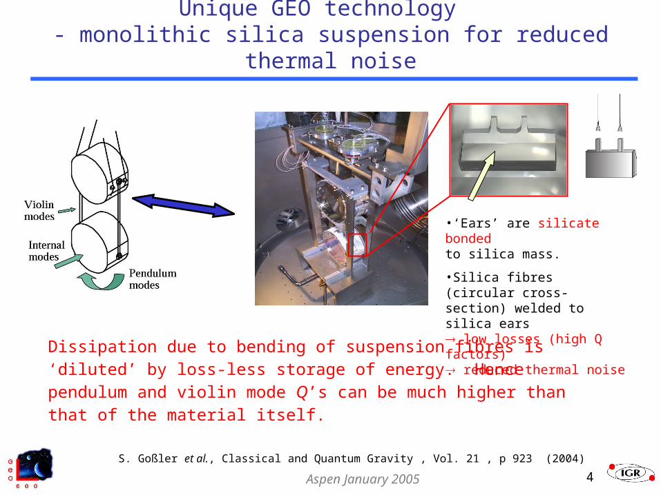
Unique GEO technology - monolithic silica suspension for reduced thermal noise
Dissipation due to bending of suspension fibres is ‘diluted’ by loss-less storage of energy. Hence pendulum and violin mode Q’s can be much higher than that of the material itself.
•‘Ears’ are silicate bonded to silica mass.
•Silica fibres (circular cross-section) welded to silica ears low losses (high Q factors) reduced thermal noise
S. Goßler et al., Classical and Quantum Gravity , Vol. 21 , p 923 (2004)

Aspen January 2005 5
GEO 600 silica suspension fibres – fabrication & welding technique
Circular fibres pulled using oxy-hydrogen flame pulling machine. Manual flame welding.
Successfully installed in GEO 600 late 2002.
Limitations Conductive/convective heating
Vaporisation of material on outer surface
Surface defects/contamination by combustion products can limit strength
Shape control - limited Unsophisticated - melt and pull before
silica cools down Increased noise couplings, limited
performance Reproducibility - limited
VIDEO CLIP OF FLAME PULLING OF RIBBON by A. Heptonstall
Picture: S. Goßler
Aspen January 2005 6
Improved silica fibre technology for advanced room temperature detectors
Advanced detectors require higher specification fibres than GEO 600 – must push silica technology to the limit at room temperatures
e.g. Advanced LIGO baseline is to use ribbons (thinner, more compliant, higher dilution factors) or dumbbell fibres.
Improvements to be made in: Shape Reproducibility Surface quality Level of contamination Weld profile
Use CO2 laser machine for pulling & welding of fibres/ribbonsR & D already part funded by EGO organisation and by the UK funding agency PPARC

Aspen January 2005 7
CO2 laser pulling & welding of silica fibres/ribbons
Use CO2 laser radiation (10.6 m) to melt silica
Potential advantages of laser fabrication & weld:
Very fine control of quantity andlocalization of heating
Reduced contamination Improved shape control by feed & pull (although can also
be done by flame) Diameter self-regulation effect Rapid energy control – fibre diameter feedback control
possible Re-correction of shape, stress relief/annealing afterwards Precision welding – improved weld shape

Aspen January 2005 8
Diameter self-regulation
Heat gained by absorption ( vol) balanced by heat lost by radiation ( area)
As fibre is pulled the surface to volume ratio increases
Material automatically cools as diameter decreases and pulling will cease
For a given power of laser and constant axial tension should be able to reproduce fibres of identical diameter
Question: Can this effect be exploited for pulling our advanced fibres?

Aspen January 2005 9
Absorption depth in fused silica at = 10.6 m
(McLachlan & Meyer, Applied Optics, Vol 26 No. 9, 1987)
10.6 m
k4
= 34 m at 25oC
absorption depth (intensity reduced to 1/e)
= extinction (or attenuation) coefficient
k
iknn *
= complex index of refraction
*nk
Aspen January 2005 10
Diameter self-regulation: potential for exploitation?
Q: Can this effect be exploited for our application?
e.g. Advanced LIGO ribbon dimensions [600 mm x 1.12 mm x 112 m]
only ~ 34 m at 25oC for 10.6 m (McLachlan & Meyer 1987)
A: NO, dominated by surface heating without any substantial absorption of the radiation in the bulk of the material
Applicable to manufacture of thinner fibres e.g. optical fibres, torsion balance fibres
VIDEO CLIP OF SELF-REGULATION by D. Crooks

Aspen January 2005 11
Feed and Pull
A key change proposed for advanced pulling process is to use ‘feed and pull’ technique (established technique).
Silica stock is fed gradually into the laser beam while fibre is drawn out of the resulting melt. Final fibre diameter given by:
(vinitial/vfinal) = (dfinal/dinitial)2 with v, velocity and d, diameter Prototype manual machine has been constructed to
test feasibility. Ratio vinitial/vfinal ~ 1/17 so diameter of pulled fibre ~1/4 that of stock
VIDEO CLIP OF MANUAL PULL

Aspen January 2005 12
Pulling machine conceptual design
Current conceptual design of cylindrical fibre machine
fibre stock clamped to base of machine
focus of laser (ring) moved downwards to progressively melt stock
upper stock clamp moves upwards to draw fibre
For ribbons jitter laser beam using 2-mirror galvanometer
CO2 laser beam 10.6m
Silica fibre
Conical mirror
Rotating45° mirror
Motor
PULL
FEED
Silica rod
Concept Schematic3D CAD representation

Aspen January 2005 13
Characterisation Require to characterise the pulled suspension elements:
Mechanical dissipation Strength Key resonant modes
Need to develop technique to characterise shape of silica fibre/ribbon
Offline characterisation Potential online control - use to control machine during
pull process
3 possible methods Edge detection (shadow sensors/microscope) Refraction Absorption profile

Aspen January 2005 14
Profiling
Edge detection Use either shadow sensor or camera picture to
determine edges of element from which width and thickness can be determined. Gives overall dimensions but does not detect inner features.
Refraction Take reference image and use machine vision to
determine thickness profile from refracted image
Fibre
Ribbon

Aspen January 2005 15
Profiling
Absorption profile Use low power CO2 beam to scan across
element and use absorption to determine thickness.
We are currently investigating all methods but will focus on machine vision methods.

Aspen January 2005 16
Profile of CO2 pulled fibre
0
100
200
300
400
500
600
700
800
900
0 50 100 150 200 250 300 350 400 450 500 550
Distance along fibre (mm)
Dia
mete
r (m
icro
ns)
Motorised Pull 3 (~580mm fibre) Motorised Pull 3 (same fibre rotated by ~90degrees)
Typical shape of thefeed & pull technique
Average diameter183m = 5m
8m maximum difference between orthogonal diameters

Aspen January 2005 17
Preliminary strength tests
Strength tests on drawn fibres The fibres always break at the thinnest point
yielding a breaking stress of 3GPa
Strength test on welded fibres ~500 Mpa breaking stress No annealing done Investigation in progress

Aspen January 2005 18
Ribbon manufacture
Earlier discussed need for dual capability machine able to produce ribbons as well as fibres.
Use single axis mirror galvanometer to jitter beam across surface of rectangular stock using a triangular beam path
Important not to allow beam to linger on edges of stock Allow beam to overscan the sample
First test ribbon manufacture promising, strength testing to commence soon
Gives proof of concept for beam steering in welding context.
4 mm
Aspen January 2005 19
Planned work
Perform dissipation measurements with high quality silica stock
Power stabilisation of laser Develop fully automated welding
technique Further studies on the absorption of CO2
laser radiation in silica Viscosity experiments Extend profiling methods