Development and Application of Geneva Mechanism for Bottle Washing.
11
American Journal of Engineering Research (AJER) 2015 American Journal of Engineering Research (AJER) e-ISSN: 2320-0847 p-ISSN : 2320-0936 Volume-4, Issue-11, pp-63-73 www.ajer.org Research Paper Open Access www.ajer.org Page 63 Development and Application of Geneva Mechanism for Bottle Washing. Ujam, A. J a* , Ejeogo, G b and Onyeneho, K. C. c a. Department of Mechanical Engineering, Nnamdi Azikiwe University, Awka, Anambra State, Nigeria. b. Department of Mechanical Engineering, Institute of Management and Technology, Enugu, Nigeria. c. Department of Mechanical Engineering, Akanu Ibiam Federal Polytechnic, Unwana, Ebonyi State, Nigeria. Abstract :Manual washing of beverage bottles does not give the desired productivity requirement of industrial setting and in the effort to reduce the environmental impact of waste from industrial production, there is an increasing deeply felt need to recover empty glass and plastic containers. This paper therefore aims at developing a Rig (Geneva Mechanism) for bottle washing in a typical brewery or beverage industry. A test rig was designed, fabricated and employed for a performance evaluation. The rig operates on the intermittent rotary motion from a four slot external Geneva Mechanism and requires manual loading and unloading of bottles. The bottles are loaded on subsequent indexing part of the rotating table and are washed one after another. The analysis of design gave the following results: Centrifugal force on the driven pulley (F R ) = 0.158N; Bearing reaction at an end, B, R B = 403.42N; Bearing reaction at an end, C, R C = -152.42N; Radial load due to inertia of driver, F R = 20.90N; Axial load due to weight of Pulley, W a = 61.70N; Equivalent dynamic load on the bearing, W e = 349.31N; Bearing load capacity, W C = 2306.80N. These forces were related to generate shear force and bending moment diagrams. This work presents a practical application of Geneva mechanism for worktable indexing and bottle washing. Keywords: Geneva Mechanism, Rotary Motion, Bottle Washing, Productivity, Indexing Time. I. Introduction Geneva mechanism is a simple and widely used timing mechanism that provides intermittent motion from a continuously rotating input. It consists of a rotating drive wheel (Driver) with a pin that reaches into a slot of the driven wheel (Geneva wheel) advancing it by one step. They are cheaper than cams, have good motion curve characteristics compared to ratchets and maintain good control of its load at all times. In addition, if properly sized to the load, the mechanism generally exhibits very long life. It is used in machine tools to index spindle carriers weighing several tonnes, in transfer machines for indexing work piece from one work station to another, as a turret indexing mechanism in automatic lathe, in counting instruments, peristaltic pump drives in integrated circuit manufacturing, intermittent advance of films in motion-picture projectors and discrete motion drives with high load capacity in robotic manipulators. One of the most important processes in beverage production is bottle washing. The high quality of the product depends largely on how thoroughly the bottles are cleaned immediately before filling. Manual washing of bottles does not give the desired productivity requirement of industrial setting. On this note, a mechanized system of washing and detoxification is very imperative in order to achieve the desired productivity for industries. The need to address this problem has led to the design of a mechanized bottle washing and detoxification system using a rotary table propelled by a Geneva mechanism [1] Krishnakumar et al [2] , designed and developed a Geneva mechanism for Film Frame. In their design, a 4-slot mechanism was used in which a driver, (A), rotates at uniform angular velocity and for every revolution of the driver, the Geneva wheel makes a fraction part of the revolution which is a function of the number of slots (fig.1).
-
Upload
ajer-journal -
Category
Documents
-
view
217 -
download
2
description
Published monthly, online, open-access and having double-blind peer reviewed, American journal of Engineering Research (AJER) is an emerging academic journal in the field of Engineering and Technology which deals with all facets of the field of Technology and Engineering. This journal motive and aim is to create awareness, re-shaping the knowledge already created and challenge the existing theories related to the field of Academic Research in any discipline in Technology and Engineering. American journal of Engineering Research (AJER) has a primary aim to publish novel research being conducted and carried out in the domain of Engineering and Technology as a whole. It invites engineering, professors, researchers, professionals, academicians and research scholars to submit their novel and conjectural ideas in the domain of Engineering and Technology in the shape of research articles, book reviews, case studies, review articles and personal opinions that can benefit the engineering and technology researchers in general and society as a whole.
Transcript of Development and Application of Geneva Mechanism for Bottle Washing.
American Journal of Engineering Research (AJER) 2015
American Journal of Engineering Research (AJER)
e-ISSN: 2320-0847 p-ISSN : 2320-0936
Volume-4, Issue-11, pp-63-73
www.ajer.org Research Paper Open Access
w w w . a j e r . o r g
Page 63
Development and Application of Geneva Mechanism for Bottle
Washing.
Ujam, A. Ja*
, Ejeogo, G b and Onyeneho, K. C.
c
a. Department of Mechanical Engineering, Nnamdi Azikiwe University, Awka, Anambra State, Nigeria.
b. Department of Mechanical Engineering, Institute of Management and Technology, Enugu, Nigeria.
c. Department of Mechanical Engineering, Akanu Ibiam Federal Polytechnic, Unwana, Ebonyi State, Nigeria.
Abstract :Manual washing of beverage bottles does not give the desired productivity requirement of industrial
setting and in the effort to reduce the environmental impact of waste from industrial production, there is an
increasing deeply felt need to recover empty glass and plastic containers. This paper therefore aims at
developing a Rig (Geneva Mechanism) for bottle washing in a typical brewery or beverage industry. A test rig
was designed, fabricated and employed for a performance evaluation. The rig operates on the intermittent
rotary motion from a four slot external Geneva Mechanism and requires manual loading and unloading of
bottles. The bottles are loaded on subsequent indexing part of the rotating table and are washed one after
another. The analysis of design gave the following results: Centrifugal force on the driven pulley (FR) =
0.158N; Bearing reaction at an end, B, RB = 403.42N; Bearing reaction at an end, C, RC = -152.42N; Radial
load due to inertia of driver, FR = 20.90N; Axial load due to weight of Pulley, Wa = 61.70N; Equivalent
dynamic load on the bearing, We = 349.31N; Bearing load capacity, WC = 2306.80N. These forces were related
to generate shear force and bending moment diagrams. This work presents a practical application of Geneva
mechanism for worktable indexing and bottle washing.
Keywords: Geneva Mechanism, Rotary Motion, Bottle Washing, Productivity, Indexing Time.
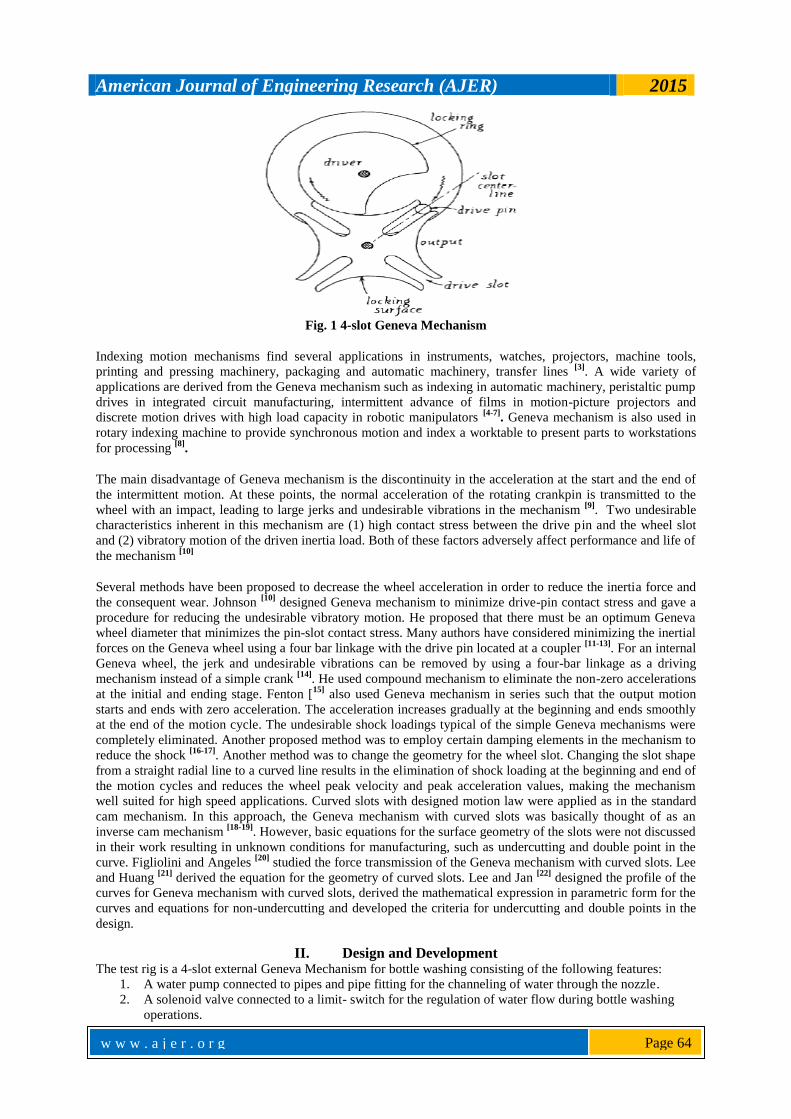
I. Introduction Geneva mechanism is a simple and widely used timing mechanism that provides intermittent motion
from a continuously rotating input. It consists of a rotating drive wheel (Driver) with a pin that reaches into a
slot of the driven wheel (Geneva wheel) advancing it by one step.
They are cheaper than cams, have good motion curve characteristics compared to ratchets and maintain good
control of its load at all times. In addition, if properly sized to the load, the mechanism generally exhibits very
long life. It is used in machine tools to index spindle carriers weighing several tonnes, in transfer machines for
indexing work piece from one work station to another, as a turret indexing mechanism in automatic lathe, in
counting instruments, peristaltic pump drives in integrated circuit manufacturing, intermittent advance of films
in motion-picture projectors and discrete motion drives with high load capacity in robotic manipulators.
One of the most important processes in beverage production is bottle washing. The high quality of the product
depends largely on how thoroughly the bottles are cleaned immediately before filling.
Manual washing of bottles does not give the desired productivity requirement of industrial setting. On this note,
a mechanized system of washing and detoxification is very imperative in order to achieve the desired
productivity for industries.
The need to address this problem has led to the design of a mechanized bottle washing and detoxification system
using a rotary table propelled by a Geneva mechanism [1]
Krishnakumar et al [2]
, designed and developed a Geneva mechanism for Film Frame. In their design, a 4-slot
mechanism was used in which a driver, (A), rotates at uniform angular velocity and for every revolution of the
driver, the Geneva wheel makes a fraction part of the revolution which is a function of the number of slots
(fig.1).
American Journal of Engineering Research (AJER) 2015
w w w . a j e r . o r g
Page 64
Fig. 1 4-slot Geneva Mechanism
Indexing motion mechanisms find several applications in instruments, watches, projectors, machine tools,
printing and pressing machinery, packaging and automatic machinery, transfer lines [3]
. A wide variety of
applications are derived from the Geneva mechanism such as indexing in automatic machinery, peristaltic pump
drives in integrated circuit manufacturing, intermittent advance of films in motion-picture projectors and
discrete motion drives with high load capacity in robotic manipulators [4-7]
. Geneva mechanism is also used in
rotary indexing machine to provide synchronous motion and index a worktable to present parts to workstations
for processing [8]
.
The main disadvantage of Geneva mechanism is the discontinuity in the acceleration at the start and the end of
the intermittent motion. At these points, the normal acceleration of the rotating crankpin is transmitted to the
wheel with an impact, leading to large jerks and undesirable vibrations in the mechanism [9]
. Two undesirable
characteristics inherent in this mechanism are (1) high contact stress between the drive pin and the wheel slot
and (2) vibratory motion of the driven inertia load. Both of these factors adversely affect performance and life of
the mechanism [10]
Several methods have been proposed to decrease the wheel acceleration in order to reduce the inertia force and
the consequent wear. Johnson [10]
designed Geneva mechanism to minimize drive-pin contact stress and gave a
procedure for reducing the undesirable vibratory motion. He proposed that there must be an optimum Geneva
wheel diameter that minimizes the pin-slot contact stress. Many authors have considered minimizing the inertial
forces on the Geneva wheel using a four bar linkage with the drive pin located at a coupler [11-13]
. For an internal
Geneva wheel, the jerk and undesirable vibrations can be removed by using a four-bar linkage as a driving
mechanism instead of a simple crank [14]
. He used compound mechanism to eliminate the non-zero accelerations
at the initial and ending stage. Fenton [15]
also used Geneva mechanism in series such that the output motion
starts and ends with zero acceleration. The acceleration increases gradually at the beginning and ends smoothly
at the end of the motion cycle. The undesirable shock loadings typical of the simple Geneva mechanisms were
completely eliminated. Another proposed method was to employ certain damping elements in the mechanism to
reduce the shock [16-17]
. Another method was to change the geometry for the wheel slot. Changing the slot shape
from a straight radial line to a curved line results in the elimination of shock loading at the beginning and end of
the motion cycles and reduces the wheel peak velocity and peak acceleration values, making the mechanism
well suited for high speed applications. Curved slots with designed motion law were applied as in the standard
cam mechanism. In this approach, the Geneva mechanism with curved slots was basically thought of as an
inverse cam mechanism [18-19]
. However, basic equations for the surface geometry of the slots were not discussed
in their work resulting in unknown conditions for manufacturing, such as undercutting and double point in the
curve. Figliolini and Angeles [20]
studied the force transmission of the Geneva mechanism with curved slots. Lee
and Huang [21]
derived the equation for the geometry of curved slots. Lee and Jan [22]
designed the profile of the
curves for Geneva mechanism with curved slots, derived the mathematical expression in parametric form for the
curves and equations for non-undercutting and developed the criteria for undercutting and double points in the
design.
II. Design and Development The test rig is a 4-slot external Geneva Mechanism for bottle washing consisting of the following features:
1. A water pump connected to pipes and pipe fitting for the channeling of water through the nozzle.
2. A solenoid valve connected to a limit- switch for the regulation of water flow during bottle washing
operations.

American Journal of Engineering Research (AJER) 2015
w w w . a j e r . o r g
Page 65
3. A Geneva mechanism mounted on a Geneva wheel shaft for intermittent positioning of bottles at the
washing station
4. A control panel housing the electrical circuit components of the test rig.
5. Bottle holders that grip the bottles at the neck.
6. An electric motor that provides the rotational motion transmitted to the shafts.
Fig. 2 Design of Geneva Mechanism
Fig. 3 Test Rig Assembly
The design is initiated by specifying the Crank (driver) radius, the roller diameter and the number of slots
(fig.2), as follows:
The Crank (Driver) radius, r2 = 60mm
The roller (pin) diameter = 12mm
The number of slots, n = 4 slots
The angle is half the angle subtended by adjacent slots, that is;
(1)
Where is the number of slots in the Geneva wheel.
American Journal of Engineering Research (AJER) 2015
w w w . a j e r . o r g
Page 66
(2)
Where is the center distance between the driver shaft and Geneva wheel shaft.
Using Pythagoras theorem,
Where is the radius of Geneva wheel
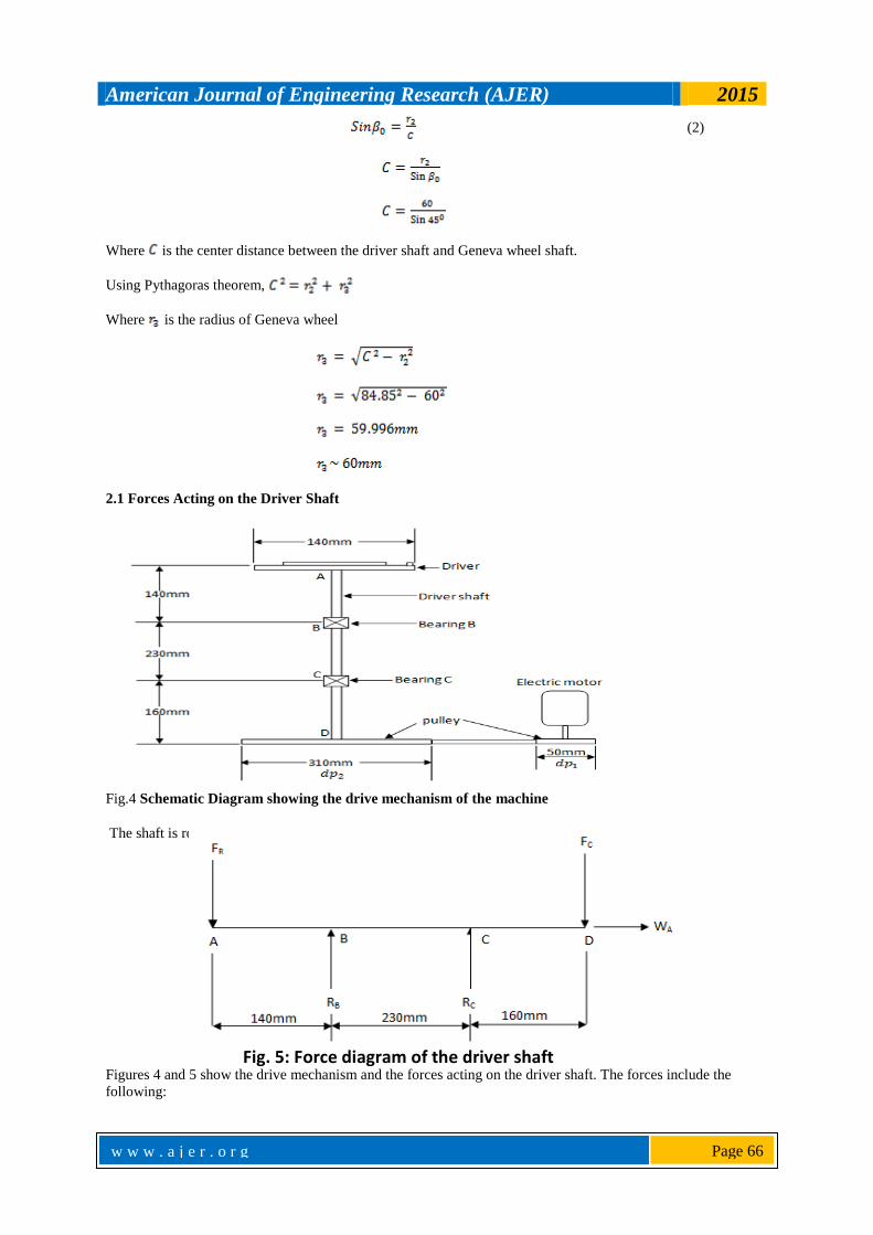
2.1 Forces Acting on the Driver Shaft
Fig.4 Schematic Diagram showing the drive mechanism of the machine
The shaft is rotated through 900 to a horizontal position as shown (fig. 5).
Figures 4 and 5 show the drive mechanism and the forces acting on the driver shaft. The forces include the
following:
Fig. 5: Force diagram of the driver shaft

American Journal of Engineering Research (AJER) 2015
w w w . a j e r . o r g
Page 67
Centrifugal force Fc of drive belt on driven pulley
Bearing reaction RB at point B.
Bearing reaction Rc at point C
Radial load FR at shaft end A due to inertia load of Driver
Axial Load WA due to weight of pulley, shaft and Driver.
Computation of these forces enables the presentation of a graphic representation of shaft loading from which
shear force and bending moment diagrams were obtained. Reaction forces RA, RB and axial load WA are needed
for the specification of bearings while the maximum bending moment on the shaft is an important requirement
for shaft diameter computation. Linear dimensions of the shaft in fig.4 and 5 were estimated based on the
anticipated length of immersion of the shaft in the chamber lower cover and space requirement for the bearings
and driven pulley.
2.2 Length of belt connecting the motor pulley and driven pulley
Length of the belt, is obtained using:[23]
(3)
Diameter of motor pulley, = 50mm
Diameter of driven pulley, =117.5mm
Center distance between motor and driven pulley, = 435mm
Substituting into the above equation, we have
2.3 Centrifugal force on the Driven pulley
Centrifugal force Fc acting on the driven pulley attached to the driver shaft is given by: [24]
But linear velocity,
Where = mass of the belt,
= angular velocity of driven pulley,
= radius of driven pulley
Since Density , mass of the belt can be computed using the equation:
American Journal of Engineering Research (AJER) 2015
w w w . a j e r . o r g
Page 68
Where = Density of belt material,
= Volume of belt material,
= Cross- sectional area of the belt,
= length of the belt
Mass of the belt,
For a selected Driver speed,
= 12.566 rad/s.
Electric motor speed, = 47rpm
The Centrifugal force, Fc becomes
2.4 Radial load FR at upper shaft end
The Radial load at the shaft end due to the Driver and Geneva wheel can be expressed as:
(4)
Where = mass of driver, = mass of Geneva wheel,
= radius of driven Driver, = radius of Geneva wheel,
= angular velocity of driver shaft,
American Journal of Engineering Research (AJER) 2015
w w w . a j e r . o r g
Page 69
Mass of Driver and locking ring (cam), = 1502g, mass of Geneva wheel, = 454g ( measured
with Tripple Beam balance, capacity: 2610g
Using a factor of safety of 12. This is the designated value for steel under shock load which is similar to the
shock load of the Geneva mechanism.
2.5 Reaction loads and
Considering the force diagram, for equilibrium of forces,
Taking moment about B,
Thus,
2.6 Maximum bending moment (BMmax)
Referring to fig.5, Bending moments are:
At A, BM1 = 0
At B, BM2 = 250.84(0.14) = 35.1176Nm
At C, BM3 = 250.84(0.14 + 0.23) – 403.415(0.23) = 0.02535Nm
American Journal of Engineering Research (AJER) 2015
w w w . a j e r . o r g
Page 70
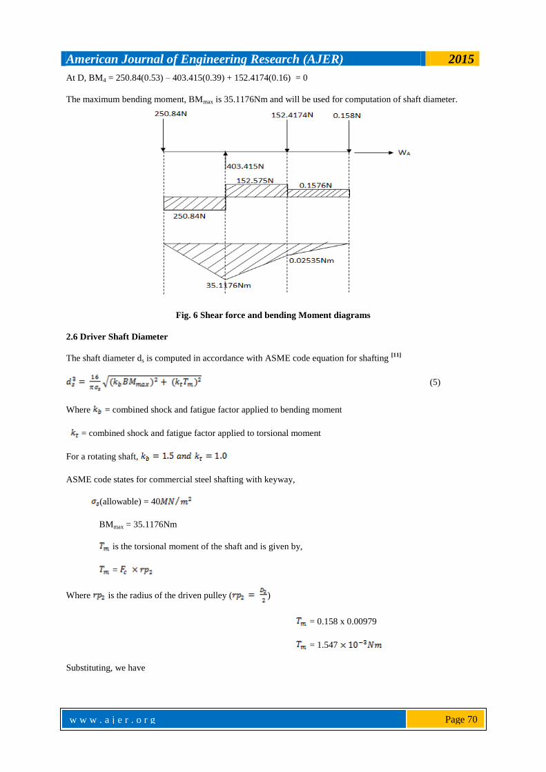
At D, BM4 = 250.84(0.53) – 403.415(0.39) + 152.4174(0.16) = 0
The maximum bending moment, BMmax is 35.1176Nm and will be used for computation of shaft diameter.
Fig.3.4 Shear force and Bending moment diagram
Fig. 6 Shear force and bending Moment diagrams
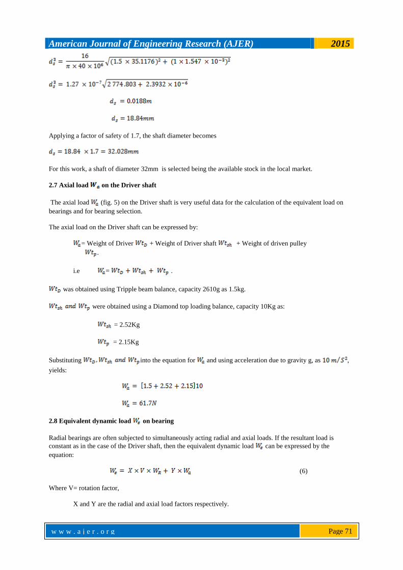
2.6 Driver Shaft Diameter
The shaft diameter ds is computed in accordance with ASME code equation for shafting [11]
(5)
Where = combined shock and fatigue factor applied to bending moment
= combined shock and fatigue factor applied to torsional moment
For a rotating shaft,
ASME code states for commercial steel shafting with keyway,
(allowable) = 40
BMmax = 35.1176Nm
is the torsional moment of the shaft and is given by,
=
Where is the radius of the driven pulley ( )
= 0.158 x 0.00979
= 1.547
Substituting, we have
American Journal of Engineering Research (AJER) 2015
w w w . a j e r . o r g
Page 71
Applying a factor of safety of 1.7, the shaft diameter becomes
For this work, a shaft of diameter 32mm is selected being the available stock in the local market.
2.7 Axial load on the Driver shaft
The axial load (fig. 5) on the Driver shaft is very useful data for the calculation of the equivalent load on
bearings and for bearing selection.
The axial load on the Driver shaft can be expressed by:
= Weight of Driver + Weight of Driver shaft + Weight of driven pulley
.
i.e = .
was obtained using Tripple beam balance, capacity 2610g as 1.5kg.
were obtained using a Diamond top loading balance, capacity 10Kg as:
= 2.52Kg
= 2.15Kg
Substituting into the equation for and using acceleration due to gravity g, as ,
yields:
2.8 Equivalent dynamic load on bearing
Radial bearings are often subjected to simultaneously acting radial and axial loads. If the resultant load is
constant as in the case of the Driver shaft, then the equivalent dynamic load can be expressed by the
equation:
(6)
Where V= rotation factor,
X and Y are the radial and axial load factors respectively.
American Journal of Engineering Research (AJER) 2015
w w w . a j e r . o r g
Page 72
For deep groove ball bearings, [24]
is the radial load . The higher of the two values that is
is taken for the purpose of bearing safety and uniformity. Thus taking and
substituting the values of in the above equation results in:
2.9 Bearing load capacity
The relationship between the rating life , the equivalent dynamic load and the bearing load capacity is
represented by: [24]
(7)
is a constant with value equal to 3 for ball bearings, and
.
The bearing load capacity is thus calculated as:
III. Conclusions The test rig uses Geneva mechanism to index a table intermittently for bottle washing. The test rig was
designed, constructed, assembled and used to run the experimental study. As the drive speed of the Geneva
mechanism increases, the cycle time, washing time and indexing time decreases while the maximum pin-slot
contact force and washing efficiency increases. The washing efficiency of the test rig from 5rpm to 19 rpm
increased from 81.57% to 96.89%. It is concluded that at 19rpm, the designed bottle washing machine had
washing time of 2.434 seconds and maximum efficiency of 96.89%.
References
[1] Ejeogo Gerald (2014) “Development and Analysis of Geneva Mechanism for Bottle Washing" M.Eng Thesis, department of
mechanical & Production Engineering, Enugu State University of Science & Technology, Enugu, Nigeria. [2] Krishnakumar M., Prabakaran A., Sudhakar K., Senthilkumar R., (2011) “Design and
Fabrication of Film frame by Geneva Mechanism”, Thanthai Periyar Goverment Institute of Technology, Vellore
[3] Figliolini G., Rea P., Angeles J., (2007) ”Synthesis of Geneva Mechnaism and their equivalent Pure-Rolling Cams”, 12th IFToMM World Congress, Besancon France
[4] Beltz R. K and Hurst J. C., (1975) “Peristaltic pump metering and dispensing system”. Technical Digest – Western Electric
Company,USA, No. 37 3-4. [5] Egorov OD. Nadezhdin IV, (1988) “Use of Geneva Mechanisms in Industrial Robots”, Soviet Engineering Research, vol.8,
no.11,USA 134-137.
[6] Meyer G., (1988) “A tested method for precise Intermittent Motion”, Machine Design vol. 60, no.1, 140-143. [7] Pazouki M.E., Jones J.R., (1982) “The kinematic synthesis of a linkage driven Geneva Mechanism”, Mechanism and
Machine theory, 17(3), 221-228.
[8] Groover P. Mikell, (2009) “Automation, Production Systems and Computer integrated Manufacturing”, Third Edition, Pearson Education 467-471.
American Journal of Engineering Research (AJER) 2015
w w w . a j e r . o r g
Page 73
[9] Sujan V. A. and Meggiolaro M. A., (2000) “Dynamic Optimization of Geneva Mechanism”, International Conference on Gearing, Transmissions and Mechanical Systems, Daizhong Su, Professional Engineering Publishing, London 687-696
[10] Johnson R. C., (1956) “How to Design Geneva Mechanisms to Minimize Contact Stresses and Torsional Vibrations”,
Machine Design 28, N0.6, 107-111. [11] Hall Allens JR., Holowenko Alfred M. S. and Laughlin Herman G., (2009). “Schaum’s Outline Series of Theory and
Problems of Machine Design”, Tata McGraw- Hill Edition.
[12] Shigley J.E. and Uicker J.J, JR., (1995) “Theory of Machines and Mechanisms”, Second Edition, Singapore: McGraw-Hill, Inc. 372-376.
[13] Tao, D.C., Krisnamoorthy S. (1978) “Mechanism and Machine Theory”, 13, 585-591.
[14] Dijksman E.A., (1966) , “Jerk-free Geneva wheel driving”, Journal of Mechanisms 1 235-283. [15] Fenton E.A., (1975) “Geneva Mechanisms connected in series”, ASME Journal of Engineering for Industry 97, 603-608.
[16] 16. Sadek, E. A, Lioyd J. L, Smith M.R., (1990) “A new design of Geneva drive to reduce shock
loading”,Mechanism and Machine Theory 25, 589-595. [17] Cheng C.Y., Lin Y., (1995) “Improving dynamic performance of the Geneva mechanism using non-linear spring
elements”, Mechanism and Machine Theory 30, 119-129.
[18] Fenton R.G., Zhang Y., Xu J., (1991) “Development of a new Geneva mechanism with improved kinematic characteristics”, ASME Journal of Mechanical Design 113, 40-45.
[19] Lee H.P., (1998) “Design of a Geneva mechanism with curved slots using parametric polynomials”, Mechanism and
Machine Theory 33 (3), 321-329.
[20] Figliolini G., Rea P., Angeles J., (2007) “Synthesis of Geneva Mechnaism and their equivalent Pure-Rolling Cams”, 12th
IFToMM World Congress, Besancon France.
[21] Lee H.P., (1998) “Design of a Geneva mechanism with curved slots using parametric polynomials”, Mechanism and Machine Theory 33 (3), 321-329.
[22] Lee Jyh-Jone, Jan Bin-Heng, (2008). “Design of Geneva mechanism with curved slots for non-undercutting
manufacturing”, Mechanism and Machine Theory. [23] Khurmi R. S. and Gupta J. K, (2004) “A textbook of Machine Design”, S. Chand and Company Ltd, New Delhi,
[24] Khurmi R. S. and Gupta J. K., (2005) “Theory of Machines”, S. Chand and Company Ltd, New Delhi,.
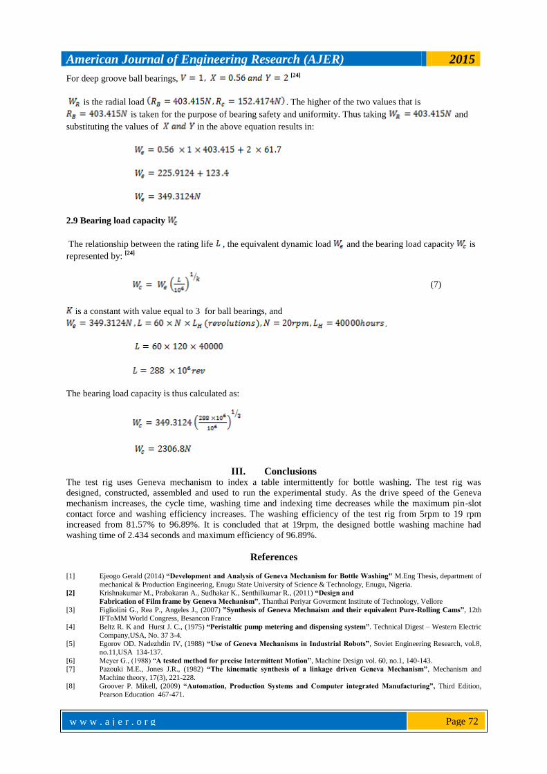
Fig.7 Rig Assembly
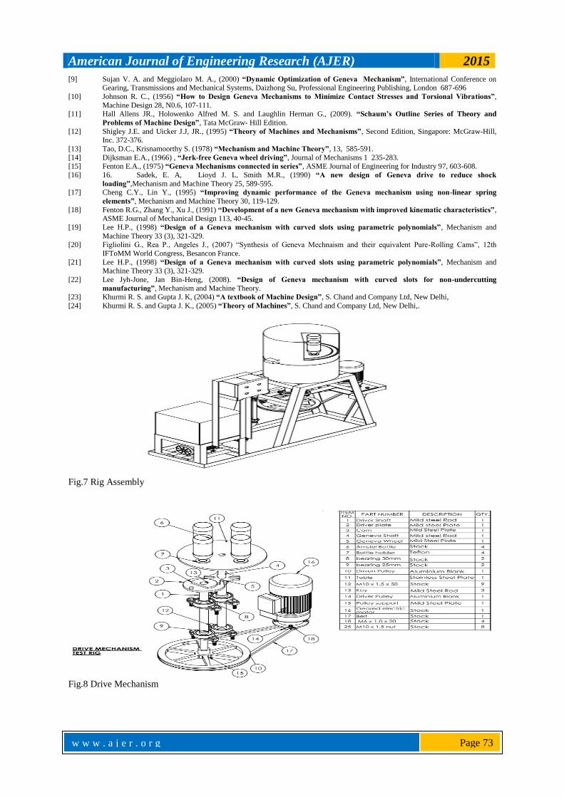
Fig.8 Drive Mechanism