Development and application of dynamic secondary cooling...
6
MILLENNIUM STEEL 2012 77 Development and application of dynamic secondary cooling and soft reduction for slab casting Dynamic secondary cooling and soft reduction control models have been developed for a newly commissioned slab caster to improve the quality of the cast slab. The system comprises three parts: dynamic thermal tracking model, dynamic spray water optimisation model and a dynamic soft reduction control model. The system has been shown to be stable and robust for the production of ship plate grades and, following further calibration, will be applied to the whole product mix. C hina’s steel producers are facing a series of severe challenges from users who require higher quality steels. In continuous casting, internal cracks, centre segregation and centre porosity are usually the main bottlenecks preventing development of high-strength steel grades with qualified mechanical properties. For this reason, dynamic secondary cooling and soft reduction technology have been two of the key technologies adopted by many steel plants throughout the world in the past few years to improve slab quality. In casting, the interdendritic liquid steel in the mushy zone of the final solidification stage flows to the centre area through convection and bulging. This leads to centreline segregation. The volume contraction of steel on solidification can also lead to central porosity where there is poor feeding or compensation. Also, the cyclical cooling and reheating of the strand surface temperature during casting is connected with the formation of broad face cracking, subsurface cracking and other defects. The appearance and intensity of centre segregation and centre porosity or other defects are closely related to steel grade, liquid steel superheat, casting speed and cooling history. Dynamic soft reduction, combined with dynamic secondary cooling, has been shown to be an effective way to minimise centre segregation and porosity. In this paper, a newly developed thermal tracking, dynamic secondary cooling and dynamic soft reduction system for slab casting control is described. DYNAMIC THERMAL TRACKING MODEL Accurate and timely access to the solidification temperatures of the slab being cast are the basic requirements for the implementation of dynamic secondary cooling and soft reduction. A model for the determination of the temperature field of the continuously cast slab was made for the casting practices adopted in production and based on the basic Authors: Yunhe Chang, Ke Liu, Zhanguang Han and Jiaquan Zhang State Key Laboratory of Advanced Metallurgy and University of Science and Technology, Beijing CASTING a r Fig 1 Structure of dynamic thermal tracking model
Transcript of Development and application of dynamic secondary cooling...
MIL
LEN
NIU
M S
TEEL
201
2
77
Development and application of dynamic secondary cooling and soft reduction for slab castingDynamic secondary cooling and soft reduction control models have been developed for a newly commissioned slab caster to improve the quality of the cast slab. The system comprises three parts: dynamic thermal tracking model, dynamic spray water optimisation model and a dynamic soft reduction control model. The system has been shown to be stable and robust for the production of ship plate grades and, following further calibration, will be applied to the whole product mix.
China’s steel producers are facing a series of severe challenges from users who require higher quality
steels. In continuous casting, internal cracks, centre segregation and centre porosity are usually the main bottlenecks preventing development of high-strength steel grades with qualified mechanical properties. For this reason, dynamic secondary cooling and soft reduction technology have been two of the key technologies adopted by many steel plants throughout the world in the past few years to improve slab quality.
In casting, the interdendritic liquid steel in the mushy zone of the final solidification stage flows to the centre area through convection and bulging. This leads to centreline segregation. The volume contraction of steel on solidification can also lead to central porosity where there is poor feeding or compensation. Also, the cyclical cooling and reheating of the strand surface temperature during casting is connected with the formation of broad face cracking, subsurface cracking and other defects. The appearance and intensity of centre segregation and centre porosity or other defects are closely related to steel grade, liquid steel superheat, casting speed and cooling history.
Dynamic soft reduction, combined with dynamic secondary cooling, has been shown to be an effective way to minimise centre segregation and porosity. In this paper, a newly developed thermal tracking, dynamic secondary cooling and dynamic soft reduction system for slab casting control is described.
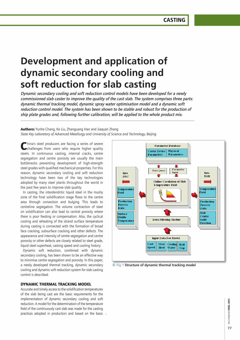
DYNAMIC THERMAL TRACKING MODELAccurate and timely access to the solidification temperatures of the slab being cast are the basic requirements for the implementation of dynamic secondary cooling and soft reduction. A model for the determination of the temperature field of the continuously cast slab was made for the casting practices adopted in production and based on the basic
Authors: Yunhe Chang, Ke Liu, Zhanguang Han and Jiaquan ZhangState Key Laboratory of Advanced Metallurgy and University of Science and Technology, Beijing
CASTING
a
r Fig 1 Structure of dynamic thermal tracking model

MIL
LEN
NIU
M S
TEEL
201
2
78
different temperatures, are considered to be isotropic partitioned constants for liquid, mushy and solid states, respectively
` From the meniscus to the secondary cooling zone, symmetrical cooling is assumed for the loose and fixed sides of the slab
` Effective heat transfer co-efficients are used for the overall description of heat transfer of slab surface in the secondary cooling zones, which include the contribution from heat radiation, heat conduction through backup rolls and heat convection during water spraying.
Based on these assumptions the control equation for the heat transfer and solidification process can be simplified as:
(1)Where,Ceff is equivalent heat capacity, J/(kg·°C)k is thermal conductivity, W/(m.°C)t is time, sT is temperature, °Cρ is density, kg/m3
Initial condition:Temperature distribution is assumed to be even at the meniscus and equal to the pouring temperature of the molten steel, Tc.
(2)Boundary conditions:Centre of the slab domain:
(3)Surface of the slab domain:
Mould region:
(4)Secondary cooling zones:
(5)Air cooling zone:
(6)
theory of solidification and heat transfer (see Figure 1). The model uses real-time temperature and solidification information from the mould meniscus to the end of the control region, and calculates periodically based on the transient casting conditions or technology parameters read from the Level 1 control system.
In the model, the strand – from mould meniscus to the end of control region – is divided into 426 slices (see Figure 2). Each 100mm slice is an information storage unit generating time-related data from the meniscus, present location and grid temperatures from the centre to the upper slab surface (ie, loose side of the slab strand). Data are stored from the start of casting production and updated periodically.
Cartesian co-ordinates were adopted for each computational slice, in which the X, Y and Z axes represent width, thickness and casting directions, respectively. Based on the characteristics of the continuous casting process, the basic assumptions used in the establishment of the heat transfer model of solidification are given as follows:` Compared with the casting speed, longitudinal heat
transfer along with casting direction can be neglected` The temperature gradient along the width direction of
the slice domain is not dominant so heat transfer in that direction can be ignored
` Heat transfer of the slab is treated as a heat conduction process in which possible effects on the heat transfer from the contribution of fluid flow, both in the mushy zone and in the bulky liquid region, are dealt with through effective thermal conductivities according to the solidifying state
` The thermal physical properties of steel, such as heat capacity, thermal conductivity and density at
r Fig 2 Schematic of slice generation and computational domain

CASTING
MIL
LEN
NIU
M S
TEEL
201
2
79
a
Where: φ is heat flux,KJ/m2: A, B are experimental constants; h is the heat transfer coefficient in kW/m2•°C; Ts, Tw and To are temperatures of slab surface, cooling water and ambient in °C; σ is the Stefan-Boltzmann constant and assumed to be 5.67×10⁻⁸ W/(m2·K4); ε is the radiation coefficient of slab surface (black degrees), and is 0.8 in the model.
Equations 1 to 6 constitute a one-dimensional unsteady mathematical model of the computational slice for the description of heat transfer and solidification during casting. The finite difference method is used to solve the differential equations of heat transfer.
In the actual production process, the slices at different times have different information for different locations, which includes the contribution of the variable process conditions, such as casting speed, tundish temperature, cooling intensity of each cooling zone and steel grade. The information, temperature field and location of slices, is dynamically tracked in the model.
Thus a non-steady solidification heat transfer model is established for each slice, which is discretised and solved through the finite difference method. Accordingly, the model can describe the temperature field of each slice at different times and in different locations. The updated temperature of each slice represents the local temperature field of the strand, and the collection of process parameters and calculation for the temperature field of the slices are updated every 5 seconds. Thus, the real-time temperature distribution of the strand can be revealed through the information integration of all slices.
DYNAMIC SECONDARY COOLING MODELThe database module of the secondary cooling model is responsible for providing the initial, maximum and minimum amount of secondary cooling water, its allocation and other process parameters corresponding to the casting speed for the online calculation module. This is the core of the model, which receives the slice information (time, location and temperature field) provided by the thermal tracking model, calculates the effective casting speed of each cooling area for slab continuous casting and combines with the parameters of the database to determine the water flow rate of each zone. Spray water allocation is determined via water meter databases related to the given target surface temperatures in every cooling zone, effective casting speed and the method of target surface temperature control. Thus, the surface temperatures of the slab are controlled online to optimise the temperature field with the given target surface temperatures and to minimise reheating (see Figure 3).
In addition, the system can support users to add new steel grades and modify the original water spray table if necessary. The control system has various protective
measures, such as limitation to maximum or minimum water flow rate.
Based on the mechanical properties of steels at elevated temperatures, the surface target temperatures for the slab in the secondary cooling zones are determined for any given steel grade in the product mix, in which related metallurgical criteria are considered for control of thermal stress on the surface of slabs. Offline simulation and calculation for cooling optimisation are carried out in advance by secondary cooling software to get the best relationship between casting speed and the related secondary cooling water allocation. The water flowrates obtained under different casting speeds are stored in the database as the basic table for the water sprays.
To avoid an over response of water sprays to any fluctuation of casting speed, we define the concept of effective casting speed in the control model, as given in equation 7.
(7)
Where, vi is the actual casting speed; v
eff is the effective
casting speed; vc is average casting speed and k
i is a constant
factor for each given cooling zone. Thus, the model can ensure a slower variation of the surface temperatures with increments in casting speed, and the frequently observed dramatic changes of surface temperatures under a normal control system are avoided during the change of casting speed, which should be beneficial to steel surface quality.
Finally, the amount of water is optimised by a target
r Fig 3 Structure of dynamic secondary cooling model
MIL
LEN
NIU
M S
TEEL
201
2
80
surface temperature control method based on the temperature field from the dynamic thermal tracking model using equation 8.
,(8),
Where, ∆Qi is regulation amount of water, m3/min; K1 and K2 are adjustment co-efficients determined by experience and in-situ production; ∆Ti and ∆Ti-1 are the deviation of the temperature at i and i-1 times. The amount of water regulation is increased or decreased accordingly through the evaluation on ∆Ti and the difference between ∆Ti and ∆Ti-1. The surface temperatures should approach the target temperatures at given set points as quickly as possible along with the water regulation.
The dynamic secondary cooling control model based on the strand surface temperature reheating feedback is described in equation 9.
(9),
Where ∆Ti is the difference of surface temperature reheating in °C/m; Ti and Ti-1 are surface temperature reheating values of import and export for I cooling zone in °C/m; Taim is target value of surface temperature reheating, 0≤Taim≤100 in °C/m;
If Ti,T
aim or T
i-1,T
aim, following the proportional integral
derivative (PID) principle:
(10),
Where, ∆Qk is regulation amount of water in m3/min,
less than 10% of Qk; K is the sample number; ∆T
k ,
∆Tk-1
are k and k-1 sample difference of surface temperature reheating; K
p , K
i , K
d are the proportional co-
efficient, integral co-efficient and differential co-efficient, respectively.
DYNAMIC SOFT REDUCTION MODELDue to volume contraction during solidification, a shrinkage cavity and/or porosity can be produced at the crater of the final solidification region, and centreline segregation can be produced due to solute redistribution during solidification and fluid flow induced by thermal convection or bulging. For these reasons, a dynamic soft reduction control model has been developed to compensate for solidification shrinkage by decreasing the roll gaps in the region of the centreline mushy zone. Dynamic soft reduction can minimise the formation of internal voids
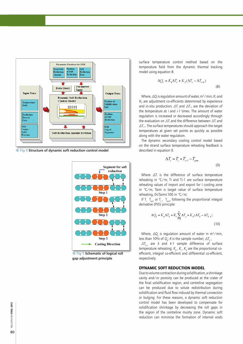
r Fig 5 Schematic of logical roll gap adjustment principle
r Fig 4 Structure of dynamic soft reduction control model

CASTING
MIL
LEN
NIU
M S
TEEL
201
2
81
a
the dynamic thermal tracking model, the location of the centreline mushy zone is determined by the online roll gap calculation module based on the centreline solid fraction.
Combined with the preset parameters for the position of soft reduction provided by the database module, the online calculation module calculates the range of soft reduction and determines the initial segment and end segment for soft reduction implementation. The reduction needed is then allocated to the assigned segments. The initial soft reduction can be further modified or optimised to follow the maximum soft reduction rate given by the modification module. Finally, the roll gaps of segments are set up based on the basic roll gap, and distributed to the PLC control system.
The dynamic soft reduction control system allows users to add new steel grades and modify appropriate process parameters. The system is designed with a function to optimise the roll gap process and the maximum/minimum soft reduction allowed in order to protect the equipment and enhance accurate control and equipment life by avoiding frequent movement of the segment hydraulic cylinders. Upper and lower threshold values are also used in the control model.
As shown in Figure 5, the overall roll gaps of the strand will be adjusted in a controlled way; ie, when the roll gaps of segments for soft reduction begin to change, the roll gap of the following segments changes upon its arrival at the next roller. The gap adjustments of the following segments take place step by step based on the casting speed, which improves the effectiveness of the soft reduction and avoids the excessive deformation resistance from the following solidified slab.
and prevent the interdendritic fluid flow of the condensed liquid steel, especially in the transverse direction.
Additionally, the compression produced by the soft reduction can also promote liquid steel flow in the reverse direction of casting, which can lead to the redistribution of solute elements in the liquid steel. Thus the solidified slab structure is usually more uniform and compact under soft reduction, with less centreline segregation and porosity.
The key technologies of dynamic soft reduction are to use the dynamic soft reduction control model accurately to predict the location of the centreline mushy zone, and to determine the position of soft reduction and the soft reduction required, giving consideration to the characteristics of different steels.
As shown in Figure 4, the dynamic soft reduction control model comprises the database module of parameters, online roll gap calculation module and soft reduction modification module.
The maximum soft reductions for different steel grades are shown in Table 1.
To avoid soft reduction in the crack-sensitive zone near the very end of the crater, we take the region of f
s =
0.3-0.7 as the operational zone for soft reduction (where fs
is centreline solids fraction). This is an acceptable range to compensate for solidification shrinkage without inducing any possible internal cracks.
The total amount of soft reduction is allocated linearly between the soft reduction segments based on the evaluation of the centreline solids fraction of the slab casting according to equation 11.
(11)
Where, Ri is the soft reduction of segment; R
Max is the
maximum soft reduction; fs,i is the centreline solids fraction
of the segment; fs,min
= 0.3, fs,max
= 0.7.The total soft reduction, position of soft reduction, soft
reduction rate and basic roll gaps of different kinds of steels are provided by the database module. Upon receiving the real-time solidification temperature field provided by
Steel grade Maximum soft reduction, mmLow carbon 2.3 Peritectic 3.2 Medium carbon 3.5 High carbon 4.5
r Fig 6 A running interface of control system
r Table 1 Maximum soft reduction for different steel grades
MIL
LEN
NIU
M S
TEEL
201
2
82
CASTING
APPLICATIONThe overall dynamic control models have been developed and integrated in a domestic caster. The main casting steel grades produced are ship plate, automobile, structural, container and bridge steels. The two strand caster has 19 segments per strand with 20 spray zones and 41 control loops. The main technical parameters are shown in Table 2.
The online control models have been programmed with the basic parameters of the caster using Visual C++ 6.0 and Windows-type user friendly interfaces, as shown in Figure 6. The basic parameters for the continuous casting process, temperature history and solidified shell of the slab strand in casting direction are described through a combination of data, tables and figures.
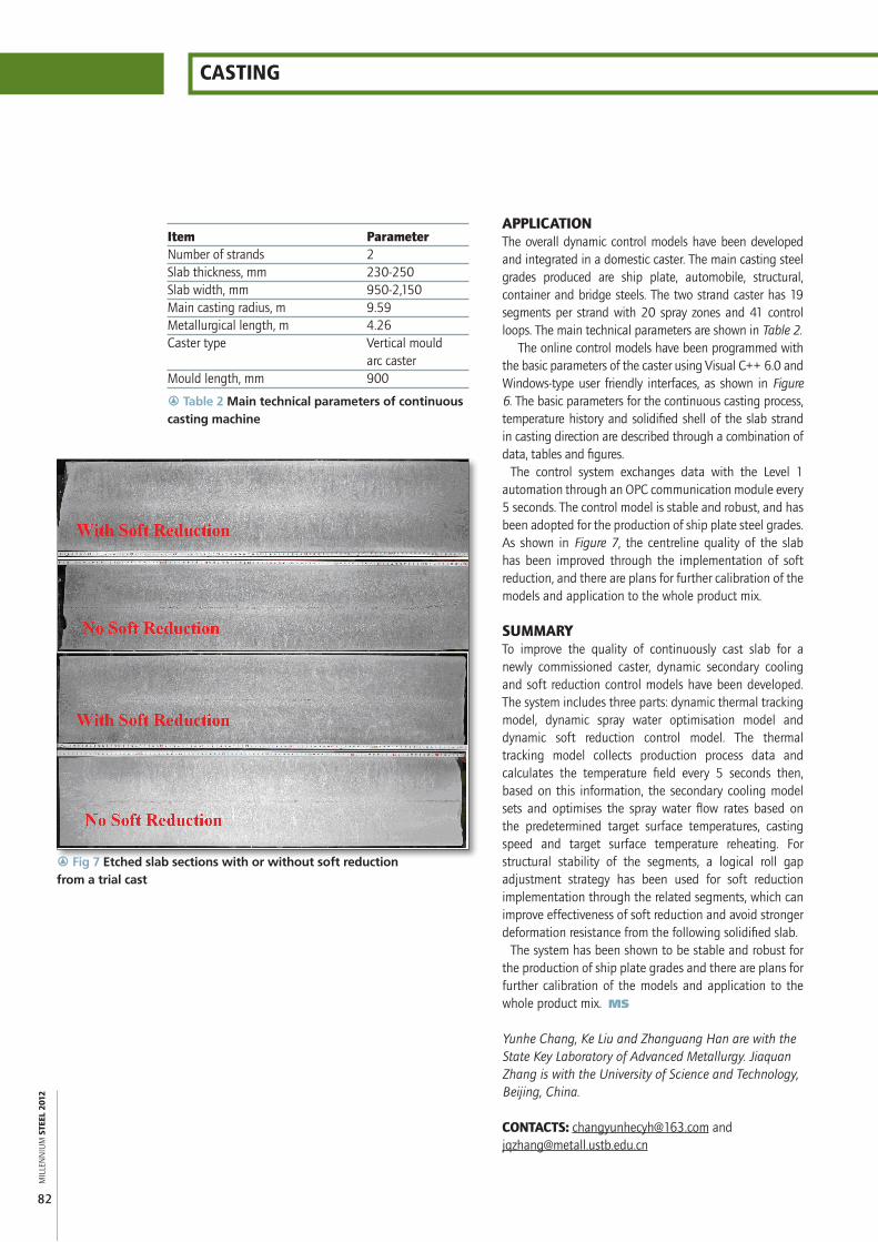
The control system exchanges data with the Level 1 automation through an OPC communication module every 5 seconds. The control model is stable and robust, and has been adopted for the production of ship plate steel grades. As shown in Figure 7, the centreline quality of the slab has been improved through the implementation of soft reduction, and there are plans for further calibration of the models and application to the whole product mix.
SUMMARYTo improve the quality of continuously cast slab for a newly commissioned caster, dynamic secondary cooling and soft reduction control models have been developed. The system includes three parts: dynamic thermal tracking model, dynamic spray water optimisation model and dynamic soft reduction control model. The thermal tracking model collects production process data and calculates the temperature field every 5 seconds then, based on this information, the secondary cooling model sets and optimises the spray water flow rates based on the predetermined target surface temperatures, casting speed and target surface temperature reheating. For structural stability of the segments, a logical roll gap adjustment strategy has been used for soft reduction implementation through the related segments, which can improve effectiveness of soft reduction and avoid stronger deformation resistance from the following solidified slab.
The system has been shown to be stable and robust for the production of ship plate grades and there are plans for further calibration of the models and application to the whole product mix. MS
Yunhe Chang, Ke Liu and Zhanguang Han are with the State Key Laboratory of Advanced Metallurgy. Jiaquan Zhang is with the University of Science and Technology, Beijing, China.
CONTACTS: [email protected] and [email protected]
Item ParameterNumber of strands 2Slab thickness, mm 230-250Slab width, mm 950-2,150Main casting radius, m 9.59Metallurgical length, m 4.26Caster type Vertical mould arc casterMould length, mm 900
r Fig 7 Etched slab sections with or without soft reduction from a trial cast
r Table 2 Main technical parameters of continuous casting machine