Developing Laboratory Exercise in IEC 61850 Standard - Theseus
35
1 Wu Liang Developing Laboratory Exercise in IEC 61850 Standard Technology and Communication 2010
Transcript of Developing Laboratory Exercise in IEC 61850 Standard - Theseus

1
Wu Liang
Developing Laboratory Exercise in IEC
61850 Standard
Technology and Communication
2010

2
VAASAN AMMATTIKORKEAKOULU
UNIVERSITY OF APPLIED SCIENCES
Degree Programme of Information Technology
Abstract
Author Wu Liang
Title Developing Laboratory Exercise in IEC 61850 Standard Year 2010
Language English
Page 35
Name of Supervisor Smail Menani
The main objective of this thesis is to integrate the knowhow related to the
IEC61850 standard to the laboratory exercises of a data transmission course. This
is done through a careful design of the experimental set up, selection of tools and
devices and description of laboratory tasks and objectives.
The experimental setup provides step by step configuration of the devices to be
used in different tasks. Selection of tools is according to the configuration
required for a specific lab session, however, the detail of tools and devices are
described in this document. The description of laboratory tasks involves the work
to be done by the students during the laboratory hours. The entire laboratory
exercise is divided into three parts: Digital Input Implementation of VAMP Feeder
Manager, GOOSE message activated by an on/off event and GOOSE message
activated by threshold event.
In addition to the written instructions of the telecommunication laboratory
exercise for students and supervisor, the project provides detailed decoding
information of GOOSE messages and a specific instruction for reading before the
laboratory exercises.
This thesis principally describes the design, structure and implementation process
of the laboratory exercises using VAMP Feeder Manager 257. Reliability of
laboratory experiment is achieved through several tests.
Laboratory exercises documentation is not included in this document but
delivered separately to the concerned teacher to be used in his lab course.
Keywords IEC61850, GOOSE, VAMP Feeder Manager

3
Abbreviation
IED Intelligent Electrical Device
MMS Manufacturing Message Specification
IEC International Electro technical Committee
ACSI Abstract communication service interface
LN Logic Node
ANS.1 Abstract Syntax Notation One
DAType Data Attribute type
GCB GOOSE control block
GOOSE Generic object oriented substation event
GSE Generic substation event
GSSE Generic substation state event
LD Logical device
LLN0 Logical node zero
PDU Protocol data unit
RCB Report Control Block
DI Digital Input
U< Under-Voltage
VO Virtual Output

4
Table of Content
Abstract ................................................................................................................... 2
Abbreviation ............................................................................................................ 3
1. Introduction ...................................................................................................... 6
2. Equipments ....................................................................................................... 8
2.1. Vamp Feeder Manager 257 .................................................................... 8
2.2. VAMPSET Setting and Configuration tool ........................................... 8
2.3. IEC Simple Tester ................................................................................ 10
2.4. GOOSE Sender ..................................................................................... 11
2.5. Wireshark .............................................................................................. 11
3. Laboratory Implementation ............................................................................ 13
3.1. Configuration ....................................................................................... 13
3.2. Digital Input Implementation of VAMP Feeder Manager ................... 14
3.2.1. About this work ......................................................................... 14
3.2.2. Equipements .............................................................................. 15
3.2.3. Connections: .............................................................................. 15
3.2.4. Configuration and Result .......................................................... 15
3.3. GOOSE message activated by an on/off event .................................... 18
3.3.1. About this work ......................................................................... 18
3.3.2. Equipements .............................................................................. 18
3.3.3. Connections: .............................................................................. 18
3.3.4. Configuration and Result .......................................................... 19
3.4. GOOSE message activated by threshold event ................................... 25
3.4.1. About this work ......................................................................... 25
3.4.2. Equipements .............................................................................. 25
3.4.3. Connections: .............................................................................. 25
3.4.4. Configuration and Result .......................................................... 25
4. Conclusion ..................................................................................................... 34

5
5. References ...................................................................................................... 35

6
1. Introduction
With development of technical communication more and more reliable protocols
were published in order to prove the quality of telecommunication. But it is
difficult to integrate protocols into different IEDs manufactured by different
companies. They always use specific communication protocol of their own
manufacturer. Thus a protocol combines them and facilitates them the ability to
work in a same network to share information and commands that are needed. IEC
61850 standard was introduced to avoid interoperability problems (Detail for
IEC61850 is in Appendix). GOOSE is a kind of message applied for fast and
reliable service in IEC 61850. It is also the main topic in the laboratory exercise
you designed. This laboratory exercise is created for students of this institution.
The aim is to let them get familiar with IEC 61850 standard and GOOSE
messages i.e. how the protocol is used in real applications. The laboratory exercise
contains five important functions:
1. Settings and functions of VAMP Feeder Manager
2. Getting familiar with all the software to be used
3. RCB application
4. Analyzing the structure of GOOSE messages i.e. decoding GOOSE messages
5. GOOSE messages application in power protection control
According to the functions above, the entire laboratory work is divided into four
parts:
Exercise1: Digital Input Implementation
Exercise2: GOOSE message activated by an on/off event
Exercise3: GOOSE message activated by threshold event
Exercise4: GOOSE Decoding
In this thesis Exercise 1 to Exercise 3 are elaborated.
The structure of entire laboratory exercises is shown below:

7
Figure 1.1: Architecture of laboratory

8
2. Equipments
The list for hardware and software using in this laboratory work:
Hardware:
Vamp Feeder Manager 257
Computer
Function Generator
Software:
VAMPSET
IEC Simple Tester
GOOSE Sender
Wireshark
2.1. Vamp Feeder Manager 257
The protection relay of VAMP is used for selective protection of cable, electric
motor, capacitor, reactor and bus bars in substation, power plant and other
industrial manufactures. It has normal protection functions and some special ones
such as bay control, measurement and communication etc.
The main feature of Vamp Feeder Manager 257 can be found in *Ref 1.
2.2. VAMPSET Setting and Configuration tool
VAMPSET is management software for configuring VAMP relays. All the
parameters in VAMP relays can be represented by VAMPSET. Remote control of
VAMP relays by using VAMPSET make configurations easier and safer for people.
This software runs on Windows XP/98/95/2000/NT and Windows 7 environment.
It supports TCP/IP and IEC 61850 communication. The following picture is the
general interface of VAMPSET.

9
Figure 2.2.1: General Interface of VAMPSET
All functions and parameters of the relay can be found in the main menu which is
on the left side of software interface. Configuration command is located on the
above tool bar. For example there is a control panel in VAMPSET with which you
can remotely control the relay manager, the push buttons on the panel are exactly
the same as those on the machine.

10
Figure 2.2.2: Control panel in VAMPSET
In addition, you can change the common configuration through the options in the
main menu.
2.3. IEC Simple Tester
It is simple test software to monitor the LN, object and their attributes. It contains
some main functions, such as read values from the device and control switch
inside the relay. In addition to that, it has most important function that is RCB
(Report Control Block) and GOOSE detector. In some circumstances, VAMP
Feeder Manager will continuously send report to control system in order to make
sure there is no problem, RCB is a model for monitoring this kind of report.

11
Figure 2.3.1: A connected IEC Simple Tester
2.4. GOOSE Sender
This software is used for simulating GOOSE messages. By using this software
you can give a GOOSE command to VAMP Feeder Manager and if there is related
configuration in the relay there will be some response from the relay according to
the configurations made in GCB.
2.5. Wireshark
Wireshark is a packet analyzer which is used for network analysis. It is easy for
the user to see all traffic being transmitted over the network. Wireshark is
convenient for common users without worrying about license keys or fees. Since
the source code is freely available, new protocols are easily to be added to
Wireshark. For Wireshark functions, it can capture the protocols you want in a
large number of protocols or programs. The protocol decoders in Wireshark
always are updated. This is good for the users saving time on decoding some

12
unusual protocols. In a word, Wireshark is free and convenient software for
network analysis.

13
3. Laboratory Implementation
3.1. Configuration
Basically you use Ethernet to connect relay and PC. Use the Ethernet port for PC
and the relay manager with a RJ-45 cable. After the connections are done, run
Software VAMPSET on PC. To start with, set the IP address for the relay manager
to make connections. Set the IP address of the Relay Manager to 192.168.65.2 and
for the PC use IP address: 192.168.65.20
Use the following figure to use the keypad.
Figure 3.1.1: Keys on the keypad
1. Enter and confirmation key (ENTER)
2. Cancel key (CANCEL)
3. Up/Down [Increase/Decrease] arrow keys (UP/DOWN)
4. Keys for selecting submenus [selecting a digit in a numerical value]
(LEFT/RIGHT)
5. Additional information key (INFO)
To set IP of relay manager, scroll the down key to find the menu “Comm. options”.
In case of those options, select „Bus‟. (In figure 3.1.2)

14
Figure 3.1.2
Now click the Right arrow key a few times to reach Ethernet Port. Hit enter key to
enter in menu options. Here you need to enter password for configure the relay
manager and the password is 0002. The original state for password was 0000.
Use the down key select IP A. Observe this IP address, should be according to the
static range for IP address.
Figure 3.1.3: Setting static IP address for relay
3.2. Digital Input Implementation of VAMP Feeder Manager
3.2.1. About this work
The relay feeder managers are used to configure/command the relay devices
connected to a specified network. In addition to that, students will get themselves
familiar with different operating tools of VAMP relays using VAMPSET
andIEC61850 Simple Tester.

15
3.2.2. Equipments
Vamp relay 257
RJ 45 Cable
Computer
3.2.3. Connections:
The PC and one of the Vamp Relays are connected by the RJ45 cable using the
Ethernet interface. An external DC power supply of 40V is connected to pin 17
and pin 18(GND) of the X3 terminal of the relay. After the connections are
completed, run Software VAMPSET on your PC.
3.2.4. Configuration and Result
After getting the previous configurations done, continue to check the status of
enabled digital inputs. From the main menu, choose “Data Map2” and scroll down
to check if the pin 1 “digital input 1” is set to “Yes” as shown in the following
figure:
Figure 3.2.4.1: IEC 61850 data map (2) option in main menu

16
Figure 3.2.4.2: Enable DI1
Continue, repeating the same step to check the rest digital inputs from pin 2 to pin 7
on the Vamp Relay. These 6 pins are mapped in VAMPSET by selecting “Data Map
3”. They correspond to the logical node from1 to 6.
After enabling these Digital Inputs, write all the changes to the device
“Communication” and “Write changed setting to the device”. Then start IEC
Simple Tester.
Figure 3.2.4.3: A connected IEC Simple Tester
Set the IP host address: set the address of the relay and press “connect”. After the
connection has been established, start the device and the software; choose the
enabled Digital Input from “Read” menu; i.e. choose LN (Logical Node). Set the
attribute to “Stval” and Object as “Ind”. “DI01GGIO45” is the name of LN you are

17
monitoring which is Digital Input 1. “Stval” stands for State Value which is the
name of attribute. After this configuration, from the selection rear slot, choose Pin 1
and use a screw driver to insert the cable provided with the equipment and fix it. Do
not fix the other end of the cable; just connect it to the corresponding Pin and press
“read” button in IEC Simple Tester. You can see that the value became “True”. Now
take out the end which is not fixed with screw and click the button “Read” again
you found that the value is “False”. As shown in figure 3.2.4.4, you enable DI1 to
DI6.
Figure 3.2.4.4: Digital Input pins in the back of relay
The first pin in Digital input is 48V, the second pin is DI1 (digital input 1) as soon
as you connect these, the 2 pins relay will send a message which means when you
connect DI1 to +48V you active DI1.
In the next step you will execute on and off operation of Circuit Breaker. In the
control menu, you can only see the enabled LN Obj1CSWI1 which refers to the
circuit breaker. Check the Obj=pos and attr=oper. Select False in Value and pree
“Execute”. After the operation you can clearly hear a sound from VAMP Feeder
Manager that is the switch is turning off.
In the last step you generate a report signal by enabling the Report Control Block.
Choose the enabled Logical Node under the report menu, “Obj” to “Ind”, “Attr” to
“Stval” and press “enable RCB”. Then connect the unfixed end to enabled DI1.
When DI1 is active by the cable value in RCB is “True” and when DI1 is not active
value in RCB will change to “False” immediately. From this exercise you can

18
distinctly realize function of RCB. When some urgent situation is happening in the
line RCB will report to control system in real time so that people can response to
those troubles in time.
3.3. GOOSE message activated by an on/off event
3.3.1. About this work
Some of the information is transmitted by GOOSE message in protection relays.
The main idea of this exercise is to capture GOOSE message through all the
requests of the configuration. The important configurations are not only configured
in Vamp Relay, but also in the software IEC61850 Simple Tester and VAMPSET.
Connected, the physical connection firstly and do the software configurations in
order to obtain GOOSE messages and monitor the transmission in Wireshark. Find
out the information GOOSE messages tell about.
3.3.2. Equipments
Vamp relay 257
Three wires‟ switch
RJ45 Cables and a laptop (or a normal PC)
3.3.3. Connections:
The PC and one of the Vamp Relays are connected by the RJ45 cable using the
Ethernet interface. The three wires of the switch are connected in pin 1 to pin 3 of
the X3 terminal relay respectively which shows in Figure 3.3.3

19
Figure 3.3.3: Switch connection
3.3.4. Configuration and Result
Do the same configurations in the Feeder Manager as exercise 1, for instance the IP
setting both in Vamp Relay and the laptop. But in this exercise some improvements
are made compare with exercise 1 that you change the cable to a simple switch to
active DI1 and also DI2. There are three pins on the switch which are connecting to
DI1, DI2 and +48V input. According to this design student can active DI1 and DI2
more convenient. And other configurations must be the same, too. After the basic
physical connection and the same settings in exercise 1‟s instruction, use the
software VAMPSET to control and monitor the Relay Manager.
Configuration in VAMPSET
At first note if DIs are related to GCB1 or 2 (GOOSE control block) so that when
you active DI1 you will receive a GOOSE message. To do so select option
“GOOSE GCB1: DATA POINTS” first.
Figure 3.3.4.1: “GOOSE GCB1: DATA POINTS” in the left side menu

20
In this option different LNs can be added into GCB table so that the object of an LN
will related to GOOSE messages. Then in the right side menu you can see the GCB
attribute as shown below:
Figure 3.3.4.2: Attributes in GCB
DI1 should be added to the DSG1 data configuration list. When DI1 is added,
information about its LN is displayed as you can see in the figure 3.3.4.2. As you
can see from figure 3.3.4.2 that DI1 is already in it and its LN name is
“DI01GGIO45” that is the same as appeared in IEC Simple Tester. Also ensure the
status is OK. In the “GOOSE configuration”, GCB1 must be used and check the
MAC address and Application ID carefully. If GCB1 is not enabled, all attributes in
GCB1 is useless. The range of MAC address for GOOSE multicasting is from
01-0C-CD-01-00-00 to 01-0C-CD-01-00-FF. In this VAMP Feeder Manager
01-0C-CD-01-00-00 is used. Application ID is for recognizing GOOSE messages,
different models or IEDs have different Application ID to response for those
GOOSE messages.

21
Figure 3.3.4.3: Configuration for GCB1
Second step, choose the Logic tag to create a new logic map. As the in original
there‟s only a sample map like figure3.3.4.4 shows.
Figure 3.3.4.4: Logic Map
Add the new logic map which shows the digital input is in use. In order to see
clearly the changes after GOOSE messages are sent in this map, digital input should
be connected to the LED light which on the Vamp Relay in logic. As soon as you
finish this step, when you active DI1 the light “A” on VAMP relay will be switched
ON which shows that a GOOSE message is detected.

22
Figure 3.3.4.5: Connect DI1 with LED A in Logical Map
In tag “IEC 61850 main-config” there are all other LN, you can enable any LN you
are going to use there. Also they can be edited the way to use them in Logical Map.
Figure 3.3.4.6: All other LN is in IEC 61850 Data Map
You are going to use GOOSE detector in IEC Simple Tester to monitor GOOSE
message status at the end of this exercise. The configuration for IEC Simple Tester
is shown as follows.

23
Figure 3.3.4.7: GOOSE detector in IEC 61850
1. Network adapter: Here is for the MAC address of computer which connected
to VAMP Feeder Manager. In this case the MAC address of laptop in use is
00:16:36:2B:B1:25. This address is recognized automatically by IEC Simple
Tester.
2. AppID: Application ID is for filtering the right GOOSE messages belong to it.
In the transmission there are many GOOSE messages so IEC Simple Tester
will choose the one it needs. If you active the option “any” it will accept and
monitor all the GOOSE messages during data transmission.
3. STNum: Status Number tells us how many times status changes. Every time
when it deals with a different GOOSE message the number will automatically
count by 1.
4. Values: Here shows the Boolean values contained in the GOOSE messages, “F”
is False and “T” is True. As it shows now there are 2 “F” in the block now
which means there are two LNs are active in GCB1 and one is DI1 you

24
created in above steps. Any of them changes status will cause a sending of
GOOSE message and the value in the GOOSE message is shown in this block
in the way of “F” or “T”.
5. Start: As soon as clicking this button you begin to monitor GOOSE message
status. Whenever there is a GOOSE message containing a different Boolean
value sent the values in this block will update them in real time.
In this exercise when you open/close the switch it will deny/active DI1 afterwards,
a GOOSE message includes False/True value is sent to control system which here
is the laptop you are using. Therefore the value in GOOSE detector is “F” when
switch is open or “T” when switch is closed.
Figure 3.3.4.8: Value of DI1 is active
Figure 3.3.4.8 shows when DI1 is activated by switch the value in GOOSE
detector changes from false to true immediately. In the same time through
Wireshark you get several frames of GOOSE messages in a short time.

25
3.4.GOOSE message activated by threshold event
3.4.1. About this work
The main function of Vamp257 is protection. When there is a leakage or overload
of current, voltage or power, it should alarm itself and transmit the message to the
network administrator. Such messages are time critical and hence transmitted
immediately whenever detected. Students must get familiar to the theory
information how this function operates. The abstract information of the Relays‟
structure should also be known.
3.4.2. Equipments
Vamp relay 257
Functioin Generator
Cables and a laptop (or a normal PC)
3.4.3. Connections:
The PC and one of the Vamp Relays are connected by the RJ45 cable using the
Ethernet interface. The Function Generator is connected to the pin 11 and pin 12 of
the X1 terminal of the relay.
3.4.4. Configuration and Result
Do the same configurations in the Feeder Manager as in exercise 1 and 2, for
instance the IP setting both in Vamp Relay and the laptop. And other configurations
must be the same, too.
Based on physical connection and the same settings in exercise 1‟s instruction, you
can use the software VAMPSET to control and monitor the Relay Manager.

26
Configuration in VAMPSET
In this exercise you are going to test under-voltage function in order to get GOOSE
message. One most significant function of VAMP Feeder Manager is that it will
send an alarm signal to control system when line voltage is too high or too low. Line
Voltage can be monitored in the main menu of relay:
Figure 3.4.4.1: Monitoring line voltage
In this kind of emergency VAMP relay will send GOOSE messages by multicasting
continuously in a short time interval until control centre solve the problem.
Under-voltage is represented as U< in VAMPSET and you should enable this
function first.
Figure 3.4.4.2: Enable under-voltage protection
To enable the U<, U<< and U<<<< stages to send data to the Ethernet the following
must be done: Set the "Dataset 1" and "In use" selection of the LNs UV1PTUV1,
UV2PTUV2 and UV3PTUV3 to "Yes".

27
After enabling U< function the configuration of U< should be done. Before going
to U< configuration menu one parameter has to be set, that is Un. Press “down” key
to determine right option “CONF” for setting Un. For this exercise Un can be set as
200V. The reason of changing Un here is that this value has a kind of relationship
with other values you are going to use later such as Line Voltage. Un is a sort of
basic voltage standard that many other variables are represented by this Un. So this
is the first thing to change when configuring U< or U>.
Figure 3.4.4.3: Un configuration
If you want to do some changes to the device you must login as an administrator.
The big exclamatory mark on the right side is for login.
Figure 3.4.4.4: Login Menu
Relay system asks key to let user login as administrator so press “Enter” to give the
key “0002” for administrator.
28
Figure 3.4.4.5: Key for administrator
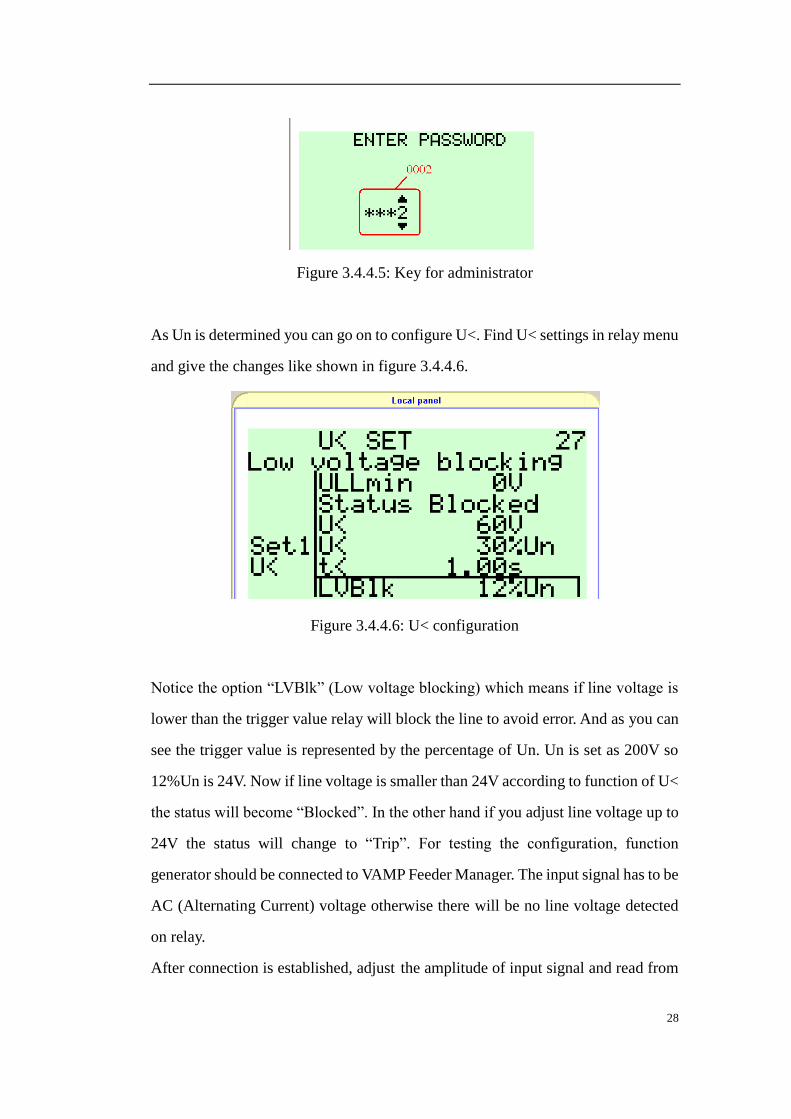
As Un is determined you can go on to configure U<. Find U< settings in relay menu
and give the changes like shown in figure 3.4.4.6.
Figure 3.4.4.6: U< configuration
Notice the option “LVBlk” (Low voltage blocking) which means if line voltage is
lower than the trigger value relay will block the line to avoid error. And as you can
see the trigger value is represented by the percentage of Un. Un is set as 200V so
12%Un is 24V. Now if line voltage is smaller than 24V according to function of U<
the status will become “Blocked”. In the other hand if you adjust line voltage up to
24V the status will change to “Trip”. For testing the configuration, function
generator should be connected to VAMP Feeder Manager. The input signal has to be
AC (Alternating Current) voltage otherwise there will be no line voltage detected
on relay.
After connection is established, adjust the amplitude of input signal and read from

29
relay. The line voltage is increasing or decreasing. At the beginning line voltage is
less than 24V:
Figure 3.4.4.7: Line voltage is less than 24V
Photo above shows the highest line voltage is 20V and it is less than trigger value.
So now the status for U< is “blocked” as shown below:
Figure 3.4.4.8: In U< status is “Blocked”
In this situation because of the block function relay is protecting lines. Next you try
to increase input voltage until it is more than trigger value so that relay will send an
alarm message to control system and change the status to “Trip”.

30
Figure 3.4.4.9: Trip
Line voltage now is 27V which is more than 24V and it clearly shows the light of
Alarm and Trip is on. All above prove us that under-voltage protection of this relay
is working fine but the data during transmission is not GOOSE yet. Last step is to
make VAMP relay accomplish the function with sending GOOSE message so that
you can capture GOOSE message to study.
To link U< function with GOOSE the same step as in exercise 2 has to be done
which is to enable the LN of U< in GCB1. But unfortunately there is no option in
GCB1 for LN of under-voltage. Another way to achieve the aim is to use Logical
Map. In Logical Map you use logical gate to connect U< function and GOOSE
output. But still you cannot directly link U< and GOOSE messages together so here
a “bridge” is needed to achieve our purpose which is VO6 (Virtual Output 6). VO6
must connect with U< function by an AND gate.
Figure 3.4.4.10: U< connected with VO6
Meanwhile VO6 should be enabled through IEC 61850 data map.
Figure 3.4.4.11: Enable VO6
Now new logic map is added which shows the Virtual Output in use. At this time,
though the principle is the same as exercise 2, you must add new logic element you
need to use like the voltage. This step is one of the most important one because it
affects the GOOSE message in wireshark.

31
After this setting, go to tag “GOOSE GCB1” in VAMPSET, set one more option to
signal as “VO6”.
Figure 3.4.4.12: Append VO6 to signal option
So far U< function is successfully connected to GOOSE messages. Also in the
“GOOSE configuration”, GCB1 must be used and check the MAC address and
Application ID carefully. Now as soon as relays trip/block the line you will get a
trail of GOOSE messages in Wireshark. The same as exercise 2, at the end of this
exercise IEC Simple Tester is needed to detect GOOSE messages. Before adjusting
line voltage over 24V which means line voltage is blocked you can find that value
in GOOSE detector is “F”.

32
Figure 3.4.4.13: Line Voltage is blocked
In the result there are three “F” appeared that is because in the basis of exercise 2
one more LN for VO6 is appended to GCB1. Checking signals in GCB1 you
discover there are three LNs enabled in signal option. Now the last “F” is for U<
function which you just build up. Now increase amplitude of function generator
until alarm message is sent by relay and status of line voltage is trip.

33
Figure 3.4.4.14: Line Voltage is trip
In the same time GOOSE message of alarm is sent GOOSE monitor changes value
from “F” to “T”.

34
4. Conclusion
The whole project was completed in a success. I and my team created three
laboratories in which we designed different configurations and different problems
to be solved In addition to that we created the instructions for the students which
will be used as preliminary instructions by the students. After completing the whole
project we tested the created work with a fresh student to solve the exercises using
the material we provided and he successfully without any problem solved all three
of them with no problem at all. This test is the guarantee for the work I did.
This thesis generalizes the information of GOOSE messages and VAMP Feeder
Manager 257 in form of laboratory experiment. The procedure during laboratory
exercises shows how IEC61850 works and how to use the relay. This is a
group-work project also; the entire team developed their own team spirit to confront
difficulties with team members together. The application of communicating
between relay and computer is a precious experiment for researchers in their future,
and it is also a preferable development for engineering and technology of the future.
This project will equip the upcoming student with the latest technology being used
for substation automation and will provide adequate information to those who want
to proceed with these devices in their future.

35
5. References
Ref 1: Vamp Feeder/Motor Manager series VAMP 230 VAMP 245 VAMP 255
VAMP 257, Vaasa Electronics Group
Features of IEC 61850 Source Code Libraries, Triangle MicroWorks Inc.
Testing in Substations with IEC 61850- Latest Developments and Advanced
Possibilities, Thomas SCHOSSIG OMICRON electronics GmbH
MMS and ASN.1 Encodings, Herbert Falk (SISCO) and Dr. Martin Burns
(Hypertek), 06.07.1996
IEC 61850 part5-8, IEC
IEC 61850 Communication Networks and Systems In Substations, SIPSEP 2004
VAMP 257 Feeder and motor manager Operation and configuration instructions
Technical description
<http://www.vamp.fi/Manuals/English/VM257.EN005.pdf >