Developing Correct Safety Critical, Hybrid, Embedded Systems
13
UNCLASSIFIED Defense Technical Information Center Compilation Part Notice ADPO10880 TITLE: Developing Correct Safety Critical, Hybrid, Embedded Systems DISTRIBUTION: Approved for public release, distribution unlimited This paper is part of the following report: TITLE: New Information Processing Techniques for Military Systems [les Nouvelles techniques de traitement de l'information pour les systemes militaires] To order the complete compilation report, use: ADA391919 The component part is provided here to allow users access to individually authored sections f proceedings, annals, symposia, ect. However, the component should be considered within he context of the overall compilation report and not as a stand-alone technical report. The following component part numbers comprise the compilation report: ADP010865 thru ADP010894 UNCLASSIFIED
Transcript of Developing Correct Safety Critical, Hybrid, Embedded Systems

UNCLASSIFIED
Defense Technical Information CenterCompilation Part Notice
ADPO10880TITLE: Developing Correct Safety Critical,
Hybrid, Embedded Systems
DISTRIBUTION: Approved for public release, distribution unlimited
This paper is part of the following report:
TITLE: New Information Processing Techniques forMilitary Systems [les Nouvelles techniques detraitement de l'information pour les systemesmilitaires]
To order the complete compilation report, use: ADA391919
The component part is provided here to allow users access to individually authored sections
f proceedings, annals, symposia, ect. However, the component should be considered within
he context of the overall compilation report and not as a stand-alone technical report.
The following component part numbers comprise the compilation report:
ADP010865 thru ADP010894
UNCLASSIFIED

1S-1
Developing Correct Safety Critical, Hybrid, Embedded Systems*
Alexander Pretschner, Oscar Slotosch, Thomas StaunerInstitut fuir Informatik, Technische Universitd.t Miinchen
Arcisstrafe 21, 80290 Miinchen, Germany
{pretschn, slotosch, stauner} in. turn. de
Abstract means of formal techniques.
AutoFocus. Discrete systems are modeled usingSeveral aspects of the development process of correct graphical description techniques for structure, be-safety critical discrete and hybrid embedded systems havior, and interaction. In this paper we shortlyare discussed. The general process and its support present AuToFocus, a tool prototype for model-by the CASE tool AuToFocus is outlined. This is ing discrete embedded systems that we will use toillustrated along the lines of a simplified version of model a hybrid system, namely a simplified versionNASA's Mars Polar Lander. It is argued that spe- of NASA's crashed Mars Polar Lander. The mod-cific aspects of hybrid systems do require the modifi- els are based on a common formal semantics and cancation of classical theories on software development, therefore be used to support the development processand these modifications are discussed. The paper from the requirements engineering phase throughoutconcludes by focusing on one part of the develop- the test phase. The existing features of AUToFo-ment process, namely testing. A novel approach to cus suffice to model discretizations of hybrid sys-the automated generation of test cases for discrete as t6 ms. These discretizations, however, usually alterwell as hybrid systems is presented. The Mars lan- the model which reduces the set of properties thatder's crash serves as an example for the derivation of can be derived from a system model.meaningful test cases.Keywords. Reactive Systems, Validation, Devel- Hybrid systems. The development of hybrid sys-opment Process, Automatic Test Case Generation, tems is an interdisciplinary task. Usually engineersCASE from different disciplines are involved and must dis-
cuss their designs. Graphical description techniquesare one element very useful to support this commu-
I Introduction nication. Just as for safety critical discrete systems,it is furthermore desirable to apply a high degree ofmathematical rigor in the development of safety criti-
Safety critical systems. Developing correct safety cal hybrid systems. Today formal methods for hybridcritical software for hybrid, embedded systems is a systems are still an active area of research, and theredifficult and error prone task. The functional re- are hardly any tools available which could yet be usedliability of the resulting systems is at least as im- in industrial practice. In this paper we therefore out-portant as security aspects. High quality of the re- ;w& ýPm -Frw.,2& Lv-•, inn wj•e:t,•+- ý,az; ?.Ssulting systems can only be achieved using a well -AjTE•PDjs) ýýn 11-vYn wi fb w•rxetq frv ra-structured development process. We present a de- tinuous systems in a development process for hybridvelopment process that integrates many methods for systems that is feasible today. We discuss shortcom-quality assurance for discrete systems. In this paper, ings of this method and outline how our work on by-discrete systems refer to discrete event systems. How- brid modeling and validation leads to an integratedever, those discrete event specification techniques we development process for hybrid systems which is closeconsider also have a discrete-time execution model. to the current AuToFocus approach for discrete sys-For mixed discrete-continuous systems (or "hybrid tems.systems") we discuss elements necessary to obtain asimilar integrated process, taking into account dis- Testing. Much work has been devoted to check-crete as well as continuous aspects. The process for ing validity and consistency of a specification. By
discrete systems is an extension of the V-model [22]. now, testing is the only practicable, scalable meansIt is based on system models that are validated by of validating the conformance of an implementation
w.r.t. its specification, even though Dijkstra's popu-*This work was supported with funds of the Deutsche lar remark that testing can only reveal the presence
Forschungsgemeinschaft under reference numbers Br 887/9 but never the absence of errors undoubtedly holdsand Be 1055/7-2 within the priority programs Design and de-sign methodology of embedded systems and KONDISK [10], true. We discuss the role of testing as a comple-and by the DASA. ment to formal methods and present a novel approach
Paper presented at the RTO IST Symposium on "New Information Processing Techniques for Military Systems",held in Istanbul, Turkey, 9-11 October 2000, andpublished in RTO MP-049.

15-2
based on Constraint Logic Programming to automat- present, CASE tools with useful semantic checks areically generating test cases for discrete as well as hy- not available. Recently, model checking tools havebrid systems. Experimental results from a case study been connected to tools based on statecharts or SDL,of a safety critical system, the Mars Polar Lander, are but due to the complex semantics of these languagesdiscussed. We also take into account the integration without practical relevance. A systematic generationof testing processes into the development process of of test sequences is also not available. Checking ad-safety critical systems and our method's benefits and equacy is reduced to simulation facilities.shortcomings. AuToFocus, on the other hand, also allows for
Overview. The remainder of this paper is orga- semantic validation. These validation techniques arenized as follows. In section 2, we briefly discuss prin- based on the simple and intuitive semantics of AUTO-
ciples of a software development process for reliable Focus [21], and can be used to support model-based
discrete systems. Section 3 describes shortcomings development steps according to the V-model within
of this classical approach w.r.t. hybrid systems and all phases; in particular, testing is supported at the
suggests modifications that remedy these shortcom- design, implementation, integration and system re-
ings. Specifically, we argue for integrated descrip- quirements levels.
tion techniques right from the beginning. Section 4 Modeling hybrid systems with AUToFocus is done
then describes the CASE tool AuToFocus and its by a simple discretization of the continuous behavior,
description elements. Since so far there is no tool sup- and this approach allows to integrate discrete and
port for the integrated development process of Sec. 3, continuous parts in a single model (as will be shown
section 5 exemplifies the use of a discrete modeling in the example in Section 5).
tool for a hybrid system, the Mars Lander. Section 6discusses the generation of test cases for discrete as 3 Hybrid Systemswell as hybrid systems along the lines of our example.Section 7 concludes this paper. Related work is cited In this section we outline how a conventional formalin the respective sections. tool for discrete systems, such as AUToFocus, can
be used within the development of hybrid systems.We discuss advantages and drawbacks of such an ap-
2 Notes on the Development proach, and present a more visionary approach notProcess yet supported by tools. The new approach is sup-
posed to prevent these drawbacks. It results from
For safety critical systems, we advocate a develop- carrying over ideas like graphical specification with
ment process that heavily relies on models. In this different systems views and model based validation
process, models are developed in phases known from based on formal methods to hybrid systems. A cen-
conventional software development processes. These tral characteristic of the proposed approach is that
models are then validated, and the last step is to gen- it is based on notations that have a clearly defined
erate code from them in order to get an executable semantics.
implementation. A last validation step consists of A conventional development process. A con-testing the developed systems in interaction with ventional development process for hybrid systemstheir environment, for example together with other builds upon isolated description techniques for purelycomponents or hardware. Model validation is the discrete and purely continuous components. Pop-key factor for producing highly reliable programs for ular in industry are tool couplings such as us-safety critical systems. Useful models should describe ing Statemate together with Matrixx or the MAT-the developed system from different views by means LAB/Simulink/StateFlow environment [11, 9]. Forof various hierarchical diagrams. The diagrams can the development of safety critical systems we advo-be used to capture requirements, architecture, design cate the use of formal methods and notations wher-and implementation decisions, and to represent test ever possible. This hinders the use of current com-sequences. inercial tools like Statemate, ObjectGeode, Rational
Model validation may be seen as checking consis- RoseRT or Stateflow. Their notations only have atency. It can be applied at several levels: syntac- formal syntax, but the semantics remains imprecisetic consistency (checking names), completeness con- and ambiguous, or very complex. A semantics forsistency (checking references and types), semantic the coupling with continuous tools in not definedconsistency (checking refinement relations), and ade- anyway. However, tools like AuToFocus are avail-quacy [28, 4], i.e., conformance of a model with possi- able which support the design of discrete systemsbly informal requirements. Many available tools per- based on formal notations such as architecture de-form a syntax check with fixed built-in routines. For scriptions, extended automata and MSC dialects [23].this purpose, modern tools use the object constraint For continuous systems there also are analysis andlanguage OCL [38] of UML which, in principle, could simulation tools based on block diagram notations,also be used to check completeness of the models. At e.g. MATLAB [36]. Note that we regard block di-

15-3
requirements,system environment
prequirements tspeciqicatuon, insrmal validatio
environment model Sar, reoneueat(mbbsmal thx, SSDs .... q
z7• "'-..•enlorced early paritioning
a w discrete parts continuous parts conventionalh toS T'D,, ke i(block daga ms) t chiiiques
i odel code
requirements,
systehn environment
hybrid descripoion requirepaens specificatione, om vldhadion
b wrte onuigteeeitn olse Figurer tmdesine hstpefo:rm aI vauidat of eeomn
techniques (Hischare s HySCs )eps and refwinement
the discrete p a n iflate partitioning
discrete parts hybrid parts continuous partsi...r..o (syCharts) p (block diagrams)conventional conv entoal
techniques i techniques
Figure 1: A conventional development process (top) and an integrated development process with hybrid de-scription techniques (bottom).
agram descriptions of continuous systems as formal Drawbacks. So far, the only currently availablehere, because a mathematical model can be associ- technique for examining properties of the mixed sys-ated with individual blocks and their interconnection tern is simulation. There are hardly any analyticalin a straightforward manner. (Nevertheless, the user methods regarding the mixed model and there are nohas to keep in mind that the selection of integration techniques which support design modifications thatalgorithms for simulation can have a great impact affect both parts of the model. In fact such mood-on simulation results and can cause them to differ ifications could necessitate a redesign of the wholestrongly from the mathematical model.) As soon as model.the system under development is partitioned into dis-crete and continuous parts, a formal specification can Furthermore, in such a development process abe written down using these existing tools, see Figure designer has to perform a number of development1, top. Well-known techniques from the discrete and steps informally, i.e., without documenting them
continuous world can then be applied to the respec- with clearly defined notations, before a clearly doc-tive parts of the model. For instance, model checking umented process can start, i.e., a process relying onand automatic test case generation may be used for formal description techniques. In particular, thesethe discrete part and analysis of eigenvalues for the steps include partitioning the design into discrete andcontinuous part. continuous parts which may involve an (implicit) dis-
cretization of some parts. This is unsatisfactory since

15-4
the partitioning decisions may be difficult to alter allows to obtain greater confidence in the model be-later on. Apart from that, the resulting coupled dis- fore a partitioning. Namely, testing and model check-crete continuous model often is not natural for some ing techniques can be used to analyze requirementscomponents of a hybrid system. For example, analog and refinement techniques can be used to guaranteeto digital (AD) and digital to analog (DA) converters, some requirements by construction. By postponingand in some systems the environment, are inherently implementation related questions changing require-hybrid components. ments can more easily be taken into account. Thus,
errors made in the initial development phases can beRecommendation. As no formal hybrid nota- found earlier and are therefore cheaper to correct.tions with tool support that is suitable in practice The development process we propose in Figure 1,are available today, there currently is no real alter- bottom, is based on description techniques devel-native to the outlined conventional development pro- oped within our group in the last years. For re-cess. We therefore propose to use informal text cou- quirements specification and environment modelingpled with formal descriptions where possible in this it uses the MSC-like notation HySC [15], and theprocess: Writing down mathematical formulae ex- combination of architecture diagrams and a hybridpressing hybrid behavior directly is hardly reasonable automata variant which is subsumed in HyChartsfor bigger systems. In the context of AUToFocus [16]. A methodological transition from HySCs to Hy-we recommend using architecture descriptions (SSDs, Charts is ongoing work (for similar work on discretesee Sec. 4) already during the requirements capture systems see [24]). Succeeding steps in the figure re-phase and to describe the behavior of system com- fer to HyCharts rather than to HySCs. As notationsponents informally with text or, where practicable, for the discrete and the continuous part we proposewith mathematical formulae, until the partitioning DiCharts [17], a discrete-time variant of HyCharts,into discrete and continuous components has been and (continuous time) block diagrams, repectively,performed. Figure 1, top, outlines the conventional taht can be integrated easily into the HyChart nota-process and its support by AuToFocus. For the dis- tion.crete part the model checking and testing techniques Note that the aspect of postponing the partitioningalready implemented in the tool can be employed, of a system into discrete and continuous parts is re-They enable a more rigorous analysis of the discrete lated to the area of hardware/software codesign [6].patthan what is possible with other tools for dis- ltdt h rao adaesfwr oein[]part tThere, the decision on which parts of a system arecrete systems that do not have a formal semantics. implemented in hardware and software is postponed
Outlook: An integrated development pro- to later phases. However, unlike hardware/softwarecess. In a development process with hybrid descrip- codesign the partitioning into discrete and continu-tion techniques, such as the one depicted in Figure 1, ous components proposed here does not yet implybottom, the designer is able to formally specify mixed how the components are implemented. The discretediscrete continuous models at early stages of the de- part could be implemented in software or on digi-velopment process. In the context of formal methods, tal hardware, the continuous part can be turned intowe refer to "refinement" as altering (or augmenting) a discrete-time model and implemented in softwarea system's functionality without violating properties (or digital hardware), or it could be implemented inthat have already been established. If validation and analog hardware.transformation techniques, such as simulation and While there is hardly any tool support for the in-refinement, are available for these description tech- tegrated process today, a close coupling of discreteniques, the model can be systematically designed to and continuous notations in the HyChart style is im-meet those system requirements which affect its dis- plemented in the MaSiEd tool [1], which also allowscrete as well as its continuous aspects. Rudimentary simulation. The HyTech tool [18] (or other tools, e.g.,versions of such techniques already exist and are an Uppaal or Kronos) which offers model checking of hy-area of current research (e.g. [3, 10]). In later steps brid models is another element needed as support forthe model can be refined into discrete, continuous, an integrated development process. Presently, how-and possibly some remaining hybrid submodels. For ever, its application is limited due to scalability prob-the discrete and continuous submodels conventional lems and deficits of the underlying hybrid automatatechniques can then be used to realize those proper- model [29]. Promising tool approaches for the futureties which only affect the respective part. Thus, the should couple analysis algorithms like those imple-availability of formal hybrid description techniques mented in HyTech with modular graphical descrip-and supporting methods for them pushes the point at tion techniques, e.g. HyCharts, in comprehensive toolwhich systematic development, i.e. development with frameworks, such as accomplished with AuToFocusformal description techniques, can begin towards the for discrete systems.beginning of the analysis phase. A partitioning into Note that the development process for hybrid sys-discrete and continuous submodels can be postponed tem proposed in [9] can be regarded as an intermnedi-towards subsequent development phases. Such a de- ary between the two processes outlined here. There,velopment process with hybrid description techniques the authors propose to complement block diagrams

15-5
and automata-based notations with formal specifica- statements are copied to the appropriate ports andtions using Z [34]. the local variables are set according to the postcon-
dition. Actually the postcondition consists of a set ofactions that assign new values to local variables, i.e.,
4 AUTOFOCuS the assignments set the automaton's new data state.
Communication semantics. AUToFocus com-AUToFocus [19, 20] is a tool for graphically speci- ponents have a common global clock, i.e., they allfying embedded systems. It supports different views perform their computations simultaneously. The cy-on the system model: structure, behavior, interac- cle of a composed system consists of two steps: Firsttion, and data type view. Each view concentrates on each component reads the values on its input portsa fixed part of the specified model. and computes new values for local variables and out-
Structural view: SSDs. In AuToFocus, a dis- put ports. After the clock tick, the new values are
tributed system is a network of components, possibly copied to the output ports where they can be ac-
connected one to another, and communicating via so- cessed immediately via the input ports of connected
called channels. The partners of all interactions are components and the cycle is repeated. This results
components which are specified in System Structure in a time-synchronous communication scheme with
Diagrams (SSDs). Figure 4 shows a typical SSD. In buffer size 1. Values on the output ports are copied
this static view of the system and its environment, over the channels to the appropriate input ports and
rectangles represent components, and directed lines the cycle is repeated. This results in a non blocking
visualize channels between them. Both are labeled synchronous communication.
with a name. Channels are typed and directed, and Interaction view: MSCs. Message Sequencethey are connected to components at special entry Charts (MSCs) are used to describe the interactionand exit points, so called ports. Ports are visualized of components. In contrast to Message Sequenceby filled and empty circles drawn on the outline (the Charts as defined in [23], AUToFoCus MSCs referinterface) of a component. As SSDs can be hierar- to time-synchronous systems. In the following, thechically refined, ports may be connected to the inside term MSC always denotes these time-synchronous se-of a component. Accordingly, ports which are not re- quence charts. Progress of time is explicitly modeledlated to a component are meant to be part of unspec- by ticks which are represented by dashed lines. Allified components which define the outside world and actions between two successive ticks are consideredthus the component's interface to its environment, to occur simultaneously, i.e., the order of these ac-Components can have local variables to store values; tions is meaningless. An action in an MSC describesthese variables can be used to describe the behavior a message that is sent via a channel from one com-and the interaction of components. ponent to another.
Behavioral view: STDs. The behavior of an Au- MSCs can be used to describe requirements, sim-
ToFocus component is described by a State Transi- ulation traces, counter examples (from model check-
tion Diagram (STD). Figures 5 and 6 show typical ing), and test sequences. Figures 7 and 8 show a
STDs. Initial states are marked with a black dot. typical test case specification as well as a satisfyingtest case that satisfies it.
An STD consists of a set of control states, transi-
tions and local variables. The set of local variables Datatype view: DTDs. For the specification ofbuilds the automaton's data state. Hence, the inter- user defined data types and functions AUToFocusnal state of a component consists of the automaton's provides Data Type Definitions (DTDs). Definitionscontrol as well as its data state. A transition can in DTDs are written in a functional style. For hybridbe complemented with several annotations: a label, systems functions with continuous ranges can be de-a precondition, input statements, output statements, fined, for instance:and a postcondition, separated by colons. The pre- const GMars = 3.73;condition is a boolean expression that can refer to fun speed(last:Floatdt:Float)local variables and transition variables. Transition = last+GMars*dt.variables are bound by input statements, and theirlife-cycle is restricted to one execution of the tran- Features of AuToFocus. In addition to its model-sition. Input statements consist of a channel name ing capabilities, AUToFocus allows for checking con-followed by a question mark and a pattern. An out- sistency between views as well as simulating modelsput statement is a channel name and an expression (using OCL). For the German BSI (Federal Agencyseparated by an exclamation mark. The expression for Security in Information Technology) several val-on the output statement can refer to both local and idation techniques have been integrated into AuTo-transition variables. A transition can fire if the pre- Focus [33]. The result is a model validation frame-condition holds and the patterns on the input state- work that supportsments match the values read from the input. Afterexecution of the transition the values in the output 0 model checking and bounded model checking to
15-6
check temporal properties (invariants) [31], force where rhe is the lander's (negative) change of"mass and vf the (negative, approximately constant)
m abstraction techniques to safely reduce complex rocket's exhaust speed. By ignoring friction effectsmodels to simpler ones, and letting h(t) denote the lander's height one de-
"• interactive theorem proving techniques to verify rives h , gmars - 4 "Vf and thus the lander's
arbitrary security requirements, and vertical speed (Fig. 2-3) from F(t) ; me(t) •h =
"* systematic generation of test sequences and test Fw(t) - Fthr(t). For simplicity's sake, horizontalcases [39, 26, 27]. forces have been ignored. Oversimplifying again, we
furthermore assume a simple PD controller for the
All these validation techniques are based on the sim- lander, modeled by fhi j C1 - (vf(t) - Vreq) + c2 * V,
ple and intuitive semantics of AUToFOCuS [21], and for adequate gains c1 , c2 and the lander's requiredcan be used to support model-based development speed, Vreq. This yields the system's second descrip-steps. This framework also allows to generate Java tive equation (Fig. 2-4) for this state. The controland C code from the validated models in order to get variable is thus rht (or fim, respectively) which re-executable implementations. flects an increase or decrease in fuel to be burnt.
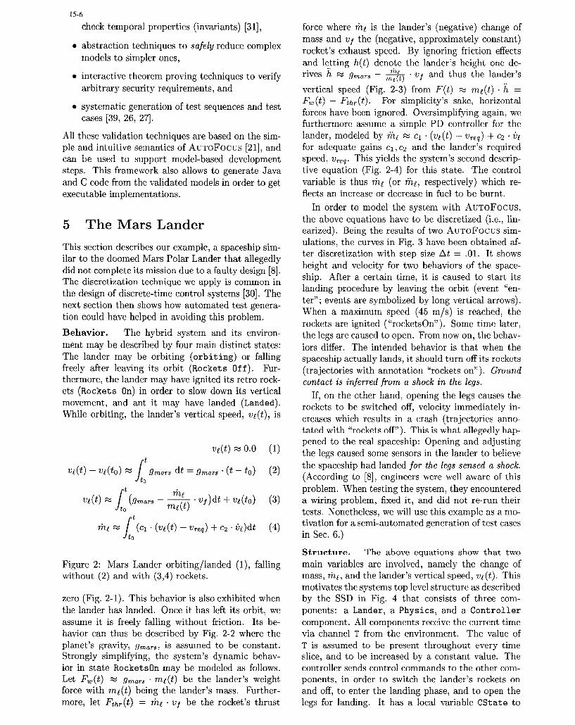
In order to model the system with AUTOFocus,5 The Mars Lander the above equations have to be discretized (i.e., lin-
earized). Being the results of two AuToFocus sim-
This section describes our example, a spaceship sim- ulations, the curves in Fig. 3 have been obtained af-
ilar to the doomed Mars Polar Lander that allegedly ter discretization with step size At = .01. It shows
did not complete its mission due to a faulty design [8]. height and velocity for two behaviors of the space-
The discretization technique we apply is common in ship. After a certain time, it is caused to start its
the design of discrete-time control systems [30]. The landing procedure by leaving the orbit (event "en-
next section then shows how automated test genera- ter"; events are symbolized by long vertical arrows).
tion could have helped in avoiding this problem. When a maximum speed (45 m/s) is reached, therockets are ignited ("rocketsOn"). Some time later,
Behavior. The hybrid system and its environ- the legs are caused to open. From now on, the behiav-meit may be described by four main distinct states: iors differ. The intended behavior is that when theThe lander may be orbiting (orbiting) or falling spaceship actually lands, it should turn off its rocketsfreely after leaving its orbit (Rockets Off). Fur- (trajectories with annotation "rockets on"). Groundthermore, the lander may have ignited its retro rock- contact is inferred from a shock in the legs.ets (Rockets On) in order to slow down its vertical If, on the other hand, opening the legs causes themovement, and ant it may have landed (Landed). rockets to be switched off, velocity immediately in-While orbiting, the lander's vertical speed, ve(t), is creases which results in a crash (trajectories anno-
tated with "rockets off"). This is what allegedly hap-pened to the real spaceship: Opening and adjusting
ve(t) t 0.0 (1) the legs caused some sensors in the lander to believe
Vt (t) - v1 (to) ;Z / ma dt = gmars * (t - to) (2) the spaceship had landed for the legs sensed a shock.1( -(According to [8], engineers were well aware of this
e. problem. When testing the system, they encounteredv(t) (groas -- M . vf )dt + ve(to) (3) a wiring problem, fixed it, and did not re-run their
f, mef(t) tests. Nonetheless, we will use this example as a mo-meq ; I (cl . (ve(t) - Vreq) + C2 " e)dt (4) tivation for a semi-automated generation of test cases
to in Sec. 6.)
Structure. The above equations show that twoFigure 2: Mars Lander orbiting/landed (1), falling main variables are involved, namely the change ofwithout (2) and with (3,4) rockets. mass, rhq, and the lander's vertical speed, vj(t). This
motivates the systems top level structure as describedzero (Fig. 2-1). This behavior is also exhibited when by the SSD in Fig. 4 that consists of three com-the lander has landed. Once it has left its orbit, we ponents: a Lander, a Physics, and a Controllerassume it is freely falling without friction. Its be- component. All components receive the current timehavior can thus be described by Fig. 2-2 where the via channel T from the environment. The value ofplanet's gravity, gmars, is assumed to be constant. T is assumed to be present throughout every timeStrongly simplifying, the system's dynamic behav- slice, and to be increased by a constant value. Theior in state RocketsOn may be modeled as follows, controller sends control commands to the other comn-Let Fw(t) ; g mars - me(t) be the lander's weight ponents, in order to switch the lander's rockets onforce with me(t) being the lander's mass. Further- and off, to enter the landing phase, and to open themore, let Fthr(t) = me " vf be the rocket's thrust legs for landing. It has a local variable CState to

15-7T Aener fckts openLegs
nnter O RcktO) landed (crashed) landed900 , ,-------- ,
"t1 Ovelocity (crash)800 height (crash)-
10'velocity .......700 height ..........700\
600
rockets off500
400
300 rockets on
200 1100
0
0 10 20 30 40 50 60 70time (s)
600 - - r-
500 .......
40l712*mnass (crash)......
400 c off 10*0massdot (crash) -------1/2*mass ........
300 -1 O0*massdot
rockets on
200
100
S.............. ......................................
10 ..................-300.......
-400 1-0 I 1 20 30 40 50 60 70
time (s)
Figure 3: Spaceship crashes and lands.
record the spaceship's state since it needs to know become more complex. The behavior of componentwhen to issue which command. The initial value of Physics is separated into two states (see Fig. 5).this variable is Waiting; the type of this variable State Control Off just outputs the current speedis a DTD data CState = Waiting I Ron I Roff. (and does not react to changes of mass), whereas inWhen port Sensor receives True, this should (!) in- state Control On, the new speed is computed fromdicate that the lander has sensed ground contact, and the last speed and the actual change in mass (Eq. 3).in turn its rockets will be switched off. Component Physics has several local variables to
store past values, used for integration, and differen-muthelly diffe denti e Ion ofder Fig com- e ad 2 a-4 a tiation, LastT:Float, for instance, to compute time
mutually dependent. In order to compute the val- differences. The denotation of the transition labelsues independently, the computation has to be sepa- in Fig. 5 consists of functional terms computing newrated into two subcomponents, namely Lander and values according to the discretized equations. ThePhysics. The main interaction is between Lander, behavior of component Lander is separated into fourand Physics: the environment sends the current ve- states (see Fig. 6), each representing a differentiallocity to the lander (channel V), and the lander, in equation or the respective computation of new val-turn, sends its change in mass to the environment ues (mainly for the local variables: LastT, LastV,(channel Mdot). Channel Speed is only necessary for LastM, Lastf, and Legsfut) and for the output Mdot.the initial value of the control process. Lander and In the initial state Orbiting the lander waits for thePhysics could have been grouped together into one command enter from the controller (received at porthierarchic component. This is advisable if systems

15-8
:Control'; T?t:Heigtrl'LastH;Speed LastV:LastT = t
diff. equation (1)
:Controlenter; T?t:Height!LastH;SpeedfLastV:LastT T
start da *ng
diff. equations (3,4) ld dift. equation (2)S-start Rockets
fRockets Off free fallingfree falling
[(LastH = 00)::Speed010. ; Height!00: O :t~uch~ n touc, doc wn
touch n
lne diff. equation (1)
Figure 6: Behavior of Component Lander
Local Variables: working
CnState Waling
open legs working Control OnIL j Height:Float
Control.:.om andsr
Sensor Bool T:Float ýtop controlnsoTIConfrol:Co mds restarting
V:1Float Speed:FloatT 71 d f:Foat
Y :Conrol P1e.: Co tr l ..
C: :T?t;Control?;Speed?v::LastT=t;LastV=vFigure 4: System Structure Diagram
Figure 5: Behavior of Component Physics
Control). Unless no enter command is present, ini-tial values are sent to the environment. This is donewithin the transition labeled flying and the follow- This last transition has no precondition (sinceing semantics: t>LastT is a general assumption on time).
The states Rockets On and Rockets Of f control"* input pattern Control? denotes no input on the lander during the landing phase (with and with-
port Control, out boosters); control commands RocketsOn and
"Rocket sOff from port Control can be used to switch* input pattern Tt denotes that the input on port between the two respective equations. If the height
T is bound to transition variable t, is less or equal to zero in one of the states, the lander
reaches the final state landed."* output patterns Height !LastH, and
Speed! LastV denote the sending of the current Shortcomings. Suitably discretizing a continu-values of the variables to the output ports, ous model is a difficult problem. We chose a simple
piecewise linearization with trapezoidal approxima-"• action LastT = t stores the value t into the lo- tion. Problems with this approach include a con-
cal variable LastT. servative determination of At as well as meaningful

15-9
error estimations. Thus far, we use the same At for case specifications can, for instance, be written downall components (in accordance with user-defined step as mathematical formulas [12], formal specificationssizes for each component). This approach may re- [37, 5, 32], as MSCs [13, 26, 27, 39], as partial I/Osult in efficiency problems, but it solves the problem traces or constraints over them [26, 27, 7]. A test casementioned below for communicating components in- is an artifact that satisfies a given test case specifi-tegrating over a same variable in the case this variable cation and may be formulated in the same forms asis t. The automatic generation of discretized systems test case specifications. A test sequence, finally, is anfrom continuous equations is subject of ongoing work. executable test case, e.g., an I/O trace. [27] discussesEspecially methods are developed to break systems of this terminological framework.differential equations into single components, to de- Our work aims at (semi-) automatically derivingtermine appropriate discretization methods, and to test cases from test case specifications that may beto find good timing rates for the components. used for both, interactively white box testing a spec-
ification and (semi-)automatically black box testingan implementation. As indicated above, the interac-
6 Testing tive part plays an important role in the developmentprocess. Even though it is undoubtedly true that a
Approaches to ensure a system's reliability include sst s le though t hougter bre t
validating a model w.r.t. its specification as well as syi pem ented or odele weobelieve that im
checking an implementation's conformance w.r.t. the isni ande inte racti etesting h elin ta ndingla
specification. Formal methods, such as model check- model. This is related to the rapid prototyping ap-
ing, allow for determining a system's correctness in proach in software engineering; we even see simula-
terms of user defined properties usually formulated in tioas a s of theesing proessi[6l2]I tion as a specialization of the testing process [26, 27].an (unintuitive) logic, e.g., the Linear time TemporalLogic LTL. Without suitable (and usually hard to de- However, it is worth emphasizing that most likely
Logi LT. Wihou suiabl (ad usall har tode- none of the commonly used approaches to quality as-termine) abstractions, model checking is restricted to no e of th commoned appras to quality -finie satespacs wich forinsanc, tyicaly row surance will do it alone. In contrast to formal meth-finite state spaces which, for instance, typically growan inherently incomplete process. Asexponentially with the number of variables involved. ods tetin ds an ihrnt icolet e pro casNot urpisigly indstral pplcabiityhasnotyet formal methods yet do not scale to real size applica-N ot su rp risin gly, in du strial app licability h as not yet ti n , h s d e c t h a to b a c p ed ut or e nbeen achieved. In the following, we describe how a tins, tis thas to be ace t tesinclassical approach to quality assurance, namely test- n i p remar thatseng caningis upprtedby UTOOCU. Weadvcat an only reveal the presence but never the absence of er-ing, is supported by A uT o F o c u s. W e advocate anro s a o ap l e to f m l m th d : O e c n n yintegration of mathematically complete techniques rors also applies to formal methods: One can only(model checking) with testing. In addition to specify- check properties that have been formulated by a hu-
ing test cases during the design phase, testing should man. This process, however, obviously is also neces-
also be done interactively, for certain errors can only sarily incomplete.
be revealed by "playing around" with the model. Test case specification. The specification ofThis kind of testing may thus be seen as a debugging test cases or properties to be checked requires in-aid. This is, in fact, the case for most of the spec- tuitive and, if possible, graphical description tech-tacular software faults the model checking/theorem niques. One problem with formal techniques surelyproving communities use as a motivation for their lies in the fact that without an intense formal edu-work. The discussion of test management strategies cation properties are hard to express in formalismsand particular techniques such as mutation analysis such as LTL or the Temporal Logic of Actions TLAand fault injection is beyond the scope of this article [25]. We hence advocate the use of a variant of Mes-and thus omitted. sage Sequence Charts [23] for the specification of test
Applicability and Terminology. We distinguish cases [13, 39, 26, 27]. MSCs (HySCs) are augmented
between possibly informal requirements, a specifica- with elements for talking about states in condition
tion which is called a model if it is written down boxes [15] as well as constructs for expressing itera-
formally (e.g., in AuToFocus), and an implemen- tion and the necessity of certain transitions to fire.
tation. Testing an implementation is usually done The identification of typical test purposes, e.g., caus-
w.r.t. its specification, e.g., [32, 26, 27]; the speci- ing the system to output certain values, reaching
fication is thus considered to be correct. Obviously, states, executing transition sequences [39], led to the
this is a strong and usually unrealistic assumption. incorporation of these language constructs.However, we think it is one necessary step. The tech- An important concept is that of negation (negatingniques sketched below and explained in more detail transitions, the reachability of states, or forbiddingin [26, 27, 39] allow for the determination of test se- certain inputs or outputs). However, a suitable se-quences on the grounds of a test case specification. mantics for MSCs in the context of test cases seemsA test case specification is the formalization of some to be incomplete in the sense that between two el-test purpose, i.e., reach a particular state or cause ements in an MSC, arbitrarily many others may bethe system to throw a particular exception. Test present. Apparently the formal definition of a se-

15-10
mantics for negation in this context is not obvious[24] and subject of ongoing work.
In AUTOFOCUS, test cases may be specified byboth LTL formulas and MSCs. In the following, Lander: Orbitingwe focus on the derivation of test cases from sys-tem and test case specifications. In the remainderof this section, the system specification should be Height!h;h>-1O.O
thought of as an AUToFocus model, and the test Icase specification is formulated using MSCs. Coin- Speedls; s>o.01
puted test cases (I/O sequences) are displayed in theform of MSCs themselves for inspection by a human(or comparison with expected test results, i.e., corre-spondence of the model's output with the output as Lander: Landeddescribed in the test case specification). Note that in
this paper we concentrate on testing a specificationand do not take into account testing implementationseven though computed test sequences can be fed into Figure 7: Test case spec.: Reach state landed.an implementation for conformance testing with thespecification. checking [2] can be found in [39].
Testing discrete systems. This paragraph brieflydescribes the generation of test cases from test case Testing hybrid systems. In principle, the abovespecifications by means of Constraint Logic Program- automatic CLP based generation of test sequences isming (CLP) as well as of propositional logic. These also applicable to mixed discrete-continuous systems,methods automatically derive test sequences from for numerical or algebraic solvers can easily be con-system and test case specifications. nected to the CLP system. Yet, assuming that con-
CLP is the result of integrating two declarative tinuous activities take place within particular states
programming paradigms, namely logic and constraint of the system and that there is a continuous data flow
programming. Distinctive features include inverta- between components, a number of problems arise.
bility of functions, the use of free (logical) variables First of all, it is not clear how a continuous data flow
that may be bound during program execution, built- can be simulated on ordinary computers (in control
in search mechanisms - backtracking -, and a seman- systems, however, there indeed is a continuous flow of
tics based not only on terms but rather on arbitrary data). Secondly, numerical solvers also discretize dif-
domains. It turned out that AUToFocus models ferential equations and solve these equations with dif-
can very naturally be translated into CLP languages. ferent, possibly even dynamic, integration step sizes.
The idea is to feed the executable model with partial It is not clear how to handle the situation where one
I/O traces and make the test case generation sys- component triggers a transition dependent on, e.g.,
tern create actual test cases (possibly partial I/0 se- the global time. Assume that two components run at
quences subject to certain constraints, e.g. ranges for different speeds, i.e., with different integration step
variables) by relying on the above mentioned built-in sizes. If one component integrates over a common
search mechanism and by using logical variables. By variable and meanwhile receives a value for exactly
imposing constraints (e.g., in the forms of MSCs) on this variable that has been determined according to
the set of all possible system execution, the search an earlier time, it has to stop its integration process
space can significantly be reduced. Further analyses and to step back. This results in severe methodical
such as automated interval analyses or (manually de- as well as efficiency problems, both of which are sub-
rived) classification trees [14] for variables then allow ject of ongoing work, based on (1) the semantics for
for the determination of meaningful test sequences hybrid systems as defined in [35] and (2) a modifica-
(taking into account, for instance, range boundaries tion of the AUToFocus semantics where continuous
that yield equivalence classes to be tested). [26, 27] activities do not take place on transitions but rather
contain a more detailed description of this approach. within states. This applies only to hybrid testingsince real time simulation forbids re-calculating cer-Testing based on propositional logic is suitable tmvral onais
only for small finite systems (in particular, for sys-
tems with small, finite variable ranges). AUToFocus Example: Testing the lander. In accordancemodels as well as test case specifications are trans- with these considerations, so far the methods for de-lated into propositional logic and combined into a sin- riving test cases described above have only been im-gle formula which is fed into a propositional solver. plemented for discrete systems. As AUToFocus isThe results (binding of free variables in traces) are based on an inherently time-discrete semantics, thistranslated back into MSCs. A detailed description paragraph illustrates the derivation of test sequencesof this approach which is related to bounded model for the discretized model of the Mars lander. Due

15-11
Lae Cr scenarios, one of which consisted of test case specifi-cations with verdicts and has been created indepen-dently of the modeling process. The second scenario
Ziader: Orbiting is closer to the area of rapid prototyping, where test-
ing is seen as a debugging aid. In the case of Fig. 8,
Controllenter both scenarios may apply. However, there obviouslyis need for an engineer who derives from the test se-quence that using a shock in the legs as ground de-
l e: ker Off tection mechanism is a bad idea!
. [7 Conclusion
ControllRocketsOn A central aim of our work is the support of a sys-- - - - - - tematic design of correct safety-critical hybrid em-
Lanier: Rockets On bedded systems. For discrete systems we think thata number of effective validation and verification tech-
Height!3147192,. niques has been integrated within the AuToFocusH 0 . framework. In this paper we presented an example
Controi!openLegs of an ad-hoc discretization of a hybrid system, usingdiscrete formal models. The model allowed an im-
Senor.!touchDown proved validation; in particular, important test sce-S-narios have been derived. Secondly, precise require-
,ontrol!RocketsOff ments for dealing with hybrid systems in the con--... . -text of discrete CASE tools have been obtained: (1)
systematic discretization support, and (2) extendingLander: Rockety Off formal modeling and validation methods with con-
I tinuous features to hybrid methods. Thirdly, a new- -development process for hybrid systems has been pro-
HeighV-0.0112 posed and discussed.P- •In the future we will further evaluate how AUTO-Laed• i [Focus can be applied in the development of safety
l critical avionic systems and what is necessary tomake it compatible with the certification process re-
Height!-r.0112 quired for such systems. Furthermore, a testing med-sped'67.3899l " hodology (which test cases to choose, how many, etc.)Mass'863.2130 "M . is the subject if future work.
Acknowledgment. We would like to thank
Figure 8: Test case: Lander crashes. Michael van der Beeck for helpful comments on thispaper.
to space limitations, we concentrate on just one testcase specification which is, however, sufficient to con- Referencesvey the principal idea. Figure 7 shows the graphicalspecification for the test case "find a system run that [1] J. Albert and J. Tomaszunas. Komponen-makes component lander reach state landed'. A de- tenbasierte Modellbildung und Echtzeitsimulationrived corresponding test case specifying this specifica- kontinuierlich-diskreter Prozesse. In Proc. oftion is depicted in Fig. 8. Note the close relationship VDI/VDE GMA Kongrefl Mefl- und Automa-with the State Transition Diagram of Fig. 5. This tisierungstechnik, 1998.system run makes the lander crash for its final ve- [2] A. Biere, A. Cimatti, E. Clarke, and Y. Zhu. Sym-locity when touching the ground is much too high bolic Model Checking without BDDs. In W. Cleave-(approximately 67 m/s). Obviously, this is just one land, editor, Proc. TACAS/ETAPS'99, LNAI 1249,test case for the given specification. Another suc- pages 193-207, 1999.
cessful run leaves the rockets ignited until the space- [3] M. S. Branicky. Stability of switched and hybridsystems. In Proc. 33rd IEEE Conf. Decision andship actually has had ground contact. Both possible Control, 1994.
runs are depicted in Fig. 3 in forms of the respec- [4] P. Braun, H. LUtzbeyer, B. Schdtz, and 0. Sloto-tive variables' trajectories. Note that in case of the sch. Consistent integration of formal methods. Incrash there is no automated means for assessing the Proc. 6th Intl. Conf on Tools and Algorithms for theoutcome of a test case, nor some help in order to de- Construction and Analysis of Systems (TACAS'O0),tect the fault. Above, we described two possible test 2000.

15-12
[5] E. Brinksma. A theory for the derivation of tests. Formal Methods (FME'97), LNCS 1313, pages 122-In S. Aggarwal and K. Sabnani, editors, Proc. 8th 141. Springer Verlag, 1997.Intl. Conf. on Protocol Specification, Testing, and [22] IABG. Das V-Modell. www.v-modell.iabg.de, (doc-Verification, pages 63-74, 1988. uments also available in English), 2000.
[6] K. Buchenrieder and J. Rozenblit. Codesign: An [23] ITU. ITU-T Recommendation Z.120: Message Se-overview. In Codesign - Computer-aided HW/SW quence Charts (MSC), November 1999.Engineering. IEEE Press, 1995. [24] I. Kriiger. Using MSCs for design and validation of
[7] A. Ciarlini and T. Friihwirth. Using Constraint distributed software components. PhD thesis, Tech-Logic Programming for Software Validation. In 5th nische Universitat Miinchen, 2000.workshop on the German-Brazilian Bilateral Pro- [25] L. Lamport. The temporal logic of actions. ACMgramme for Scientific and Technological Coopera- Transactions on Programming Languages and Sys-tion, K~nigswinter, Germany, March 1999. tems, 16(3):872 923, 1994.
[8] CNN News. NASA: Premature engine shutdown [26] H. L6tzbeyer and A. Pretschner. AutoFocus on Con-likely doomed Mars lander. 28.3.00, www.cnn.com/ straint Logic Programming. In Proc. (Constraint)2000/TECH/space/03/28/lander.report.02/. Logic Programming and Software Engineering, Lon-
[9] M. Conrad, M. Weber, and 0. Miiller. Towards a don, July 2000.methodology for the design of hybrid systems in au- [27] H. L6tzbeyer and A. Pretschner. Testing Reac-tomotive electronics. In Proc. of ISATA '98, 1998. tive Systems with Constraint Logic Programming.
[10] DFG. Priority program KONDISK (analy- In Proc. 2nd workshop on Rule-Based Constraintsis und synthesis of continuous-discrete systems). Reasoning and Programming, Singapore, Septemberwww.ifra.ing.tu-bs.de/kondisk/, 2000. 2000. To appear.
[11] M. Fuchs, M. Eckrich, 0. Miiller, J. Philipps, and [28] B. Miiller. Unterstiitung von Entwicklungss-P. Scholz. Advanced design and validation tech- chritten auf Objekten mit unterschiedlichen OCL-niques for electronic control units. In Proc. of the Konsistenzanforderungen. Master's thesis, InstitutInternational Congress of the Society of Automotive fur Informatik, TU Miinchen, 2000.Engineers. SAE International, 1998. [29] 0. Mfiller and T. Stauner. Modelling and verifica-
[12] M. Gaudel. Testing can be formal, too. In P. Mosses, tion using linear hybrid automata - a case study.M. Nielsen, and M. Schwartzbach, editors, Proc. Mathematical and Computer Modelling of Dynami-Intl. Conf. on Theory and Practice of Software De- cal Systems, 6(1):71-89, 2000.velopment (TAPSOFT'95), LNCS 915, pages 82-96, [30] K. Ogata. Discrete-Time Control Systems. PrenticeAarhus, Denmark, May 1995. Hall, 1987.
[13] J. Grabowski. Test Case Generation and Test Case [31] J. Philipps and 0. Slotosch. The quest for correctSpecification with Message Sequence Charts. PhD systems: Model checking of diagrams and datatypes.thesis, Universitat Bern, 1994. In Proc. IEEE Asian Pacific Software Engineering
[14] M. Grochtmann and K.Grimm. Classification trees Conference (APSEC'99), pages 449-458, 1999.for partition testing. Software Testing, Verification, [32] S. Sadeghipour. Testing Cyclic Software Compo-and Reliability, 3:63-82, 1993. nents of Reactive Systems on the Basis of Formal
[15] R. Grosu, I. Kriiger, and T. Stauner. Hybrid Se- Specifications. PhD thesis, TU Berlin, 1998.quence Charts. In Proc. of ISORC 2000. IEEE, 2000. [33] 0. Slotosch. Overview over the project Quest.
[16] R. Grosu, T. Stauner, and M. Broy. A modu- In Proc. of FM Trends 98, LNCS 1641. Springer-lar visual model for hybrid systems. In Proc. of Verlag, 1998.FTRTFT'98, LNCS 1486. Springer-Verlag, 1998. [34] J. Spivey. The Z Notation: A Reference Manual.
[17] R. Grosu, G. 5tefg.nescu, and M. Broy. Visual for- Prentice Hall, 2nd edition, 1992.malisms revisited. In Proe. International Confer- [35] T. Stauner and G. Grimm. Prototyping of hy-ence on Application of Concurrency to System De- brid systems - from HyChaxts to Hybrid Data-Flowsign (CSD'98), 1998. Graphs. In Proc. of WDS'99 (satellite workshop to
[18] T. Henzinger, P.-H. Ho, and H. Wong-Toi. A user the 12th International Symposium on Fundamentalsguide to HYTECr. In TACAS 95: Tools and Al- of Computation Theory, FCT'99), Electronic Notesgorithms for the Construction and Analysis of Sys- in Theoretical Computer Science 28. Elsevier Sci-tems, LNCS 1019. Springer-Verlag, 1995. ence, 1999.
[19] F. Huber, S. Molterer, A. Rausch, B. Schhtz, M. Sih- [36] The MathV"lorks Inc. MATLAB.ling, and 0. Slotosch. Tool supported specification -ww.mathworks.com/products/matlab/, 2000.and simulation of distributed systems. In B. Kri.mer, [37] J. Tretmans. Test generation with inputs, outputsN. Uchihira, P. Croll, and S. Russo, editors, Proc. and repetitive quiescence. Software-Concepts andIntl. Symp. on Software Engineering for Parallel and Tools, 17(3):103-120, 1996.Distributed Systems, pages 155-164. IEEE, 1998. [38] J. Warmer and A. Kleppe. The Object Constraint
[20] F. Huber, S. Molterer, B. Schiitz, 0. Slotosch, and Language. Addison-Wesley, 1998.A. Vilbig. Traffic Lights - An AutoFocus Case [39] G. Wimmel, H. Latzbeyer, A. Pretschner, andStudy. In 1998 International Conference on Ap- 0. Slotosch. Specification Based Test Sequence Gen-plication of Concurrency to System Design, pages eration with Propositional Logic, December 2000. J.282-294. IEEE Computer Society, 1998. Software Testing, Verification & Reliability (STVR):
[21] F. Huber, B. Schitz, and G. Einert. Consistent Special Issue on Specification Based Testing. To ap-Graphical Specification of Distributed Systems. In pear.J. Fitzgerald, C. Jones, and P. Lucas, editors, Indus-trial Applications and Strengthened Foundations of