Developing an Effective Strategy for Commissioning Capital Projects...
15
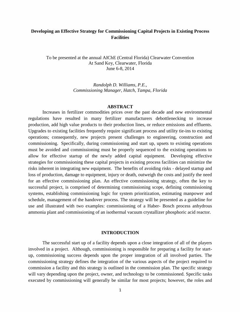
1 Developing an Effective Strategy for Commissioning Capital Projects in Existing Process Facilities To be presented at the annual AIChE (Central Florida) Clearwater Convention At Sand Key, Clearwater, Florida June 6-8, 2014 Randolph D. Williams, P.E., Commissioning Manager, Hatch, Tampa, Florida ABSTRACT Increases in fertilizer commodities prices over the past decade and new environmental regulations have resulted in many fertilizer manufacturers debottlenecking to increase production, add high value products to their production lines, or reduce emissions and effluents. Upgrades to existing facilities frequently require significant process and utility tie-ins to existing operations; consequently, new projects present challenges to engineering, construction and commissioning. Specifically, during commissioning and start up, upsets to existing operations must be avoided and commissioning must be properly sequenced to the existing operations to allow for effective startup of the newly added capital equipment. Developing effective strategies for commissioning these capital projects in existing process facilities can minimize the risks inherent in integrating new equipment. The benefits of avoiding risks - delayed startup and loss of production, damage to equipment, injury or death, outweigh the costs and justify the need for an effective commissioning plan. An effective commissioning strategy, often the key to successful project, is comprised of determining commissioning scope, defining commissioning systems, establishing commissioning logic for system prioritization, estimating manpower and schedule, management of the handover process. The strategy will be presented as a guideline for use and illustrated with two examples: commissioning of a Haber- Bosch process anhydrous ammonia plant and commissioning of an isothermal vacuum crystallizer phosphoric acid reactor. INTRODUCTION The successful start up of a facility depends upon a close integration of all of the players involved in a project. Although, commissioning is responsible for preparing a facility for start- up, commissioning success depends upon the proper integration of all involved parties. The commissioning strategy defines the integration of the various aspects of the project required to commission a facility and this strategy is outlined in the commission plan. The specific strategy will vary depending upon the project, owner, and technology to be commissioned. Specific tasks executed by commissioning will generally be similar for most projects; however, the roles and
Transcript of Developing an Effective Strategy for Commissioning Capital Projects...
1
Developing an Effective Strategy for Commissioning Capital Projects in Existing Process
Facilities
To be presented at the annual AIChE (Central Florida) Clearwater Convention
At Sand Key, Clearwater, Florida
June 6-8, 2014
Randolph D. Williams, P.E.,
Commissioning Manager, Hatch, Tampa, Florida
ABSTRACT
Increases in fertilizer commodities prices over the past decade and new environmental
regulations have resulted in many fertilizer manufacturers debottlenecking to increase
production, add high value products to their production lines, or reduce emissions and effluents.
Upgrades to existing facilities frequently require significant process and utility tie-ins to existing
operations; consequently, new projects present challenges to engineering, construction and
commissioning. Specifically, during commissioning and start up, upsets to existing operations
must be avoided and commissioning must be properly sequenced to the existing operations to
allow for effective startup of the newly added capital equipment. Developing effective
strategies for commissioning these capital projects in existing process facilities can minimize the
risks inherent in integrating new equipment. The benefits of avoiding risks - delayed startup and
loss of production, damage to equipment, injury or death, outweigh the costs and justify the need
for an effective commissioning plan. An effective commissioning strategy, often the key to
successful project, is comprised of determining commissioning scope, defining commissioning
systems, establishing commissioning logic for system prioritization, estimating manpower and
schedule, management of the handover process. The strategy will be presented as a guideline for
use and illustrated with two examples: commissioning of a Haber- Bosch process anhydrous
ammonia plant and commissioning of an isothermal vacuum crystallizer phosphoric acid reactor.
INTRODUCTION
The successful start up of a facility depends upon a close integration of all of the players
involved in a project. Although, commissioning is responsible for preparing a facility for start-
up, commissioning success depends upon the proper integration of all involved parties. The
commissioning strategy defines the integration of the various aspects of the project required to
commission a facility and this strategy is outlined in the commission plan. The specific strategy
will vary depending upon the project, owner, and technology to be commissioned. Specific tasks
executed by commissioning will generally be similar for most projects; however, the roles and

2
responsibilities for these activities and the interaction between the owner, contractors, vendors,
and project personnel form the strategy. The strategy is identified in the commissioning plan.
IDENTIFY SCOPE AND OBJECTIVES
The objective of commissioning is to deliver a process (facility and equipment) to the
owner operations group that performs according to the design intent. This design intent should
have already been established by the designer, equipment supplier, and the operations group,
prior to commissioning involvement. Commissioning prepares the process to be in a ready for
start up (RFSU) state, and ensures that the process is in compliance with a set of standards before
the facility or equipment can be declared as RFSU. The scope is typically developed from a set
of piping and instrumentation diagrams (P&IDs) and other design documents which detail the
design of the facility. These documents, developed by the project team, are typically mechanical
equipment lists, piping line lists, instrument lists, motor and electrical equipment lists, loop
drawings, motor schematics, one line drawings, and P&IDs. From the scope of work the roles
and responsibilities can be agreed upon by the parties involved.
ROLES AND RESPONSIBILITIES
There are four main groups of personnel that will implement the project strategy. The
four groups are the design team, construction team, commissioning team, and operations team.
Often the operations team is the owner who has contracted the designer or project team. The
design team is tasked by the owner or operating facility to meet the design intent. The design
intent may be improving an existing production line, designing a new facility, meeting
environmental and safety compliances, or preparing an existing facility for turnarounds. The
operations team typically contracts the designer or their in house design department to develop
the project. The construction team is responsible for the building of the equipment and facility.
The commissioning group will be responsible for checking out the construction build and
ensuring the process meets the design intent. The operations team is responsible for the
continuous running of the process, and may or may not be responsible for the initial start up or
performance guarantee of the process. The owner may determine who will comprise the
commissioning team and the operations team. Often, the owner, being familiar with operating
procedures, will be part of the commissioning team. This involvement will help to facilitate a
smooth transfer of equipment from commissioning to operations, as often times operations will
be called upon to witness commissioning activities. Operations involvement in commissioning
is, of course, dependent upon the already established scope of work and method for executing the
project.

3
Since much of the commissioning work involves validating the design, construction and
installation, the construction team should never be in charge of the commissioning effort. It is an
effective strategy, although not essential, to include the designers as part of the commissioning
team since these personnel with be thoroughly familiar with the design intent, the project scope
and project history. Nevertheless, the commissioning team involvement should be an unbiased
assessment of the process, equipment, or facility with the already stated objective of declaring a
process as RFSU. The commissioning team objective is not to assign fault to the project,
designer, owner or contractor, but rather to ensure that equipment will function safely and as
designed. This responsibility has inherent risks that may or may not be mitigated by the
operations team based on their acceptance of the process facilities from the commissioning team.
For example, operations may be advised of the risks associated with starting up a piece of
equipment as a consequence of not completing necessary commissioning checks on the new
process or equipment. Commissioning must always present the outcome of all recommended
testing and advice upon RFSU or RFSU with exceptions, if necessary. The status of RFSU will
ensure that the operations team is fully aware of the state that a facility or equipment is being
handed over for start up. From this discussion, it is clear that an effective commissioning
strategy must then be one that ensures all procedures and practices between the designer,
construction team, contractors and operations are aligned. These aligned practices will define
the construction completion sequence and/or schedule, the sequence for handover to pre-
commissioning and commissioning, and the handover to operations. The practices are agreed
upon by the owner/operations team and identified in the commissioning plan. A typical
definition of the tasks and responsibilities for each team and some common tasks associated with
each team is shown in Table 1. The names assigned to these stages may be different depending
upon the project – it is more important that the roles are identified and agreed upon by all
contractually involved and as early as possible in the project. Once each group completes its
responsibilities, a milestone is achieved. The basic milestones are defined as the construction
completion certificate (or mechanical completion) and the commissioning completion certificate.
The responsible group/team certifies that the responsibilities are completed within their scope
and their work is properly documented. The team that accepts the work from the previous party,
verifies that the work is completed satisfactorily and accepts responsibility for the newly
transferred equipment/facility until their responsibilities are complete. The final acceptance of
the project will typically be by the operations plant manager and or owner project manager from
commissioning to operations.
Table 1 indentifies specific stages in the project where a team takes control over areas or
systems. These stages of transfer of care and custody are defined as handover. At each handover
there are inspections to ensure that the system is complete. The care and custody transfer of areas
is important in both new and existing facilities. In existing facilities, the owner may transfer
equipment from operations to construction for debottlenecking or turnaround projects. The
owner cannot operate equipment in the areas that have been transferred to the construction
group. Likewise, once equipment has been handed over from construction to commissioning,

4
construction cannot work on the equipment that has been handed over to commissioning without
permission from commissioning. This is necessary to ensure that equipment is not re-
contaminated or the integrity of a commissioned system is not compromised. More importantly,
handovers are necessary to ensure the safety of personnel working in the construction or
operating areas.
Table 1. Roles and responsibilities, with handover defined
Construction Pre-Commissioning / Commissioning Operations Production
Installation Energize Instrument
calibration
Introduce process
gas
Sustained production
Inspections Motor rotation bump
tests
Loop tests Heat up
Air/Steam
Performance Check
Alignment Equipment tests
/Adjustments
Control and
interlock check
Start up / Ramp
up
I/O checks Flushing/Cleaning/
Lubrication
Equipment
configuration
Loop tuning
Handover to
Commissioning
Leak tests Catalyst Loading Catalyst
Reduction
Equipment checks Plant Purging/Leak
test
Handover to
Operations
Prime Responsibilities
Construction
Manager
Commissioning
Manager
Commissioning
Manager
Operations
Manager
Operations Manager
Support Responsibilities
Contractors Contractors Contractors Commissioning
Team
Commissioning
Team
Equipment Vendors Equipment Vendors Equipment Vendors Equipment
Vendors
Equipment Vendors
Engineering
Support Team
Engineering Design
Support Team
Engineering Support
Team
Engineering
Support Team
Engineering Support
Team
Operations Operations
SYSTEMIZATION AND PRIORITIZATION
Systemization is the identification of boundaries between process equipment and piping.
Electrical and control equipment may also be systemized. The system boundaries are identified
by “marking up” design documents such as P&IDs, single line diagrams, and control schematics.
The purpose of systemization is to:
Clearly identify boundaries between two or more systems for safety isolation
Identify a group of related equipment that collectively form a function for pre-commissioning
and commissioning testing
To facilitate an effective handover of areas from construction to commissioning
To identify meaningful boundaries to drive start up.

5
The identification of systems is also based upon the operations group requirements for
start up. The operations group requirements for systems are typically process driven; however,
the construction group typically completes the build by areas. Consequently, commissioning
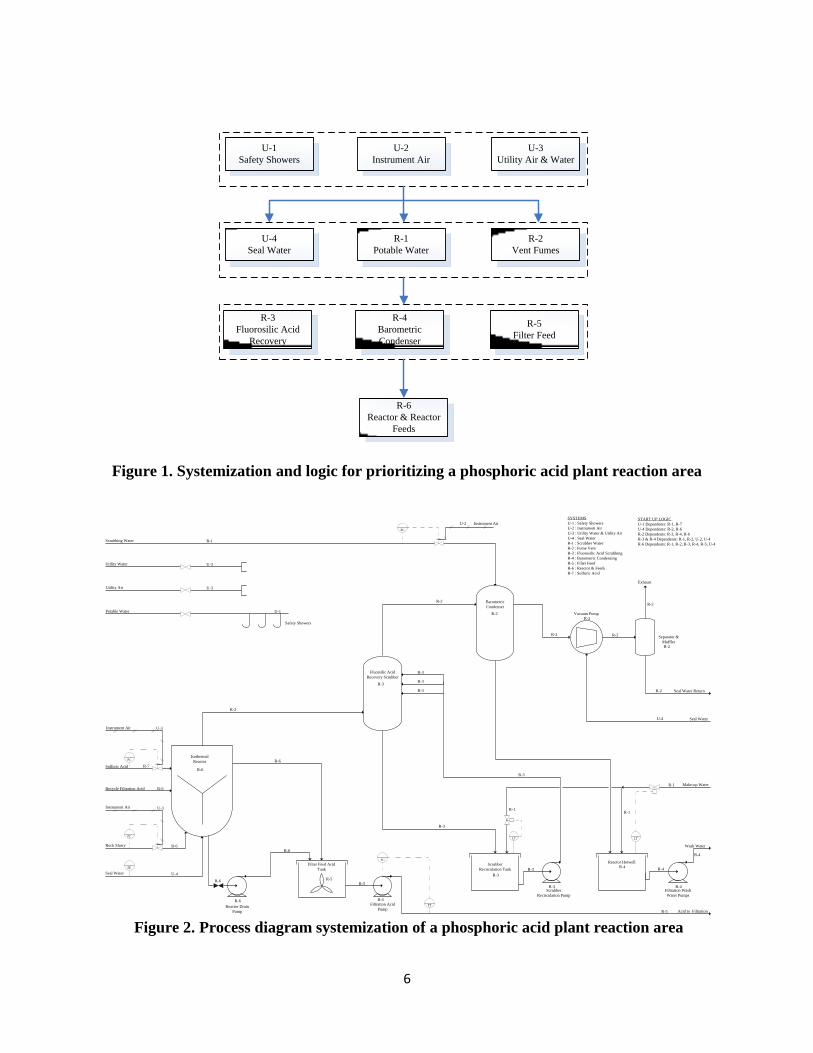
systemization must also try to accommodate area completion as much as possible. Examples of
systemization are show in Figure 1 for a Haber-Bosch ammonia production facility and Figure 3
for a phosphoric acid plant isothermal reaction process. The operations group requirements can
be determined through a review of the standard operating procedures. In debottlenecking of
existing facilities, the operating plant determines the availability of utility and process systems
for commissioning. The successful identification of commissioning systems will then identify
process systems based upon the piping and equipment tie-ins to the existing facilities and when
these tie-ins can be completed.
Once the system boundaries are identified, the systems are given names or tags for
identification purposes. These tags are transferred to design documents such as process flow
diagrams, P&IDs, control architecture, piping line lists, motor and electrical equipment lists,
mechanical equipment lists and instrument lists. A review of the equipment manuals and other
design documents is then used to determine which pre-commissioning testing and
commissioning testing is required for each system as shown in Table 2 for the ammonia plant. In
Table 2, the ammonia plant is first segregated into a front end (equipment from the methane gas
feed to the high temperature shift converter) and back end (downstream of the high temperature
shift converter). Within each of the front end and the back end, process systems are identified.
The next step is to determine how to prioritize the systems for start up. To determine
commissioning priority, the complexity of the equipment or process system is considered. For
example problems with equipment such as process air compressors, refrigeration compressors,
and the synthesis gas compressors (in the ammonia plant) may require significant time to correct
(1). In general, however, systems are prioritized in order to complete in the order below:
1. Safety first
2. Electrical second
3. Controls third
4. Process utilities fourth
5. Process systems
This order of prioritization is shown in Figure 1. The logical systems are identified with tags
(U-1 to U-4 and R-1 to R-7) as shown in Figure 1 and Figure 2. The start of the isothermal
reactor system R-6 depends upon the commissioning of the seal water to pumps and other
equipment seals (U-4), scrubbing water (R-1), equipment ventilation and vacuum (R-2),
scrubbing and condensing of effluent gases (R-3 and R-4), and a hold point for overflow from
the reactor (R-5). Other system startup dependencies are shown under “Startup Logic” in Figure
2. Material handling facilities are prioritized in the order of the start up or shut down sequences
for groups of equipment. Isolation boundaries for material handling facilities, where isolation
6
U-1
Safety Showers
U-2
Instrument Air
U-3
Utility Air & Water
U-4
Seal Water
R-1
Potable Water
R-2
Vent Fumes
R-3
Fluorosilic Acid
Recovery
R-4
Barometric
Condenser
R-5
Filter Feed
R-6
Reactor & Reactor
Feeds
Figure 1. Systemization and logic for prioritizing a phosphoric acid plant reaction area
FC
FC
FE
FC
LT LT
SC
FT
Isothermal
Reactor
Fluorsilic Acid
Recovery Scrubber
Filter Feed Acid
Tank
Barometric
Condenser
Safety Showers
Reactor Drain
Pump
Filtration Acid
Pump
Scrubber
Recirculation Tank
Reactor Hotwell
Filtration Wash
Water Pumps
Scrubber
Recirculation Pump
Vacuum Pump
Separator &
Muffler
Scrubbing Water
Utility Water
Utility Air
Potable Water
Exhaust
Seal Water Return
Seal Water
Make-up Water
Wash Water
Acid to Filtration
Instrument Air
Instrument Air
Instrument Air
Rock Slurry
Seal Water
Sulfuric Acid
Recycle Filtration Acid
U-3
U-3
U-1
U-3
U-3
R-7
R-6
R-6
U-4
R-6
R-6
R-2
R-1
R-6
R-6
R-5
R-6
R-3
R-2
R-2
R-2
R-2
R-2
R-2
R-2
R-2
U-4
R-1
R-4R-4
R-4
R-4R-3
R-3
R-3
R-3
R-3
R-3
R-3
R-3
R-5
R-5
R-5
R-1R-1
U-2
SYSTEMS
U-1 : Safety Showers
U-2 : Instrument Air
U-3 : Utility Water & Utility Air
U-4 : Seal Water
R-1 : Scrubber Water
R-2 : Fume Vent
R-3 : Fluorosilic Acid Scrubbing
R-4 : Barometric Condensing
R-5 : Filter Feed
R-6 : Reactor & Feeds
R-7 : Sulfuric Acid
START UP LOGIC
U-1 Dependents: R-1, R-7
U-4 Dependents: R-2, R-6
R-2 Dependents: R-3, R-4, R-6
R-3 & R-4 Dependents: R-1, R-2, U-2, U-4
R-6 Dependents: R-1, R-2, R-3, R-4, R-5, U-4
Figure 2. Process diagram systemization of a phosphoric acid plant reaction area

7
Figure 3. Systemization and logic for prioritization of an ammonia production facility
13 kV Substation
Transformer
Motor Control
Centers
Un-interrupted
Power SupplyControl Systems
Cooling Water
Potable Water
Instrument Air
Deaerator & Boiler
Feed Water
Feed Gas
Pre-Treatment
Fuel Gas
Front End Vent
Nitrogen
SynGas Generation
Temporary Boiler
Steam
Steam Condensate
Process Condensate
Process Air
Compressor Turbine
Lube Oil Flush
Process Air
Compressor Turbine
Overspeed Trip
Absorber/Scrubbing
Systems
SynGas Purification
Front End Start Up & Reductions
SynGas Loop
Ammonia
Refrigeration
Purge Gas Recovery
Ammonia
Absorption & Flare
Ammonia Storage
Back End Start
Up &
Reductions
Tune & Ramp Up
Production
Performance
Testing
First Ammonia
Production
SynGas Compressor
Turbine Lube Oil
Flush & Overspeed
Trip
Ammonia
Compressor Turbine
Lube Oil Flush &
Overspeed Trip

8
Table 2. Systems and commissioning activities for startup of an ammonia facility
Start up Step System Required Commissioning Activity
Leak Test Front End Front End up to High
Temperature Shift (HTS) Leak check
Fire Auxiliary Boiler Instrument Air Chemical clean, motor run
Fuel Gas Blow and leak check
Nitrogen Blow and leak check
City Water Safety showers tested
Cooling Water Flush, turbine overspeed trip (OS)
Primary Reformer Fan lube oil flush / test fire burners
Boiler Feed Water (BFW) Chemical clean / turbine OS trip
BFW Chemical Treatment Leak check tubing
Steam (All Levels) Steam blow
Condensate Steam blow
Produce Steam for High Pressure Blow - Steam blow
High Pressure Steam at Start-up
Run Process Air Compressor Turbine Process Air Compression Air compressor turbine OS trip
Surface Condenser Condenser pump motor run
Reformer and HTS Heat up - -
Introduce Process Steam Primary Tubes Feed Gas Treatment -
Preheat Desulfurizers - Load ZnO drum
Introduce Natural Gas Feed - -
Reduce Primary & Secondary Reformer
Catalyst - -
Heat HTS with Medium Pressure Steam
Shift Conversion and
Methanation Air blow, load catalyst
Transfer Vent Downstream of HTS/Reduction - -
Move Venting to Absorber Inlet Absorber Vent -
Establish Absorber System Operating CO2 Removal Chemical clean
Transfer Vent Downstream of Absorber Process Condensate Stripping Flush
Stabilized CO2 Removal Operation
- - Move Vent to Syn Gas Suction Drum/
Methanation Reduction
Perform LTS Reduction - Catalyst loading
Refrigeration Compressor - Establish
Refrigeration Loop Conditions Refrigeration Compression Leak test, purge
Pressure Syn Loop with Front End Gas Syn Loop Leak test, purge
Syn Gas Machine Start up -Establish
Circulation Loop Syn Gas Compression Leak test, purge
Test Fire Start up Heater Burners Start up Heater Blow, leak test
Heat Converter using Start up Heater - Leak test, purge
Start Converter Catalyst Reduction (First
Ammonia Production) - -
Ready Ammonia System Ammonia Export and Storage Leak test, purge
Purge Gas Recovery Air blow, leak test, purge
Inventory Refrigeration System with
Ammonia
Process Flare Leak test
Refrigeration Leak test, purge

9
valves not likely to be part of the design, can be identified where there is volume storage, such as
storage silos, hoppers, or bins. The effective identification and prioritization of systems is the
key to an effective commissioning and start up.
COST, MANPOWER AND SCHEDULE
Table 3 shows a summary of statistics on start up costs and durations (5). Data in Table 3
was compiled from a review of the start up of up to 53 plants. From the data reported, pre-
commissioning and commissioning cost can be initially estimated as a total of 5 percent of the
capital cost of a project (5).
Table 3. Start up cost and durations
Measure
Mean
Median
Standard
Deviation
Range
Number
of Plants
Months of
Startup
8.0
4.0
8.9
0-30
53
Startup Costs
as % of Capital
Through Construction
5.5
3.6
6.1
0-20
51
When the scope of the project and the scope of the commissioning services are finalized,
a more detailed estimate of commissioning cost can be determined. Methods for determining
detailed estimates of commissioning manpower have already been developed (2). Table 4
provides a preliminary estimate of commissioning cost based solely upon manhours to complete
pre-commissioning and commissioning testing activities. Estimates for commissioning, based on
Table 4, show that the project commissioning cost can be largely due to one of two types of
commissioning categories:
A highly automated design facility that is reliant upon electrically driven/actuated
equipment
Or a facility that is more complex in the chemical process design.
Table 4 can be used to determine the manpower required in each commissioning discipline. The
example in Table 4 is based upon an assumed seven month commissioning duration.
The minimum permanent members of the commissioning team should be a
commissioning manager, a programmer, a mechanical discipline engineer or technician, an
electrical discipline engineer or technician, a safety officer (responsible for maintaining lock out
tag out, permits, and authorization for energization) and an instrumentation engineer or
technician. On complex process driven projects, it may also be beneficial to include a piping
designer or piping engineer. Other areas that require expertise during commissioning can be
called upon as required (1). An example organization chart is shown in Figure 4.

10
The commissioning schedule can be developed from the commissioning systems and the
estimates in Table 4. This schedule can then be used to determine the commissioning cost. The
commissioning schedule is developed in conjunction with the construction team as early as
possible. This early schedule will take into consideration the initial estimated duration for each
system, construction contract schedules, and construction progress. The schedule will forecast
the commissioning to operations handover dates for each system. The schedule durations and
manpower is further refined when specific commissioning procedures and resource loading are
developed.
Table 4. Pre-commissioning manhours estimation example
Electrical, Instrumentation and Process Controls
Equipment Count
IO per
Unit
Total
IO
Hours
per IO /
Item Total Hours Discipline
Motors 50 5 250 2 500 Electrical
Variable Speed Drives 20 7 140 2 280 Electrical
Instruments Analog 100 1 100 3 300 Controls
Instruments Digital 200 1 200 2 400 Controls
Interlocks 50 - - 5 250 Controls / Process
Interlock Integration 50 - - 5 250 Controls / Process
Administration - - - - 1485 (75% of Total Hours)
Electrical & Controls Total - - 690 - 3465
Schedule Duration 1750
(Based upon a 7 month duration)
Manpower Required 1.98
Electrical and Controls Personnel Required
Mechanical and Piping
Pumps 40 - - 6 240 Mechanical / Process
Fans 10 - - 10 100 Mechanical / Process
Vessels & Tanks 30 - - 2 60 Mechanical / Process
Piping - Utilities 50 - - 3 150 Piping
Piping - Process Liquid 300 - - 5 1500 Piping
Piping - Process Gas 100 - - 5 500 Piping
Couple/Alignment 50 - - 5 250 Mechanical
Run Test 50 - - 5 250 Mechanical / Process
Administration - - - - 2288 (75% of Total Hours)
Mechanical & Piping Total - - - - 5338
Project Total Hours 8803
Schedule Duration 1750 (Based upon a 7 month duration)
Manpower Required 3.05 Mechanical and Piping Personnel Required

11
Owner Project
Manager
Designer Project
Manager
Commissioning
Manager
Commissioning
Engineers
Electrical
Instrumentation
Mechanical
Programmer/Process
Controls
Equipment Vendors
Commissioning
Skilled Laborers
Millwrights
Pipefitters
Riggers
Electrical/
Instrumentation
Technicians
Commissioning
Support
Construction
Manager
Construction Management Team
Electrical/ Instrumentation
Superintendant
Mechanical Superintendant
Project Controls
Project Engineer
Safety Manager
Quality Assurance Manager
Quality Control Inspector
Electrical Contractor
Construction Manager
Electrical
Quality Assurance/
Control Manager
Construction Electrical/
Instrumentation
Technicians
Mechanical Contractor
Construction Manager
Mechanical
Quality Assurance/
Control Manager
Construction Skilled
Laborers
Millwrights
Pipefitters
Riggers
Owner Commissioning
Manager/Operations Manager/
Plant Manager
Operators
Maintenance
Manager
Rotating Equipment
Specialist
Vibration Analysis
Mechanical Alignment
Millwrights
Electrical/
Instrumentation
Manager
Electrical/
Instrumentation
Support Technicians
Figure 4. Organization chart
PUNCHLISTING: A MEANS TO CONTROL SYSTEM HANDOVER
A deficiency list or punchlist is a list of items that serve as a verification of the
construction build, an inspection of the quality of the build, and the operability and safety of a
system. The deficiency list is written up from a thorough review of each commissioning system
and formally issued to contractors for rectification. The punchlist is not simply a visual
inspection of the build; it is a line by line, equipment by equipment check using the P&IDs and
other design documents to determine what rectifications are required to ensure the safe
commissioning of that system. It has been reported that 61 percent of start up problems were
related to equipment deficiencies, 10 percent due to design inadequacies, 16 percent due to
construction deficiencies, and 13 percent due to human error (5). In another study of 53 plants a
total of 30 plants reported failures due to equipment and or equipment and design failures (5).
Therefore, potentially 50 to 97 percent of deficiencies can be identified and rectified through
punchlisting.
The commissioning team manages the process for developing and maintaining the
deficiency list. An example of a process for punchlisting is depicted in Figure 5. The process
begins with all parties agreeing upon the categorization of priorities for rectification of

12
deficiencies. The example process for punchlisting, shown in Figure 5, may vary. The
involvement of the owner in this process may vary depending upon the project; the process is
agreed upon by all parties during the formation of the commissioning strategy. It is
recommended, however, that construction produce its own internal punchlist. Based upon the
status of construction deficiencies, construction shout notify commissioning when a system is
ready for commissioning to punchlist.
Typically commissioning will begin inspection of construction progress at approximately
80% construction completion (1). The percentage of construction completion can be determined
from the overall schedule construction completion status. The commissioning punchlisting can
also serve as a verification of construction status as reported in the schedule. Since
commissioning begins inspection at 80% construction completion, commissioning is fully
cognizant that there will be deficiencies in the systems. The purpose of punchlisting prior to
100% construction completion is to work alongside construction, not after. This strategy also
ensures that potential pitfalls that may require rework of equipment or piping is avoided. For
instance, relocating piping as identified in a commissioning deficiency list, prior to completing
piping stress analysis and prior to hydrotesting, will be advantageous to the overall project
budget and schedule. From the punchlist process shown in Figure 5, priority 1 is defined as
deficiencies to rectify to ensure safe/reliable pre-commissioning; priority 2 is defined as
deficiencies to rectify to ensure safe/reliable commissioning; and priority 3 is defined as
deficiencies to rectify to complete prior to handover to operations for start up. Examples of
punchlist findings, which demonstrate the value of punchlisting, are depicted in Figure 6.
Figure 5. Punchlisting process

13
Figure 6. Deficiencies identified during punchlisting
Deficiencies shown in Figure 6 are listed below:
A. Loose hold down bolts on a vibrating feeder motor
B. Incorrect spray nozzle orientation in a fluorine recovery ductwork
C. Shipping brackets not removed in a weight belt feeder
D. Nozzle projection on a radar level transmitter is longer than the radar cone
E. Longer than designed dip pipe distance from hotwell floor
F. Butterfly valve difficult to operate due to pinching with rubber lined pipe spool
G. Valve handle is a pinch point with grating
H. Broken off leads on gas heater potentiometer
I. Ground wire hanging inside a sump, wire should be terminated to sump metal cover
If the deficiency list items are properly categorized, the completion of punchlist items by
priority becomes the source for determining whether a system can advance from one handover
stage to the next. The authorization to safely introduce hazardous process fluids into a system is
determined when all priority punchlist items are rectified. The responsible parties should not

14
sign handover from one stage to another without verification that the punchlist items are
rectified. The final handover from commissioning to operations can be accomplished when all
priority items required for start up are completed. Since the punchlist can prevent the acceptance
of system handover at any stage, the punchlist is the most critical documentation in the
commissioning system documents.
RISK AND CONTINGENCY
The value of commissioning is realized through the reduced life cycle costs and increased
reliability of the commissioned assets. The investment in commissioning is at the discretion of
the owner and the owner’s acceptance of risk. It may not be feasible or economical to test all
scenarios and circumstances during commissioning; however, not testing everything and having
an asset fail, may be a greater risk. This is where experience and commissioning expertise can
make valued input to projects and make recommendations for what are essential commissioning
testing requirements to declare a commissioning system as ready for start up. Commissioning
can identify the major risks during pre-commissioning, system handover to commissioning,
commissioning and handover to operations. Commissioning can then determine preventative
steps, contingency plans and monitoring for credible and significant risks. At a minimum,
commissioning considers risks as construction handover delay, insufficient personnel
knowledge, potential for high overtime, non-availability of critical utilities, non-availability of
parts, production of off specification product or byproducts, or transient operating conditions
during commissioning. Additionally, methods are available for evaluating these risks using
failure modes and effects analysis, risk ranking, and comparing the actual commissioning cost to
the failure modes (3).
CONCLUSION
The successful commissioning depends upon many factors. Some of these factors have
been identified in this paper as items to include in an effective commissioning strategy. In
summary critical factors for an effective commissioning strategy are:
Early integration of operations personnel in commissioning
Properly identifying and staffing commissioning roles/teams
A quality design as verified by the detailed pre-commissioning checks and
deficiency lists
Early start up planning, properly managing the handover process, identifying
scheduling and cost
Wwell developed commissioning procedures and plans
Proper and detailed commissioning documentation
Proper systemization and prioritizing of the facilities or assets
Alignment of the commissioning scope and objectives with the owner and project
teams.
15
REFERENCES
1. Mukherjee, Siddhartha (2005), “Preparations for Initial Startup of a Process Unit,”
Chemical Engineering, pp. 36-42.
2. Bailey, Barry, “Commissioning – The Interface Between Construction and Operations,”
in First Extractive Metallurgy Operators’ Conference, Brisbane, Queensland, Australia,
November 7-8, 2005.
3. Venters, David G., et. al, “Rolling the Dice: Using Risk Tolerance to Define
Commissioning Scope,” in National Conference on Building Commissioning, April 19-
21, 2006.
4. Lager, Thomas, “Startup of new plants and process technology in the process industries:
organizing for an extreme event,” Journal of Business Chemistry, February, 2012.
5. Myers, Christopher and Ralph F. Shangraw, Understand Process Plant Schedule
Slippage and Startup Costs, Santa Monica, California, Rand, 1986, pp. 31-53.
6. Kris Lawry and Dirk John Pons, “Integrative Approach to the Plant Commissioning
Process,” Journal of Industrial Engineering, vol. 2013, Article ID 572072, 12 pages,
2013.
ACKNOWLEGEMENT
I would like to thank Martin Killcross (Sasol), George Colman (KBR), Bob Skorcz (J. R.
Simplot), Mel Weber (PotashCorp) and Joel Rivers (Potash Corp).