
Developement of System Design Code for Heliotron...
22
Developement of System Design Code for Heliotron Reactors Takuya GOTO , Akio SAGARA and Shinsaku IMAGAWA National Institute for Fusion Science Japan-US Workshop on Fusion Power Plants and Related Advanced Technologies with participation of China 16-18 th March, 2009 Kashiwa Campus, The University of Tokyo
Transcript of Developement of System Design Code for Heliotron...

Developement of System Design Code
for Heliotron Reactors
Takuya GOTO, Akio SAGARA and Shinsaku IMAGAWA
National Institute for Fusion Science
Japan-US Workshop on
Fusion Power Plants and Related Advanced Technologies
with participation of China
16-18th March, 2009 Kashiwa Campus, The University of Tokyo

Japan-US WS on Fusion Power Plants and Related Advanced Technologies
16-18th March 2009, Kashiwa Campus, The Univ. of Tokyo2/19
Outline
1. Introduction
2. Required performance of system code
3. Consideration of simplified calculation method
– Approximation formula
– Inter/extrapolation
4. Summary and future work
Japan-US WS on Fusion Power Plants and Related Advanced Technologies
16-18th March 2009, Kashiwa Campus, The Univ. of Tokyo3/19
1. Introduction
• Heliotron reactors inherently has suitable properties as a commercial plant
– Free from any operational restriction caused by a plasma current(e.g., possibility of high density operation � low divertor heat load)
– No need of current drive power (low recirculation power � high plant efficiency)
• LHD has achieved good plasma properties:
– High averaged beta <β>=5.1%– High density ne(0)=1.2×10²¹m-3 (SDC-IDB)
• The design study of FFHR has progressed
• We have a perspective of designing a heliotron power plant

Japan-US WS on Fusion Power Plants and Related Advanced Technologies
16-18th March 2009, Kashiwa Campus, The Univ. of Tokyo4/19
• Oft-expressed disadvantages of heliotron system:
– Narrow Space between coil and plasma
– Low confinement due to non-axisymmetric property
– Difficulties in design and construction
Introduction(cont’d)
� Can be compensated by selecting adequate design
point (e.g., FFHR-2m2: enlarging plasma size
compatible with a moderate construction cost)
� LHD was successfully constructed and has been in
operation for over 10 years
Numerical/engineering technology has been progressed

Japan-US WS on Fusion Power Plants and Related Advanced Technologies
16-18th March 2009, Kashiwa Campus, The Univ. of Tokyo5/19
Introduction(cont’d)
• Right now, problems lie in a design study of heliotron system are
– Low number of the existing device and (at present) no existence of an experimental reactor prior to DEMO
– Difficulties in an interpretation of experimental results and prediction of plasma performance (high degree of freedom in design and a requirement of complicated 3D calculation)
• These points lead to low reliability in a prediction of plant performance and difficulty in an optimization of design point.
Japan-US WS on Fusion Power Plants and Related Advanced Technologies
16-18th March 2009, Kashiwa Campus, The Univ. of Tokyo6/19
Purpose of This Study
• For a proposal of a feasible design point, we need to
find a design window with not fully optimized, but
“robust” design points.
• These points should be selected with a consideration
of total system design.
• Sensitivity analyses over a wide design space are
needed.
�Attempted to develop a system design code

Japan-US WS on Fusion Power Plants and Related Advanced Technologies
16-18th March 2009, Kashiwa Campus, The Univ. of Tokyo7/19
2. Required performance of system code
• Assume the use in design window survey through sensitivity analysis.
• Required to calculate core plasma performance, engineering design, plant performance (electric output, cost, amount of rad-waste) simultaneously.
• Whereas, computational time is desired to be as short as possible (cf. computational time of 0.864sec per one parameter set
→100,000 design points in 24 hr
66=46656, 310=59049)

Japan-US WS on Fusion Power Plants and Related Advanced Technologies
16-18th March 2009, Kashiwa Campus, The Univ. of Tokyo8/19
System Code for Tokamak
• Quasi-axisymmetric properties :
allows estimation only on a certain poloidal cross-section
• Simple toroidal magnetic field profile: B(R)=BmaxRin/R
• Externally controllable plasma parameters: a, κ, δ, Ip• Empirical scaling of plasma confinement property supported
by abundant experimental data:
τEIPB98(y,2)=0.0562Ai0.19Ip
0.93Rp1.97ε0.58κ0.78n19
0.41Bt0.15Pall
-0.69
• Fairly good prediction can be obtained by
– 1-D design (radial build) of plasma and surrounding components
– averaged plasma properties along a poloidal cross-section

Japan-US WS on Fusion Power Plants and Related Advanced Technologies
16-18th March 2009, Kashiwa Campus, The Univ. of Tokyo9/19
Issues in System Code for Heliotron
• Magnetic field configuration is automatically determined by the geometry of helical and poloidal coils
�Plasma parameters cannot be given as inputs
• ISS(International Stellarator Scaling) requires plasma parameters averaged over a field period:
Rgeo : (0,0) component of Fourier expansion of LCFS radius
�Need 3D equilibrium calculation
2
2
geo
2 ,2
p
ttpp
aBaRV
ππ
Φ==
∑ −=nm
mn nmRR,
)sin(cos φθ
0.4
2/3
83.051.059.0
tot
65.0
geo
21.2ISS95 079.0 ιτ tepE BnPRa
−=

Japan-US WS on Fusion Power Plants and Related Advanced Technologies
16-18th March 2009, Kashiwa Campus, The Univ. of Tokyo10/19
3. Consideration of Simplified Calculation
• Detailed calculation is needed for the parameters related to helical coil– Maximum field on coil Bmax→Magnetic field on confinement region Bt
(→Confinement performance)
– Coil shape (Rc, ac, m, …)→Magnetic surface configuration (Rgeo, <a>, amin) (→ confinement property, blanket placement)
– Coil shape → Stored magnetic energy Wmag (→ location of poloidal coil)
• They cannot be obtained by simple analytical formulae, but should be described by the geometry of helical coils
→ expected to be continuous functions of coil geometric parameters
• Can be calculated with an approximation formula or inter/extrapolation

Japan-US WS on Fusion Power Plants and Related Advanced Technologies
16-18th March 2009, Kashiwa Campus, The Univ. of Tokyo11/19
The case of LHD optimization
• In the design optimization of LHD, several scaling formulae proposed by Yamazaki[1] were used:
• But these formulae don’t include the effects of– coil cross-sectional shape
– coil pitch modulation
c
ax
a
∆=δ
[1] Kozo Yamazaki et al., Fusion Technology 21 (1992) 147.
51.0
c
17.0
c
05.0
c
42.040.0
0
cc
0
max
3.0
44.09.0
1054.0
,2.1
10
401.2
−−
=
=
δγ
γ
m
a
a
mB
Rj
B
B
p

Japan-US WS on Fusion Power Plants and Related Advanced Technologies
16-18th March 2009, Kashiwa Campus, The Univ. of Tokyo12/19
(α :pitch modulation )• Describe Bmax/<B0> with non-dimensional parameter m,
α, and the parameter which gives maximum field on the infinite-length conductor with rectangular cross-section:
Example of approximation formula
~magnetic field scaling~
• The maximum field on the coil Bmax and
average toroidal field <B0> are the important
parameters in the reactor design.
• The ratio Bmax/<B0> is non-dimensional and
determined only by the coil geometry.
→ expected to be described with the non-
dimensional parameter consisted of the
parameters related to coil configuration Rc, ac,
m, α, Sc, W/H.( ) ( )[ ]φαφθ mm ll sin+=
cc RS≡ζ
( ) ( ) ( ){ }2tan441ln 12 xxxx −++=ξ HWx ≡,
( ),ccc Rma l≡γ

Japan-US WS on Fusion Power Plants and Related Advanced Technologies
16-18th March 2009, Kashiwa Campus, The Univ. of Tokyo13/19
New scaling of magnetic field ratio
( ) 815.0796.00.156
c
853.0117.0
0
max 185.0 −−−+= ζξγα mB
B
8.005.0
c
82.0
05.0
c
42.040.0
0
cc
0
max
2.1
10
401.2 −−∝
= ζγ
γm
mB
Rj
B
B
Yamazaki’s scaling law [1]:
1.007.0
,2.02.0,21
,204),12,10,8( c
≤≤
≤≤−≤≤
≤≤=
ζ
αH
W
Rm
*Presented at 18th TOFE in San Francisco
Japan-US WS on Fusion Power Plants and Related Advanced Technologies
16-18th March 2009, Kashiwa Campus, The Univ. of Tokyo14/19
Calculation of vacuum magnetic field
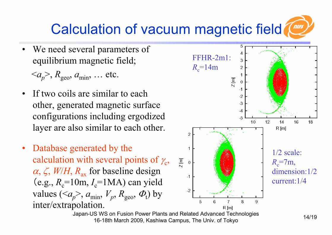
• We need several parameters of
equilibrium magnetic field;
<ap>, Rgeo, amin, … etc.
• If two coils are similar to each
other, generated magnetic surface
configurations including ergodized
layer are also similar to each other.
• Database generated by the
calculation with several points of γc, α, ζ, W/H, Rax for baseline design
(e.g., Rc=10m, Ic=1MA) can yield
values (<ap>, amin, Vp, Rgeo, Φt) by
inter/extrapolation.
FFHR-2m1:
Rc=14m
1/2 scale:
Rc=7m,
dimension:1/2
current:1/4

Japan-US WS on Fusion Power Plants and Related Advanced Technologies
16-18th March 2009, Kashiwa Campus, The Univ. of Tokyo15/19
Effects of poloidal coils
• In the case of LHD, the following 3 conditions were considered to determine poloidal coil currents:– Adjustment of the position of vacuum magnetic
axis Rax
– Adjustment of BQ value (the ratio of cancellation of the quadrapole field generated by helical coils)
– Minimization of a leakage field at R=2.5Rc
(location of NBI system)
• LHD also has discontinuous point in plasma parameters
• For a DEMO/commercial reactor, the use of 2 pairs of poloidal coils has been considered but these location has not yet been fixed.

Japan-US WS on Fusion Power Plants and Related Advanced Technologies
16-18th March 2009, Kashiwa Campus, The Univ. of Tokyo16/19
Placement of poloidal coils
• The structure of equilibrium magnetic field is strongly affected
by location and current of poloidal coils.
Initially proposed
for FFHR-2m2:
RIV / ZOV= 12.8 / 22.1 m
ZIV / ZOV= 6.8 / 4.5 m
IIV / IOV= 14.7 / 17.9 MA
<a>=2.225m, Vp=1570m3
After modification:
RIV / ROV= 12.8 / 22.4 m
ZIV / ZOV= 8.0 / 5.4 m
IIV / IOV= 11.8 / 18.9 MA
<a>=2.465m, Vp=2050m3
Japan-US WS on Fusion Power Plants and Related Advanced Technologies
16-18th March 2009, Kashiwa Campus, The Univ. of Tokyo17/19
Statistical analysis (Wendelstein 7-X)
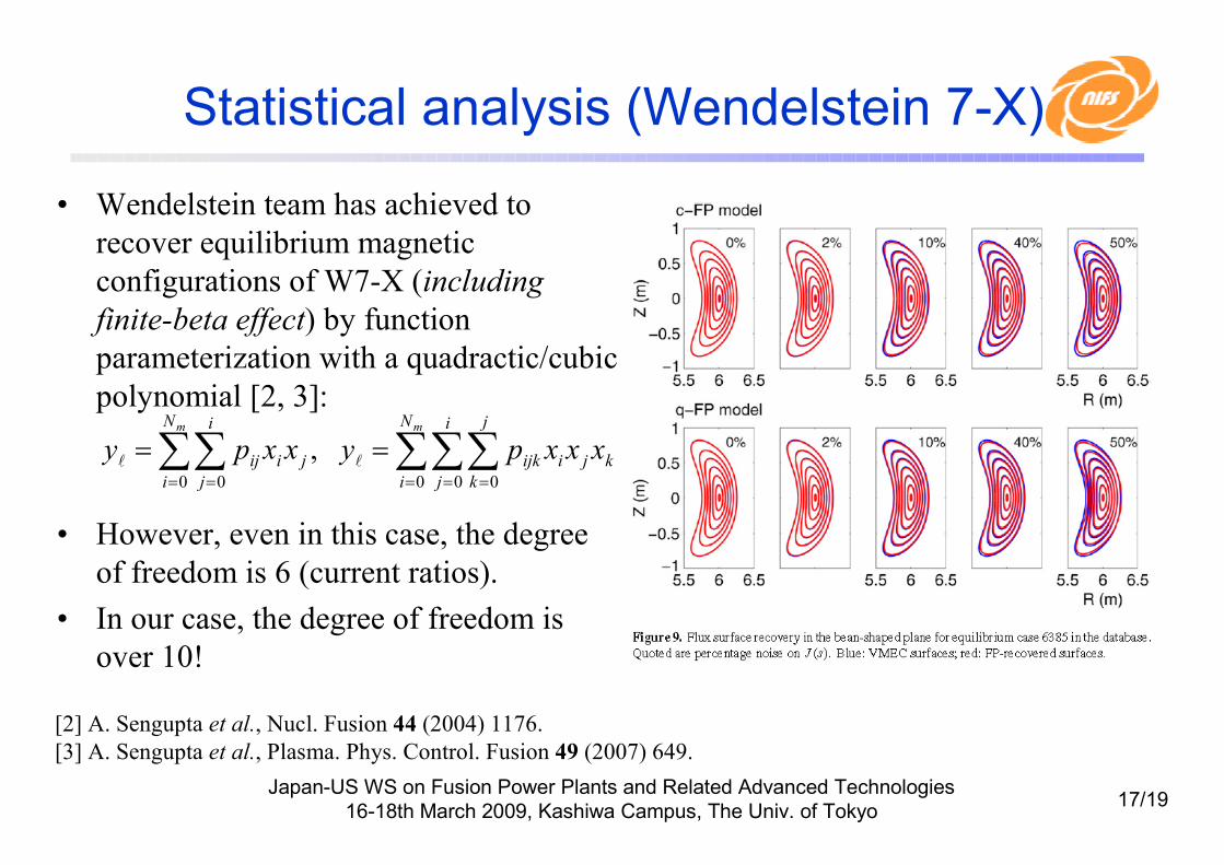
• Wendelstein team has achieved to
recover equilibrium magnetic
configurations of W7-X (including
finite-beta effect) by function
parameterization with a quadractic/cubic
polynomial [2, 3]:
• However, even in this case, the degree
of freedom is 6 (current ratios).
• In our case, the degree of freedom is
over 10!
[2] A. Sengupta et al., Nucl. Fusion 44 (2004) 1176.
[3] A. Sengupta et al., Plasma. Phys. Control. Fusion 49 (2007) 649.
∑∑∑∑∑= = == =
==mm N
i
i
j
j
k
kjiijk
N
i
i
j
jiij xxxpyxxpy0 0 00 0
,ll
Japan-US WS on Fusion Power Plants and Related Advanced Technologies
16-18th March 2009, Kashiwa Campus, The Univ. of Tokyo18/19
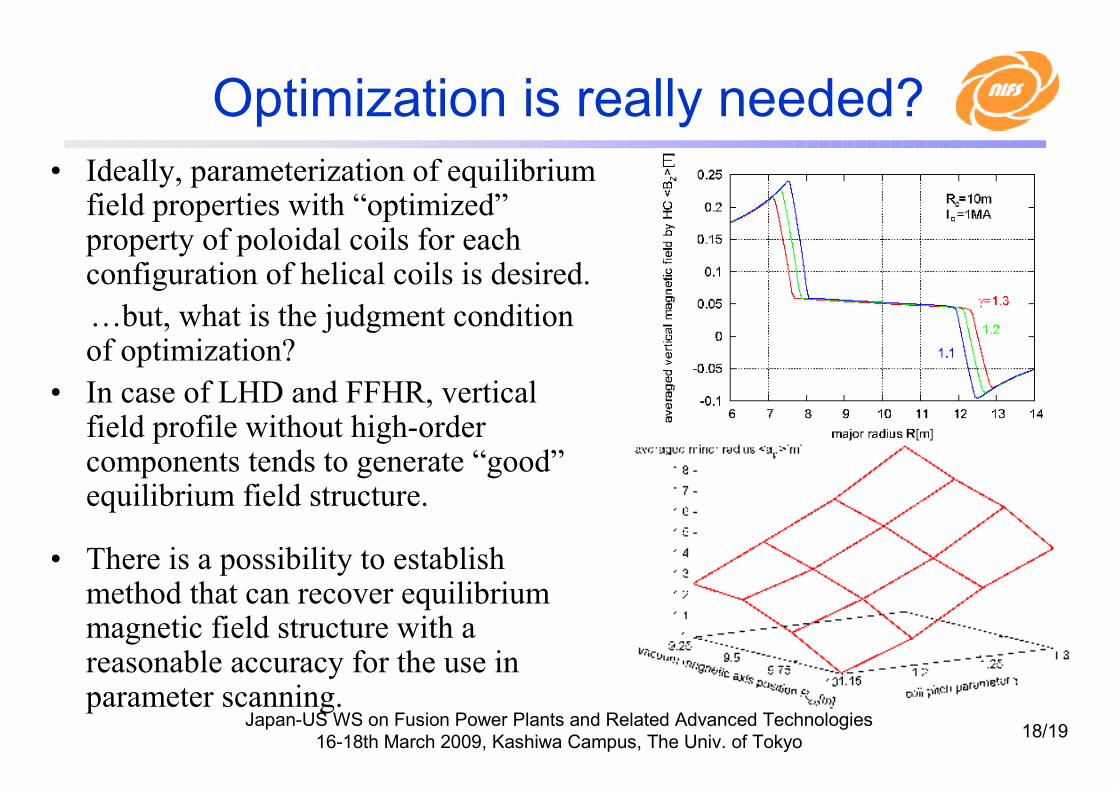
Optimization is really needed?
• Ideally, parameterization of equilibrium field properties with “optimized”property of poloidal coils for each configuration of helical coils is desired.
…but, what is the judgment condition of optimization?
• In case of LHD and FFHR, vertical field profile without high-order components tends to generate “good”equilibrium field structure.
• There is a possibility to establish method that can recover equilibrium magnetic field structure with a reasonable accuracy for the use in parameter scanning.

Japan-US WS on Fusion Power Plants and Related Advanced Technologies
16-18th March 2009, Kashiwa Campus, The Univ. of Tokyo19/19
4.Summary and future work
• System design code for heliotron reactors is being developed. Simplified calculation methods expected to enable sensitivity analyses over a wide design space.
• Immediate issue is to establish a method that can recover equilibrium magnetic field structure with a reasonable accuracy.
• To achieve high reliability, we will need to – improve liability in estimation of plasma performance by
� refining ISS scaling law (considering of dependence on magnetic axis shift and density / temperature profile)
�considering finite β effect
– develop a simple evaluation method for TBR, maintenance, and operation scenario.
• Operation regime with high robustness (that isn’t so much affected by a model ambiguity) is important for assured progress towards a commercial reactor, instead of the (locally) optimized design point.
Japan-US WS on Fusion Power Plants and Related Advanced Technologies
16-18th March 2009, Kashiwa Campus, The Univ. of Tokyo20/19
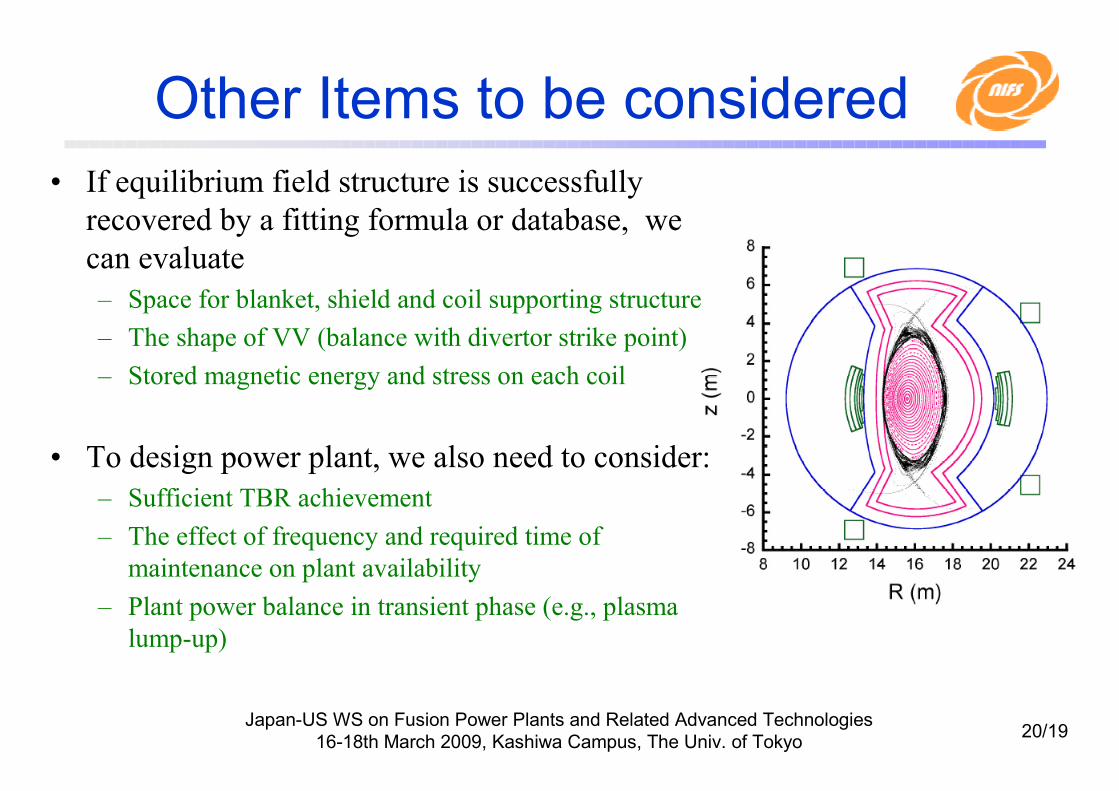
Other Items to be considered
• If equilibrium field structure is successfully
recovered by a fitting formula or database, we
can evaluate
– Space for blanket, shield and coil supporting structure
– The shape of VV (balance with divertor strike point)
– Stored magnetic energy and stress on each coil
• To design power plant, we also need to consider:
– Sufficient TBR achievement
– The effect of frequency and required time of
maintenance on plant availability
– Plant power balance in transient phase (e.g., plasma
lump-up)

Japan-US WS on Fusion Power Plants and Related Advanced Technologies
16-18th March 2009, Kashiwa Campus, The Univ. of Tokyo21/19
Placement of poloidal coils
• The location of poloidal coil (PC) needs to be fixed to carry out equilibrium magnetic surface.
• PC current is determined by dipole component (BD) and quadrupolecomponent (BQ).
• Magnetic field generated by helical coil can be calculated by inter/extrapolation of tabulated data with sufficient accuracy.
-55.150-515.731.2272-0.29960.55116linear
extrapolation
-55.140-515.621.2273-0.29980.55277γc=1.5, ζ=0.06, W/H=2.2
-54.431-508.151.2356-0.32800.58954linear
interpolation
-54.428-508.121.2357-0.32770.58939γc =1.25, ζ=0.15W/H=0.095
Bz(@5Rc)
[Gauss]
Bz(@2.5Rc)
[Gauss]
Bz(R=0)
[T]
BQ
[T/m]
BD
[T]
Table: Magnetic field generated by helical coil with Rc=10m. Ic=1MA

Japan-US WS on Fusion Power Plants and Related Advanced Technologies
16-18th March 2009, Kashiwa Campus, The Univ. of Tokyo22/19
Placement of poloidal coils
• Parameters related to the magnetic field configuration can also
be estimated by inter/extrapolation of tabulated database.
• The volume enclosed by LCFS strongly depends on the PC
current and location. →need further optimization
LHD Rax=3.6mLHD Rax=3.75mLHD Rax=3.9m
Rgeo
Rax
ιa
ι0
<ap>
BD
3.6943.6723.7383.7403.8113.816
3.6513.63.7673.753.9033.9
1.2291.5711.2571.2141.0490.964
0.3060.3780.3340.3490.4020.432
0.5840.6360.5930.5890.5520.535
1.07911.01840.9601
inter-
polation
Calc.inter-
polation
Calc.inter-
polation
Calc.


![Sword Bl 0903[1]](https://static.fdocuments.in/doc/165x107/55d51a67bb61eba1228b465d/sword-bl-09031.jpg)