DEV-i - Bluetechnixdatasheets.bluetechnix.at/goto/DEV-i.MX6x/archive/DEV-i.MX6x_HUM_… · 2.1.14...
39
DEV-i.MX6x Hardware User Manual Version 1.2
Transcript of DEV-i - Bluetechnixdatasheets.bluetechnix.at/goto/DEV-i.MX6x/archive/DEV-i.MX6x_HUM_… · 2.1.14...

DEV-i.MX6x
Hardware User Manual
Version 1.2

Contact
Bluetechnix
Waidhausenstraße 3/19
A-1140 Vienna
AUSTRIA
http://www.bluetechnix.com
Date: 2014-09-22
Template No.: 900-306 / A

Table of Contents
1 Introduction ...................................................................................................................................... 7
1.1 Overview ................................................................................................................................... 7
1.2 Key Features ............................................................................................................................. 7
1.2.1 CM-i.MX6x ......................................................................................................................... 7
1.2.2 Active components on DEV-i.MX6x .................................................................................. 8
1.3 Available extensions.................................................................................................................. 8
1.4 Applications............................................................................................................................... 8
2 General Description ........................................................................................................................ 10
2.1 Functional Description ............................................................................................................ 10
2.1.1 Core Module .................................................................................................................... 10
2.1.2 Power Supply ................................................................................................................... 10
2.1.3 JTAG ................................................................................................................................ 11
2.1.4 TPIU (Trace Port) ............................................................................................................. 11
2.1.5 Extension Connector ....................................................................................................... 11
2.1.1 HDMI ................................................................................................................................ 11
2.1.2 Debug UART .................................................................................................................... 12
2.1.3 USB-OTG ......................................................................................................................... 12
2.1.4 Audio Codec .................................................................................................................... 12
2.1.5 CAN .................................................................................................................................. 13
2.1.6 Ethernet ............................................................................................................................ 13
2.1.7 USB .................................................................................................................................. 14
2.1.8 SD Card ........................................................................................................................... 14
2.1.9 ISM Camera Interface ...................................................................................................... 14
2.1.10 SATA II ............................................................................................................................. 14
2.1.11 PCIe 2.0 ........................................................................................................................... 14
2.1.12 S/PDIF Output .................................................................................................................. 15
2.1.13 WIFI / Bluetooth ............................................................................................................... 15
2.1.14 MIPI CSI ........................................................................................................................... 15
2.1.15 MIPI DSI ........................................................................................................................... 16
2.1.16 RTC (Real time Clock) ...................................................................................................... 16
2.1.17 LVDS0 .............................................................................................................................. 16
Reverse scan function, jumper JP3 ............................................................................................... 17
Data input selection, resistor R56 .................................................................................................. 17
2.1.18 LVDS1 .............................................................................................................................. 17
Reverse scan function, jumper JP4 ............................................................................................... 17
Data input selection, resistor R58 .................................................................................................. 18
Template No.: 900-306 / A

PWM Dimmer, resistors R61 and R63 ........................................................................................... 18
2.1.19 Reset Button (S5) ............................................................................................................. 18
2.1.20 Power On/Off Button (S6) ................................................................................................ 18
2.1.21 RGB LED (V1) ................................................................................................................... 18
2.1.22 GPIO LEDs (V20, V21) ..................................................................................................... 19
2.1.23 Buzzer .............................................................................................................................. 19
2.2 Boot Modes ............................................................................................................................. 19
3 Specifications ................................................................................................................................. 21
3.1 Electrical Specifications .......................................................................................................... 21
3.1.1 Operating Conditions ....................................................................................................... 21
3.1.2 Maximum Ratings ............................................................................................................ 21
3.1.3 ESD Sensitivity ................................................................................................................. 21
4 Connector Description ................................................................................................................... 22
4.1 X5 - Power supply ................................................................................................................... 22
4.2 X3 – JTAG ............................................................................................................................... 22
4.3 X27 – Debug UART ................................................................................................................. 22
4.4 X6 – I²C .................................................................................................................................... 22
4.5 X35 – SPI ................................................................................................................................. 23
4.6 X24 – Audio ............................................................................................................................. 23
4.7 X2 – Ethernet ........................................................................................................................... 23
4.8 X28 – USB-OTG ...................................................................................................................... 23
4.9 X7 – SD-Card slot ................................................................................................................... 24
4.10 G1 – Backup battery holder ................................................................................................ 24
4.11 X21 – ISM Camera ............................................................................................................... 24
4.12 X19 – MIPI CSI..................................................................................................................... 24
4.13 X34 – MIPI DSI ..................................................................................................................... 25
4.14 X12 and X16 – LVDS Display .............................................................................................. 25
4.15 X10 and X14 – Display Backlight ........................................................................................ 25
4.16 X11 and X15 – Touch screen .............................................................................................. 26
4.17 X20 – HDMI.......................................................................................................................... 26
4.18 X1 – Extension Connector ................................................................................................... 26
4.19 X17 – Mini PCI express ....................................................................................................... 26
4.20 X18 – SIM card .................................................................................................................... 27
4.21 X29 – SATA II ....................................................................................................................... 27
4.22 X25 and X26 – USB ............................................................................................................. 27
4.23 X22 and X23 – CAN ............................................................................................................. 27
4.24 X30 – S/PDIF ....................................................................................................................... 28
4.25 X31 – WIFI / BT Antenna ..................................................................................................... 28
Template No.: 900-306 / A

5 Application Information .................................................................................................................. 29
5.1 Application Example Schematics ........................................................................................... 29
6 Mechanical Outline ......................................................................................................................... 30
6.1 Top View ................................................................................................................................. 30
6.2 Bottom View ............................................................................................................................ 31
6.3 Side View ................................................................................................................................. 31
7 Support ........................................................................................................................................... 32
7.1 General Support ...................................................................................................................... 32
7.2 Board Support Packages ........................................................................................................ 32
7.3 i.MX Software Support ............................................................................................................ 32
7.3.1 Linux................................................................................................................................. 32
7.3.2 Android............................................................................................................................. 32
7.3.3 Win CE ............................................................................................................................. 32
7.4 i.MX Design Services .............................................................................................................. 32
7.4.1 Upcoming Products and Software Releases .................................................................. 32
8 Ordering Information ...................................................................................................................... 33
9 Dependability ................................................................................................................................. 34
9.1 MTBF ....................................................................................................................................... 34
10 Product History ........................................................................................................................... 35
10.1 Version Information ............................................................................................................. 35
10.2 Anomalies ............................................................................................................................ 35
11 Document Revision History ........................................................................................................ 36
12 List of Abbreviations ................................................................................................................... 37
A List of Figures and Tables .............................................................................................................. 38
Template No.: 900-306 / A
© Bluetechnix 2014 All Rights Reserved. The information herein is given to describe certain components and shall not be considered as a guarantee of characteristics.
Terms of delivery and rights of technical change reserved.
We hereby disclaim any warranties, including but not limited to warranties of non-infringement, regarding circuits, descriptions and charts stated herein.
Bluetechnix makes and you receive no warranties or conditions, express, implied, statutory or in any communication with you. Bluetechnix specifically disclaims any implied warranty of merchantability or fitness for a particular purpose.
Bluetechnix takes no liability for any damages and errors causing of the usage of this board. The user of this board is responsible by himself for the functionality of his application. He is allowed to use the board only if he has the qualification. More information is found in the General Terms and Conditions (AGB).
Information
For further information on technology, delivery terms and conditions and prices please contact Bluetechnix (http://www.bluetechnix.com).
Warning
Due to technical requirements components may contain dangerous substances.
Template No.: 900-306 / A

Hardware User Manual - DEV-i.MX6x Last change: 22 September 2014 Version 1.2
1 Introduction
The DEV-i.MX6x Development Board is a feature rich, low cost rapid development platform designed to decrease time-to market of customized applications. It supports Bluetechnix’ powerful i.MX6x based Core Modules like the latest CM-i.MX6Q/D/S. The development board provides all interfaces on dedicated connectors and features the latest extender socket (bottom side) for upcoming extender boards. The form factor of the DEV-i.M6x allows easy integration of the board into OEM products.
In combination with any of Bluetechnix’ CM-i.MX6x the DEV-i.MX6x is a future proof embedded development platform for high sophisticated applications in all areas!
1.1 Overview
1-Wire / I2C
JTAG/ETM Trace
SATA II HDMI
Line-In Headphone-Out
4 x USB-A Mini-USB-B
RJ45USB-HUB
2x CAN i/f
DC-Plug
RGB LED
Reset Button, Power On Button
SDHC Card Slot
CM-i.MX6x
ISM Interface
Seria
l I/O
Ext
ende
r
USB-OTG
UART-USB Bridge
Mic-In
2x CAN
RGB-LED Driver
Core Module Active Components User Interfaces Connectors
S/PDIF WIFI/BT
PCIe 2.0
MIPI/DSI
MIPI/CSI
2x LVDS
Coin cell
external RTC
Buzzer
Audio Codec
WIFI/BT SMA Antenna
Figure 1-1 Overview of the main components
1.2 Key Features
1.2.1 CM-i.MX6x
The CM-i.MX6x offers following features:
• Freescale i.MX6Q ARM® Cortex™-A9
Template No.: 900-306 / A Page 7 | 39

Hardware User Manual - DEV-i.MX6x Last change: 22 September 2014 Version 1.2
• 2GByte DDR3-SDRAM
• 2MByte NOR / 2GByte eMMC
• Single power supply (2.7V – 5.5V)
• All peripherals available on connectors
• Industrial and commercial temperature range
For further information see the CM-i.MX6x Hardware User Manual available at http://www.bluetechnix.com/goto/cm-i.mx6x.
1.2.2 Active components on DEV-i.MX6x
• 4 Port USB Hub (USB2517)
• USB/UART Bridge (CP2102)
• 2x CAN Transceiver (SN65HVD232D)
• RGB-LED Driver wit I²C interface (TCA62724FMG)
• WIFI/Bluetooth module (WiBear-SF1 or WiBear-11G)
• External RTC (PCF2129AT/1)
• Audio Codec (SGTL5000)
• Buzzer
1.3 Available extensions
In addition, different extensions boards from Bluetechnix will be available. Further boards are added based on the number of customer demands. All specifications you need to design a custom board of your own are freely available so you can start your design right away. Bluetechnix also offers design support for your custom extensions.
1.4 Applications
• Automotive
o Rear Seat Entertainment Systems
o Telematics
• Consumer
o Portable Navigation Devices
o Tablets
o Smart Monitors
• Industrial
o Human Machine Interface (HMI)
o Aerospace and Defense
o Security and Alarms Systems
• Medical/Healthcare
o Health Care Equipment and Devices
Template No.: 900-306 / A Page 8 | 39

Hardware User Manual - DEV-i.MX6x Last change: 22 September 2014 Version 1.2
o Handheld Medical/Industrial
• Networking
o Test and Measurement
Template No.: 900-306 / A Page 9 | 39
Hardware User Manual - DEV-i.MX6x Last change: 22 September 2014 Version 1.2
2 General Description
2.1 Functional Description
2.1.1 Core Module
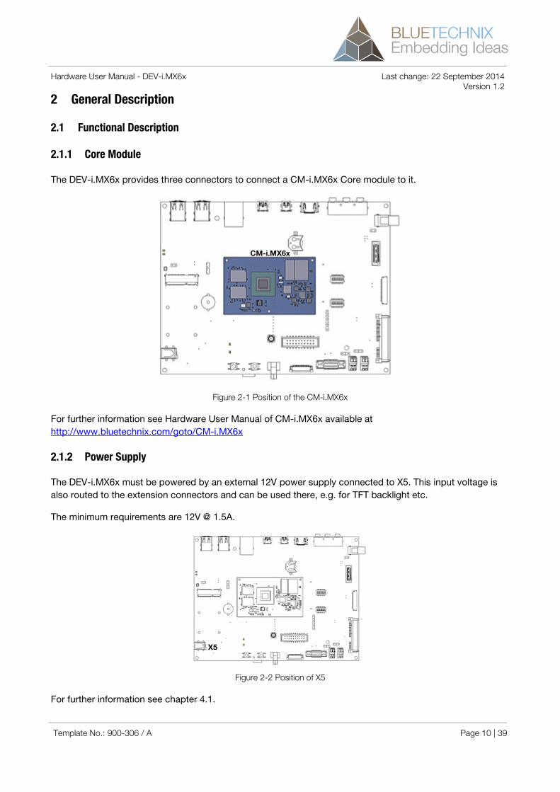
The DEV-i.MX6x provides three connectors to connect a CM-i.MX6x Core module to it.
Figure 2-1 Position of the CM-i.MX6x
For further information see Hardware User Manual of CM-i.MX6x available at http://www.bluetechnix.com/goto/CM-i.MX6x
2.1.2 Power Supply
The DEV-i.MX6x must be powered by an external 12V power supply connected to X5. This input voltage is also routed to the extension connectors and can be used there, e.g. for TFT backlight etc.
The minimum requirements are 12V @ 1.5A.
Figure 2-2 Position of X5
For further information see chapter 4.1.
CM-i.MX6x
X5
Template No.: 900-306 / A Page 10 | 39

Hardware User Manual - DEV-i.MX6x Last change: 22 September 2014 Version 1.2 2.1.3 JTAG
A standard ARM JTAG connector (20 pins, 2.54mm pitch) (X3) is available for processor debugging. For further information see chapter 4.2.
Figure 2-3 Position of X3 and X4
2.1.4 TPIU (Trace Port)
Trace Port (X4) is not supported anymore.
2.1.5 Extension Connector
The DEV-i.MX6x provides an Extension Connector X1 on the bottom side of the board. The connector allows the connection of a Bluetechnix Extension board or a custom designed board. All specifications needed to design a custom board are freely available and Bluetechnix also offers design support for your custom extensions.
Supply Max. Current [mA] Requirement 5V 1000 - 3V3 800 No LVDS display and MiniPCIe card connected
NOTE: Bluetechnix is not responsible for the effects of additional circuit load.
For further information see chapter 4.19.
2.1.1 HDMI
The HDMI connector (X20) provides a standard interface for digital video and audio signals. The HDMI/DVI transmitter is connected to the HDMI interface of the CM-i.MX6x module.
X3
X4
Template No.: 900-306 / A Page 11 | 39

Hardware User Manual - DEV-i.MX6x Last change: 22 September 2014 Version 1.2
Figure 2-4 Position of X20
For further information see chapter 4.18.
2.1.2 Debug UART
The CM-i.MX6x Debug UART (UART4) is routed through a USB/UART bridge (CP2102 Silicon Labs) to the connector X27.
Figure 2-5 Position of X27 and X28
For further information see chapter 4.4.
2.1.3 USB-OTG
The i.MX6x’ internal USB-OTG PHY is routed to a mini USB-A/B connector X28.
For further information see chapter 4.9 and figure 2-5.
2.1.4 Audio Codec
The AUD4 interface of the CM-i.MX6x is routed via an audio codec (SGTL5000) with the I²C address 0x0A to an audio interface connector (X24). It provides a standard PC audio interface with Microphone-In, Line-In and Line-Out. Standard 3,5mm audio jacks are used. A Headset can be connected to the Microphone-In and Line-Out connectors.
X20
X27 X28
Template No.: 900-306 / A Page 12 | 39

Hardware User Manual - DEV-i.MX6x Last change: 22 September 2014 Version 1.2 2.1.5 CAN
Two SN65HVD232D CAN transceiver are present on the DEV-i.MX6x, which allows integration of the board into a CAN bus infrastructure. CAN1 is available on connector X23 and CAN 2 is available on connector X22. The termination resistor can be activated by inserting the appropriate jumper.
Figure 2-6 Position of CAN connectors
Table 2.1: Jumper JP1 and JP2 description
For further information see chapter 4.24.
2.1.6 Ethernet
As the GBit Ethernet PHY is already integrated on the i.MX6x, the LAN signals are routed directly to a RJ45 LAN connector (X2).
Figure 2-7 Position of X2, X26 and X25
For further information see chapter 4.8.
Jumper position Termination resistor JP1 in marked position for CAN2 not connected JP1 in other position for CAN2 connected JP2 in marked position for CAN1 not connected JP2 in other position for CAN1 connected
JP1 JP2
X22 X23
JP2 X26 X25
Template No.: 900-306 / A Page 13 | 39

Hardware User Manual - DEV-i.MX6x Last change: 22 September 2014 Version 1.2 2.1.7 USB
The USBH port of the DEV-i.MX6x is connected to a seven port USB HUB (SMSC USB2517). Therefore the board features two standard dual USB-A connectors (X26 and X25), two USB lanes are routed to the extension connector and one USB lane is routed to the USB/UART Bridge.
For further information see chapter 4.23 and figure 2-7.
2.1.8 SD Card
The SDHC-Card signals are directly connected to the SD1 port of the CM-i.MX6x. A standard SD-Card connector (X7) mounted on the bottom side of the board supports SD and SDHC cards.
For further information see chapter 4.23.
2.1.9 ISM Camera Interface
The camera sensor interface signals (CSI0) are routed to a 30 pin ZIF connector (X21). The connector is compatible to the Bluetechnix ISM interface and allows connecting all available Image Sensor Modules from Bluetechnix (see BLT_ISM_connector).
2.1.10 SATA II
The DEV-i.MX6x allows connecting one SATA II HDD or SSD. The 5.0V supply which is needed for most 2.5” HDDs or SSDs is available on the SATA II connector X29.
The user has to make sure, that no more than 500mA will be drawn from the 5.0V terminal. A 1A fuse is populated on the DEV-board.
2.1.11 PCIe 2.0
Figure 2-8 Position of X17, V9, JP3 and X30
The PCIe interface of the CM-i.Mx6x is routed to connector X17. A RGB-LED (V9) is connected to the MiniPCIe module for debug purposes. A SIM Card holder (X18) is also directly connected to the miniPCIe connector.
For further information see chapter 4.20, chapter 4.21 and figure 2-8.
X17
V9
X30
Template No.: 900-306 / A Page 14 | 39

Hardware User Manual - DEV-i.MX6x Last change: 22 September 2014 Version 1.2 2.1.12 S/PDIF Output
The i.MX6x’ S/PDIF Out signal is routed to the Cinch connector X30.
For further information see chapter 4.25 and figure 2-6.
2.1.13 WIFI / Bluetooth
NOTE: A WiBear-SF1 is mounted on DEV-i.MX6x up to V1.1.1. The WiBear-SF1 is a Wifi+Bluetooth module. A WiBear-11G is mounted on DEV-i.MX6x starting from V1.1.2. The WiBear-11G is a Wifi module. Use a Bluetooth-Dongle connected to the USB interface if you need a Bluetooth interface.
A WiBear-SF1 or WiBear-11G module is mounted on the DEV-i.MX6x. The needed antenna must be connected to SMA connector X31. This antenna is shared by the Wifi and Bluetooth. There are also indicator LEDs on the board (V17 and V16), which shows the activity status of the module.
Figure 2-9 Position of X31
Table 2.2: LED V16 and V17 description
For further information see chapter 4.25.
2.1.14 MIPI CSI
The three lane MIPI CSI interface of the CM-i.MX6x is connected to connector X19.
To use an Omnivision OV5640MRSL or the Raspberry-Pi camera with this interface, a small adapter board is available from Bluetechnix.
LED Status V16 Wifi activity V17 Bluetooth activity
X31 V17
V16
Template No.: 900-306 / A Page 15 | 39

Hardware User Manual - DEV-i.MX6x Last change: 22 September 2014 Version 1.2
Figure 2-10 Position of X19 and X34
For further information see chapter 4.13.
2.1.15 MIPI DSI
The two lane MIPI DSI interface of the CM-i.MX6x is connected to connector X34.
For further information see chapter 4.14 and figure 2-10.
2.1.16 RTC (Real time Clock)
An RTC is mounted on the DEV-i.MX6x and is connected to I2C2 (address 0x51) of the CM-i.MX6x. The RTC backup battery have to be placed into battery holder G1.
For further information see chapter 4.11.
2.1.17 LVDS0
The LVDS0 interface of the CM-i.MX6x is directly connected to connector X12. Connector X10 provides an interface for the display backlight. A resistive touch screen can be connected to X11.
Figure 2-11 Position of JP3 and JP4
JP3
JP4
X19
X34
Template No.: 900-306 / A Page 16 | 39

Hardware User Manual - DEV-i.MX6x Last change: 22 September 2014 Version 1.2
Figure 2-12 Position of the LVDS connectors
Reverse scan function, jumper JP3
This jumper is used to set the reverse scan function.
Table 2.3: Jumper JP3 description
Data input selection, resistor R56
Populate this resistor to set the data input length.
Table 2.4: Resistor R56 description
For further information see chapter 4.15.
2.1.18 LVDS1
The LVDS1 interface of the CM-i.MX6x is directly connected to connector X16. Connector X14 provides an interface for the display backlight. A resistive touch screen can be connected to X15.
Reverse scan function, jumper JP4
This jumper is used to set the reverse scan function.
Table 2.5: Jumper JP4 description
Jumper position Reverse scan function Mounted Activated Not mounted Deactivated
Resistor Data input selection Mounted 8 Bit Not mounted 6 Bit
Jumper position Reverse scan function Mounted Activated Not mounted Deactivated
X16
X15
X14
X12
X11
X10
R56 R58
R61/R63
Template No.: 900-306 / A Page 17 | 39

Hardware User Manual - DEV-i.MX6x Last change: 22 September 2014 Version 1.2 Data input selection, resistor R58
Populate this resistor to set the data input length.
Table 2.6: Resistor R58 description
PWM Dimmer, resistors R61 and R63
The resistors R61 and R63 are used to set the PWM source for dimming the display.
PWM source Mount option PWM_OUT1 (same as LVDS0)
R63 mounted, R61 not mounted
PWM_OUT2 R63 not mounted, R61 mounted
Table 2.7: Resistors R63, R61 description
For further information see chapter 4.15, figure 2-11 and figure 2-12.
2.1.19 Reset Button (S5)
The DEV-i.MX6x provides a reset button (S5) to reset the board.
2.1.20 Power On/Off Button (S6)
The board provides a power on button (S6) to power on/off the core module.
2.1.21 RGB LED (V1)
The RGB LED (V1) is connected to the TCA62724FMG RGB-LED driver and can be used for status signaling. The RGB-LED driver is connected to I²C2 interface of the CM-i.MX6x and its I²C address is set to 0x55.
Figure 2-13 Position of V1
Resistor Data input selection Mounted 8 Bit Not mounted 6 Bit
V1
Template No.: 900-306 / A Page 18 | 39
Hardware User Manual - DEV-i.MX6x Last change: 22 September 2014 Version 1.2
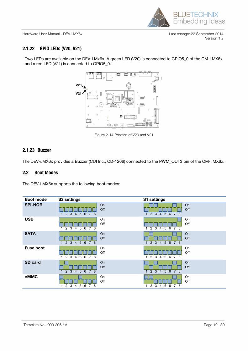
2.1.22 GPIO LEDs (V20, V21)
Two LEDs are available on the DEV-i.Mx6x. A green LED (V20) is connected to GPIO5_0 of the CM-i.MX6x and a red LED (V21) is connected to GPIO5_9.
Figure 2-14 Position of V20 and V21
2.1.23 Buzzer
The DEV-i.MX6x provides a Buzzer (CUI Inc., CD-1206) connected to the PWM_OUT3 pin of the CM-i.MX6x.
2.2 Boot Modes
The DEV-i.MX6x supports the following boot modes:
Boot mode S2 settings S1 settings SPI-NOR On
Off1 2 3 4 5 6 7 8
OnOff
1 2 3 4 5 6 7 8 USB On
Off1 2 3 4 5 6 7 8
OnOff
1 2 3 4 5 6 7 8 SATA On
Off1 2 3 4 5 6 7 8
OnOff
1 2 3 4 5 6 7 8 Fuse boot On
Off1 2 3 4 5 6 7 8
OnOff
1 2 3 4 5 6 7 8 SD card On
Off1 2 3 4 5 6 7 8
OnOff
1 2 3 4 5 6 7 8 eMMC On
Off1 2 3 4 5 6 7 8
OnOff
1 2 3 4 5 6 7 8
V20
V21
Template No.: 900-306 / A Page 19 | 39

Hardware User Manual - DEV-i.MX6x Last change: 22 September 2014 Version 1.2
Table 2-8 Boot mode switch settings
Figure 2-15 Position of S1 and S2
S2
S1
Template No.: 900-306 / A Page 20 | 39

Hardware User Manual - DEV-i.MX6x Last change: 22 September 2014 Version 1.2
3 Specifications
3.1 Electrical Specifications
3.1.1 Operating Conditions
Symbol Parameter Min Typical Max Unit VIN Input supply voltage 11 12 15 V P Board Power Consumption1) TBD - TBD W VUSBx USB Supply Voltage 4.5 5.0 5.5 V IUSBx USB Supply Current - - 500 mA
Table 3-1: Electrical characteristics
1) The Power consumption refers to a CM-i.MX6x with Android running in idle state and no Extension Boards or USB-Devices plugged in.
3.1.2 Maximum Ratings
Stressing the device above the rating listed in the absolute maximum ratings table may cause permanent damage to the device. These are stress ratings only. Operation of the device at these or any other conditions greater than those indicated in the operating sections of this specification is not implied. Exposure to absolute maximum rating conditions for extended periods may affect device reliability.
Symbol Parameter Min Max Unit VIO Input or output voltage -0.5 3.6 V VIN Input supply voltage 10 16 V TAMB Ambient temperature 0 70 °C TSTO Storage temperature -20 85 °C φAMB Relative ambient humidity 90 %
Table 3-2: Absolute maximum ratings
3.1.3 ESD Sensitivity
ESD (electrostatic discharge) sensitive device. Charged devices and circuit boards can discharge without detection. Although this product features patented or proprietary protection circuitry, damage may occur on devices subjected to high energy ESD. Therefore, proper ESD precautions should be taken to avoid performance degradation or loss of functionality.
Template No.: 900-306 / A Page 21 | 39

Hardware User Manual - DEV-i.MX6x Last change: 22 September 2014 Version 1.2
4 Connector Description
4.1 X5 - Power supply
This is the main power supply connector for the board. Use a standard DC power plug with 5.5x2.5mm diameter to power the board.
Minimum requirements for external power supply: 12V @ 1.5A.
Figure 4-1 Polarity of the external power supply
Descriptor Description Manufacturer Part Number X5 DC Power, RA Cui CUI-PJ-002AH-SMT
Mating Connector DC Power Plug Cliff Electronic Components DCPP2
Table 4-1: Connector description X5
4.2 X3 – JTAG
The JTAG interface of the Core Module is connected to the 20-pin 2.54mm header, X3. The JTAG connector is compliant with any ARM JTAG Emulator. (e.g ARM DSTREAM)
4.3 X27 – Debug UART
The USB Mini-B connector X27 provides access to the Debug UART (UART4) through the USB to UART Bridge.
Descriptor Description Manufacturer Part Number X27 USB Mini-B, RA Molex 675031020
Mating Cable USB Mini-B OTG-STD A Molex 88732-8600
Table 4-2: Connector description X27
4.4 X6 – I²C
The header connector X6 (not mounted) provides access to the I²C2 signals of the CM-i.MX6x Core Module.
Descriptor Description Manufacturer Part Number X6 Header, 4-Pin Harwin M20-9990445
Mating Connector Crimp housing, 4-Way Harwin M20-1060400
Table 4-3: Connector description X6
Template No.: 900-306 / A Page 22 | 39
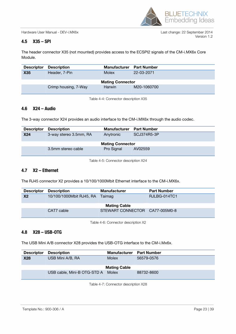
Hardware User Manual - DEV-i.MX6x Last change: 22 September 2014 Version 1.2 4.5 X35 – SPI
The header connector X35 (not mounted) provides access to the ECSPI2 signals of the CM-i.MX6x Core Module.
Descriptor Description Manufacturer Part Number X35 Header, 7-Pin Molex 22-03-2071
Mating Connector Crimp housing, 7-Way Harwin M20-1060700
Table 4-4: Connector description X35
4.6 X24 – Audio
The 3-way connector X24 provides an audio interface to the CM-i.MX6x through the audio codec.
Descriptor Description Manufacturer Part Number X24 3-way stereo 3.5mm, RA Anytronic SCJ374R5-3P
Mating Connector 3.5mm stereo cable Pro Signal AV02559
Table 4-5: Connector description X24
4.7 X2 – Ethernet
The RJ45 connector X2 provides a 10/100/1000Mbit Ethernet interface to the CM-i.MX6x.
Descriptor Description Manufacturer Part Number X2 10/100/1000Mbit RJ45, RA Taimag RJLBG-014TC1
Mating Cable CAT7 cable STEWART CONNECTOR CA77-005M0-8
Table 4-6: Connector description X2
4.8 X28 – USB-OTG
The USB Mini A/B connector X28 provides the USB-OTG interface to the CM-i.Mx6x.
Descriptor Description Manufacturer Part Number X28 USB Mini A/B, RA Molex 56579-0576
Mating Cable USB cable, Mini-B OTG-STD A Molex 88732-8600
Table 4-7: Connector description X28
Template No.: 900-306 / A Page 23 | 39

Hardware User Manual - DEV-i.MX6x Last change: 22 September 2014 Version 1.2 4.9 X7 – SD-Card slot
The SD-Card slot X7 provides an interface to a SD-Card through the SD1 interface.
Descriptor Description Manufacturer Part Number X7 SD-Card slot Multicomp MC34459
Mating Card SDHC Ultra II Sandisk SD4814
Table 4-8: Connector description X7
4.10 G1 – Backup battery holder
The backup battery holder provides a power supply to the RTC when no external power supply is applied to the board.
Descriptor Description Manufacturer Part Number G1 Battery holder, 1216/1220/1225 Keystone Electronics 3000TR
Mating Battery 3V Lithium battery Multicomp CR1220
Table 4-9: Connector description G1
4.11 X21 – ISM Camera
The ISM connector provides an interface to Bluetechnix ISM camera modules.
Descriptor Description Manufacturer Part Number X21 FFC/FPC Connector, 0.5mm, 30 Pos., RA Samtec ZF5-30-02-T-WT
Mating Cable ZIF Cable, 0.5mm, 50mm, 30Pos Samtec FJH-30-D-02.00-4
Mating Modules Aptina MT9M025 Bluetechnix GmbH ISM-MT9M025 Aptina MT9M131 Bluetechnix GmbH ISM-MT9M131-Color Aptina MT9P031 Bluetechnix GmbH ISM-MT9P031 See www.bluetechnix.com
Table 4-10: Connector description X21
4.12 X19 – MIPI CSI
The connector X19 provides an interface to the MIPI CSI interface of the CM-i.MX6x module.
Descriptor Description Manufacturer Part Number X19 DF19, 1mm, 20 Pos., RA Hirose DF19G-20P-1H(54)
Mating Cable DF19 cables, 20 Pos.*) Various DF19 cables, 20 Pos.*)
Template No.: 900-306 / A Page 24 | 39

Hardware User Manual - DEV-i.MX6x Last change: 22 September 2014 Version 1.2 Descriptor Description Manufacturer Part Number
Mating Modules TBD
Table 4-11: Connector description X19
*) Can be ordered from Bluetechnix GmbH.
4.13 X34 – MIPI DSI
The connector X34 provides an interface to the MIPI DSI interface of the CM-i.MX6x module.
Descriptor Description Manufacturer Part Number X34 QSH-030-01-L-D-A Samtec QSH-030-01-L-D-A
Mating Connector QTH-030-01-L-D-A Samtec QTH-030-01-L-D-A
Mating Modules TBD
Table 4-12: Connector description X34
4.14 X12 and X16 – LVDS Display
The LVDS display connectors provides interfaces to TFT (touch) displays.
Descriptor Description Manufacturer Part Number X12 and X16 DF19, 1mm, 20 Pos., RA Hirose DF19G-20P-1H(54)
Mating Cable DF19 cables, 20 Pos.*) Various -
Mating Display 10.4” TFT-LCD Module*) Promate 97G104S2N2F-2
Table 4-13: Connector description X12 and X16
*) Can be ordered from Bluetechnix GmbH.
4.15 X10 and X14 – Display Backlight
The display backlight connectors provides interfaces to TFT (touch) displays.
Descriptor Description Manufacturer Part Number X10 and X14 1.25mm, 5 Pos., RA Molex WM7602CT-ND
Mating Cable KR1253H-05P cables, 5 Pos.*) Various -
Mating Display 10.4” TFT-LCD Module*) Promate 97G104S2N2F-2
Table 4-14: Connector description X10 and X14
Template No.: 900-306 / A Page 25 | 39

Hardware User Manual - DEV-i.MX6x Last change: 22 September 2014 Version 1.2 *) Can be ordered from Bluetechnix GmbH.
4.16 X11 and X15 – Touch screen
The touch screen connectors provides interfaces to 4-wire resistive TFT touch screen display.
Descriptor Description Manufacturer Part Number X11 and X15 FFC/FPC, 1mm, 4 Pos., RA Tyco Electronics 84953-4
Mating Display 10.4” TFT-LCD Module*) Promate 97G104S2N2F-2
Table 4-15: Connector description X11 and X15
*) Can be ordered from Bluetechnix GmbH.
4.17 X20 – HDMI
The HDMI Type A connector provides a high-definition multimedia interface to the DEV-i.MX6x.
Descriptor Description Manufacturer Part Number X20 HDMI Type A, RA FCI 10029449-001RLF
Mating Cable HDMI-A-A, 1.8m Pro Signal 127790
Table 4-16: Connector description X20
4.18 X1 – Extension Connector
The extension connector provide an interface to connect custom-designed extension boards to the DEV-i.MX6x.
Descriptor Description Manufacturer Part Number X1 FX10-100P female Hirose FX10A-100P/10-SV
Mating Connector FX10-100P female. Hirose FX10A-100S/10-SV
Table 4-17: Connector description X1
4.19 X17 – Mini PCI express
The Mini PCI express connector provides a MiniPCIe interface to the DEV-i.MX6x.
Descriptor Description Manufacturer Part Number X17 MiniPCIe connector JAE MM60-52B1-B1-R850
Mating Cards MiniPCIe cards Various -
Template No.: 900-306 / A Page 26 | 39

Hardware User Manual - DEV-i.MX6x Last change: 22 September 2014 Version 1.2
Table 4-18: Connector description X17
4.20 X18 – SIM card
The SIM card connector X18 is directly connected to the MiniPCIe connector.
Descriptor Description Manufacturer Part Number X18 SIM card connector C&K CCM03-3013 R102
Mating Cards Mini SIM cards Various -
Table 4-19: Connector description X18
4.21 X29 – SATA II
The SATA II connector provides a SATA II interface to the DEV-i.MX6x.
Descriptor Description Manufacturer Part Number X29 SATA connector FCI 10029364-001LF
Mating Cable Cable SATA 15pin to 15pin ROLINE 11.03.1042
Table 4-20: Connector description X29
4.22 X25 and X26 – USB
The connectors X25 and X26 provide four USB Host interfaces to the DEV-i.MX6x.
Descriptor Description Manufacturer Part Number X25 and X26 Dual USB connector Multicomp MC32594
Mating Cable USB A/B cable Various -
Table 4-21: Connector description X25 and X26
4.23 X22 and X23 – CAN
The connectors X22 and X23 provide access to the CAN bus.
Descriptor Description Manufacturer Part Number X22 and X23 PCB Terminal Wago 233-202
Mating Wire Wire 0.08 mm² – 0.5 mm² Various -
Table 4-22: Connector description X22 and X23
Template No.: 900-306 / A Page 27 | 39

Hardware User Manual - DEV-i.MX6x Last change: 22 September 2014 Version 1.2 4.24 X30 – S/PDIF
The connector X30 provides an S/PDIF output to the DEV-i.MX6x.
Descriptor Description Manufacturer Part Number X30 Cinch connector Pro Signal PSG01547
Mating Cable Cinch cable Various -
Table 4-23: Connector description X30
4.25 X31 – WIFI / BT Antenna
The connector X31 provides an S/PDIF output to the DEV-i.MX6x.
Descriptor Description Manufacturer Part Number X31 SMA connector Multicomp 19-46-2-TGG
Mating Antennas 2.4GHz SMA Antenna*) Various -
Table 4-24: Connector description X31
*) Can be ordered from Bluetechnix GmbH.
Template No.: 900-306 / A Page 28 | 39

Hardware User Manual - DEV-i.MX6x Last change: 22 September 2014 Version 1.2
5 Application Information
5.1 Application Example Schematics
Have a look at our DEV-i.MX6 schematics, which can be found at http://www.bluetechnix.com/goto/dev-i.mx6 to get application examples.
Template No.: 900-306 / A Page 29 | 39

Hardware User Manual - DEV-i.MX6x Last change: 22 September 2014 Version 1.2
6 Mechanical Outline
This section shows the mechanical outline of the DEV-i.MX6x. All dimensions are given in mm.
6.1 Top View
Figure 6-1 Mechanical outline top view
Template No.: 900-306 / A Page 30 | 39

Hardware User Manual - DEV-i.MX6x Last change: 22 September 2014 Version 1.2 6.2 Bottom View
Figure 6-2 Mechanical outline bottom view
6.3 Side View
Figure 6-3 Mechanical outline side view
Template No.: 900-306 / A Page 31 | 39

Hardware User Manual - DEV-i.MX6x Last change: 22 September 2014 Version 1.2
7 Support
7.1 General Support
General support for products can be found at Bluetechnix’ support site https://support.bluetechnix.at/wiki
7.2 Board Support Packages
Board support packages and software downloads are available at https://support.bluetechnix.at/wiki/I.MX6
7.3 i.MX Software Support
7.3.1 Linux
Linux BSP and images of derivates can be found at Bluetechnix’ support site https://support.bluetechnix.at/wiki at the software section of the related product.
7.3.2 Android
Please contact Bluetechnix for support information.
7.3.3 Win CE
Please contact Bluetechnix for support information.
7.4 i.MX Design Services
Based on more than seven years of experience with Blackfin and i.MX, Bluetechnix offers development assistance as well as custom design services and software development.
7.4.1 Upcoming Products and Software Releases
Keep up to date with all product changes, releases and software updates of Bluetechnix at http://www.bluetechnix.com.
Template No.: 900-306 / A Page 32 | 39

Hardware User Manual - DEV-i.MX6x Last change: 22 September 2014 Version 1.2
8 Ordering Information
Article Number
Name Temperature Range
100-4126-1 i.MX6Q Development Starter Package Commercial 100-4127-1 i.MX6Q Development Starter Package Industrial
Table 8-1: Ordering information
NOTE: Custom Core Modules are available on request! Please contact Bluetechnix ([email protected]) if you are interested in custom Core Modules.
Template No.: 900-306 / A Page 33 | 39

Hardware User Manual - DEV-i.MX6x Last change: 22 September 2014 Version 1.2
9 Dependability
9.1 MTBF
Please keep in mind that a part stress analysis would be the only way to obtain significant failure rate results, because MTBF numbers just represent a statistical approximation of how long a set of devices should last before failure. Nevertheless, we can calculate an MTBF of the development board using the bill of material. We take all the components into account. The PCB and solder connections are excluded from this estimation. For test conditions we assume an ambient temperature of 30°C of all development board components. We use the MTBF Calculator from ALD (http://www.aldservice.com/) and use the reliability prediction MIL-217F2 Part Stress standard. Please get in touch with Bluetechnix ([email protected]) if you are interested in the MTBF result.
Template No.: 900-306 / A Page 34 | 39

Hardware User Manual - DEV-i.MX6x Last change: 22 September 2014 Version 1.2
10 Product History
10.1 Version Information
Version Component Type 1.0.0 4 Port USB Hub
WIFI/Bluetooth module RTC Audio Codec CAN Transceiver
USB2517 WiBear-SF PCF2129AT/1 SGTL5000 SN65HVD232D
1.1.0 4 Port USB Hub WIFI/Bluetooth module RTC Audio Codec CAN Transceiver
USB2517 WiBear-SF PCF2129AT/1 SGTL5000 SN65HVD232D
1.1.1 4 Port USB Hub WIFI/Bluetooth module RTC Audio Codec CAN Transceiver
USB2517 WiBear-SF PCF2129AT/1 SGTL5000 SN65HVD232D
1.1.2 4 Port USB Hub WIFI/Bluetooth module RTC Audio Codec CAN Transceiver
USB2517 WiBear-11G PCF2129AT/1 SGTL5000 SN65HVD232D
Table 10-1: Overview DEV-i.MX6x product changes
10.2 Anomalies
Version Date Description V1.0 2013 04 05 No anomalies reported yet. V1.1 2013 11 18 TPUI (Trace Port) is not supported anymore V1.1 2014 09 22 Boot from SD card after HW reset is not working.
Reason: 3V3 is not 0V when EN_PERI goes low. Solution: Power cycle the DEV-i.MX6x to boot from SD card.
Table 10-2 – Product anomalies
Template No.: 900-306 / A Page 35 | 39

Hardware User Manual - DEV-i.MX6x Last change: 22 September 2014 Version 1.2
11 Document Revision History
Version Date Document Revision 0 2013 04 05 First release V1.0 of the Document 1 2013 09 27 Updated for Hardware Version V1.1 2 2014 09 22 Anomaly “Boot from SD card” added to chapter 10.2
Version 1.1.2 added to chapter 10.1 Chapter 2.1.13 update
Table 11-1: Revision history
Template No.: 900-306 / A Page 36 | 39

Hardware User Manual - DEV-i.MX6x Last change: 22 September 2014 Version 1.2
12 List of Abbreviations
Abbreviation Description ADI Analog Devices Inc. AI Analog Input AMS Asynchronous Memory Select AO Analog Output CM Core Module DC Direct Current DSP Digital Signal Processor eCM Enhanced Core Module EBI External Bus Interface ESD Electrostatic Discharge GPIO General Purpose Input Output I Input I²C Inter-Integrated Circuit I/O Input/Output ISM Image Sensor Module LDO Low Drop-Out regulator MTBF Mean Time Between Failure NC Not Connected NFC NAND Flash Controller O Output OS Operating System PPI Parallel Peripheral Interface PWR Power RTOS Real-Time Operating System SADA Stand Alone Debug Agent SD Secure Digital SoC System on Chip SPI Serial Peripheral Interface SPM Speech Processing Module SPORT Serial Port TFT Thin-Film Transistor TISM Tiny Image Sensor Module TSC Touch Screen Controller UART Universal Asynchronous Receiver Transmitter USB Universal Serial Bus USBOTG USB On The Go ZIF Zero Insertion Force
Table 12-1: List of abbreviations
Template No.: 900-306 / A Page 37 | 39

Hardware User Manual - DEV-i.MX6x Last change: 22 September 2014 Version 1.2
A List of Figures and Tables
Figures
Figure 1-1 Overview of the main components .................................................................................................... 7 Figure 2-1 Position of the CM-i.MX6x ............................................................................................................... 10 Figure 2-2 Position of X5 ................................................................................................................................... 10 Figure 2-3 Position of X3 and X4 ....................................................................................................................... 11 Figure 2-4 Position of X20 ................................................................................................................................. 12 Figure 2-5 Position of X27 and X28................................................................................................................... 12 Figure 2-6 Position of CAN connectors ............................................................................................................ 13 Figure 2-7 Position of X2, X26 and X25 ............................................................................................................ 13 Figure 2-8 Position of X17, V9, JP3 and X30 .................................................................................................... 14 Figure 2-9 Position of X31 ................................................................................................................................. 15 Figure 2-10 Position of X19 and X34................................................................................................................. 16 Figure 2-11 Position of JP3 and JP4................................................................................................................. 16 Figure 2-12 Position of the LVDS connectors ................................................................................................... 17 Figure 2-13 Position of V1 ................................................................................................................................. 18 Figure 2-14 Position of V20 and V21................................................................................................................. 19 Figure 2-15 Position of S1 and S2 .................................................................................................................... 20 Figure 4-1 Polarity of the external power supply .............................................................................................. 22 Figure 6-1 Mechanical outline top view ............................................................................................................ 30 Figure 6-2 Mechanical outline bottom view ...................................................................................................... 31 Figure 6-3 Mechanical outline side view ........................................................................................................... 31
Tables
Table 2.1: Jumper JP1 and JP2 description ..................................................................................................... 13 Table 2.2: LED V16 and V17 description........................................................................................................... 15 Table 2.3: Jumper JP3 description ................................................................................................................... 17 Table 2.4: Resistor R56 description .................................................................................................................. 17 Table 2.5: Jumper JP4 description ................................................................................................................... 17 Table 2.6: Resistor R58 description .................................................................................................................. 18 Table 2.7: Resistors R63, R61 description ........................................................................................................ 18 Table 2-8 Boot mode switch settings ............................................................................................................... 20 Table 3-1: Electrical characteristics .................................................................................................................. 21 Table 3-2: Absolute maximum ratings .............................................................................................................. 21 Table 4-1: Connector description X5 ................................................................................................................ 22 Table 4-2: Connector description X27 .............................................................................................................. 22 Table 4-3: Connector description X6 ................................................................................................................ 22 Table 4-4: Connector description X35 .............................................................................................................. 23 Table 4-5: Connector description X24 .............................................................................................................. 23 Table 4-6: Connector description X2 ................................................................................................................ 23 Table 4-7: Connector description X28 .............................................................................................................. 23 Table 4-8: Connector description X7 ................................................................................................................ 24 Table 4-9: Connector description G1 ................................................................................................................ 24 Table 4-10: Connector description X21 ............................................................................................................ 24 Table 4-11: Connector description X19 ............................................................................................................ 25 Table 4-12: Connector description X34 ............................................................................................................ 25 Table 4-13: Connector description X12 and X16 .............................................................................................. 25 Table 4-14: Connector description X10 and X14 .............................................................................................. 25 Table 4-15: Connector description X11 and X15 .............................................................................................. 26 Table 4-16: Connector description X20 ............................................................................................................ 26 Table 4-17: Connector description X1 .............................................................................................................. 26 Table 4-18: Connector description X17 ............................................................................................................ 27
Template No.: 900-306 / A Page 38 | 39

Hardware User Manual - DEV-i.MX6x Last change: 22 September 2014 Version 1.2 Table 4-19: Connector description X18 ............................................................................................................ 27 Table 4-20: Connector description X29 ............................................................................................................ 27 Table 4-21: Connector description X25 and X26 .............................................................................................. 27 Table 4-22: Connector description X22 and X23 .............................................................................................. 27 Table 4-23: Connector description X30 ............................................................................................................ 28 Table 4-24: Connector description X31 ............................................................................................................ 28 Table 8-1: Ordering information ........................................................................................................................ 33 Table 10-1: Overview DEV-i.MX6x product changes ........................................................................................ 35 Table 10-2 – Product anomalies ....................................................................................................................... 35 Table 11-1: Revision history .............................................................................................................................. 36 Table 12-1: List of abbreviations ....................................................................................................................... 37
Template No.: 900-306 / A Page 39 | 39