
Detroit Diesel Series 53 Operators Manual
538
TM 5-3895-355-14&P TECHNICAL MANUAL OPERATOR'S, ORGANIZATIONAL, DIRECT SUPPORT AND GENERAL SUPPORT MAINTENANCE MANUAL (INCLUDING REPAIR PARTS INFORMATION AND SUPPLEMENTAL MAINTENANCE AND REPAIR PARTS INSTRUCTIONS) FOR PAVING MACHINE BITUMINOUS MATERIEL CRAWLER MOUNTED DED MODEL BSF-400 (NSN 3895-01-063-7891) WITH DETROIT DIESEL ENGINE (SERIES 53) IOWA MANUFACTURING COMPANY HEADQUARTERS, DEPARTMENT OF THE ARMY JANUARY 1981
-
Upload
dennis-klineman -
Category
Documents
-
view
524 -
download
32
description
DETROIT DIESEL SERIES 53 OPERATORS MANUAL. THIS IS THE OPERATORS MANUAL FOR ALL 53 DIESEL ENGINES THAT DETROIT MADE. SOON TO BE FOLLOWED BY THE SERVICE MANUAL.
Transcript of Detroit Diesel Series 53 Operators Manual
TM 5-3895-355-14&P
TECHNICAL MANUAL
OPERATOR'S , ORGANIZATIONAL,
D IRECT SUPPORT AND GENERAL SUPPORT
MAINTENANCE MANUAL
( INCLUDING REPAIR PARTS INFORMATION AND SUPPLEMENTAL
MAINTENANCE AND REPAIR PARTS INSTRUCTIONS)
FOR
PAVING MACHINE B ITUMINOUS MATERIEL CRAWLER
MOUNTED DED
MODEL BSF-400
(NSN 3895-01 -063-7891)
WITH
DETROIT D IESEL ENGINE (SERIES 53 )
IOWA MANUFACTURING COMPANY
H E A D Q U A R T E R S , D E P A R T M E N T O F T H E A R M Y
JANUARY 1981
IMPORTANT NOTICE!
Federal, State and Local Safety Regulations must be complied with to prevent possible danger to person(s) or property,from accidents or harmful exposure. This equipment must be used in accordance with all operation and maintenanceinstructions.
(1) Read all warning, caution and instruction signs. Know what guards and protective devices are included and seethat each item is in place. Additional guards and protective devices, that may be required due to proximity torelated equipment, must be installed by the user (owner) before operating.
(2) NEVER LUBRICATE OR ADJUST EQUIPMENT WHEN IT IS IN MOTION!(3) Always establish a positive lockout of the involved power source and block parts if necessary to prevent motion
before performing maintenance, cleaning, adjusting or repair work. Secure the power source lockout to preventstart-up by other persons.
(4) Wear a protective mask whenever harmful air pollution exists.(5) Use ear plugs wherever the noise level is above established acceptable limits.
SAFETY IS YOUR BUSINESS
Safety, based on technical skill and years of experience, has been carefully built intoyour Detroit Diesel engine. Time, money and effort have been invested in making yourdiesel engine a safe product. The dividend you realize from this investment is yourpersonal safety.
It should be remembered, however, that power-driven equipment is only as safe as theman who is at the controls. You are urged, as the operator of this diesel engine, to keepyour fingers and clothing away from the revolving "V" belts, gears, blower, fan, driveshafts, etc.
An accident can be prevented with your help.
a

SAFETY RECOMMENDATIONS
CEDARAPIDS Equipment is designed with the safety of all personnel in mind. Guards, covers and shields are addedwhenever necessary to prevent accidental injury to operators and others working on or near the equipment.
The following basic safety recommendations should be followed:
1. All guards and covers should be replaced after adjustment or maintenance of equipment.
2. Make sure handrails and walkways are on good repair and clear of tools, spare parts and obstructions.
3. Never adjust or lubricate equipment while it is operating.
4. Stand clear of hauling equipment that is dumping material into the hopper.
5. Always look around equipment before start-up to make sure no one is near moving parts, making inspection oradjustment.
6. Do not drop material or tools from walkways or ladders without being positive that no one is below.
7. Blocking under-and around plants must be suitable material and properly placed to support the structure.Periodically check blocking for signs of failure or shifting that could allow structure to fall.
8. Electricians should handle any kind of work on electrical equipment. Avoid touching any loose or misplacedelectrical wires. Consider them all dangerous.
9. Mark all inflammable materials; such as, oils, greases, and gasoline. Store these materials in an incombustiblebuilding situated away from the operating plant. NO SMOKING while handling flammable material.
10. Proper clothing while on the job is important. Wear shoes with safety toes to protect your toes from falling objects.Do not wear loosely hanging clothes or neck ties on the job. This type of clothing will get caught in moving partsof the equipment and-generally hinders work. The use of hard hats and safety glasses or goggles are definitesafety protective equipment and are required by many safety conscious contractors.
11. Think safety! If you have and maintain an attitude of safety on the job, then the chances of being injured are verygreatly reduced. Point out hazards and instruct new employees on safety.
b

GUIDE TO GROUNDING SAFEGUARDS
ON ELECTRICALLY POWERED EQUIPMENT
1. Each electric drive motor must have its frameelectrically bonded to its controlling starter. This is to beby a conductor of equal size to the conductors feedingpower to the motor. The bonding shall be by the junctionbox mounting bolt at the motor end, and by a startermounting bolt at the starter end. The bonding must be bytight connection of clean metal to clean metal.
2. All electric motor starters on a unit (separate piece ofequipment) must have their cases (enclosures) bonded toeach other, and to the metal structure of the unit.
3. All individually mounted push button units (notmounted on the starter covers) must have their cases(enclosures) bonded to the starter enclosure or encloses.
4. When electric drives are used on one or moreportable units (separate pieces of equipment) in aninstallation, the metallic supporting structures of all unitsused in that installation must be bonded to each other bya bonding wire having a size rating of not less than#6AWG, and equal in size to the largest power supplyingconductor. It is especially important that portable unitsusing no electric drives be bonded to electrically drivenunits.
5. The starter or group of starters on each unit musthave their cases (enclosures) bonded to the main powersupply disconnect case (enclosure). This may be by agrounding conductor or conductors in the power supplycable(s).
6. The main power disconnect case (enclosure) must bebonded to the ground approved by the power supplycompany when electric energy is purchased, or to thegenerator common-ground when electric energy is beinggenerated by one or more engine-generator sets.
7. Each generator of engine-generator installations musthave its case (frame) bonded to the neutral connection ofthe generator power windings. This connection we referto as the "common generator ground".
8. The common generator ground(s) must, whereverpossible, be connected to a driven or plate earth groundin accordance with Article 250, Section H, of the 1962National Electric Code.
9. In addition to the earth ground at the commongenerator grounds(s), there must also be at least oneearth ground of the driven rod type or plate type to whichthe metallic supporting structures of the units are bonded.When operating a group of. highly portable units, such asin a quarry installation, the portable unit or units nearestthe moist earth (quarry face) and nearest the metallicmounted equipment (track mounted shovel, etc.) shallhave earth grounds.
10. When plugs and receptacles are used as a means ofdisconnecting power supplying or distributing lines, theplugs and receptacles shall have separate connections forthe bonding wire(s). Wherever possible, theseconnections should be by separate pins rather than by theplug and receptacle cases.
11. Damaged electric power supply cables and damagedelectric power distribution cables are hazardous. Allexposed electric power supply conductors or exposedelectric terminals must be guarded against accidentalcontact by operating personnel.
12. Manufacturers of equipment using electrical productscannot be responsible for owners and operators safetyunless the above recommendations are followed...PlaySafe ...Electrical Currents Can Kill.
c

INTRODUCTION
To The Owner and Operator:In this manual we have tried to provide information which will give you a clear understanding of equipment construction,function, capabilities and requirements. The details are compiled from the knowledge and experience of highly qualifiedpeople at our factory and in our field organizations. By reading and using this information we believe you can betterobtain the highest degree of performance efficiency, the maximum service life from normal wear-absorption parts, andthe lowest possible maintenance expense. It is our strong recommendation that all persons directly involved with theequipment, be familiar with the contents of this manual.
Respectfully,IOWA MANUFACTURING COMPANY
TO THE OPERATORThis manual contains instructions on the operation and preventive maintenance of yourDetroit Diesel engine. Sufficient descriptive material, together with numerousillustrations, is included to enable the operator to understand the basic construction ofthe engine and the principles by which it functions. This manual does not cover enginerepair or overhaul.
Whenever possible, it will pay to rely on an authorized Detroit Diesel Allison ServiceOutlet for all your service needs from maintenance to major parts replacement. Thereare over 1500 authorized service outlets in the U.S. and Canada. They stock factoryoriginal parts and have the specialized equipment and personnel with technicalknowledge to provide skilled and efficient workmanship.
The operator should familiarize himself thoroughly with the contents of the manualbefore running an engine, making adjustments, or carrying out maintenance procedures.
The information, specifications and illustrations in this publication are based on theinformation in effect at the time of approval for printing. Generally, this publication isreprinted annually. It is recommended that users contact an authorized Detroit DieselAllison Service Outlet for information on the latest revision. The right is reserved tomake changes at any time without obligation.
WARRANTY
The applicable engine warranty is contained in the form entitled POLICY ON OWNERSERVICE, available from authorized Detroit Diesel Allison Service Outlets.
d

This manual contains copyright material and published with permission of Detroit Diesel Allison, Division of GeneralMotors Corporation: and Iowa Manufacturing Company.
TM 5-3895-355-14&P
TECHNICAL MANUAL HEADQUARTERSDEPARTMENT OF THE ARMY
No. 5-3895-355-14&P WASHINGTON, DC, 26 January 1981
Operator's,. Organizational, Direct Support and General SupportMaintenance Manual
(Including Repair Parts Information and Supplemental'Maintenance and Repair Parts Instructions)
ForPAVING MACHINE BITUMINOUS MATERIEL CRAWLER MOUNTED DED
MODEL BSF-400(NSN 3895-01-063-7891)
WITHDETROIT DIESEL ENGINE (SERIES 53)
IOWA MANUFACTURING COMPANY
REPORTING OF ERRORSYou can help improve this manual. If you find any mistake or if you know of a way to improve the procedures,please let us know. Mail your letter, DA Form 2028 (Recommended Changes to Publications and Blank Forms),or DA Form 2028-2 located in the back of this manual direct to: Commander, US Army Tank-AutomotiveCommand, ATTN: DRSTA-MB, Warren, MI 48090. A reply will be furnished to you.
NOTEThis manual is published for the purpose of identifying an authorized commercial manual for the use ofthe personnel to whom the paving machine is issued.Manufactured by: Detroit Diesel Allison, Division of General Motors Corp.
Iowa Manufacturing CompanyProcured under Contract Nos: DSA 700-77-C-8481 and DAAE07-79-C5795
This technical manual is an authentication of the manufacturers' commercial literature and does not conformwith the format and content specified in AR 310-3, Military Publications. This technical manual does, however,contain available information that is essential to the operation and maintenance of the equipment.
Part I. Operators Instructions for Series 53 EngineII. Parts Listing for Detroit Diesel Engine
III. Equipment Operation and Maintenance InstructionsIV. Vane PumpsV. Service Instructions for Cyclopac Series Air Cleaners
VI. Parts Listing for Paving Machine, Bituminous Material, Crawler Mounted, Model BSF-400VII, Supplemental Operating, Maintenance and Repair Parts Instructions
i

PART I. OPERATOR'S INSTRUCTIONSFor Series 53 EnginesTABLE OF CONTENTS
SUBJECT PAGE
DESCRIPTIONPrinciples of Operation................................................................................................................................... 4General Description ....................................................................................................................................... 5Model Description .......................................................................................................................................... 6General Specifications ................................................................................................................................... 8Engine Model and Serial Number -Designation .............................................................................................. 9Built-In Parts Book ......................................................................................................................................... 9Cross Section Views of Engine....................................................................................................................... 10
ENGINE SYSTEMSFuel System................................................................................................................................................... 13Air System ..................................................................................................................................................... 17Lubricating System......................................................................................................................................... 22Cooling System.............................................................................................................................................. 25
ENGINE EQUIPMENTInstrument Panel, Instruments and Controls ................................................................................................... 31Engine Protective Systems ............................................................................................................................ 33Electrical Starting System .............................................................................................................................. 37Hydraulic Starting System.............................................................................................................................. 38Cold Weather Starting Aids ............................................................................................................................ 41Governors ...................................................................................................................................................... 44Transmissions ................................................................................................................................................ 44
OPERATING INSTRUCTIONSEngine Operating Instructions ........................................................................................................................ 47A. C. Power Generator Set Operating Instructions.......................................................................................... 51
LUBRICATION AND PREVENTIVE MAINTENANCELubrication and Preventive Maintenance........................................................................................................ 55Fuel, Lubricants and Coolants ........................................................................................................................ 66
ENGINE TUNE-UP PRO)CEDURESEngine Tune-Up Procedures .......................................................................................................................... 77Exhaust Valve Clearance Adjustment ............................................................................................................ 78Timing Fuel Injector ....................................................................................................................................... 80Limiting Speed Mechanical Governor (In-Line Engines) ................................................................................. 81Limiting Speed Mechanical Governor (6V-53 Engine) .................................................................................... 86Variable Speed Mechanical Governor (In-Line Open Linkage) ....................................................................... 91Variable Speed Mechanical Governor (In-Line Enclosed Linkage).................................................................. 95Variable Speed Mechanical Governor (6V-53 Engine).................................................................................... 100Supplementary Governing Device Adjustment ............................................................................................... 105Hydraulic Governor (In-Line Engine) .............................................................................................................. 109Hydraulic Governor (6V-53 Engine)................................................................................................................ 112
STORAGE ..................................................................................................................................................... 113
BUILT-IN PARTS BOOK ............................................................................................................................... 117
OWNER ASSISTANCE.................................................................................................................................. 141
ALPH ABETICAL INDEX ............................................................................................................................... 143Page 3
DESCRIPTION
PRINCIPLES OF OPERATION
The diesel engine is an internal combustion power unit, in which the heat of fuel is converted into work in the cylinder ofthe engine.
In the diesel engine, air alone is compressed in the cylinder; then, after the air has been compressed, a charge of fuel issprayed into the cylinder and ignition is accomplished by the heat of compression.
The Two-Cycle Principle
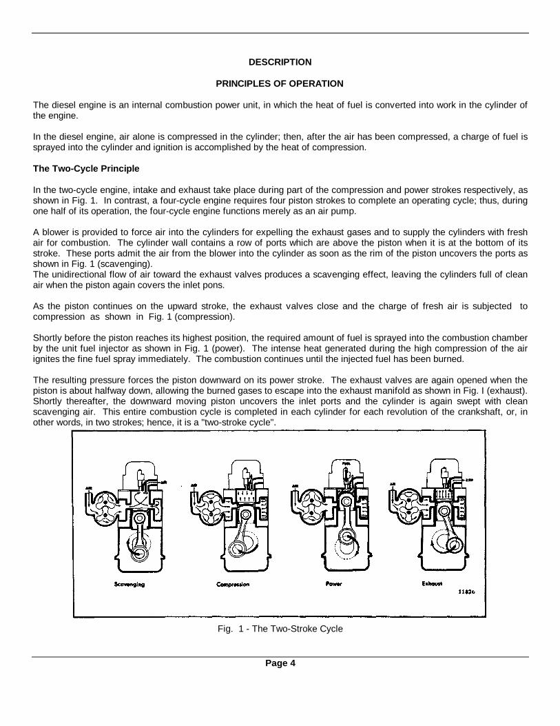
In the two-cycle engine, intake and exhaust take place during part of the compression and power strokes respectively, asshown in Fig. 1. In contrast, a four-cycle engine requires four piston strokes to complete an operating cycle; thus, duringone half of its operation, the four-cycle engine functions merely as an air pump.
A blower is provided to force air into the cylinders for expelling the exhaust gases and to supply the cylinders with freshair for combustion. The cylinder wall contains a row of ports which are above the piston when it is at the bottom of itsstroke. These ports admit the air from the blower into the cylinder as soon as the rim of the piston uncovers the ports asshown in Fig. 1 (scavenging).The unidirectional flow of air toward the exhaust valves produces a scavenging effect, leaving the cylinders full of cleanair when the piston again covers the inlet pons.
As the piston continues on the upward stroke, the exhaust valves close and the charge of fresh air is subjected tocompression as shown in Fig. 1 (compression).
Shortly before the piston reaches its highest position, the required amount of fuel is sprayed into the combustion chamberby the unit fuel injector as shown in Fig. 1 (power). The intense heat generated during the high compression of the airignites the fine fuel spray immediately. The combustion continues until the injected fuel has been burned.
The resulting pressure forces the piston downward on its power stroke. The exhaust valves are again opened when thepiston is about halfway down, allowing the burned gases to escape into the exhaust manifold as shown in Fig. I (exhaust).Shortly thereafter, the downward moving piston uncovers the inlet ports and the cylinder is again swept with cleanscavenging air. This entire combustion cycle is completed in each cylinder for each revolution of the crankshaft, or, inother words, in two strokes; hence, it is a "two-stroke cycle".
Fig. 1 - The Two-Stroke Cycle
Page 4
Description
GENERAL DESCRIPTION
The two-cycle diesel engines covered in this manual have the same bore and stroke and many of the major working partssuch as injectors, pistons, connecting rods, cylinder liners and other parts are interchangeable.
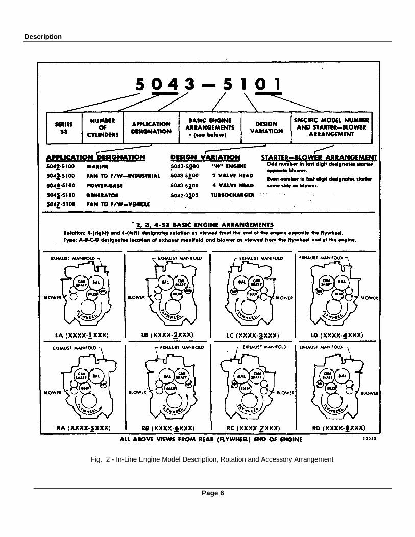
The In-line engines, including the inclined marine models, include standard accessories such as the blower, water pump,governor and fuel pump, which, on some models, may be located on either side of the engine regardless of the directionthe crankshaft rotates. Further flexibility in meeting installation requirements is achieved with the cylinder head whichcan be installed to accommodate the exhaust manifold on either side of the engine.
The V-type engine uses many In-line engine parts, including the 3-53 cylinder head. The blower is mounted on top of theengine between the two banks of cylinders and is driven by the gear train. The governor is mounted on the rear end ofthe 6V-53 blower.
The meaning of each digit in the model numbering system is shown in Figs. 2 and 3. The letter L or R indicates left orright-hand engine rotation as viewed from the front of the engine. The letter A,B,C or D designates the blower andexhaust manifold location on the In-line engines as viewed from the rear of the engine while the letter A or C designatesthe location of the oil cooler and starter on the 6V-53 engine.
Each engine is equipped with an oil cooler, replaceable element type lubricating oil filter, fuel oil strainer, fuel oil filter, anair cleaner or air silencer, a governor, a heat exchanger and raw water pump or a fan and radiator, and a starting motor.
Full pressure lubrication is supplied to all main bearings, connecting rod bearings, and camshaft bearings, and to othermoving parts.
Oil is drawn by suction from the oil pan through the intake screen and pipe to the oil pump where it is pressurized anddelivered to the oil filter and the oil cooler. From the oil cooler, the oil enters oil galleries in the cylinder block andcylinder head for distribution to the main bearings, connecting rod bearings, camshaft bearings, rocker arm mechanismand other functional parts.
The cooling system has a centrifugal water pump which circulates the engine coolant through the oil cooler and waterjackets. The engine temperature is regulated by a thermostat(s).
Fuel is drawn from the supply tank through the fuel strainer and enters a gear type fuel pump at the inlet side. Uponleaving the pump under pressure, the fuel is forced through the fuel filter into the inlet manifold where it passes throughfuel pipes into the inlet side of the fuel injectors. The fuel is filtered through elements in the injectors and then atomizedthrough small spray tip orifices into the combustion chamber. Excess fuel is returned to the fuel tank through the fueloutlet galleries and connecting lines.
Air for scavenging and combustion is supplied by a blower which pumps air into the engine cylinders via the air box andcylinder liner ports. All air entering the blower first passes through an air cleaner or air silencer.
The engine may be started by either a hydraulic or an electric starting system.
The engine speed is regulated by a mechanical or hydraulic type engine governor, depending upon the engineapplication.
Page 5
Description
Fig. 2 - In-Line Engine Model Description, Rotation and Accessory Arrangement
Page 6

Description
Fig. 3 · 6V Engine Model Description, Rotation and Accessory Arrangement
Page 7

Description
GENERAL SPECIFICATIONS
3-53 4-53 6V-53Type....................................................................................... 2 Cycle 2 Cycle 2 CycleNumber of cylinders ............................................................... 3 4 6Bore (inches) .......................................................................... 3.875 3.875 3.875Bore (mm).............................................................................. 98 98 98Stroke (inches) ....................................................................... 4.5 4.5 4.5Stroke (mm) ........................................................................... 114 114 114Compression Ratio (nominal)(standard engines)..................... 17 to 1 17 to 1 17 to 1Compression Ratio (nominal)("N" engines) ............................. 21 to 1 21 to 1 21 to 1Total Displacement - cubic inches .......................................... 159 212 318Total Displacement - litres ...................................................... 2.61 3.48 5.22Number of main bearings ....................................................... 4 5 4
Fig. 4. Series 53 Cylinder Arrangement
Page 8
Description
ENGINE MODEL AND SERIAL NUMBER DESIGNATION
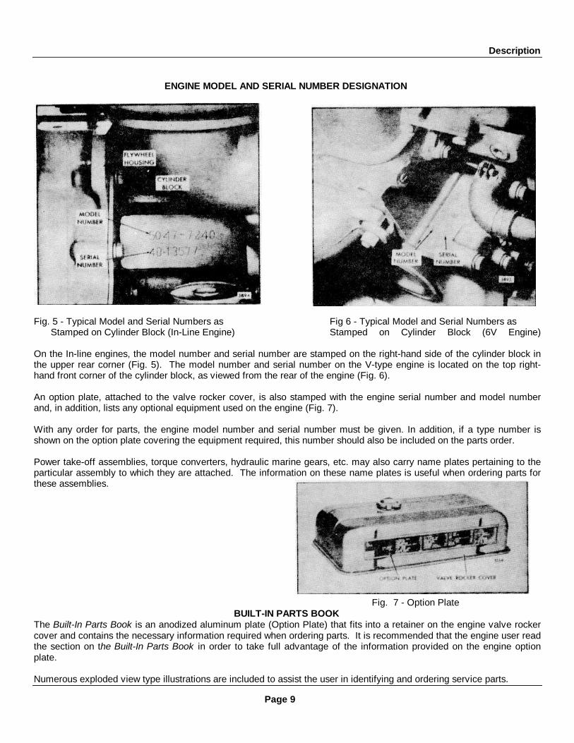
Fig. 5 - Typical Model and Serial Numbers as Fig 6 - Typical Model and Serial Numbers asStamped on Cylinder Block (In-Line Engine) Stamped on Cylinder Block (6V Engine)
On the In-line engines, the model number and serial number are stamped on the right-hand side of the cylinder block inthe upper rear corner (Fig. 5). The model number and serial number on the V-type engine is located on the top right-hand front corner of the cylinder block, as viewed from the rear of the engine (Fig. 6).
An option plate, attached to the valve rocker cover, is also stamped with the engine serial number and model numberand, in addition, lists any optional equipment used on the engine (Fig. 7).
With any order for parts, the engine model number and serial number must be given. In addition, if a type number isshown on the option plate covering the equipment required, this number should also be included on the parts order.
Power take-off assemblies, torque converters, hydraulic marine gears, etc. may also carry name plates pertaining to theparticular assembly to which they are attached. The information on these name plates is useful when ordering parts forthese assemblies.
Fig. 7 - Option PlateBUILT-IN PARTS BOOK
The Built-In Parts Book is an anodized aluminum plate (Option Plate) that fits into a retainer on the engine valve rockercover and contains the necessary information required when ordering parts. It is recommended that the engine user readthe section on the Built-In Parts Book in order to take full advantage of the information provided on the engine optionplate.
Numerous exploded view type illustrations are included to assist the user in identifying and ordering service parts.
Page 9
Description
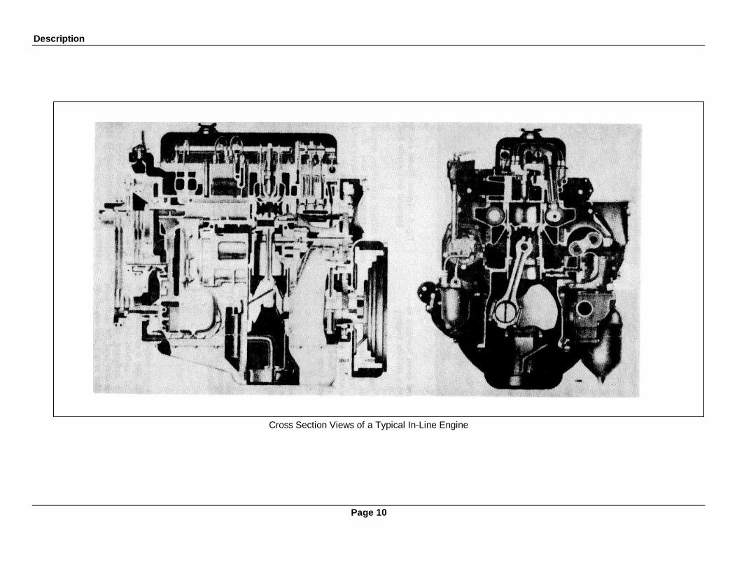
Cross Section Views of a Typical In-Line Engine
Page 10
Description
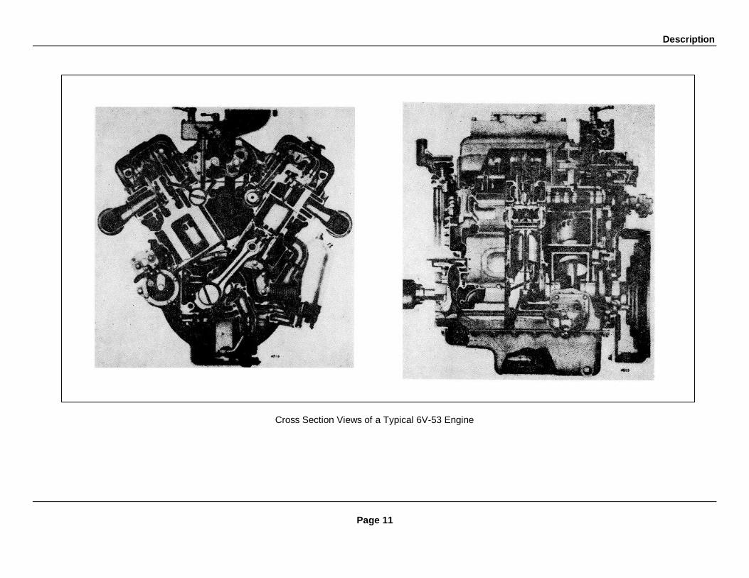
Cross Section Views of a Typical 6V-53 Engine
Page 11

ENGINE SYSTEMS
The Series 53 Detroit Diesel engines incorporate four basic systems which direct the flow of fuel, air, lubricating oil, andengine coolant.
A brief description of each of these systems and their components, and the necessary maintenance and adjustmentprocedures are given in this manual.
FUEL SYSTEM
The fuel system (Figs. I and 2) consists of the fuel injectors, fuel pipes, fuel manifolds (integral with the cylinder head),fuel pump, fuel strainer, fuel filter and the necessary connecting fuel lines.
On In-line engines, a restricted fitting is located in the cylinder head fuel return manifold outlet to maintain pressurewithin the fuel system. On V-type engines, this restricted fitting is located in the left-bank cylinder head.
Fuel is drawn from the supply tank through the fuel strainer and enters the fuel pump at the inlet side. Upon leaving thepump under pressure, the fuel is forced through the fuel filter and into the fuel inlet manifold where it passes through fuelpipes into the inlet side of each fuel injector. The fuel is filtered through elements in the injectors and atomizedthrough small spray tip orifices into the combustion chamber. Surplus fuel, returning from the injectors, passes throughthe fuel return manifold and connecting fuel lines back to the fuel tank.
The continuous flow of fuel through the injectors helps to cool the injectors and remove air from the fuel system.
A check valve may be installed between the fuel strainer and the source of supply as optional equipment to preventfuel drain back when the engine is not running.
Fuel InjectorThe fuel injector combines in a single unit all of the parts necessary to provide complete and independent fuel injection ateach cylinder. The injector creates the high pressure necessary for fuel injection, meters the proper amount of fuel,atomizes the fuel and times the injection into the combustion chamber.
Since the injector is one of the most important and carefully constructed parts of the engine, it is recommended that theengine operator replace the injector as an assembly if it is not operating properly. Authorized Detroit Diesel AllisonService Outlets are properly equipped to service injectors.
Fig. 1 - Schematic Diagram of Typical Fuel Fig. 2 - Schematic Diagram of Typical FuelSystem - In-Line Engine System - V-type Engine
Page 13
Engine Systems
Remove InjectorAn injector may be removed in the following manner:
1. Clean and remove the valve rocker cover.
2. Disconnect the fuel pipes from both the injector and the fuelconnectors.
3. Immediately after removing the fuel pipes, cover the injectorinlet and outlet fittings with shipping caps to prevent dirt fromentering.
4. Turn the crankshaft manually in the direction of enginerotation or crank the engine with the starting motor, if necessary,until the rocker arms for the particular cylinder are aligned in ahorizontal plane.
CAUTION: If a wrench is used on the crankshaft bolt atthe front of the engine, do not turn the crankshaft in aleft-hand direction of rotation as the bolt will beloosened. Remove the starting motor and use a prybar against the teeth of the flywheel ring gear to turnthe crankshaft.
5. Remove the two rocker shaft bracket bolts and swing therocker arm assembly away from the injector and valves.
6. Remove the injector clamp bolt, washer and clamp.
7. Loosen the inner and outer adjusting screws on the injector rack control lever and slide the lever away from theinjector.
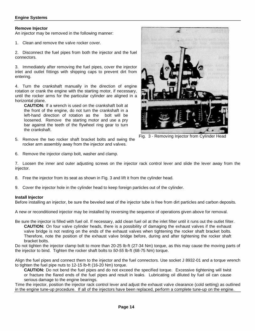
8. Free the injector from its seat as shown in Fig. 3 and lift it from the cylinder head.
9. Cover the injector hole in the cylinder head to keep foreign particles out of the cylinder.
Install InjectorBefore installing an injector, be sure the beveled seat of the injector tube is free from dirt particles and carbon deposits.
A new or reconditioned injector may be installed by reversing the sequence of operations given above for removal.
Be sure the injector is filled with fuel oil. If necessary, add clean fuel oil at the inlet filter until it runs out the outlet filter.CAUTION: On four valve cylinder heads, there is a possibility of damaging the exhaust valves if the exhaustvalve bridge is not resting on the ends of the exhaust valves when tightening the rocker shaft bracket bolts.Therefore, note the position of the exhaust valve bridge before, during and after tightening the rocker shaftbracket bolts.
Do not tighten the injector clamp bolt to more than 20-25 lb-ft (27-34 Nm) torque, as this may cause the moving parts ofthe injector to bind. Tighten the rocker shaft bolts to 50-55 lb-ft (68-75 Nm) torque.
Align the fuel pipes and connect them to the injector and the fuel connectors. Use socket J 8932-01 and a torque wrenchto tighten the fuel pipe nuts to 12-15 lb-ft (16-20 Nm) torque.
CAUTION: Do not bend the fuel pipes and do not exceed the specified torque. Excessive tightening will twistor fracture the flared ends of the fuel pipes and result in leaks. Lubricating oil diluted by fuel oil can causeserious damage to the engine bearings.
Time the injector, position the injector rack control lever and adjust the exhaust valve clearance (cold setting) as outlinedin the engine tune-up procedure. If all of the injectors have been replaced, perform a complete tune-up on the engine.
Fig. 3 - Removing Injector from Cylinder Head
Page 14

Engine SystemsFuel Pump
A positive displacement gear-type fuel pump is attached to thegovernor or blower on the In-line engines and to the flywheelhousing on the V-type engines.
A spring-loaded relief valve, incorporated in the pump body,normally remains in the closed position, operating only when thepressure on the outlet side (to the fuel filter) becomes excessivedue to a plugged filter or fuel line.
The fuel pump incorporates two oil seals. Two tapped holes areprovided in the underside of the pump body, between the oilseals, to permit a drain tube to be attached. If fuel leakageexceeds one drop per minute, the seals must be replaced. Anauthorized Detroit Diesel Allison Service Outlet is properlyequipped to replace the seals.
Fuel pumps are furnished in either left or right-hand rotation,according to the engine model, and are stamped RH or LH.These pumps are not interchangeable and cannot be rebuilt tooperate in an opposite rotation.
Fuel Strainer and Fuel Filter
A replaceable-element type fuel strainer and fuel filter (Fig. 4)are used in the fuel system to remove impurities from the fuel.The strainer removes the larger particles and the filter removesthe small foreign particles.
The fuel strainer and fuel filter are basically identical inconstruction, both consisting of a cover, shell and replaceableelement. Since the fuel strainer is placed between the fuel supplytank and the fuel pump, it functions under suction; the fuel filter,which is installed between the fuel pump and the fuel inletmanifold in the cylinder head, operates under pressure.
Replace the elements as follows:
1. With the engine shut down, place a suitable container under the fuel strainer or filter and open the drain cock. Thefuel will drain more freely if the cover nut is loosened slightly.
2. Support the shell, unscrew the cover nut and remove the shell and element.
3. Remove and discard the element and gasket. Clean the shell with fuel oil and dry it with a cloth or compressed air.
4. Place a new element, which has been thoroughly soaked in clean fuel oil, over the stud and push it down on the seat.Close the drain cock and fill the shell approximately two-thirds full with clean fuel oil.
5. Affix a new shell gasket, place the shell and element into position under the cover and start the cover nut on the shellstud.
6. Tighten the cover nut only enough to prevent fuel leakage.
7. Remove the plug in the strainer or filter cover and fill the shell with fuel. Fuel system primer J 5956 may be used toprime the fuel system.
8. Start and operate the engine and check the fuel system for leaks.Spin-On Type Fuel FilterA spin-on fuel strainer and fuel filter (Fig. 5) is used on certain engines. The spin-on filter cartridge consists of a shell,element and gasket combined into a unitized replacement assembly. No separate springs or seats are required tosupport the filters.
Page 15
Fig. 4 - Typical Fuel Strainer and Filter Mounting

Engine Systems
The filter covers incorporate a threaded sleeve to accept the spin-onfilter cartridges. The word "Primary" is cast on the fuel strainer coverand the word "Secondary" is cast on the fuel filter cover for identification.No drain cocks are provided on the spin-on filters. Where water is aproblem, it is recommended that a water separator be installed.Otherwise, residue may be drained by removing and inverting the filter.Refill the filter with clean fuel oil before reinstalling it.A 1" diameter twelve-point nut on the bottom of the filter is provided tofacilitate removal and installation.
Replace the filter as follows:
1. Unscrew the filter (or strainer) and discard it.
2. Fill a new filter replacement cartridge about two-thirds full with cleanfuel oil. Coat the seal gasket lightly with clean fuel oil.
3. Install the new filter assembly and tighten it to two-thirds of a turnbeyond gasket contact.
4. Start the engine and check for leaks.
Fuel TankRefill the fuel tank at the end of each day's operation to preventcondensation from contaminating the fuel.
CAUTION: A galvanized steel tank should never be used for fuel storage because the fuel oilreacts chemically with the zinc coating to form powdery flakes which quickly clog the fuel strainerand filter and damage the fuel pump and the fuel injectors.
Engine Out of FuelThe problem in restarting the engine after it has run out of fuel stems from the fact that after the fuel is exhausted fromthe fuel tank, fuel is then pumped from the primary fuel strainer and sometimes partially removed from the secondaryfuel filter before the fuel supply becomes insufficient to sustain engine firing. Consequently, these components must berefilled with fuel and the fuel pipes rid of air in order for the system to provide adequate fuel for the injectors.When an engine has run out of fuel, there is a definite procedure to follow for restarting the engine.
1. Fill the fuel tank with the recommended grade of fuel oil. If only partial filling of the tank is possible, add a minimumof ten gallons (38 litres) of fuel.
2. Remove the fuel strainer shell and element from the strainer cover and fill the shell with fuel oil. Install the shell andelement.
3. Remove and fill the fuel filter shell and element with fuel oil as in Step 2.
4. Start the engine. Check the filter and strainer for leaks.
NOTE: In some instances, it may be necessary to remove a valve rocker cover and loosen afuel pipe nut in order to bleed trapped air from the fuel system. Be sure the fuel pipe isretightened securely before replacing the rocker cover.
Primer J 5956 may be used to prime the entire fuel system. Remove the filler plug in the fuel filter cover and install theprimer. Prime the system. Remove the primer and install the filler plug.
Page 16
Fig. 5 - Typical Spin-On Type Fuel Strainerand Fuel Filter Mounting
Engine Systems
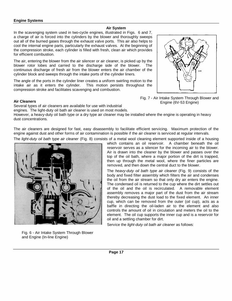
Air SystemIn the scavenging system used in two-cycle engines, illustrated in Figs. 6 and 7,a charge of air is forced into the cylinders by the blower and thoroughly sweepsout all of the burned gases through the exhaust valve ports. This air also helps tocool the internal engine parts, particularly the exhaust valves. At the beginning ofthe compression stroke, each cylinder is filled with fresh, clean air which providesfor efficient combustion.
The air, entering the blower from the air silencer or air cleaner, is picked up by theblower rotor lobes and carried to the discharge side of the blower. Thecontinuous discharge of fresh air from the blower enters the air chamber of thecylinder block and sweeps through the intake ports of the cylinder liners.
The angle of the ports in the cylinder liner creates a uniform swirling motion to theintake air as it enters the cylinder. This motion persists throughout thecompression stroke and facilitates scavenging and combustion.
Air CleanersSeveral types of air cleaners are available for use with industrialengines. The light-duty oil bath air cleaner is used on most models.However, a heavy-duty oil bath type or a dry type air cleaner may be installed where the engine is operating in heavydust concentrations.
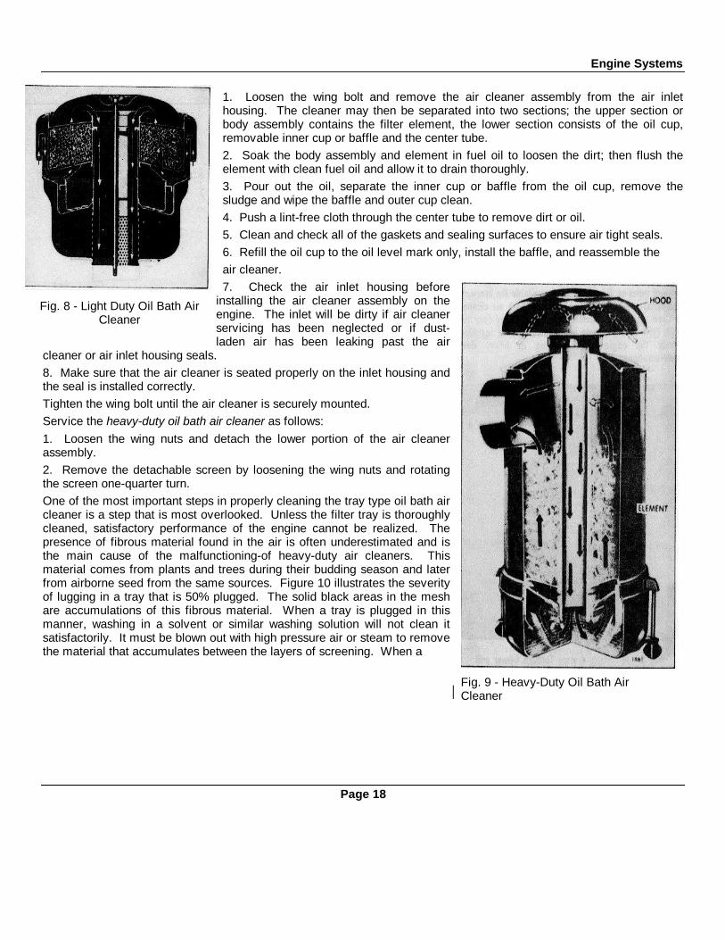
The air cleaners are designed for fast, easy disassembly to facilitate efficient servicing. Maximum protection of theengine against dust and other forms of air contamination is possible if the air cleaner is serviced at regular intervals.The light-duty oil bath type air cleaner (Fig. 8) consists of a metal wool cleaning element supported inside of a housing
which contains an oil reservoir. A chamber beneath the oilreservoir serves as a silencer for the incoming air to the blower.Air is drawn into the cleaner by the blower and passes over thetop of the oil bath, where a major portion of the dirt is trapped,then up through the metal wool, where the finer particles areremoved, and then down the central duct to the blower.The heavy-duty oil bath type air cleaner (Fig. 9) consists of thebody and fixed filter assembly which filters the air and condensesthe oil from the air stream so that only dry air enters the engine.The condensed oil is returned to the cup where the dirt settles outof the oil and the oil is recirculated. A removable elementassembly removes a major part of the dust from the air streamthereby decreasing the dust load to the fixed element. An innercup, which can be removed from the outer (oil cup), acts as abaffle in directing the oil-laden air to the element and alsocontrols the amount of oil in circulation and meters the oil to theelement. The oil cup supports the inner cup and is a reservoir foroil and a settling chamber for dirt.Service the light-duty oil bath air cleaner as follows:
Page 17
Fig. 7 - Air Intake System Through Blower andEngine (6V-53 Engine)
Fig. 6 - Air Intake System Through Blowerand Engine (In-line Engine)
Engine Systems
1. Loosen the wing bolt and remove the air cleaner assembly from the air inlethousing. The cleaner may then be separated into two sections; the upper section orbody assembly contains the filter element, the lower section consists of the oil cup,removable inner cup or baffle and the center tube.2. Soak the body assembly and element in fuel oil to loosen the dirt; then flush theelement with clean fuel oil and allow it to drain thoroughly.3. Pour out the oil, separate the inner cup or baffle from the oil cup, remove thesludge and wipe the baffle and outer cup clean.4. Push a lint-free cloth through the center tube to remove dirt or oil.5. Clean and check all of the gaskets and sealing surfaces to ensure air tight seals.6. Refill the oil cup to the oil level mark only, install the baffle, and reassemble theair cleaner.7. Check the air inlet housing before
installing the air cleaner assembly on theengine. The inlet will be dirty if air cleanerservicing has been neglected or if dust-laden air has been leaking past the air
cleaner or air inlet housing seals.8. Make sure that the air cleaner is seated properly on the inlet housing andthe seal is installed correctly.Tighten the wing bolt until the air cleaner is securely mounted.Service the heavy-duty oil bath air cleaner as follows:1. Loosen the wing nuts and detach the lower portion of the air cleanerassembly.2. Remove the detachable screen by loosening the wing nuts and rotatingthe screen one-quarter turn.One of the most important steps in properly cleaning the tray type oil bath aircleaner is a step that is most overlooked. Unless the filter tray is thoroughlycleaned, satisfactory performance of the engine cannot be realized. Thepresence of fibrous material found in the air is often underestimated and isthe main cause of the malfunctioning-of heavy-duty air cleaners. Thismaterial comes from plants and trees during their budding season and laterfrom airborne seed from the same sources. Figure 10 illustrates the severityof lugging in a tray that is 50% plugged. The solid black areas in the meshare accumulations of this fibrous material. When a tray is plugged in thismanner, washing in a solvent or similar washing solution will not clean itsatisfactorily. It must be blown out with high pressure air or steam to removethe material that accumulates between the layers of screening. When a
Page 18
Fig. 8 - Light Duty Oil Bath AirCleaner
Fig. 9 - Heavy-Duty Oil Bath AirCleaner
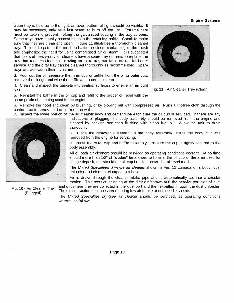
Engine Systemsclean tray is held up to the light, an even pattern of light should be visible. Itmay be necessary, only as a last resort, to burn off the lint. Extreme caremust be taken to prevent melting the galvanized coating in the tray screens.Some trays have equally spaced holes in the retaining baffle. Check to makesure that they are clean and open. Figure 11 illustrates a thoroughly cleanedtray. The dark spots in the mesh indicate the close overlapping of the meshand emphasize the need for using compressed air or steam. It is suggestedthat users of heavy-duty air cleaners have a spare tray on hand to replace thetray that requires cleaning. Having an extra tray available makes for betterservice and the dirty tray can be cleaned thoroughly as recommended. Sparetrays are well worth their investment.3. Pour out the oil, separate the inner cup or baffle from the oil or outer cup,remove the sludge and wipe the baffle and outer cup clean.4. Clean and inspect the gaskets and sealing surfaces to ensure an air tightseal.5. Reinstall the baffle in the oil cup and refill to the proper oil level with thesame grade of oil being used in the engine.6. Remove the hood and clean by brushing, or by blowing out with compressed air. Push a lint-free cloth through thecenter tube to remove dirt or oil from the walls.7. Inspect the lower portion of the air cleaner body and center tube each time the oil cup is serviced. If there are any
indications of plugging, the body assembly should be removed from the engine andcleaned by soaking and then flushing with clean fuel oil. Allow the unit to drainthoroughly.8. Place the removable element in the body assembly. Install the body if it wasremoved from the engine for servicing.9. Install the outer cup and baffle assembly. Be sure the cup is tightly secured to thebody assembly.All oil bath air cleaners should be serviced as operating conditions warrant. At no timeshould more than 1/2" of "sludge" be allowed to form in the oil cup or the area used forsludge deposit, nor should the oil cup be filled above the oil level mark.The United Specialties dry-type air cleaner shown in Fig. 12 consists of a body, dustunloader and element clamped to a base.Air is drawn through the cleaner intake pipe and is automatically set into a circularmotion. This positive spinning of the dirty air "throws out" the heavier particles of dust
and dirt where they are collected in the dust port and then expelled through the dust unloader.The circular action continues even during low air intake at engine idle speeds.The United Specialties dry-type air cleaner should be serviced, as operating conditionswarrant, as follows:
Page 19
Fig; 11 - Air Cleaner Tray (Clean)
Fig. 10 - Air Cleaner Tray(Plugged)
Engine Systems
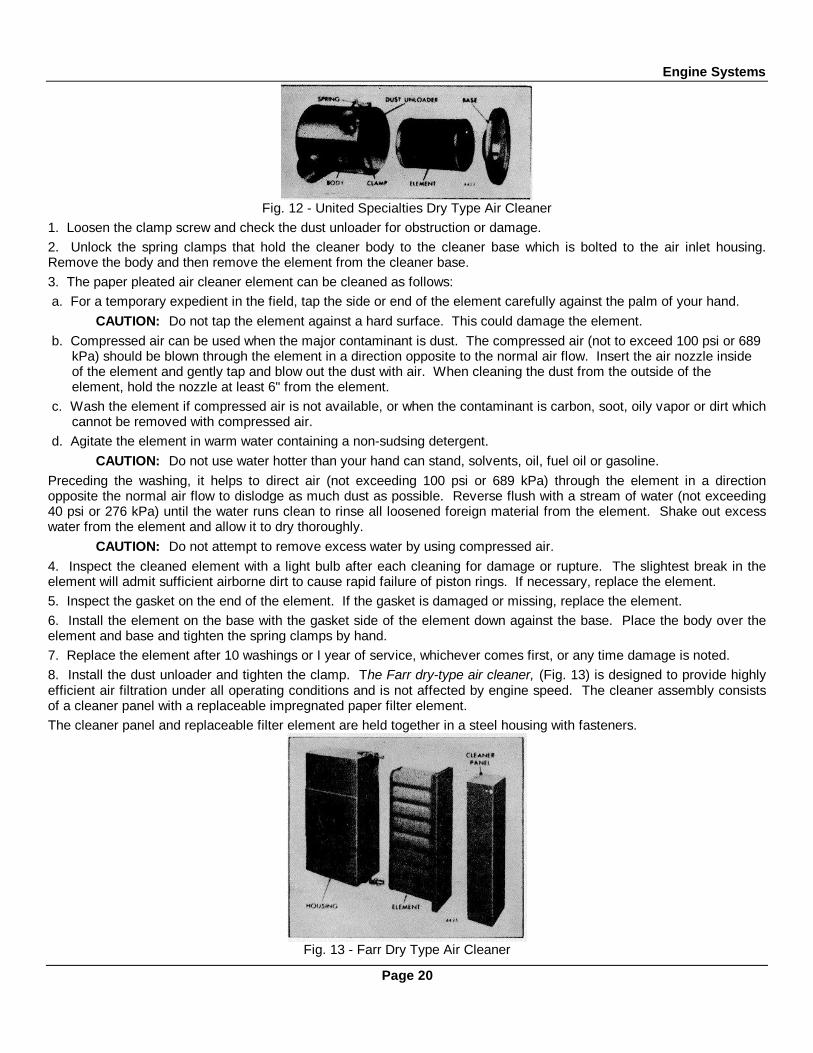
Fig. 12 - United Specialties Dry Type Air Cleaner1. Loosen the clamp screw and check the dust unloader for obstruction or damage.2. Unlock the spring clamps that hold the cleaner body to the cleaner base which is bolted to the air inlet housing.Remove the body and then remove the element from the cleaner base.3. The paper pleated air cleaner element can be cleaned as follows: a. For a temporary expedient in the field, tap the side or end of the element carefully against the palm of your hand.
CAUTION: Do not tap the element against a hard surface. This could damage the element. b. Compressed air can be used when the major contaminant is dust. The compressed air (not to exceed 100 psi or 689
kPa) should be blown through the element in a direction opposite to the normal air flow. Insert the air nozzle inside of the element and gently tap and blow out the dust with air. When cleaning the dust from the outside of the element, hold the nozzle at least 6" from the element.
c. Wash the element if compressed air is not available, or when the contaminant is carbon, soot, oily vapor or dirt whichcannot be removed with compressed air.
d. Agitate the element in warm water containing a non-sudsing detergent.CAUTION: Do not use water hotter than your hand can stand, solvents, oil, fuel oil or gasoline.
Preceding the washing, it helps to direct air (not exceeding 100 psi or 689 kPa) through the element in a directionopposite the normal air flow to dislodge as much dust as possible. Reverse flush with a stream of water (not exceeding40 psi or 276 kPa) until the water runs clean to rinse all loosened foreign material from the element. Shake out excesswater from the element and allow it to dry thoroughly.
CAUTION: Do not attempt to remove excess water by using compressed air.4. Inspect the cleaned element with a light bulb after each cleaning for damage or rupture. The slightest break in theelement will admit sufficient airborne dirt to cause rapid failure of piston rings. If necessary, replace the element.5. Inspect the gasket on the end of the element. If the gasket is damaged or missing, replace the element.6. Install the element on the base with the gasket side of the element down against the base. Place the body over theelement and base and tighten the spring clamps by hand.7. Replace the element after 10 washings or I year of service, whichever comes first, or any time damage is noted.8. Install the dust unloader and tighten the clamp. The Farr dry-type air cleaner, (Fig. 13) is designed to provide highlyefficient air filtration under all operating conditions and is not affected by engine speed. The cleaner assembly consistsof a cleaner panel with a replaceable impregnated paper filter element.The cleaner panel and replaceable filter element are held together in a steel housing with fasteners.
Fig. 13 - Farr Dry Type Air Cleaner
Page 20

Engine SystemsThe deflector vanes impart a swirling motion to the air entering the air cleaner and centrifuge the dust particles againstthe walls of the tubes. The dust particles are then carried to the dust bin at the bottom of the cleaner by approximately10% bleed-off air and are finally discharged into the atmosphere. The cleaner panel is fully effective at either high or lowvelocities.The remainder of the air in the cleaner reverses direction and spirals back along the discharge tubes again centrifugingthe air. The filtered air then reverses direction again and enters the replaceable filter element through the center portionof the discharge tubes. The air is filtered once more as it passes through the pleats of the impregnated paper elementbefore leaving the outlet port of the cleaner housing.The cleaner panel tends to be self-cleaning. However, it should be inspected and any accumulated foreign materialremoved during the periodic replacement of the impregnated paper filter element. Overloading of the paper element willnot cause dirt particles to by-pass the filter and enter the engine, but will result in starving the engine for air.The filter element should be replaced, as operating conditions warrant, as follows:1. Loosen the wing nuts on the fasteners and swing the retaining bolts away from the cleaner panel.2. Lift the cleaner panel away from the housing and inspect it. Clean out any accumulated foreign material.3. Withdraw the paper filter element and discard it.4. Install a new filter element.5. Install the cleaner panel aid secure it in place with the fasteners.Air SilencerThe air silencer, used on some marine engines, is bolted to the intake side of the blower housing. The silencer has aperforated steel partition welded in place parallel with the outside faces, enclosing flame-proof, felted cotton waste whichserves as a silencer for air entering the blower.While no servicing is required on the air silencer proper, it may be removed when necessary to replace the air inletscreen. This screen is used to filter out any large foreign particles which might seriously damage the blower assembly.Air Box DrainsDuring normal engine operation, water vapor from the air charge, as well as a slight amount of fuel and lubricating oilfumes, condenses and settles on the bottom of the air box. This condensation is removed by the air box pressurethrough air box drain tubes mounted on the side of the cylinder block.The air box drains must be open at all times. With the engine running, a periodic check is recommended for air flowfrom the air box drain tubes. Liquid accumulation on the bottom of the air box indicates a drain tube may be plugged.Such accumulations can be seen by removing the cylinder block air box cover(s) and should be wiped out with rags orblown out with compressed air. Then remove the drain tubes and connectors from the cylinder block and clean themthoroughly.Some engines are equipped with an air box drain check valve. Refer to the Lubrication and PreventiveMaintenance section of this manual for service instructions.Crankcase VentilationHarmful vapors which may form within the engine are removed from the crankcase, gear train and valve compartment bya continuous, pressurized ventilation system.A slight pressure is maintained within the engine crankcase by the seepage of a small amount of air from the airbox pastthe piston rings. This air sweeps up through the engine and is drawn off through a crankcase breather.In-line engines are equipped with a breather assembly which is mounted on the rocker cover or the flywheel housing.The 6V engines incorporate a breather assembly mounted inside of the upper engine front cover.The wire mesh pad (element) in the breather assemblies should be cleaned if excessive crankcase pressure is observed.If it is necessary to clean the element, remove the breather housing from the flywheel housing (In-line engines) and theupper engine front cover (6V engines). Wash the element in fuel oil and dry it with compressed air. Reinstall theelement and the breather assembly.
Page 21

Engine Systems
LUBRICATING SYSTEM
Fig. 14 - Typical In-Line Engine Oil Filter Mounting Fig. 15 - Typical V-Type Engine Oil Filter Mounting
The Series 53 engine lubricating system, illustrated in Figs. 16 and 17, includes an oil intake screen and tube assembly,an oil pump, a pressure regulator, a full-flow oil filter or by-pass filter with by-pass valve, and an oil cooler with a by-passvalve.Lubricating oil from the pump passes from the lower front cover through short oil galleries in the cylinder block. From theblock, the oil flows to the full-flow oil filter, then through the oil cooler (if used) and back into the front engine cover andcylinder block oil galleries for distribution to the various engine bearings. The drains from the cylinder head(s) and otherengine parts lead back to the oil pan.Oil pressure is regulated by a pressure relief valve mounted in the engine front cover. Oil cooler and oil filter by-passvalves prevent the stoppage of oil flow if these items become plugged.Oil FiltersEach engine is equipped with a full-flow type lubricating oil filter (Figs. 14 and 15). If additional filtering is required, a by-pass type oil filter may also be installed.All of the oil supplied to the engine passes through the full-flow filter that removes the larger foreign particles withoutrestricting the normal flow of oil.The by-pass filter assembly, when used, continually filters a portion of the lubricating oil that is being bled off the oilgallery when the engine is running. Eventually all of the oil passes through the filter, filtering out minute foreign particlesthat may be present.The lubricating oil filter elements should be replaced, each time the engine oil is changed, as follows:1. Remove the drain plug and drain the oil.2. The filter shell, element and stud may be detached as an assembly, after removing the center stud from the base.Discard the gasket.3. Clean the filter base.4. Discard the used element, wipe out the filter shell and install a new element on the center stud.5. Place a new gasket in the filter base, position the shell and element assembly on the gasket and tighten the centerstud carefully to prevent damaging the gasket or center stud.6. Install the drain plug and, after the engine is started, check for oil leaks.
Page 22

Engine Systems
Fig. 16 - Schematic Diagram of Typical In-Line Engine Lubricating System
Page 23

Engine Systems
Fig. 17 - Schematic Diagram of Typical 6V Engine Lubricating System
Page 24

Engine SystemsCOOLING SYSTEM
One of three different types of cooling systems is used on a Series 53 engine: radiator and fan, heat exchanger and rawwater pump, or keel cooling. A centrifugal type water pump is used to circulate the engine coolant in each system. Eachsystem incorporates thermostats to maintain a normal operating temperature of 160-185°F (71-85°C). Typical enginecooling system- are shown in Figs. 18 and 19.
Radiator Cooling System
The engine coolant is drawn from the bottom of the radiator core by the water pump and is forced through the oil coolerand into the cylinder block. The coolant circulates up through the cylinder block into the cylinder head, then to the watermanifold and thermostat housing. From the thermostat housing, the coolant returns to the radiator where it passes downa series of tubes and is cooled by the air stream created by the fan.
When starting a cold engine or when the coolant is below operating temperature, the coolant is restricted at thethermostat housing(s) and a by-pass provides water- circulation within the engine during the warm-up period.
Heat Exchanger Cooling System
In the heat exchanger cooling system, the coolant is drawn by the circulating pump from the bottom of the expansiontank through the engine oil cooler, then through the engine the same as in the radiator and fan system. Upon leavingthe thermostat housing, the coolant either passes through the heat exchanger core
Fig. 18 • Typical Cooling System for In-Line Engines
Page 25
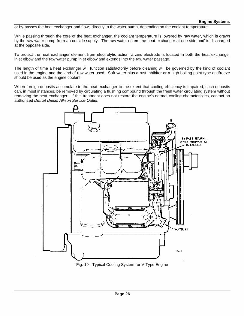
Engine Systemsor by-passes the heat exchanger and flows directly to the water pump, depending on the coolant temperature.
While passing through the core of the heat exchanger, the coolant temperature is lowered by raw water, which is drawnby the raw water pump from an outside supply. The raw water enters the heat exchanger at one side and' is dischargedat the opposite side.
To protect the heat exchanger element from electrolytic action, a zinc electrode is located in both the heat exchangerinlet elbow and the raw water pump inlet elbow and extends into the raw water passage.
The length of time a heat exchanger will function satisfactorily before cleaning will be governed by the kind of coolantused in the engine and the kind of raw water used. Soft water plus a rust inhibitor or a high boiling point type antifreezeshould be used as the engine coolant.
When foreign deposits accumulate in the heat exchanger to the extent that cooling efficiency is impaired, such depositscan, in most instances, be removed by circulating a flushing compound through the fresh water circulating system withoutremoving the heat exchanger. If this treatment does not restore the engine's normal cooling characteristics, contact anauthorized Detroit Diesel Allison Service Outlet.
Fig. 19 - Typical Cooling System for V-Type Engine
Page 26
Engine SystemsKeel Cooling SystemThe keel cooling system is similar to the heat exchanger system, except that the coolant temperature is reduced in thekeel cooler. In this system, the coolant is drawn by the circulating pump from the bottom of the expansion tank throughthe engine oil cooler. From the cooler the flow is the same as in the other systems. Upon leaving the thermostathousing, the coolant is by-passed directly to the bottom of the expansion tank until the engine operating temperature,controlled by the thermostat, is reached. As the engine temperature increases, the coolant is directed to the keel cooler,where the temperature of the coolant is reduced before flowing back to the expansion tank.
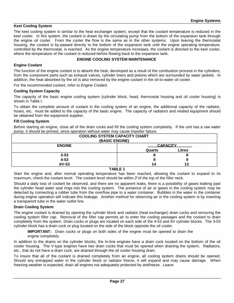
ENGINE COOLING SYSTEM MAINTENANCEEngine CoolantThe function of the engine coolant is to absorb the heat, developed as a result of the combustion process in the cylinders,from the component parts such as exhaust valves, cylinder liners and pistons which are surrounded by water jackets. Inaddition, the heat absorbed by the oil is also removed by the engine coolant in the oil-to-water oil cooler.For the recommended coolant, refer to Engine Coolant.Cooling System CapacityThe capacity of the basic engine cooling system (cylinder block, head, thermostat housing and oil cooler housing) isshown in Table I.To obtain the complete amount of coolant in the cooling system of an engine, the additional capacity of the radiator,hoses, etc. must be added to the capacity of the basic engine. The capacity of radiators and related equipment shouldbe obtained from the equipment supplier.Fill Cooling SystemBefore starting an engine, close all of the drain cocks and fill the cooling system completely. If the unit has a raw waterpump, it should be primed, since operation without water may cause impeller failure.
COOLING SYSTEM CAPACITY CHART(BASIC ENGINE)
ENGINE CAPACITYQuarts Litres
3-534-53
6V-53
8 89 9
14 13TABLE 1
Start the engine and, after normal operating temperature has been reached, allowing the coolant to expand to itsmaximum, check the coolant level. The coolant level should be within 2"of the top of the filler neck.Should a daily loss of coolant be observed, and there are no apparent leaks, there is a possibility of gases leaking pastthe cylinder head water seal rings into the cooling system. The presence of air or gases in the cooling system may bedetected by connecting a rubber tube from the overflow pipe to a water container. Bubbles in the water in the containerduring engine operation will indicate this leakage. Another method for observing air in the cooling system is by insertinga transparent tube in the water outlet line.Drain Cooling SystemThe engine coolant is drained by opening the cylinder block and radiator (heat exchanger) drain cocks and removing thecooling system filler cap. Removal of the filler cap permits air to enter the cooling passages and the coolant to draincompletely from the system. Drain cocks or plugs are located on each side of the 4-53 and 6V cylinder blocks. The 3-53cylinder block has a drain cock or plug located on the side of the block opposite the oil cooler.
IMPORTANT: Drain cocks or plugs on both sides of the engine must be opened to drain theengine completely.
In addition to the drains on the cylinder blocks, the In-line engines have a drain cock located on the bottom of the oilcooler housing. The V-type engines have two drain cocks that must be opened when draining the system. Radiators,etc., that do not have a drain cock, are drained through the oil cooler housing drain.To insure that all of the coolant is drained completely from an engine, all cooling system drains should be opened.Should any entrapped water in the cylinder block or radiator freeze, it will expand and may cause damage. Whenfreezing weather is expected, drain all engines not adequately protected by antifreeze. Leave
Page 27

Engine Systems
all of the drain cocks open until refilling the cooling system.The exhaust manifolds of marine engines are cooled by the same coolant used in the engine. Whenever the enginecooling system is drained, each exhaust manifold drain cock, located on the bottom near the exhaust outlet, must beopened. Raw water pumps are drained by loosening the cover attaching screws. It may be necessary to tap the rawwater pump cover gently to loosen it. After the water has been removed, tighten the screws.FlushingThe cooling system should be flushed each spring and fall. The flushing operation cleans the system of antifreezesolution in the spring and removes the summer rust inhibitor in the fall, preparing the cooling system for a new solution.The flushing operation should be performed as follows:1. Drain the previous season's solution from the engine.2. Refill the cooling system with soft clean water. If the engine is hot, fill slowly to prevent rapid cooling and distortion ofthe engine castings.3. Start the engine and operate it for 15 minutes to circulate the water thoroughly.4. Drain the cooling system completely.5. Refill the system with the solution required for the coming season.Cooling System CleanersIf the engine overheats and the fan belt tension and water level are satisfactory, clean and flush the entire coolingsystem. Remove scale formation by using a quality de-scaling solvent. Immediately after using the solvent, neutralizethe system with the neutralizer. It is important that the directions printed on the container of the de-scaling solvent bethoroughly read and followed.After the solvent and neutralizer have been used, completely drain the engine and radiator and reverse-flush beforefilling the cooling system.Reverse-Flushing
After the engine and radiator have been thoroughly cleaned, they should be reverse-flushed. The water pump should beremoved and the radiator and engine reverse-flushed separately to prevent dirt and scale deposits clogging the radiatortubes or being forced through the pump. Reverse-flushing is accomplished by hot water, under air pressure, being forcedthrough the cooling system in a direction opposite to the normal flow of coolant, loosening and forcing scale deposits out.The radiator is reverse-flushed as follows:1. Remove the radiator inlet and outlet hoses and replace the radiator cap.2. Attach a hose at the top of the radiator to lead water away from the engine.3. Attach a hose to the bottom of the radiator and insert a flushing gun in the hose.4. Connect the water hose of the gun to the water outlet and the air hose to the compressed air outlet.5. Turn on the water and, when the radiator is full, turn on the air in short blasts, allowing the radiator to fill between airblasts.
CAUTION: Apply air gradually. Do not exert more than 30 psi (207 kPa) air pressure. Toogreat a pressure may rupture a radiator tube.
6. Continue flushing until only clean water is expelled from the radiator.The cylinder block and cylinder head water passages re reverse-flushed as follows:1. Remove the thermostat and the water pump.2. Attach a hose to the water inlet of the cylinder block to drain the water away from the engine.3. Attach a hose to the water outlet at the top of the cylinder block and insert the flushing gun in the hose.4. Turn on the water and, when the water jackets are filled, turn on the air in short blasts, allowing the engine to fill withwater between air blasts.5. Continue flushing until the water from the engine runs clean.If scale deposits in the radiator cannot be removed by chemical cleaners or reverse-flushing as outlined above, it may benecessary to remove the upper tank and rod out the individual radiator tubes with flat steel rods. Circulate water throughthe radiator core from the bottom to the top during this operation.
Page 28

Engine SystemsMiscellaneous Cooling System Checks
In addition to the above cleaning procedures, the other components of the cooling system should be checked periodicallyto keep the engine operating at peak efficiency. The thermostat and the radiator pressure cap should be checked andreplaced, if found defective. The cooling system hoses should be inspected and any hose that feels abnormally hard orsoft should be replaced immediately.
Also, check the hose clamps to make sure they are tight. All external leaks should be corrected as soon as detected.The fan belt must be adjusted to provide the proper tension, and the fan shroud must be tight against the radiator core toprevent re-circulation of air which may lower cooling efficiency.
Water Pump
A centrifugal-type water pump is mounted on top of the engine oil cooler housing, either on the right-hand or left-handside of the engine, depending upon the engine model and rotation. It circulates the coolant through the cooling system.The pump is belt driven, by either the camshaft or balance shaft (In-line engines) or by one of the camshafts (V-typeengines).
An impeller is pressed onto one end of the water pump shaft, and a water pump drive pulley is pressed onto the oppositeend. The pump shaft is supported on a sealed double-row combination radial and thrust ball bearing. Coolant isprevented from creeping along the shaft toward the bearing by a seal. The shaft and bearing constitute an assembly andare serviced as such, since the shaft serves as the inner race of the ballbearing.
The sealed water pump shaft ball bearing is filled with lubricant when assembled. No further lubrication is required.Contact an authorized Detroit Diesel Allison Service Outlet if more information is needed.
Raw Water Pump
The raw water pump (Figs. 20 and 21) is a positive displacement pump, used for circulating raw water through the heatexchanger to lower the temperature of the engine coolant. It is driven by a coupling from the end of the camshaft.
Seal failure is readily noticed by a flow of water visible at the openings in the raw water pump housing, located betweenthe pump mounting flange and the inlet and outlet ports. These openings must remain open at all times.
Fig. 20. - Raw Water Pump Used on In-Line Engine.
The impeller, cam and wear plate assembly, and water seal assembly may be serviced without removing the pump fromthe engine as outlined below.
1. Remove the cover and gasket.
2. Note the position of the impeller blades to aid in the reassembly. Then grasp a blade on each side of the impellerwith pliers and pull the impeller off of the shaft.
3. The neoprene spline seal(s) can be removed from the impeller by pushing a screw driver through the impeller fromthe open end.
Fig. 21. - Raw Water Pump Used on V-Type Engine.Page 29
Engine Systems
CAUTION: If the impeller is reuseable, exercise care to prevent damage to the splined surfaces.
4. Remove the cam retaining screw and withdraw the cam and wear plate assembly.
5. Remove the seal assembly from the pump used on a V-type engine by inserting two wires with hooked endsbetween the pump housing and seal with the hooks over the edge of the carbon seal. Remove the seal seat and gasketin the same way.
6. The seal may be removed from the pump used on the In-line engine by drilling two holes in the seal case andplacing metal screws in the holes so that they may be grasped and pulled with pliers. Then remove the rubber seal ring.
7. Clean and inspect the impeller, cam and wear plate assembly and water seal. The impeller must have a goodbond between the neoprene and the metal. If the impeller blades are damaged, worn or have taken a permanent set,replace the impeller. Reverse the wear plate if it is worn excessively and remove any burrs. Replace the seal, ifnecessary.
8. Install the seal assembly in the pump used on a V-type engine as follows:
a. If the seal seat and gasket were removed, place the gasket and seal seat over the shaft and press them intoposition in the seal cavity.
b. Place the seal ring securely in the ferrule, and with the carbon seal and washer correctly positioned against theferrule, slide the ferrule over the shaft and against the seal seat. Use care to ensure that the seal ring iscontained within the ferrule so that it grips the shaft.
c. Install the flat washer and then the marcel washer. A new seal may be installed in the pump used on the In-Line engine by placing the rubber seal ring in its groove, starting the seal (with the lip facing the impellercavity) over the shaft and tapping it into place against the seal spacer.
9. Install the cam and wear plate assembly.
NOTE: The wear plate is round and is doweled to the cam. The wear plate must be installed with the camin the pump housing as an assembly.
10. Apply a non-hardening sealant to the cam retaining screw and the hole in the pump body to prevent any leakage.Then hold the cam with the tapped hole aligned and secure it with the screw.
11. Compress the impeller blades to clear the off-set cam and press the impeller on the splined shaft. The blades mustbe correctly positioned to follow the direction of rotation.
12. Install the neoprene splined seal(s) in the bore of the impeller.
13. Turn the impeller several revolutions in the normal direction of rotation to position the blades.
14. Affix a new gasket and install the pump cover.
The Jabsco raw water pump is equipped with a synthetic rubber impeller. Since synthetic rubber loses its elasticity at lowtemperatures, impellers made of natural rubber should be installed when it is necessary to pump raw water that has atemperature below 40° F (4° C).
The natural rubber impeller can be identified by a stripe of green paint between two of the impeller blades.
Page 30

ENGINE EQUIPMENT
INSTRUMENT PANEL, INSTRUMENTS AND CONTROLS
The instruments (Fig. 1) generally required in the operation of a diesel engine consist of an oil pressure gage, a watertemperature gage, an ammeter and a mechanical tachometer. Also, closely related and usually installed in the generalvicinity of these instruments are certain controls consisting of an engine starter switch, an engine stop knob, anemergency stop knob and, on certain applications, the engine hand throttle.
Torqmatic converters are equipped with an oil pressure gage and, in some instances, an oil temperature gage. Theseinstruments are mounted on a separate panel.
Oil Pressure Gage
The oil pressure gage registers the pressure of the lubricating oil in the engine. As soon as the engine is started, the oilpressure gage should start to register. If the oil pressure gage does not register at least the minimum pressure listedunder Running in the Engine Operating Instructions, the engine should be stopped and the cause of low oil pressuredetermined and corrected before the engine is started again.
Water Temperature Gage
The engine coolant temperature is registered on the water temperature gage.
Fig. 1 - Typical Instrument PanelAmmeter
An ammeter is incorporated into the electrical circuit to show the current flow to and from the battery. After starting theengine, the ammeter should register a high charge rate at rated engine speed. This is the rate of charge received by thebattery to replenish the current used to start the engine. As the engine continues to operate, the ammeter should show adecline in charge rate to the battery. The ammeter will not show zero charge rate since the regulator voltage is sethigher than the battery voltage. The small current registered prevents rapid brush wear in the battery-charging alternator.If lights or other electrical equipment are connected into the circuit, the ammeter will show discharge when these itemsare operating or the engine speed is reduced.
Tachometer
The tachometer is driven by the engine and registers the speed of the engine in revolutions per minute (rpm).
Engine Starting Motor Switch
The starting switch is mounted on the instrument panel with the contact button extending through the front face of thepanel. The switch is used to energize the starting motor. As soon as the engine starts, release the switch.
Stop Knob
A stop knob is used on most applications to shut the engine down. When stopping an engine, the speed should bereduced to idle and the engine allowed to operate at idle for a few minutes to permit the coolant to reduce thetemperature of the engine's moving parts. Then the stop knob should be pulled and held until the engine stops. Pullingon the stop knob manually places the injector racks in the "no-fuel" position. The stop knob should be returned to itsoriginal position after the engine stops.
Emergency Stop Knob
In an emergency or if after pulling the stop knob, the engine continues to operate, the emergency stop knob
Page 31

Engine Equipment
may be pulled to stop the engine. The emergency stop knob, when pulled, will trip the air shut-off valve located betweenthe air inlet housing and the blower and shut off the air supply to the engine. Lack of air will prevent further combustionof the fuel and stop the engine.
The emergency stop knob must be pushed back in after the engine stops so the air shut-off valve can be opened forrestarting after the malfunction has been corrected.
Throttle Control
The engine throttle is connected to the governor speed control shaft through linkage. Movement of the speed controlshaft changes the speed setting of the governor and thus the engine speed.
Page 32

Engine Equipment
ENGINE PROTECTIVE SYSTEMS
MANUAL SHUT DOWN SYSTEM
The manually operated emergency engine shutdown device, mounted in the air inlet housing, is used to stop the enginein the event an abnormal condition should arise. If the. engine continues to run after the engine throttle is placed in theno fuel position, or if combustible liquids or gases are accidentally introduced into the combustion chamber causing over-speeding of the engine, the shutdown device will prevent damage to the engine by cutting off the air supply and thusstopping the engine.
The shutdown device consists of an air shut-off valve mounted in the air inlet housing which is retained in the openposition by a latch. A cable assembly is used to remotely trip the latch. Pulling the emergency shutdown knob all theway out will stop the engine. After the engine stops, the emergency shutdown knob must be pushed all the way in andthe air shut-off valve manually reset before the engine can be started again.
AUTOMATIC MECHANICAL SHUTDOWN SYSTEM
The automatic mechanical shutdown system illustrated in Fig. 2 is designed to stop the engine if there is a loss of oilpressure, loss of engine coolant, overheating of the engine coolant, or overspeeding of the engine. Engine oil pressure isutilized to activate the components of the system.
A coolant temperature-sensing valve and an adapter and copper plug assembly are mounted on the exhaust manifoldoutlet. The power element of the temperature-sensing valve is placed against one end of the copper plug, and the otherend of the plug extends into the exhaust manifold. Engine coolant is directed through the adapter and passes over thepower element of the valve. Engine oil, under pressure, is directed through a restricted fitting to the temperature-sensing valve and to an oil pressure actuated bellows located on the air inlet housing.
Fig. 2 - Mechanical Shutdown System Schematically Illustrated.
Page 33
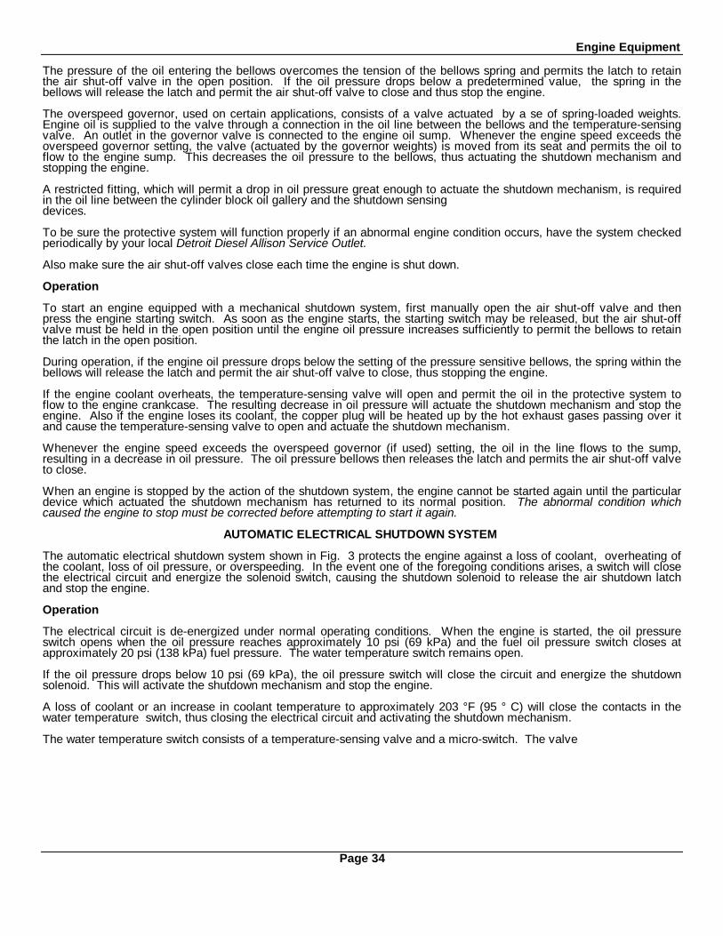
Engine Equipment
The pressure of the oil entering the bellows overcomes the tension of the bellows spring and permits the latch to retainthe air shut-off valve in the open position. If the oil pressure drops below a predetermined value, the spring in thebellows will release the latch and permit the air shut-off valve to close and thus stop the engine.
The overspeed governor, used on certain applications, consists of a valve actuated by a se of spring-loaded weights.Engine oil is supplied to the valve through a connection in the oil line between the bellows and the temperature-sensingvalve. An outlet in the governor valve is connected to the engine oil sump. Whenever the engine speed exceeds theoverspeed governor setting, the valve (actuated by the governor weights) is moved from its seat and permits the oil toflow to the engine sump. This decreases the oil pressure to the bellows, thus actuating the shutdown mechanism andstopping the engine.
A restricted fitting, which will permit a drop in oil pressure great enough to actuate the shutdown mechanism, is requiredin the oil line between the cylinder block oil gallery and the shutdown sensingdevices.
To be sure the protective system will function properly if an abnormal engine condition occurs, have the system checkedperiodically by your local Detroit Diesel Allison Service Outlet.
Also make sure the air shut-off valves close each time the engine is shut down.
Operation
To start an engine equipped with a mechanical shutdown system, first manually open the air shut-off valve and thenpress the engine starting switch. As soon as the engine starts, the starting switch may be released, but the air shut-offvalve must be held in the open position until the engine oil pressure increases sufficiently to permit the bellows to retainthe latch in the open position.
During operation, if the engine oil pressure drops below the setting of the pressure sensitive bellows, the spring within thebellows will release the latch and permit the air shut-off valve to close, thus stopping the engine.
If the engine coolant overheats, the temperature-sensing valve will open and permit the oil in the protective system toflow to the engine crankcase. The resulting decrease in oil pressure will actuate the shutdown mechanism and stop theengine. Also if the engine loses its coolant, the copper plug will be heated up by the hot exhaust gases passing over itand cause the temperature-sensing valve to open and actuate the shutdown mechanism.
Whenever the engine speed exceeds the overspeed governor (if used) setting, the oil in the line flows to the sump,resulting in a decrease in oil pressure. The oil pressure bellows then releases the latch and permits the air shut-off valveto close.
When an engine is stopped by the action of the shutdown system, the engine cannot be started again until the particulardevice which actuated the shutdown mechanism has returned to its normal position. The abnormal condition whichcaused the engine to stop must be corrected before attempting to start it again.
AUTOMATIC ELECTRICAL SHUTDOWN SYSTEM
The automatic electrical shutdown system shown in Fig. 3 protects the engine against a loss of coolant, overheating ofthe coolant, loss of oil pressure, or overspeeding. In the event one of the foregoing conditions arises, a switch will closethe electrical circuit and energize the solenoid switch, causing the shutdown solenoid to release the air shutdown latchand stop the engine.
Operation
The electrical circuit is de-energized under normal operating conditions. When the engine is started, the oil pressureswitch opens when the oil pressure reaches approximately 10 psi (69 kPa) and the fuel oil pressure switch closes atapproximately 20 psi (138 kPa) fuel pressure. The water temperature switch remains open.
If the oil pressure drops below 10 psi (69 kPa), the oil pressure switch will close the circuit and energize the shutdownsolenoid. This will activate the shutdown mechanism and stop the engine.
A loss of coolant or an increase in coolant temperature to approximately 203 °F (95 ° C) will close the contacts in thewater temperature switch, thus closing the electrical circuit and activating the shutdown mechanism.
The water temperature switch consists of a temperature-sensing valve and a micro-switch. The valve
Page 34
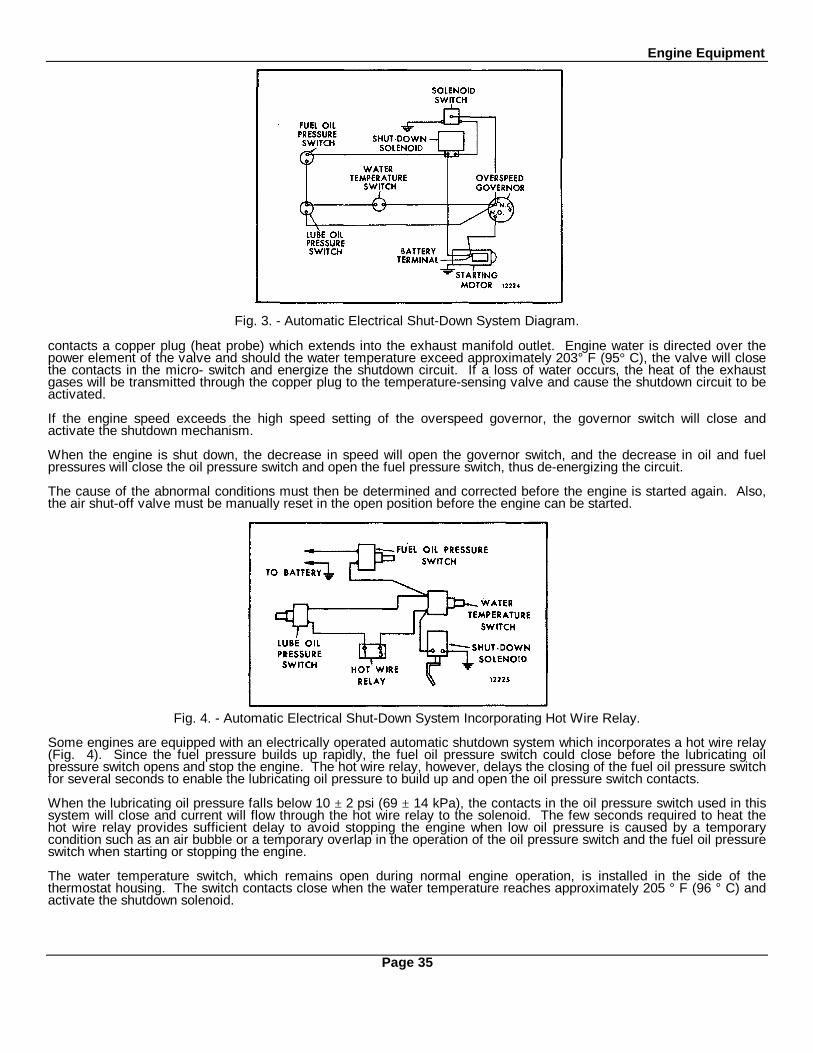
Engine Equipment
Fig. 3. - Automatic Electrical Shut-Down System Diagram.
contacts a copper plug (heat probe) which extends into the exhaust manifold outlet. Engine water is directed over thepower element of the valve and should the water temperature exceed approximately 203° F (95° C), the valve will closethe contacts in the micro- switch and energize the shutdown circuit. If a loss of water occurs, the heat of the exhaustgases will be transmitted through the copper plug to the temperature-sensing valve and cause the shutdown circuit to beactivated.
If the engine speed exceeds the high speed setting of the overspeed governor, the governor switch will close andactivate the shutdown mechanism.
When the engine is shut down, the decrease in speed will open the governor switch, and the decrease in oil and fuelpressures will close the oil pressure switch and open the fuel pressure switch, thus de-energizing the circuit.
The cause of the abnormal conditions must then be determined and corrected before the engine is started again. Also,the air shut-off valve must be manually reset in the open position before the engine can be started.
Fig. 4. - Automatic Electrical Shut-Down System Incorporating Hot Wire Relay.
Some engines are equipped with an electrically operated automatic shutdown system which incorporates a hot wire relay(Fig. 4). Since the fuel pressure builds up rapidly, the fuel oil pressure switch could close before the lubricating oilpressure switch opens and stop the engine. The hot wire relay, however, delays the closing of the fuel oil pressure switchfor several seconds to enable the lubricating oil pressure to build up and open the oil pressure switch contacts.
When the lubricating oil pressure falls below 10 ± 2 psi (69 ± 14 kPa), the contacts in the oil pressure switch used in thissystem will close and current will flow through the hot wire relay to the solenoid. The few seconds required to heat thehot wire relay provides sufficient delay to avoid stopping the engine when low oil pressure is caused by a temporarycondition such as an air bubble or a temporary overlap in the operation of the oil pressure switch and the fuel oil pressureswitch when starting or stopping the engine.
The water temperature switch, which remains open during normal engine operation, is installed in the side of thethermostat housing. The switch contacts close when the water temperature reaches approximately 205 ° F (96 ° C) andactivate the shutdown solenoid.
Page 35

Engine Equipment
ALARM SYSTEM
Fig. 5 - Alarm System Wiring Diagram.
The alarm system shown in Fig. 5 is similar to the automatic electrical shutdown system, but uses a warning bell in placeof the air shut-off valve solenoid. The bell warns the engine operator if the engine coolant overheats or the oil pressuredrops below the safe operating limit.
When the engine is started and the oil pressure is sufficient to open the oil pressure switch contacts (opening pressure isstamped on the switch cover), the alarm switch must be turned on manually to put the system in operation. The watertemperature switch is normally open. Should the engine coolant exceed 205° ± 5° F (96° ± -15° C), the watertemperature switch will close the electrical circuit and sound the alarm bell. Likewise, if the oil pressure drops below thesetting of the oil pressure switch, the switch will close and cause the bell to ring. The bell will continue to ring until theengine operator turns the alarm switch off. The alarm switch must also be turned off before a routine stop since thedecreasing oil pressure will close the oil pressure switch and cause the bell to ring.
If the alarm bell rings during engine operation, stop the engine immediately and determine the cause of the abnormalcondition. Make the necessary corrections before starting the engine again.
Page 36
Engine Equipment
STARTING SYSTEMS
ELECTRICAL STARTING SYSTEM
The electrical system on the engine generally consists of a battery-charging alternator, a starting motor, voltageregulator, storage battery, starter switch and the necessary wiring. Additional electrical equipment may be installed onthe engine unit at the option of the owner.
Starting Motor
The starting motor has a Sprag overrunning clutch. Pressing the starting switch engages the starting motor pinion withthe teeth of the flywheel ring gear and energizes the starting motor. The starting motor drives the pinion and rotates thecrankshaft. When the engine begins to operate, the Sprag clutch permits the pinion to overrun on its shaft, until thestarting switch is released, and prevents overspeeding the starting motor.
Starter Switch
To start the engine, a switch is used to energize the starting motor. Release the switch immediately after the enginestarts.
Alternator
The battery-charging alternator provides the electrical current required to maintain the storage battery in a chargedcondition and to supply sufficient current to carry any other electrical load requirements up to the rated capacity of thealternator.
Regulator
A voltage regulator is introduced into the electrical system to regulate the voltage and current output of the battery-charging alternator and to maintain a fully charged storage battery.
Storage Battery
The lead-acid storage battery is an electrochemical device for converting chemical energy into electrical energy.
The battery has three major functions:
1. It provides a source of electrical power for starting the engine.
2. It acts as a stabilizer to the voltage in the electrical system.
3. It can, for a limited time, furnish current when the electrical demands of the unit exceed the output of the alternator.
The battery is a perishable item which requires periodic servicing. A properly cared for battery will give long and trouble-free service.
1. Check the level of the electrolyte regularly. Add water if necessary, but do not overfill. Overfilling can cause poorperformance or early failure.
2. Keep the top of the battery clean. When necessary, wash with a baking soda solution and rinse with fresh water.Do not allow the soda solution to enter the cells.
3. Inspect the cables, clamps and hold-down bracket regularly. Clean and re-apply a light coating of grease whenneeded. Replace corroded, damaged parts.
4. Use the standard, quick in-the-unit battery test as the regular service test to check battery condition.
5. Check the electrical system if the battery becomes discharged repeatedly.
If the engine is to be stored for more than 30 days, remove the battery. The battery should be stored in a cool, dry place.Keep the battery fully charged and check the level of the electrolyte regularly. The Lubrication and PreventiveMaintenance section of this manual covers the servicing of the starting motor and alternator.
Consult an authorized Detroit Diesel Allison Service Outlet for information regarding the electrical system.
Page 37

Engine Equipment
HYDRAULIC STARTING SYSTEM (HYDROSTARTER)
The hydrostarter system schematically illustrated in Fig. 6 is a complete hydraulic system for starting internalcombustion engines. The system is automatically recharged after each start, and can be manually recharged. Thestarting potential remains during long periods of inactivity, and continuous exposure to hot or cold climates has nodetrimental effect upon the hydrostarter system. Also, the hydrostarter torque for a given pressure remains substantiallythe same regardless of the ambient temperature.
The hydrostarter system consists of a reservoir, an engine-driven charging pump, a hand pump, a piston typeaccumulator, a starting motor and connecting hoses and fittings.
Operation
Hydraulic fluid flows by gravity, or a slight vacuum, from the reservoir to either the engine-driven pump or the handpump inlet. Fluid discharging from either pump outlet at high pressure flows into the accumulator and is stored at 3250psi (22 383 kPa) under the pressure of compressed nitrogen gas. When the starter is engaged with the engine flywheelring gear and the control valve is opened, fluid under pressure is forced out of the accumulator, by the expandingnitrogen gas, and flows into the starting motor which rapidly accelerates the engine to a high. cranking speed. The usedfluid returns directly to the reservoir from the starter.
The engine-driven charging pump runs continuously during engine operation and automatically recharges theaccumulator. When the required pressure is attained in the accumulator, a valve within the pump body opens and thefluid discharged by the pump is by-passed to the reservoir. The system can be shut down and the pressure in theaccumulator will be maintained.
The precharge pressure of the accumulator is the pressure of the nitrogen gas with which the accumulator is initiallycharged. This pressure must be checked before the system pressure is raised for the initial engine start. To check theprecharge pressure, open the relief valve, on the side of the hand pump, approximately 1/2 turn, allowing the pressuregage to return to zero. Close the relief valve and pump several strokes on the hand pump. The gage should show arapid pressure rise from zero to the nitrogen precharge pressure, where it will remain without change for severaladditional strokes of the pump.
Fig. 6 - Schematic Diagram of Hydrostarter System Showing Oil Flow
Page 38
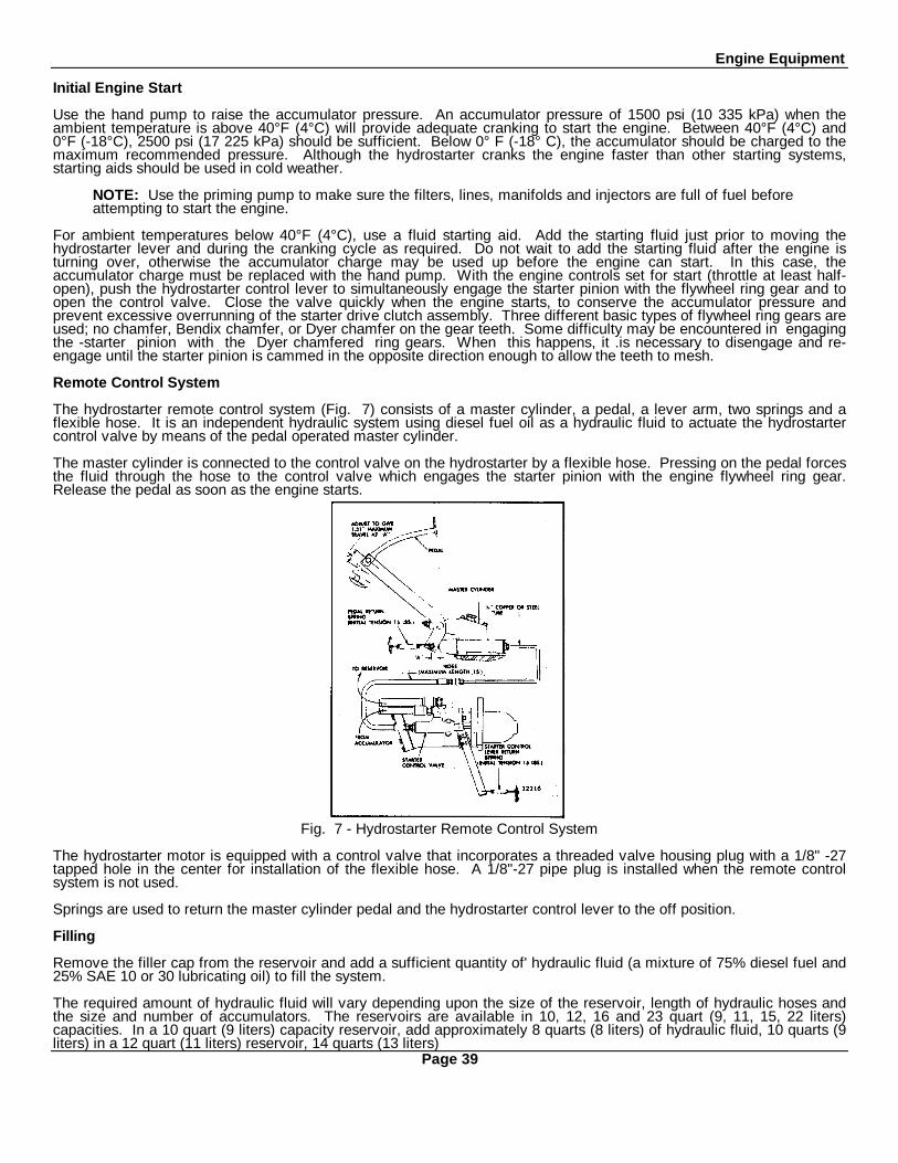
Engine Equipment
Initial Engine Start
Use the hand pump to raise the accumulator pressure. An accumulator pressure of 1500 psi (10 335 kPa) when theambient temperature is above 40°F (4°C) will provide adequate cranking to start the engine. Between 40°F (4°C) and0°F (-18°C), 2500 psi (17 225 kPa) should be sufficient. Below 0° F (-18° C), the accumulator should be charged to themaximum recommended pressure. Although the hydrostarter cranks the engine faster than other starting systems,starting aids should be used in cold weather.
NOTE: Use the priming pump to make sure the filters, lines, manifolds and injectors are full of fuel beforeattempting to start the engine.
For ambient temperatures below 40°F (4°C), use a fluid starting aid. Add the starting fluid just prior to moving thehydrostarter lever and during the cranking cycle as required. Do not wait to add the starting fluid after the engine isturning over, otherwise the accumulator charge may be used up before the engine can start. In this case, theaccumulator charge must be replaced with the hand pump. With the engine controls set for start (throttle at least half-open), push the hydrostarter control lever to simultaneously engage the starter pinion with the flywheel ring gear and toopen the control valve. Close the valve quickly when the engine starts, to conserve the accumulator pressure andprevent excessive overrunning of the starter drive clutch assembly. Three different basic types of flywheel ring gears areused; no chamfer, Bendix chamfer, or Dyer chamfer on the gear teeth. Some difficulty may be encountered in engagingthe -starter pinion with the Dyer chamfered ring gears. When this happens, it .is necessary to disengage and re-engage until the starter pinion is cammed in the opposite direction enough to allow the teeth to mesh.
Remote Control System
The hydrostarter remote control system (Fig. 7) consists of a master cylinder, a pedal, a lever arm, two springs and aflexible hose. It is an independent hydraulic system using diesel fuel oil as a hydraulic fluid to actuate the hydrostartercontrol valve by means of the pedal operated master cylinder.
The master cylinder is connected to the control valve on the hydrostarter by a flexible hose. Pressing on the pedal forcesthe fluid through the hose to the control valve which engages the starter pinion with the engine flywheel ring gear.Release the pedal as soon as the engine starts.
Fig. 7 - Hydrostarter Remote Control System
The hydrostarter motor is equipped with a control valve that incorporates a threaded valve housing plug with a 1/8" -27tapped hole in the center for installation of the flexible hose. A 1/8"-27 pipe plug is installed when the remote controlsystem is not used.
Springs are used to return the master cylinder pedal and the hydrostarter control lever to the off position.
Filling
Remove the filler cap from the reservoir and add a sufficient quantity of' hydraulic fluid (a mixture of 75% diesel fuel and25% SAE 10 or 30 lubricating oil) to fill the system.
The required amount of hydraulic fluid will vary depending upon the size of the reservoir, length of hydraulic hoses andthe size and number of accumulators. The reservoirs are available in 10, 12, 16 and 23 quart (9, 11, 15, 22 liters)capacities. In a 10 quart (9 liters) capacity reservoir, add approximately 8 quarts (8 liters) of hydraulic fluid, 10 quarts (9liters) in a 12 quart (11 liters) reservoir, 14 quarts (13 liters)
Page 39
Engine Equipment
in a 16 quart (15 liters) reservoir or 21 quarts (20 liters) in a 23 quart (22 liters) reservoir.
NOTE: When the accumulator is charged to 3000 psi (20 670 kPa) and all hoses are filled, there shouldbe enough hydraulic fluid remaining in the reservoir to completely cover the screen in the bottom of thereservoir.
Purging
A by-pass valve is located on the inlet side of the hand pump. Loosen the lock nut and rotate this valve approximatelyone turn counterclockwise with a screw driver. Operate the hand pump for 12 to 15 complete strokes. Do not pump toorapidly. Close the by-pass valve tightly and tighten the lock nut.
1. Move the starter control lever to engage the pinion with the flywheel and open the control valve. While holding thelever in this position, operate the hand pump until the starter has turned several revolutions. Close the control valve.Loosen the swivel hose fitting at the discharge side of the engine-driven pump about two turns. Operate the hand pumpto force air out until oil begins to appear at the loose fitting. Tighten the swivel hose fitting and pressurize the systemwith the hand pump sufficiently to start the engine.
2. Perform the initial starting instructions under Preparation for Starting Engine First Time. Then, with the enginerunning at least 1500 rpm, purge the engine-driven pump of air. Break the hose connection at the discharge side of theengine driven-pump until a full stream of oil is discharged from the pump. Connect the hose to the pump and alternatelyloosen and tighten the swivel fitting on the discharge hose until the oil leaking out, when the fitting is loose, appears tobe free of air bubbles. Tighten the fitting securely and observe the pressure gage. The pressure should rise rapidly tothe accumulator precharge pressure (1250 psi or 10 413 kPa at 70°F or 21°C), then increase slowly, reaching 2900 to3300 psi (19 981 to 22 737 kPa).
3. After the pressure has stabilized near 3000 psi (20 670 kPa), examine all of the high pressure hoses, connectionsand fittings for leaks.
4. The engine-driven pump must by-pass oil to the reservoir when the accumulator pressure reaches 2900 to 3300 psi(19 981 to 22-737 kPa). To determine whether the pump by-pass valve is operating properly, remove the reservoir fillercap, disconnect the pump by-pass hose at the reservoir, and hold the hose over the open reservoir filler spout. Anoccasional spurt of oil may be emitted from the hose prior to by-passing. When the by-pass valve opens, a full andcontinuous stream of oil will flow from the hose. Reconnect the hose to the reservoir and install the filler cap.
5. Fill the reservoir to the proper level.
The hydrostarter remote control system may be purged of air as follows:
1. Fill the master cylinder with fuel oil.
2. Loosen the hose fitting at the hydrostarter control valve.
3. Actuate the master cylinder pedal until all of the air is discharged from the system and a solid stream of fuel oil isbeing discharged with each stroke.
NOTE: Replenish the fluid in the master cylinder as required during the purging operation.
4. Tighten the hose fitting and check for leaks.
LUBRICATION AND PREVENTIVEMAINTENANCE
Inspect the system periodically for leaks. Primarily, examine the high pressure hoses, connections, fittings and thecontrol valve on the starter. Make certain that the oil level in the reservoir is sufficient to completely cover the screen atthe bottom of the tank. Make this check after the accumulator is charged and the engine driven pump is by-passing oil tothe reservoir. Every 2000 hours, or as conditions warrant, drain the reservoir and remove the screen. Flush out thereservoir and clean the screen and filler cap. Then reinstall the screen. Remove the bowl and element from the filter inthe engine-driven pump supply hose. Wash the bowl and element in clean fuel oil and reassemble the filter. Releasethe pressure and drain the remaining hydraulic fluid from the system by disconnecting the hoses from the hydrostartercomponents. Then reconnect all of the hydraulic hoses.
WARNING: The oil pressure in the system must be released prior to servicing the hydrostarter motor orother components to prevent possible injury to personnel or equipment.
NOTE: Make sure all hoses and fittings are clean before any connections are made.
Fill the hydrostarter system with new clean fluid.
Page 40
ENGINE EQUIPMENT
Lubrication
Remove the hydrostarter from the engine every 2000 hours for lubrication, Before removing the hydrostarter, release thepressure in the system by means of the relief valve in the hand pump. Then remove the three bolts which retain thestarting motor to the flywheel housing. Remove the starting motor without disconnecting the hydraulic oil hoses. Thiswill prevent dirt and air from entering the hydraulic system.
Apply a good quality, lightweight grease on the drive clutch pinion to make sure the clutch will slide freely whilecompressing the spring. Also apply grease to, the fingers of the clutch fork and on the spool of the clutch yoke engagedby the fork. This lubrication period may be reduced or lengthened according to the severity of service.
Remove the pipe plug from the starting motor drive housing and saturate the shaft oil wick with engine oil. Then reinstallthe plug.
After lubricating, install the starting motor on the flywheel housing and recharge the accumulator with the hand pump.
On engines equipped with a hydraulic remote control system, lubricate the shaft in the master cylinder through thepressure grease fitting every 2000 hours.
Cold Weather Operation
Occasionally, when an engine is operated in regions of very low temperatures, the starter drive clutch assembly may slipwhen the starter is engaged. If the clutch slips, proceed as follows:
1. Release the oil pressure in the system by opening the relief valve in the hand pump.
WARNING: The oil pressure in the system must be released prior to servicing the hydrostarter motor orother components to prevent possible injury to personnel or equipment.
2. Disconnect the hydraulic hoses from the starting motor.
3. Remove the three retaining bolts and lock washers and withdraw the starting motor from the flywheel housing.
4. Disassemble the starting motor.
5. Wash the hydrostarter drive clutch' assembly in clean fuel oil to remove the old lubricant.
6. When the clutch is free, apply SAE 5W lubricating oil.
7. Reassemble the starting motor and reinstall it on the engine. Then attach a tag to the starter noting the lubricantused in the clutch.
8. Recharge the accumulator with the hand pump.
Marine Application
In addition to the normal hydrostarter lubrication and maintenance instructions, the following special precautions must betaken for marine installations or other cases where equipment is subject to salt spray and air, or other corrosiveatmospheres:
1. Clean all exposed surfaces and apply a coat of zinc-chromate primer, followed by a coat of suitable paint.
2. Apply a liberal coating of Lubriplate, type 130-AA, or equivalent, to the following surfaces.
a. The exposed end of the starter control valve and around the control shaft where it passes through the clutchhousing.
b. The exposed ends of the hand pump cam pin.
3. Operate all of the moving parts and check the protective paint and lubrication every week.
Consult an authorized Detroit Diesel Allison Service Outlet for any information relating to the hydrostarter system.
COLD WEATHER STARTING AIDS
In a diesel engine, the fuel injected into the combustion chamber is ignited by the heat, of the air compressed into thecylinder; However, when starting an engine in extremely cold weather, a large part of the energy of combustion isabsorbed by the pistons and cylinder walls, and in overcoming the high friction created by the cold lubricating oil.
Page 41
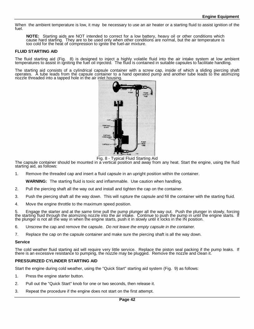
Engine Equipment
When the ambient temperature is low, it may be necessary to use an air heater or a starting fluid to assist ignition of thefuel.
NOTE: Starting aids are NOT intended to correct for a low battery, heavy oil or other conditions whichcause hard starting. They are to be used only when other conditions are normal, but the air temperature istoo cold for the heat of compression to ignite the fuel-air mixture.
FLUID STARTING AID
The fluid starting aid (Fig. 8) is designed to inject a highly volatile fluid into the air intake system at low ambienttemperatures to assist in igniting the fuel oil injected. The fluid is contained in suitable capsules to facilitate handling.
The starting aid consists of a cylindrical capsule container with a screw cap, inside of which a sliding piercing shaftoperates. A tube leads from the capsule container to a hand operated pump and another tube leads to the atomizingnozzle threaded into a tapped hole in the air inlet housing.
Fig. 8 - Typical Fluid Starting AidThe capsule container should be mounted in a vertical position and away from any heat. Start the engine, using the fluidstarting aid, as follows:
1. Remove the threaded cap and insert a fluid capsule in an upright position within the container.
WARNING: The starting fluid is toxic and inflammable. Use caution when handling.
2. Pull the piercing shaft all the way out and install and tighten the cap on the container.
3. Push the piercing shaft all the way down. This will rupture the capsule and fill the container with the starting fluid.
4. Move the engine throttle to the maximum speed position.
5. Engage the starter and at the same time pull the pump plunger all the way out. Push the plunger in slowly, forcingthe starting fluid through the atomizing nozzle into the air intake. Continue to push the pump in until the engine starts. Ifthe plunger is not all the way in when the engine starts, push it in slowly until it locks in the IN position.
6. Unscrew the cap and remove the capsule. Do not leave the empty capsule in the container.
7. Replace the cap on the capsule container and make sure the piercing shaft is all the way down.
Service
The cold weather fluid starting aid will require very little service. Replace the piston seal packing if the pump leaks. Ifthere is an excessive resistance to pumping, the nozzle may be plugged. Remove the nozzle and clean it.
PRESSURIZED CYLINDER STARTING AID
Start the engine during cold weather, using the "Quick Start" starting aid system (Fig. 9) as follows:
1. Press the engine starter button.
2. Pull out the "Quick Start" knob for one or two seconds, then release it.
3. Repeat the procedure if the engine does not start on the first attempt.
Page 42
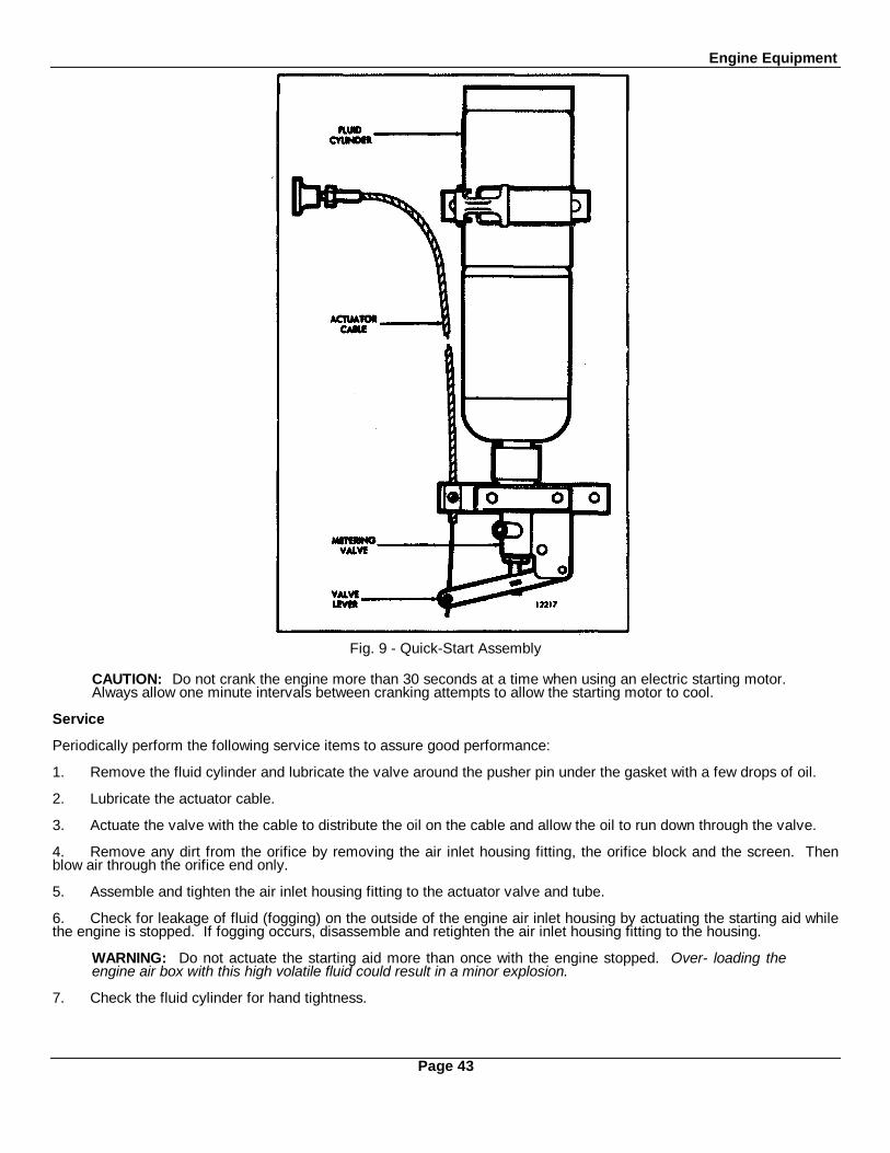
Engine Equipment
Fig. 9 - Quick-Start Assembly
CAUTION: Do not crank the engine more than 30 seconds at a time when using an electric starting motor.Always allow one minute intervals between cranking attempts to allow the starting motor to cool.
Service
Periodically perform the following service items to assure good performance:
1. Remove the fluid cylinder and lubricate the valve around the pusher pin under the gasket with a few drops of oil.
2. Lubricate the actuator cable.
3. Actuate the valve with the cable to distribute the oil on the cable and allow the oil to run down through the valve.
4. Remove any dirt from the orifice by removing the air inlet housing fitting, the orifice block and the screen. Thenblow air through the orifice end only.
5. Assemble and tighten the air inlet housing fitting to the actuator valve and tube.
6. Check for leakage of fluid (fogging) on the outside of the engine air inlet housing by actuating the starting aid whilethe engine is stopped. If fogging occurs, disassemble and retighten the air inlet housing fitting to the housing.
WARNING: Do not actuate the starting aid more than once with the engine stopped. Over- loading theengine air box with this high volatile fluid could result in a minor explosion.
7. Check the fluid cylinder for hand tightness.
Page 43
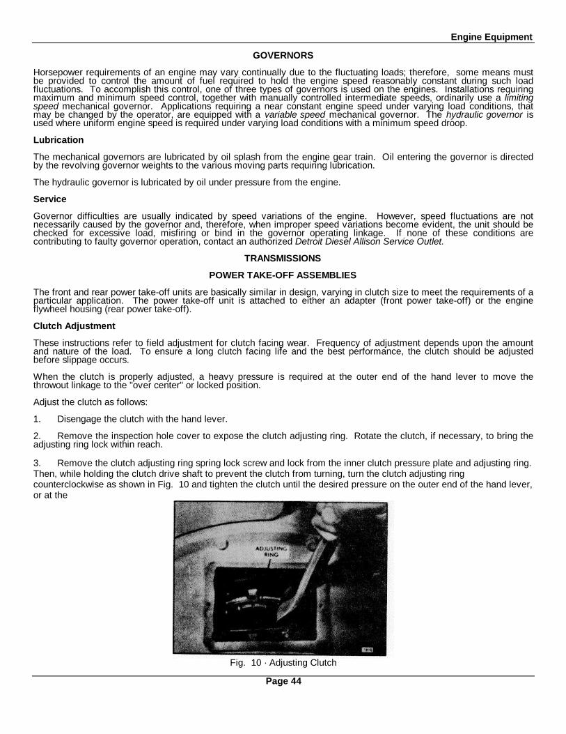
Engine Equipment
GOVERNORS
Horsepower requirements of an engine may vary continually due to the fluctuating loads; therefore, some means mustbe provided to control the amount of fuel required to hold the engine speed reasonably constant during such loadfluctuations. To accomplish this control, one of three types of governors is used on the engines. Installations requiringmaximum and minimum speed control, together with manually controlled intermediate speeds, ordinarily use a limitingspeed mechanical governor. Applications requiring a near constant engine speed under varying load conditions, thatmay be changed by the operator, are equipped with a variable speed mechanical governor. The hydraulic governor isused where uniform engine speed is required under varying load conditions with a minimum speed droop.
Lubrication
The mechanical governors are lubricated by oil splash from the engine gear train. Oil entering the governor is directedby the revolving governor weights to the various moving parts requiring lubrication.
The hydraulic governor is lubricated by oil under pressure from the engine.
Service
Governor difficulties are usually indicated by speed variations of the engine. However, speed fluctuations are notnecessarily caused by the governor and, therefore, when improper speed variations become evident, the unit should bechecked for excessive load, misfiring or bind in the governor operating linkage. If none of these conditions arecontributing to faulty governor operation, contact an authorized Detroit Diesel Allison Service Outlet.
TRANSMISSIONS
POWER TAKE-OFF ASSEMBLIES
The front and rear power take-off units are basically similar in design, varying in clutch size to meet the requirements of aparticular application. The power take-off unit is attached to either an adapter (front power take-off) or the engineflywheel housing (rear power take-off).
Clutch Adjustment
These instructions refer to field adjustment for clutch facing wear. Frequency of adjustment depends upon the amountand nature of the load. To ensure a long clutch facing life and the best performance, the clutch should be adjustedbefore slippage occurs.
When the clutch is properly adjusted, a heavy pressure is required at the outer end of the hand lever to move thethrowout linkage to the "over center" or locked position.
Adjust the clutch as follows:
1. Disengage the clutch with the hand lever.
2. Remove the inspection hole cover to expose the clutch adjusting ring. Rotate the clutch, if necessary, to bring theadjusting ring lock within reach.
3. Remove the clutch adjusting ring spring lock screw and lock from the inner clutch pressure plate and adjusting ring.Then, while holding the clutch drive shaft to prevent the clutch from turning, turn the clutch adjusting ringcounterclockwise as shown in Fig. 10 and tighten the clutch until the desired pressure on the outer end of the hand lever,or at the
Fig. 10 · Adjusting Clutch
Page 44

Engine Equipment
ClutchDiameter
Hand LeverLength
PressurePSI kPa
TorqueIb-ft Nm
8"10"
*11 1/2"11 1/2"
15 1/2"15 1/2"15 3/8"
20"
55 37980 552100 689105 724
56-63 76-8587-94 113-127129 175112-120 152-163
*Twin Disc ClutchTABLE 1
clutch release shaft (Fig. 11), is obtained as shown in Table 1.
When properly adjusted, the approximate pressure required at the outer end of the hand lever to engage the variousdiameter clutches is shown in the table. These specifications apply only with the hand lever which is furnished with thepower take-off.
A suitable spring scale may be used to check the pounds pressure required to engage the clutch. However, a moreaccurate method of checking the clutch adjustment is with a torque wrench as shown in Fig. 11.
To fabricate an adapter, saw the serrated end off of a clutch hand lever and weld a 1-1/8" nut (across the hex) on it asshown in Fig. 11. Then saw a slot through the nut.
When checking the clutch adjustment with a torque wrench, engage the clutch slowly and note the amount of torqueimmediately before the clutch engages (goes over center). The specified torque is shown in Table 1.
CAUTION: The thrust load on the bronze clutch release bearing should be kept at an absolute minimum.Therefore, the hand lever should be positioned on the shaft as near the 12 o'clock or 6 o'clock position aspossible. The 9 and 3 o'clock positions are to be avoided.
Fig. 11 - Checking Clutch Adjustment with a Torque Wrench and Adapter
Make a final clutch adjustment with the engine running as follows:
1. Start the engine and operate it at idling speed (approximately 500 rpm) with the clutch disengaged. The speed willbe sufficient to move the segments out to the operating position.
2. Check the pressure required to engage the clutch. The engagement pressure should be the same as that followingthe adjustment. If the clutch engages at a lower pressure, the adjustment was probably made against the unworn portionof the facing.
3. Stop the engine and readjust the clutch, making sure all disc segments are properly positioned. Install theinspection hole cover.
TORQMATIC CONVERTERS
The Torqmatic converter is a self contained unit which transfers and multiplies the torque of the prime mover. This unittransmits the power through the action of oil instead of through gears and in addition to multiplying the torque also actsas a fluid coupling between the engine and the equipment to be powered. The converter will automatically adjust theoutput torque to load requirements.
There are various combinations of Torqmatic converters with features such as: an automotive or industrial flange on theshaft, a hydraulically operated lock-up clutch, a manual input disconnect clutch, and an accessory drive for either agovernor or tachometer.
Check the oil level daily. If the converter is equipped with an input disconnect clutch, additional checks andservice will be necessary daily or at intervals determined by the type of operation.Adjust the disconnect clutches as outlined under power take-off clutch adjustment.
Contact an authorized Detroit Diesel Allison Service Outlet for service on Torqmatic converters.Page 45

Engine Equipment
The Warner hydraulic marine gear assembly consists of a hydraulically operated multiple disc clutch in combination witha hydraulically actuated reversing gear train, an oil pressure regulator, an oil sump independent of the engine oil systemand an oil cooler mounted on the engine.
Oil pressure for the operation of the marine gear is provided by an oil pump incorporated within the gear housing anddriven continuously while the engine is running. The oil is delivered under pressure from the pump to a combinationmarine gear control valve and pressure regulator valve.
The pressure regulator valve maintains constant pressure over a wide speed range and the control valve directs the oilunder pressure to either the forward or reverse piston cylinder. The operating oil pressure range for the marine gear atoperating speed is 120 to 140 psi (827 to 965 kPa) and the maximum oil temperature is 225°F (107°C). Minimum oilpressure is 100 psi (689 kPa) at idle speed (600 rpm).
Shifting from forward to reverse drive through neutral may be made at any speed; however, it is advisable to shift at lowspeeds, below 1000 engine rpm, to avoid damage to the engine, reverse gear or shaft. The marine reverse and reductiongear is lubricated by pressure and splash. The quantity of oil in the marine gear will vary with the inclination of theengine and must be properly maintained to the full mark on the dipstick to ensure satisfactory operation.
It is recommended that vessels utilizing a marine gear have-a suitable locking device or brake to prevent rotation of thepropeller shaft when the vessel is not under direct propulsion. If the marine gear is not in operation and the forwardmotion of the vessel causes the propeller shaft to rotate, lubricating oil will not be circulated through the gear because theoil pump is not in operation. Overheating and damage to the marine gear may result unless rotation of the propellershaft is prevented.
Consult an authorized Detroit Diesel Allison Service Outlet for major repairs or reconditioning of the marine gear.
Page 46

OPERATING INSTRUCTIONS
ENGINE OPERATING INSTRUCTIONS
PREPARATION FOR STARTING ENGINE FIRST TIME
Before starting an engine for the first time, carefully read and follow these instructions. Attempting to run the enginebefore studying these instructions may result in serious damage to the engine.
NOTE: When preparing to start a new or overhauled engine or an engine which has been in storage,perform all of the operations listed below. Before a routine start (at each shift), see Daily Operations in theLubrication and Preventive Maintenance Chart.
Cooling System
Install all of the drain cocks or plugs in the cooling system (drain cocks are removed for shipping). Open the coolingsystem vents, if the engine is so equipped.
Remove the filler cap and fill the cooling system with clean, soft water or a protective solution consisting of high boilingpoint type antifreeze, if the engine will be exposed to freezing temperatures. Refer to Engine Coolant. Keep the liquidlevel about two inches below the filler neck to allow for fluid expansion.
Use a quality rust inhibitor if only water is used in the cooling system.
Close the vents, if used, after filling the cooling system.
On marine installations, prime the raw water cooling system and open any sea cocks in the raw water pump intake line.Prime the raw water pump by removing the pipe plug or electrode provided in the pump outlet elbow and pour water inthe pump.
CAUTION: Failure to prime the raw water pump may result in damage to the pump impeller.
Lubrication System
The lubricating oil film on the rotating parts and bearings of a new or overhauled engine, or one which has been instorage, may be insufficient for proper lubrication when the engine is started for the first time.
It is recommended that the engine lubricating system be charged with a pressure prelubricator, set to supply a minimumof 25 psi (172 kPa) oil pressure, to ensure an immediate flow of oil to all bearings at the initial engine start-up. The oilsupply line should be attached to the engine so that oil under pressure is supplied to the main oil gallery.
With the oil pan dry, use the prelubricator to prime the engine with sufficient oil to reach all bearing surfaces. Use heavy-duty lubricating oil as specified under Lubricating Oil Specifications. Then remove the dipstick, wipe it with a clean cloth,insert and remove it again to check the oil level in the oil pan. Add sufficient oil, if necessary, to bring it to the full markon the dipstick. Do not overfill.
If a pressure prelubricator is not available, fill the crankcase to the proper level with heavy-duty lubricating oil asspecified. Then pre-lubricate the upper engine parts by removing the valve rocker covers and pouring lubricating oil, ofthe same grade and viscosity as used in the crankcase, over the rocker arms.
Turbocharger
Disconnect the turbocharger oil inlet line and pour approximately one pint of clean engine oil in the line, thus makingsure the bearings are lubricated for the initial start. Reconnect the oil line.
Air Cleaner
If the engine is equipped with oil bath air cleaners, fill the air cleaner oil cups to the proper level with clean engine oil. Donot overfill.
Transmission
Fill the transmission case, marine gear or torque converter supply tank to the proper level with the lubricant specifiedunder Lubrication and Preventive Maintenance.
Fuel System
Fill the fuel tank with the fuel specified under Diesel Fuel Oil Specifications.
Page 47
Operating Instructions
If the unit is equipped with a fuel valve, it must be opened.
To ensure prompt starting, fill the fuel system between the pump and the fuel return manifold with fuel. If the engine hasbeen out of service for a considerable length of time, prime the filter between the fuel pump and the injectors. The filtermay be primed by removing the plug in the top of the filter cover and slowly filling the filter with fuel.
In addition to the above, on an engine equipped with a hydrostarter, use a priming pump to make sure the fuel lines andthe injectors are full of fuel before attempting to start the engine.
NOTE: The fuel system is filled with fuel before leaving the factory. If the fuel is still in the system whenpreparing to start the engine, priming should be unnecessary.
Lubrication Fittings
Fill all grease cups and lubricate at all fittings with an all purpose grease. Apply lubricating oil to the throttle linkage andother moving parts and fill the hinged cap oilers with a hand oiler.
Drive Belts
Adjust all drive belts as recommended under Lubrication and Preventive Maintenance.
Storage Battery
Check the battery. The top should be clean and dry, the terminals tight and protected with a coat of petroleum jelly andthe electrolyte must be at the proper level.
NOTE: When necessary, check the battery with a hydrometer; the reading should be 1.265 or higher.However, hydrometer readings should always be corrected for the temperature of the electrolyte.
Generator Set
Where applicable, fill the generator end bearing housing with the same lubricating oil as used in the engine.
A generator set should be connected and grounded in accordance with the applicable local electrical codes.
CAUTION: The base of a generator set must be grounded.
Clutch
Disengage the clutch, if the unit is so equipped.
STARTING
Before starting the engine for the first time, perform the operations listed under Preparation For Starting Engine FirstTime.
Before a routine start, see Daily Operations in the Lubrication and Preventive Maintenance Chart.
If a manual or an automatic shutdown system is incorporated in the unit, the control must be set in the open positionbefore starting the engine.
The blower will be seriously damaged if operated with the air shut-off valve in the closed position.
Starting at air temperatures below 40°F (4°C) requires the use of a cold weather starting aid. See Cold Weather Starting.
The instructions for the use of a cold weather fluid starting aid will vary dependent on the type being used. Referenceshould be made to these instructions before attempting a cold weather start.
WARNING: Starting fluid used in capsules is highly inflammable, toxic and possesses anesthetic properties.
Initial Engine Start (Electric)
Start an engine equipped with' an electric starting motor as follows: Set the speed control lever at part throttle, then bringit back to the desired no-load speed. In addition, on mechanical governors, make sure the stop lever on the governorcover is in the run position. Then press the starting motor switch firmly. If the engine fails to start within 30 seconds,release the starting switch and allow the starting motor to cool a few minutes before trying again. If the engine fails tostart after four attempts, an inspection should be made to determine the cause.
CAUTION: To prevent serious damage to the starter, if the engine does not start, do not press the startingswitch again while the starting motor is running.
Initial Engine Start (Hydrostarter)
Page 48

Operating Instructions
Ambient TemperaturePressure Gage
Reading
psi kPaAbove 40° F (4.4° C)40 - 0° F (4.4 to -18° C)Below 0° F (-18° C)
1500 10 3422500 17 2373300 22 753
Table 1
An engine equipped with a hydrostarter may be started as follows:
Raise the hydrostarter accumulator pressure with the hand pump until the gage reads as indicated in Table 1.
Set the engine controls for starting with the throttle at least half open.
NOTE: During cold weather add starting fluid at the same time the hydrostarter motor lever is moved. Donot wait to add the fluid after the engine is turning over.
Push the hydrostarter control lever to simultaneously engage the starter pinion with the flywheel ring gear and to open thecontrol valve . Close the valve as soon as the engine starts to conserve the accumulator pressure and to avoidexcessive over-running of the starter drive clutch assembly.
RUNNING
Oil Pressure
Observe the oil pressure gage immediately after starting the engine. If there is no pressure indicated within 10 to 15seconds, stop the engine and check the lubricating oil system. The minimum oil pressure should be at least 18 psi (124kPa) at 1200 rpm. The oil pressure at normal operating speed should be 40-60 psi (276-414 kPa).
Warm- Up
Run the engine at part throttle and no-load for approximately five minutes, allowing it to warm-up before applying a load.
If the unit is operating in a closed room, start the room ventilating fan or open the windows, as weather conditions permit,so ample air is available for the engine.
Clutch
Do not engage the clutch at engine speeds over 1000 rpm.
Inspection
While the engine is running at operating temperature, check for coolant, fuel or lubricating oil leaks. Tighten the lineconnections where necessary to stop leaks.
Engine Temperature
Normal engine coolant temperature is 160-185° F (71- 85° C).
Crankcase
If the engine crankcase was refilled, stop the engine after normal operating temperature has been reached, allow the oilto drain back into the crankcase for approximately twenty minutes and check the oil level. Add oil, if necessary, to bringit to the proper level on the dipstick.
Use only the heavy duty lubricating oil specified under Lubricating Oil Specifications.
Cooling System
Remove the radiator or heat exchanger tank cap slowly after the engine has reached normal operating temperature andcheck the engine coolant level. The coolant level should be near the top of the opening. If necessary, add 'clean softwater or a high boiling point type antifreeze (refer to Engine Coolant).
Marine Gear
Check the marine gear oil pressure. The operating oil pressure range for the marine gear at operating speed is 120 to160 psi (827 to 1103 kPa) and minimum oil pressure is 100 psi (689 kPa) at idle speed (600 rpm).
Turbocharger
Make a visual inspection of the turbocharger for leaks and excessive vibration. Stop the engine immediately if there isan unusual noise in the turbocharger.
Page 49
Operating Instructions
Avoid Unnecessary Engine Idling
During long engine idling periods, the engine coolant temperature will fall below the normal operating range. Theincomplete combustion of fuel in a cold engine will cause crankcase dilution, formation of lacquer or gummy deposits onthe valves, pistons and rings and rapid accumulation of sludge in the engine.
NOTE: When prolonged engine idling is necessary, maintain at least 800 rpm.
STOPPING
Normal Stopping
1. Release the load and decrease the engine speed. Put all shift levers in the neutral position.
2. Allow the engine to run at half speed or slower with no load for four or five minutes, then move the stop lever tostop to shut down the engine.
Emergency Stopping
If the engine does not stop after using the normal stopping procedure, pull the "Emergency Stop" knob all the way out.This control cuts off the air to the engine. Do not try to restart again until the cause for the malfunction has been foundand corrected.
CAUTION: The emergency shutdown system should never be used except in an emergency. Use of theemergency shutdown can cause oil to be sucked past the oil seals and into the blower housing.
The air shut-off valve, located on the blower air inlet housing, must be reset by hand and the "Emergency Stop" knobpushed in before the engine is ready to start again.
Fuel System
If the unit is equipped with a fuel valve, close it. Fill the fuel tank; a full tank minimizes condensation.
Exhaust System
Drain the condensation from the exhaust line or silencer.
Cooling System
Drain the cooling system if it is not protected with antifreeze and freezing temperatures are expected. Leave the drainsopen. Open the raw water drains of a heat exchanger cooling system.
Crankcase
If the engine crankcase was refilled, stop the engine after normal operating temperature has been reached, allow the oilto drain (approximately 20 minutes) back into the crankcase and check the oil level. Add oil, if necessary, to bring it tothe proper level on the dipstick.
Use only the heavy-duty lubricating oil specified under Lubricating Oil Specifications.
Transmission
Check and, if necessary, replenish the oil supply in the transmission.
Clean Engine
Clean and check the engine thoroughly to make certain it will be ready for the next run.
Refer to Lubrication and Preventive Maintenance and perform all of the daily maintenance operations. Also perform theoperations required for the number of hours or miles the engine has been in operation.
Make the necessary adjustments and minor repairs to correct difficulties which became apparent to the operator duringthe last run.
Page 50
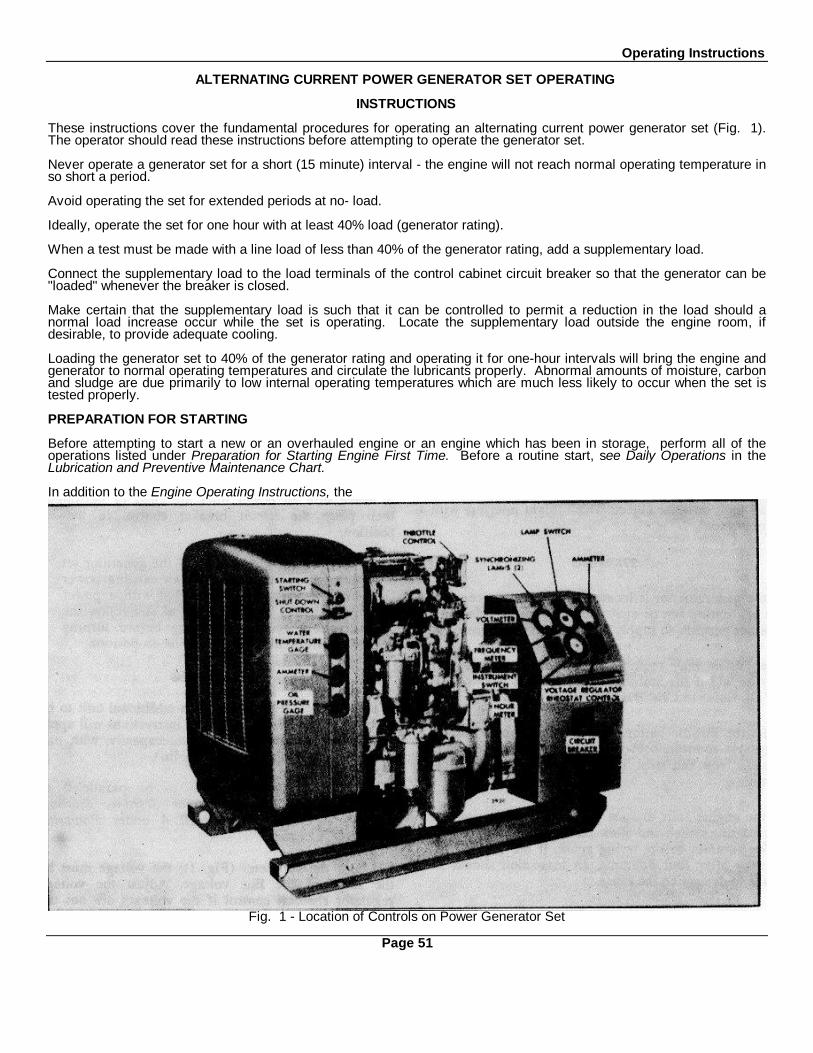
Operating Instructions
ALTERNATING CURRENT POWER GENERATOR SET OPERATING
INSTRUCTIONS
These instructions cover the fundamental procedures for operating an alternating current power generator set (Fig. 1).The operator should read these instructions before attempting to operate the generator set.
Never operate a generator set for a short (15 minute) interval - the engine will not reach normal operating temperature inso short a period.
Avoid operating the set for extended periods at no- load.
Ideally, operate the set for one hour with at least 40% load (generator rating).
When a test must be made with a line load of less than 40% of the generator rating, add a supplementary load.
Connect the supplementary load to the load terminals of the control cabinet circuit breaker so that the generator can be"loaded" whenever the breaker is closed.
Make certain that the supplementary load is such that it can be controlled to permit a reduction in the load should anormal load increase occur while the set is operating. Locate the supplementary load outside the engine room, ifdesirable, to provide adequate cooling.
Loading the generator set to 40% of the generator rating and operating it for one-hour intervals will bring the engine andgenerator to normal operating temperatures and circulate the lubricants properly. Abnormal amounts of moisture, carbonand sludge are due primarily to low internal operating temperatures which are much less likely to occur when the set istested properly.
PREPARATION FOR STARTING
Before attempting to start a new or an overhauled engine or an engine which has been in storage, perform all of theoperations listed under Preparation for Starting Engine First Time. Before a routine start, see Daily Operations in theLubrication and Preventive Maintenance Chart.
In addition to the Engine Operating Instructions, the
Fig. 1 - Location of Controls on Power Generator Set
Page 51

Operating Instructions
following instructions also apply when operating an alternating current power generator set.
1. Before the first start, check the generator main bearing oil reservoir. If necessary, add sufficient lubricating oil, ofthe same grade as used in the engine crankcase, to bring it to the proper level on the sight gage.
2. Check the interior of the generator for dust or moisture. Blow out dust with low pressure air (25 psi or 172 kPamaximum). If there is moisture on the interior of the generator, it must be dried before the set is started. Refer to theappropriate Delco Products Maintenance bulletin.
3. The air shut-off valve located in the air inlet housing must be in the open or reset position.
4. Refer to Fig. 1 and place the circuit breaker in the off position.
5. If the generator set is equipped with synchronizing lamps, place the lamp switch in the off position.
6. Turn the voltage regulator rheostat knob counter- clockwise to its lower limit.
7. Make sure the power generator set has been cleared of all tools or other objects which might interfere with itsoperation.
STARTING
If the generator set is located in a closed space, start the ventilating fan or open the doors and windows, as weatherpermits, to supply ample air to the engine.
The engine may require the use of a cold weather starting aid if the ambient temperature is below 40° F (4° C). Refer toCold Weather Starting Aids.
Press the throttle button and turn the throttle control (Fig. 1) counterclockwise to a position midway between run andstop. Then press the starting switch firmly.
If the engine fails to start within 30 seconds, release the starting switch and allow the starting motor to cool a few minutesbefore trying again. If the engine fails to start after four attempts, an inspection should be made to determine the cause.
CAUTION: To prevent serious damage to the starter, if the engine does not start, do not press the startingswitch again while the starting motor is rotating.
RUNNING
Observe the engine oil pressure gage immediately after starting the engine. If there is no oil pressure indicated within 10to 15 seconds, stop the engine and check the engine lubricating system.
If the oil pressure is observed to be normal, increase the throttle setting to cause the engine to run at its synchronousspeed.
PREPARING GENERATOR FOR LOAD
After the engine is warmed up (or the oil pressure has stabilized) prepare the generator set for load as follows:
1. Bring the engine up to the rated speed.
2. Turn the instrument switch to the desired position.
3. Turn the voltage regulator rheostat knob slowly in a clockwise direction to raise the voltage, while watching thevoltmeter, until the desired voltage is attained.
4. If the generator set is equipped with a frequency meter, adjust the engine speed with the vernier throttle knob untilthe desired frequency is indicated on the meter.
5. Make sure all power lines are clear of personnel, then place the circuit breaker control in the on position.
NOTE: Perform Step 5 only if the generator set is not being paralleled with an existing power source. If itis being paralleled with a power source already on the line, read and follow the instructions underParalleling before turning the circuit breaker control to the on position.
PARALLELING
If the load conditions require an additional unit to be placed on the line, the following instructions will apply to powergenerator sets of equal capacity, with one generator set in operation on the line.
1. Prepare the generator set to be paralleled as outlined under Preparation For Starting, Starting, Running and Items1through 4 under Preparing Generator for Load.
2. Check the voltmeter (Fig. 1); the voltage must be the same as the line voltage. Adjust the voltage regulatorrheostat control if the voltages are not the same.
3. Place the synchronizing lamp switch, of the generator set to be paralleled, in the on position.
Page 52
Operating Instructions
4. Turn the vernier throttle knob until both units are operating at approximately the same frequency as indicated bythe slow change in the brilliancy of the synchronizing lamps.
5. When the synchronizing lamps glow and then go out at a very slow rate, time the dark interval. Then, in the middleof this interval, turn the circuit breaker control to the on position. This places the incoming generator set on the line, withno load. The proper share of the existing load must now be placed on this generator.
6. The division of the kilowatt load between the alternating current generators operating in parallel depends on thepower supplied by the engines to the generators as controlled by the engine governors and is practically independent ofthe generator excitation. Divide the kilowatt load between the generators by turning the vernier throttle knobcounterclockwise on the incoming generator and clockwise on the generator that has been carrying the load (to keep thefrequency of the generators constant) until both ammeters read the same, indicating that each generator is carrying itsproper percentage of the total K.W. load.
7. The division of the reactive KVA load depends on the generator excitation as controlled by the voltage .regulator.Divide the reactive load between the generators by turning the voltage regulator rheostat control on the incominggenerator (generally clockwise to raise the voltage) until the ammeters read the same on both generator sets and thesum of the readings is minimum.
NOTE: The generator sets are equipped with a resistor and current transformer connected in series withthe voltage coil of the regulator (cross-current compensation) which equalizes most but not all of thereactive KVA load between the generators.
8. When the load is 80 per cent power factor lagging (motor and a few lights only), turn the vernier throttle knob onthe incoming generator until the ammeter on that unit reads approximately 40 per cent of the total current load.
9. Rotate the voltage regulator rheostat control on the incoming generator clockwise to raise the voltage until theammeters read the same on both units.
NOTE: If a load was not added during paralleling, the total of the two ammeter readings should be thesame as the reading before paralleling. Readjust the voltage regulator rheostat on the incoming generator,if necessary.
10. To reset the load voltage, turn the voltage regulator rheostat controls slowly on each unit. It is necessary to turnthe controls the same amount and in the same direction to keep the reactive current equally divided. Power generatorsets with different capacities can also be paralleled by dividing the load proportionately to their capacity.
STOPPING
The procedure for stopping a power generator set or taking it out of parallel is as follows:
1. Turn off all of the load on the generator when stopping a single engine unit.
2. Shift the load from the generator when taking it out of parallel operation by turning the vernier throttle knob until theammeter reads approximately zero.
3. Place the circuit breaker control in the off position.
4. Turn the voltage regulator rheostat control in a counterclockwise direction to the limit of its travel.
5. Press the throttle button and turn the throttle control to stop to shut-down the engine.
NOTE: When performing a tune-up on a generator set that will be operated in parallel with another unit,adjust the speed droop as specified in Engine Tune-Up.
Page 53
LUBRICATION AND PREVENTIVE MAINTENANCE
To obtain the best performance and long life from a Detroit Diesel engine, the Operatormust adhere to the following schedule and instructions on lubrication and preventivemaintenance.
The daily instructions pertain to routine or daily starting of an engine and not to a newengine or one that has not been operated for a considerable period of time. For new orstored engines, carry out the instructions given under Preparation for Starting EngineFirst Time under Operating Instructions.
The time intervals given in the chart on the following page are actual operating hours ormiles of an engine. If the' lubricating oil is drained immediately after an engine has beenrun for some time, most of the sediment will be in suspension and, therefore, will drainreadily.
All authorized Detroit Diesel Allison Service Outlets are prepared to service engines withthe viscosity and grade of lubricants recommended on the following pages.
Page 55
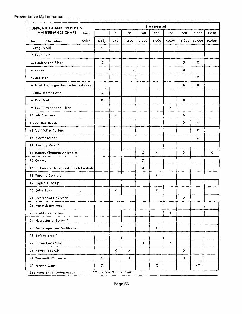
Preventative Maintenance
Page 56

Preventive Maintenance
Item 1Check the oil level daily before starting the engine. Add oil, if necessary, to bring it to the proper level on the dipstick.Select the proper grade of oil in accordance with the instructions in the Lubricating Oil Specifications. It is recommendedthat new engines be started with 100 hour oil change periods. The drain interval may then be gradually increased, ordecreased, following the recommendations of an independent oil analysis laboratory or the oil supplier (based upon theoil sample analysis) until the most practical oil change period has been established.
Item 2Install new engine oil filter elements and gaskets each time the engine oil is changed. Check for oil leaks after startingthe engine. If the engine is equipped with a governor oil filter, change the element every 1,000 hours.
Item 3Check the coolant level daily and maintain it near the top of the heat exchanger tank or the radiator upper tank.
Clean the cooling system every 1,000 hours or 30,000 miles using a good radiator cleaning compound in accordancewith the instructions on the container. After the cleaning operation, rinse the cooling system thoroughly with fresh water.Then fill the system with soft water, adding a good grade of rust inhibitor or a high boiling point type antifreeze (refer toEngine Coolant). With the use of a proper antifreeze or rust inhibitor, this interval may be lengthened until, normally, thiscleaning is done only in the spring or fall. The length of this interval will, however, depend upon an inspection for rust orother deposits on the internal walls of the cooling system. When a thorough cleaning of the cooling system is required, itshould be reverse-flushed.
If the cooling system is protected by a coolant filter and conditioner, the filter element should be changed every 500hours or 15,000 miles.
Item 4Inspect all of the cooling system hoses at least once every 500 hours or 15,000 miles for signs of deterioration. Replacethe hoses if necessary.
Items 1 and 2 Items 3 and 4
Page 57

Preventive Maintenance
Item 5Inspect the exterior of the radiator core every 1,000 hours or 30,000 miles and, if necessary, clean it with a quality greasesolvent such as mineral spirits and compressed air. Do not use fuel oil, kerosene or gasoline. It may be necessary toclean the radiator more frequently if the engine is being operated in extremely dusty or dirty areas.
Item 6Every 500 hours drain the water from the heat exchanger raw water inlet and outlet tubes. Then remove the zincelectrodes from the inlet side of the raw water pump and the heat exchanger. Clean the electrodes with a wire brush or,if worn excessively, replace with new electrodes. To determine the condition of a used electrode, strike it sharply againsta hard surface; a weakened electrode will break.
Drain the cooling system, disconnect the raw water pipes at the outlet side of the heat exchanger and remove theretaining cover every 1,000 hours and inspect the heat exchanger core. If a considerable amount of scale or depositsare present, contact an authorized Detroit Diesel Allison Service Outlet.
Item 5
Item 6
Item 7Check the prime on the raw water pump; the engine shouldnot be operated with a dry pump. Prime the pump, ifnecessary, by removing the pipe plug provided in the pumpinlet elbow and adding water. Reinstall the plug.
Item 8Keep the fuel tank filled to reduce condensation to aminimum. Select the proper grade of fuel in accordancewith the Diesel Fuel Oil Specifications.
Open the drain at the bottom of the fuel tank every 500hours or 15,000 miles to drain off any water or sediment.
Item 9Install new elements every 300 hours or 9,000 miles orwhen plugging is indicated. A method of determining whenelements are plugged to the extent that they should bechanged is based on he fuel pressure at the cylinder headfuel inlet manifold and the inlet restriction at the fuel pump.
Page 58

Preventive Maintenance
In a clean system, the maximum pump inlet restriction must not exceed 6 inches of mercury. At normal operatingspeeds (1800-2800 rpm), the fuel pressure is 45 to 70 psi (310 to 483 kPa). Change the fuel filter elements wheneverthe inlet restriction (suction ) at the fuel pump reaches 12 inches of mercury at normal operating speeds and wheneverthe fuel pressure at the inlet manifold falls to 45 psi (310 kPa).
Item 10Remove the dirty oil and sludge from the oil bath-type air cleaner cups and center tubes every 8 hours or less if operatingconditions warrant. Wash the cups and elements in clean fuel oil and refill the cups to the level mark with the samegrade of heavy duty oil as used in the engine. The frequency of servicing may be varied to suit local dust conditions.
It is recommended that the body and fixed element in the heavy-duty oil bath type air cleaner be serviced every 500hours, 15,000 miles or as conditions warrant.
Clean or replace the element in the dry-type air cleaner when the restriction indicator instrument indicates high restrictionor when a water manometer reading at the air inlet housing indicates the maximum allowable air inlet restriction (refer tothe Air Inlet Restriction chart in the Trouble Shooting section). Refer to the instructions in the Air System section forservicing the dry-type air cleaner.
Item 9
Item 10
Item 11With the engine running, check for flow of air from the airbox drain tubes every 1,000 hours or 30,000 miles. If thetubes are clogged, remove, clean and reinstall the tubes.The air box drain tubes should be cleaned periodicallyeven though a clogged condition is not apparent. If theengine is equipped with an air box drain tank, drain thesediment periodically. If the engine is equipped with an airbox drain check valve, replace the valve every 500 hoursor 15,000 miles.
Item 12Clean the externally mounted crankcase breatherassemblies every 1,000 hours or 30,000 miles. Thiscleaning period may be reduced or lengthened according toseverity of service. Clean the internally mounted breatherpads at time of engine overhaul, or sooner if excessivecrankcase pressure is observed.
Item 11
Page 59

Preventive Maintenance
Remove the crankcase breather from the engine and wash the steel mesh pad (element) in fuel oil and dry it withcompressed air. Reinstall the breather assembly.
Clean the breather cap, mounted on the valve rocker cover, in clean fuel oil every time the engine oil is changed.
Item 13Inspect the blower screen and gasket assemblies every 1,000 hours or 30,000 miles and, if necessary, clean the screensin fuel oil and dry them with compressed air.
Reinstall the screen and gasket assemblies with the screen side of the assemblies toward the blower. Inspect forevidence of blower seal leakage.
Item 14The electrical starting motor is lubricated at the time of original assembly. Oil can be added to the oil wicks, whichproject through each bushing and contact the armature shaft, by removing the pipe plugs on the outside of the motor.The wicks should be lubricated whenever the starting-motor is taken off the engine or disassembled.
The Sprag overrunning clutch drive mechanism should be lubricated with a few drops of light engine oil whenever thestarting motor is overhauled.
Item 12
Item 13
Item 15Lubricate the alternator bearings or bushings with 5 or 6drops of engine oil at the hinge cap oiler every 200 hoursor-6;000 miles.
Some alternators have a built-in supply of grease, whileothers use sealed bearings. In these latter two cases,additional lubrication is not necessary.
The slip rings and brushes of an alternator can beinspected through the end frame assembly. If the slip ringsare dirty, they should be cleaned with 400 grain or finerpolishing cloth. Never use emery cloth to clean slip rings.Hold the polishing cloth against the slip rings with thealternator in operation and blow away all dust after thecleaning operation.
Item 14Page 60

Preventive Maintenance
Item 15 Item 17
Item 15If the slip rings are rough or out of round, replace them. Inspect the terminals for corrosion and loose connections andthe wiring for frayed insulation.
Item 16Check the specific gravity of the electrolyte in each cell of the battery every 100 hours or 3,000 miles. In warm weather,however, it should be checked more frequently due to a more rapid loss of water from the electrolyte. The electrolytelevel should be maintained in accordance with the battery manufacturer's recommendations.
Item 17Lubricate the tachometer drive every 100 hours or 3,000 miles with an all purpose grease at the grease fitting. Attemperatures above +30°F (-1 C), use a No. 2 grade grease. Use a No. I grade grease below this temperature.
Item 18Lubricate the throttle control mechanism every 200 hours or 6,000 miles with an all purpose grease. At temperaturesabove +30°F (-1°C), use a No. 2 grade grease. Use a No. 1 grade grease below this temperature. Lubricate all othercontrol mechanisms, as required, with engine oil.
Item 19There is no scheduled interval for performing an engine tune-up. As long as the engine performance is satisfactory, notune-up should be needed. Minor adjustments in the valve and injector operating mechanisms, governor, etc. shouldonly be required periodically to compensate for normal wear on parts.
Item 20New drive belts will stretch after the first few hours of operation. Run the engine for 15 seconds to seat the belts andreadjust the tension. Then check the belts and retighten the fan drive, pump drive and battery-charging alternator drivebelts after 1/2 hour or 15 miles and again after 8 hours or 140 miles of operation. Thereafter, check the tension of thedrive belts every 200 hours or 6,000 miles and adjust, if necessary.
Page 61
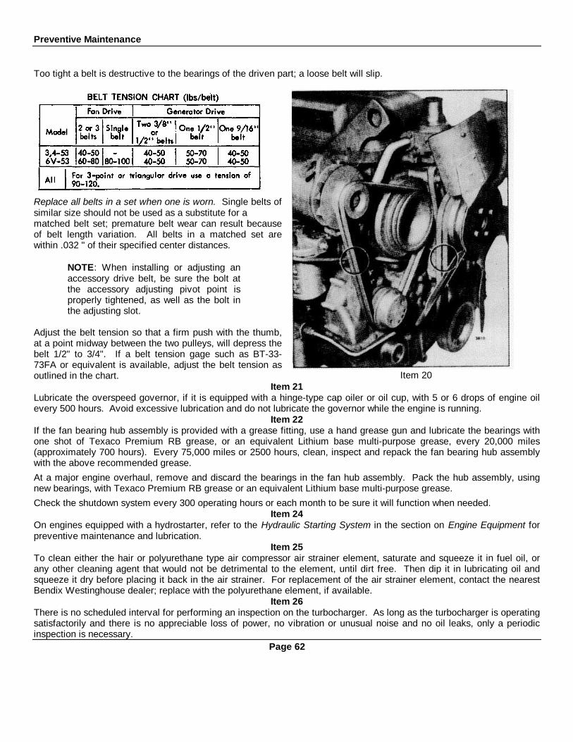
Preventive Maintenance
Too tight a belt is destructive to the bearings of the driven part; a loose belt will slip.
Replace all belts in a set when one is worn. Single belts ofsimilar size should not be used as a substitute for amatched belt set; premature belt wear can result becauseof belt length variation. All belts in a matched set arewithin .032 " of their specified center distances.
NOTE: When installing or adjusting anaccessory drive belt, be sure the bolt atthe accessory adjusting pivot point isproperly tightened, as well as the bolt inthe adjusting slot.
Adjust the belt tension so that a firm push with the thumb,at a point midway between the two pulleys, will depress thebelt 1/2" to 3/4". If a belt tension gage such as BT-33-73FA or equivalent is available, adjust the belt tension asoutlined in the chart. Item 20
Item 21Lubricate the overspeed governor, if it is equipped with a hinge-type cap oiler or oil cup, with 5 or 6 drops of engine oilevery 500 hours. Avoid excessive lubrication and do not lubricate the governor while the engine is running.
Item 22If the fan bearing hub assembly is provided with a grease fitting, use a hand grease gun and lubricate the bearings withone shot of Texaco Premium RB grease, or an equivalent Lithium base multi-purpose grease, every 20,000 miles(approximately 700 hours). Every 75,000 miles or 2500 hours, clean, inspect and repack the fan bearing hub assemblywith the above recommended grease.At a major engine overhaul, remove and discard the bearings in the fan hub assembly. Pack the hub assembly, usingnew bearings, with Texaco Premium RB grease or an equivalent Lithium base multi-purpose grease.Check the shutdown system every 300 operating hours or each month to be sure it will function when needed.
Item 24On engines equipped with a hydrostarter, refer to the Hydraulic Starting System in the section on Engine Equipment forpreventive maintenance and lubrication.
Item 25To clean either the hair or polyurethane type air compressor air strainer element, saturate and squeeze it in fuel oil, orany other cleaning agent that would not be detrimental to the element, until dirt free. Then dip it in lubricating oil andsqueeze it dry before placing it back in the air strainer. For replacement of the air strainer element, contact the nearestBendix Westinghouse dealer; replace with the polyurethane element, if available.
Item 26There is no scheduled interval for performing an inspection on the turbocharger. As long as the turbocharger is operatingsatisfactorily and there is no appreciable loss of power, no vibration or unusual noise and no oil leaks, only a periodicinspection is necessary.
Page 62
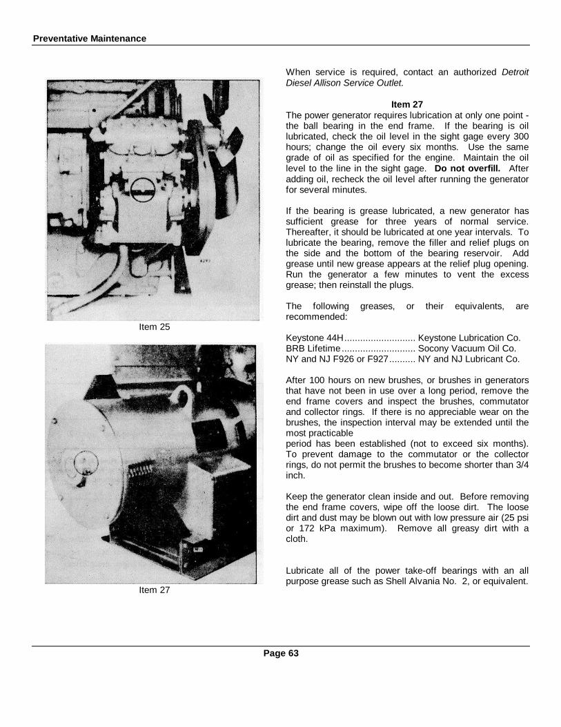
Preventative Maintenance
Item 25
Item 27
When service is required, contact an authorized DetroitDiesel Allison Service Outlet.
Item 27The power generator requires lubrication at only one point -the ball bearing in the end frame. If the bearing is oillubricated, check the oil level in the sight gage every 300hours; change the oil every six months. Use the samegrade of oil as specified for the engine. Maintain the oillevel to the line in the sight gage. Do not overfill. Afteradding oil, recheck the oil level after running the generatorfor several minutes.
If the bearing is grease lubricated, a new generator hassufficient grease for three years of normal service.Thereafter, it should be lubricated at one year intervals. Tolubricate the bearing, remove the filler and relief plugs onthe side and the bottom of the bearing reservoir. Addgrease until new grease appears at the relief plug opening.Run the generator a few minutes to vent the excessgrease; then reinstall the plugs.
The following greases, or their equivalents, arerecommended:
Keystone 44H........................... Keystone Lubrication Co.BRB Lifetime............................ Socony Vacuum Oil Co.NY and NJ F926 or F927.......... NY and NJ Lubricant Co.
After 100 hours on new brushes, or brushes in generatorsthat have not been in use over a long period, remove theend frame covers and inspect the brushes, commutatorand collector rings. If there is no appreciable wear on thebrushes, the inspection interval may be extended until themost practicableperiod has been established (not to exceed six months).To prevent damage to the commutator or the collectorrings, do not permit the brushes to become shorter than 3/4inch.
Keep the generator clean inside and out. Before removingthe end frame covers, wipe off the loose dirt. The loosedirt and dust may be blown out with low pressure air (25 psior 172 kPa maximum). Remove all greasy dirt with acloth.
Lubricate all of the power take-off bearings with an allpurpose grease such as Shell Alvania No. 2, or equivalent.
Page 63

Preventive Maintenance
Lubricate sparingly to avoid getting grease on the clutchfacing.
Open the cover on the side of the clutch housing (8" and10" diameter clutch) and lubricate the clutch release sleevecollar through the grease fitting every 8 hours. On the 11-1/2" diameter clutch, lubricate the collar through the fittingon the side of the clutch housing every 8 hours.
Lubricate the clutch drive shaft pilot bearing through thefitting in the outer end of the drive shaft (8" and 10 "diameter clutch power take-offs) every 50 hours ofoperation. One or two strokes with a grease gun should besufficient. The clutch drive shaft pilot bearing used withthe 11-1/2" diameter clutch power take-off is prelubricatedand does not require lubrication.
Lubricate the clutch drive shaft roller bearings through thegrease fitting in the clutch housing every 50 hours undernormal operating conditions (not continuous) and moreoften under severe operating conditions or continuousoperation. Lubricate the clutch release shaft through thefittings at the rear of the housing every 500 hours ofoperation.
Lubricate the clutch levers and links sparingly with engine oil every 500 hours of operation. Remove the inspection holecover on the clutch housing and lubricate the clutch release levers and pins with a hand oiler. To avoid getting oil on theclutch facing, do not over lubricate the clutch release levers and pins.Check the clutch facing for wear every 500 hours. Adjust the clutch if necessary.
Item 29Check the oil level in the Torqmatic converter and supply tank daily. The oil level must be checked while the converter isoperating, the engine idling and the oil is up to operating temperature (approximately 200° F or 93 ° C). If the converteris equipped with an input disconnect clutch, the clutch must be engaged.Check the oil level after running the unit a few minutes. The oil level should be maintained at the proper level on thedipstick. If required, add hydraulic transmission fluid type "C-2" (Table 1). Do not overfill the converter as too much oilwill cause foaming and high oil temperature.The oil should be changed every 500 hours of operation. Also, the oil should be changed whenever it shows traces ofdirt or effects of high operating temperature as evidenced by discoloration or strong odor. If the oil shows metalcontamination, contact an authorized Detroit Diesel Allison Service Outlet as this usually requires disassembly. Undersevere operating conditions, the oil should be changed more often.The converter oil breather, located on the oil level indicator (dipstick), should be cleaned each time the converter oil ischanged. This can be accomplished by allowing the breather to soak in a solvent, then drying it with compressed air.
OIL RECOMMENDATIONSPrevailingAmbient
TemperatureRecommended Oil
SpecificationAbove-10°F (-230C) Hydraulic Transmission Fluid, Type C-2.
Hydraulic Transmission Fluid, Type C-2. Aux-Below iliory preheat required to raise temperature--10°F(--23°C) in the sump to a temperature above -10°F. (-23°C)
TABLE 1
Page 64Preventive Maintenance

Item 30
The full-flow oil filter element should be removed, the shell cleaned and a new element and gasket installed each timethe converter oil is changed. Lubricate the input clutch release bearing and ball bearing every 50 hours with an allpurpose grease through the grease fittings provided on the clutch housing. This time interval may vary depending uponthe operating conditions. Over-lubrication will cause grease to be .thrown on the clutch facing, causing the clutch to slip.
Item 30WARNER MARINE GEAR:Check the oil level daily. Start and run the engine at idle speed for a few minutes to fill the lubrication system. Stop theengine. Then immediately after stopping the engine, check the oil level in the marine gear. Bring the oil level up to theproper level on the dipstick. Use the same grade of lubricating oil that is used in the engine. Do not overfill.
Change the oil every 200 hours. After draining the oil from the unit, clean the removable oil screen thoroughly beforerefilling the marine gear with oil.
TWIN DISC MARINE GEAR:Check the marine gear oil level daily. Check the oil level with the engine running at low idle speed and the gear inneutral. Keep the oil up to the proper level on the dipstick. Use oil of the same heavy-duty grade and viscosity that isused in the engine.
Change the oil every 200 hours. Remove and clean the oil inlet strainer screen after draining the oil and before refillingthe marine gear. The strainer is located in the sump at the lower end of the pump suction line. When refilling after an oildrain, bring the oil up to the proper level on the dipstick (approximately 5 quarts or 4.74 litres).
Page 65

Fuel, Oil and Coolant Specifications
DETROIT DIESEL FUEL OIL SPECIFICATIONSGENERAL CONSIDERATIONSThe quality of fuel oil used for high-speed diesel engine operation is a very important factor in obtainingsatisfactory engine performance, long engine life, and acceptable exhaust.Fuel selected should be completely distilled material. That is, the -fuel should show at least 98 percent by volumerecovery when subjected to ASTM D-86 distillation. Fuels marketed to meet Federal Specification VV-F-800 (grades DF-1 and DF-2) and ASTM Designation D-975 (grades 1-D and 2-D) meet the completely distilled criteria. Some of thegeneral properties of VV-F-800 and ASTM D-975 fuels are shown below.
FEDERAL SPECIFICATION & ASTM DIESEL FUEL PROPERTIESResidual fuels and domestic furnace oils are not consideredsatisfactory for Detroit Diesel engines: however, some may beacceptable. (See "DETROIT DIESEL FUEL OILSPECIFICATIONS.")
NOTE: Detroit Diesel Allison does notrecommend the use of drained lubricating oilas a diesel fuel oil. Furthermore, DetroitDiesel will not be responsible for any enginedetrimental effects which it determinesresulted from this practice.
All diesel fuel oil contains a certain amount of sulfur. Too higha sulfur content results in excessive cylinder wear due to acidbuild-up in the lubricating oil. For most satisfactory enginelife, fuels containing less than 0.5% sulfur should be used.
Fuel oil should be clean and free of contamination. Storage tanks should be inspected regularly for dirt, water or water-emulsion sludge, and cleaned if contaminated. Storage instability of the fuel can lead to the formation of varnish orsludge in the tank. The presence of these contaminants from storage instability must be resolved with the fuel supplier.
DETROIT DIESEL FUEL OIL SPECIFICATIONSDetroit Diesel Allison designs, develops, and manufactures commercial diesel engines to operate on diesel fuelsclassified by the ASTM as Designation D-975 (grades I-D and 2-D). These grades are very similar to grades DF-I andDF-2 of Federal Specification VV-F-800. Residual fuels and furnace oils, generally, are not considered satisfactory forDetroit Diesel engines. In some regions, however, fuel suppliers may distribute one fuel that is marketed as either dieselfuel (ASTM D-975) or domestic heating fuel (ASTM D-396) sometimes identified as furnace oil. In this case, the fuelshould be investigated to determine whether the properties conform with those shown in the "FUEL OIL SELECTIONCHART" presented in this specification.The "FUEL OIL SELECTION CHART" also will serve as a guide in the selection of the proper fuel for variousapplications. The fuels used must be clean, completely distilled, stable, and non-corrosive, DISTILLATION RANGE,CETANE NUMBER, and SULFUR CONTENT are three of the most important properties of diesel fuels that must becontrolled to insure optimum combustion and minimum wear.Engine speed, load, and ambient temperature influence the selection of fuels with respect to distillation range and cetanenumber. The sulfur content of the fuel must be as low as possible to avoid excessive deposit formation, premature wear,and to minimize the sulfur dioxide exhausted into the atmosphere.To assure that the fuel you use meets the required properties, enlist the aid of a reputable fuel oil supplier.The responsibility for clean fuel lies with the fuel supplier as well as the operator. During cold weather engine operation,the cloud point (the temperature at which wax crystals begin to form in diesel fuel) should be 10°F (6°C) below the lowestexpected fuel temperature to prevent clogging of the fuel filters by wax crystals.At temperatures below -20°F (-29°C), consult an authorized Detroit Diesel Allison service outlet, since particularattention must be given to the cooling system, lubricating system, fuel system, electrical system, and cold weatherstarting aids for efficient engine starting and operation.FUEL OIL SELECTION CHART
NOTE: When prolonged idling periods orcold weather conditions below 32°F (0°C)are encountered. the use of lighter distillatefuels may be more practical. The sameconsideration must be made when operatingat altitudes above 5,000 ft.
Page 66

Fuel, Oil and Coolant Specifications
DETROIT DIESEL FUEL OIL SPECIFICATIONSGENERAL CONSIDERATIONSAll diesel engines require heavy-duty lubricating oils. Basic requirements of such oils are:Lubricating Quality High Heat Resistance Control of ContaminantsLUBRICATING QUALITY. The reduction of friction and wear by maintaining an oil film between moving parts is the primary requisiteof a lubricant. Film thickness and its ability to prevent metal-to-metal contact of moving parts is related to oil viscosity. Theoptimums for Detroit Diesel engines are SAE 40 or 30 weight.HIGH HEAT RESISTANCE. Temperature is the most important factor in determining the rate at which deterioration or oxidation ofthe lubricating oil will occur. The oil should have adequate thermal stability at elevated temperatures, thereby precluding formation ofharmful carbonaceous and/or ash deposits.CONTROL OF CONTAMINANTS. The piston and compression rings must ride on a film of oil to minimize wear and prevent cylinderseizure. At normal rates of consumption, oil reaches a temperature zone at the upper part of the piston where rapid oxidation andcarbonization can 'occur. In addition, as oil circulates through the engine, it is continuously contaminated by soot, acids, and wateroriginating from combustion. Until they are exhausted, detergent and dispersant additives aid in keeping sludge and varnish fromdepositing on engine parts. But such additives in excessive quantities can result in detrimental ash deposits. If abnormal amounts ofinsoluble deposits form, particularly on the piston in the compression ring area, early engine failure may result. Oil that is carried upthe cylinder liner wall is normally consumed during engine operation. The oil and additives leave carbonaceous and/or ash depositswhen subjected to the elevated temperatures of the combustion chamber. The amount of deposits is influenced by the oilcomposition, additive content, engine temperature. and oil consumption rate.
DETROIT DIESEL LUBRICATING OIL SPECIFICATIONSOIL QUALITY
OIL QUALITY is the responsibility of the oil supplier. (The term oil supplier is applicable to refiners, blenders, and rebranders ofpetroleum products, and does not include distributors of such products.)There are hundreds of commercial crankcase oils marketed today. Obviously, engine manufacturers or users cannot completelyevaluate the numerous commercial oils. The selection of a suitable lubricant in consultation with a reliable oil supplier, observance ofhis oil drain recommendations (based on used oil sample analysis and experience) and proper filter maintenance, will provide thebest assurance of satisfactory oil performance.Detroit Diesel Allison lubricant recommendations are based on general experience with current lubricants of various types and giveconsideration to the commercial lubricants presently available.
RECOMMENDATIONDetroit Diesel engines have given optimum performance and experienced the longest service life with the following oil performancelevels having the ash and zinc limits shown:
Former Military API Letter CodeIdentification Service Classification SAE GradeMIL-L-2104B/1964MS *
CC/SC 40 or 30 •
Supplement 1** CB 40 or 30 •*Military Specification MIL-L-2104B is obsolete and new developed products can no longer be qualified to meet this performancelevel. However, many lubricants formulated to meet the performance criteria of MIL-L-2104B/1964MS are still being marketed.Detroit Diesel engines have given optimum performance and experienced the longest service life using MIL-L-2104B/1964MSlubricants. The majority of MIL-L-2104B/1964MS lubricants have a sulfated ash content between 0.55 and 0.85 percent by weight.**Supplement I oils have a history of very satisfactory performance in Detroit Diesel engines. Supplement 1oils have a relatively lowash content. However, the Supplement I oil specification is obsolete and new products cannot be qualified to meet this performancelevel. Some older formulations are still distributed and used by Detroit Diesel engine customers.• SAE 40 grade oil has performed satisfactorily and is recommended in Detroit Diesel engines. Obviously, the expected ambienttemperatures and engine cranking capability must be considered by the engine owner/operator when selecting the proper grade ofoil. Only when the ambient temperatures and engine cranking capabilities result in difficult starting should SAE 30 grade oil beused.
ASH LIMITThe sulfated ash (ASTM D-874) limit of all the lubricants recommended or selected as alternates for use in Detroit Diesel enginesshall not exceed 1.000 percent by weight, except lubricants that contain only barium detergent-dispersant salts where 1.500 percentby weight is allowed. Lubricants having a sulfated ash content between 0.55 and 0.85 percent by weight have a history of excellentperformance in Detroit Diesel engines. Lubricants having a sulfated ash content greater than 0.85 percent by weight are prone toproduce greater deposit levels in the ring belt and exhaust valve areas of the engine.
Page 67
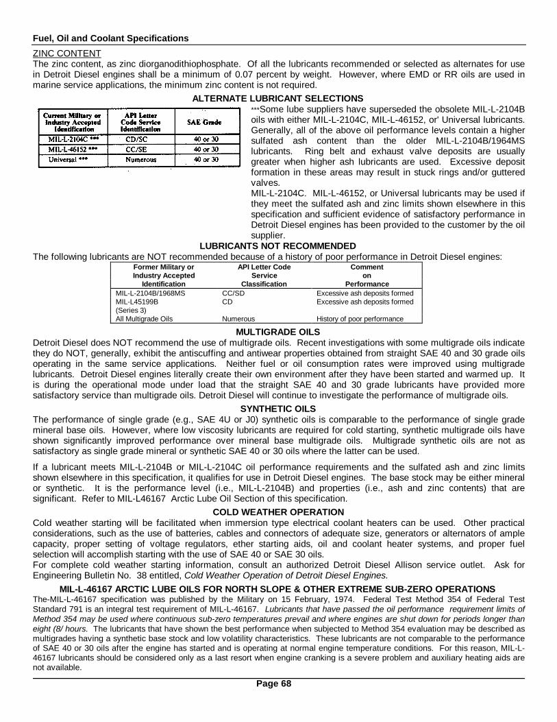
Fuel, Oil and Coolant Specifications
ZINC CONTENTThe zinc content, as zinc diorganodithiophosphate. Of all the lubricants recommended or selected as alternates for usein Detroit Diesel engines shall be a minimum of 0.07 percent by weight. However, where EMD or RR oils are used inmarine service applications, the minimum zinc content is not required.
ALTERNATE LUBRICANT SELECTIONS***Some lube suppliers have superseded the obsolete MIL-L-2104Boils with either MIL-L-2104C, MIL-L-46152, or' Universal lubricants.Generally, all of the above oil performance levels contain a highersulfated ash content than the older MIL-L-2104B/1964MSlubricants. Ring belt and exhaust valve deposits are usuallygreater when higher ash lubricants are used. Excessive depositformation in these areas may result in stuck rings and/or gutteredvalves.MIL-L-2104C. MIL-L-46152, or Universal lubricants may be used ifthey meet the sulfated ash and zinc limits shown elsewhere in thisspecification and sufficient evidence of satisfactory performance inDetroit Diesel engines has been provided to the customer by the oilsupplier.
LUBRICANTS NOT RECOMMENDEDThe following lubricants are NOT recommended because of a history of poor performance in Detroit Diesel engines:
Former Military or API Letter Code CommentIndustry Accepted Service on
Identification Classification PerformanceMIL-L-2104B/1968MS CC/SD Excessive ash deposits formedMIL-L45199B CD Excessive ash deposits formed(Series 3)All Multigrade Oils Numerous History of poor performance
MULTIGRADE OILSDetroit Diesel does NOT recommend the use of multigrade oils. Recent investigations with some multigrade oils indicatethey do NOT, generally, exhibit the antiscuffing and antiwear properties obtained from straight SAE 40 and 30 grade oilsoperating in the same service applications. Neither fuel or oil consumption rates were improved using multigradelubricants. Detroit Diesel engines literally create their own environment after they have been started and warmed up. Itis during the operational mode under load that the straight SAE 40 and 30 grade lubricants have provided moresatisfactory service than multigrade oils. Detroit Diesel will continue to investigate the performance of multigrade oils.
SYNTHETIC OILSThe performance of single grade (e.g., SAE 4U or J0) synthetic oils is comparable to the performance of single grademineral base oils. However, where low viscosity lubricants are required for cold starting, synthetic multigrade oils haveshown significantly improved performance over mineral base multigrade oils. Multigrade synthetic oils are not assatisfactory as single grade mineral or synthetic SAE 40 or 30 oils where the latter can be used.
If a lubricant meets MIL-L-2104B or MIL-L-2104C oil performance requirements and the sulfated ash and zinc limitsshown elsewhere in this specification, it qualifies for use in Detroit Diesel engines. The base stock may be either mineralor synthetic. It is the performance level (i.e., MIL-L-2104B) and properties (i.e., ash and zinc contents) that aresignificant. Refer to MIL-L46167 Arctic Lube Oil Section of this specification.
COLD WEATHER OPERATIONCold weather starting will be facilitated when immersion type electrical coolant heaters can be used. Other practicalconsiderations, such as the use of batteries, cables and connectors of adequate size, generators or alternators of amplecapacity, proper setting of voltage regulators, ether starting aids, oil and coolant heater systems, and proper fuelselection will accomplish starting with the use of SAE 40 or SAE 30 oils.For complete cold weather starting information, consult an authorized Detroit Diesel Allison service outlet. Ask forEngineering Bulletin No. 38 entitled, Cold Weather Operation of Detroit Diesel Engines.
MIL-L-46167 ARCTIC LUBE OILS FOR NORTH SLOPE & OTHER EXTREME SUB-ZERO OPERATIONSThe-MIL-L-46167 specification was published by the Military on 15 February, 1974. Federal Test Method 354 of Federal TestStandard 791 is an integral test requirement of MIL-L-46167. Lubricants that have passed the oil performance requirement limits ofMethod 354 may be used where continuous sub-zero temperatures prevail and where engines are shut down for periods longer thaneight (8/ hours. The lubricants that have shown the best performance when subjected to Method 354 evaluation may be described asmultigrades having a synthetic base stock and low volatility characteristics. These lubricants are not comparable to the performanceof SAE 40 or 30 oils after the engine has started and is operating at normal engine temperature conditions. For this reason, MIL-L-46167 lubricants should be considered only as a last resort when engine cranking is a severe problem and auxiliary heating aids arenot available.
Page 68

Fuel, Oil and Coolant Specifications
EMD OR RR OILSLubricants specified by Electro-Motive Division of General Motors Corporation (EMD) are special lubricants. Generally,these may be described as SAE 40 fluids that possess low Viscosity Index (VI) properties and do not contain any or verylow concentrations of zinc ingredients. They are identified by industry as EMD or railroad (RR) oils. They are anapproved option for Series 149 engines in all marine appilications and for all other model Detroit Diesel engines used forauxiliary power in marine service applications.
OIL CHANGESOil change intervals are dependent upon the various operating conditions of the engines and the sulfur content of thediesel fuel used. Oil drain intervals in all service applications may be increased or decreased with experience using aspecific lubricant, while also considering the recommendations of the oil supplier. Generally, the sulfur content of dieselfuels supplied throughout the U.S.A. and Canada are low (i.e., less than 0.5 per cent by weight-ASTM D-129 or D-1552or D-2622). Fuels distributed in some overseas locations may contain higher concentrations of sulfur, the use of whichwill require reduced lube oil drain intervals.
Highway Trucks & Inter-City Buses (Series 53, 71, and 92 Naturally Aspirated and Turbo-charged Engines)For highway trucks and buses, used for inter-city operation, the oil change interval is 100,000 miles. The drain intervalmay be extended beyond this point if supported by the results obtained from used lube oil analysis; it is recommendedthat you consult with your lube oil supplier in establishing any drain interval exceeding 100,000 miles.
City Transit Coaches and Pick-Up and Delivery Truck Service (Series 53, 71, and 92 Naturally Aspirated andTurbocharged EnginesFor city transit coaches and pick-up and delivery truck service. the oil change interval is 12,500 miles. The oil draininterval may be extended beyond 12,500 miles if supported by used oil analyses.
Industrial and Marine (Series 53, 71, and 92 Naturally Aspirated and Turbo-charged Engines)Series 53, 71, and 92 engines, in industrial and marine service, should be started with 150-hour oil change periods. Theoil drain intervals may be extended if supported by used oil analyses.
Large Industrial and Marine (Series 149 Naturally Aspirated and Turbocharged Engines)The recommended oil change period for naturally aspirated Series 149 engines is 500 hours, while the change period forturbocharged Series 149 engines is 300 hours. These drain intervals may be extended if supported by used oil analyses.
Used Lube Oil Analysis Warning ValuesThe presence of ethylene glycol in the oil is damaging to the engine. Its presence and need for an oil change and forcorrective maintenance action may be confirmed by glycol detector kits which are commercially available. Fuel dilutionof the oil may result from loose fuel connections or from prolonged engine idling. A fuel dilution exceeding 2.5 percentby volume indicates an immediate need for an oil change and corrective maintenance action. Fuel dilution may beconfirmed by ASTM D-322 test procedure performed by oil suppliers or independent laboratories. In addition to the aboveconsiderations, if any of the following occur, the oil should be changed:
1. The viscosity at 1000 F. of a used oil sample is 40 percent greater than the viscosity of the unused oil measured atthe same temperature (ASTM D-445 and D-2161).
2. The iron content is greater than 150 parts per million.3. The pentane insolubles (total contamination) exceed 1.00 percent by weight (ASTM D-893).4. The total base number (TBN) is less than 1.0 (ASTM D-664). Note: The sulfur content of the diesel fuel used will
influence the alkalinity of the lube oil. With high sulfur fuels, the oil drain interval will have to be shortened to avoidexcessive acidity in the lube oil.
LUBE OIL FILTER ELEMENT CHANGESFull-Flow FiltersA full-flow oil filtration system is used in all Detroit Diesel engines. To insure against physical deterioration of the filterelement, it should be replaced at a maximum of 25,000 miles for on-highway vehicles or at each oil change period,whichever occurs first. For all other applications, the filter should be replaced at a maximum of 500 hours or at each oilchange period, whichever occurs first.
By-Pass FiltersAuxiliary by-pass lube oil filters are not required on Detroit Diesel engines.
Page 69
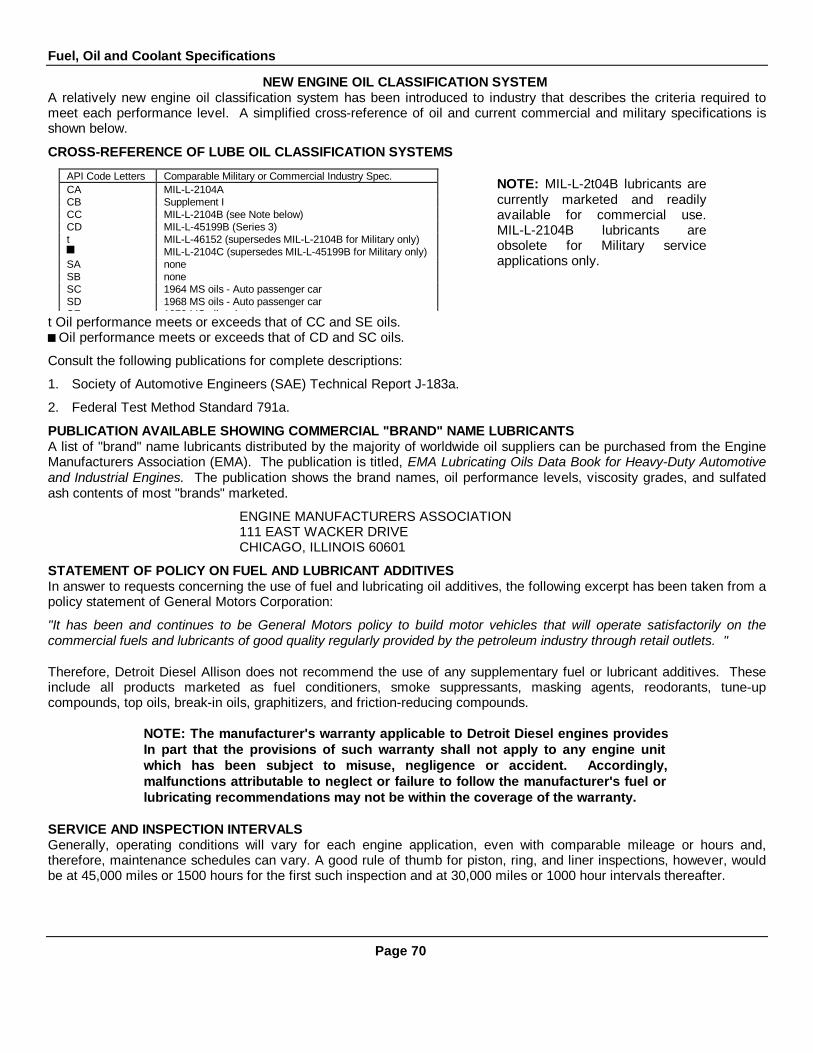
Fuel, Oil and Coolant Specifications
NEW ENGINE OIL CLASSIFICATION SYSTEMA relatively new engine oil classification system has been introduced to industry that describes the criteria required tomeet each performance level. A simplified cross-reference of oil and current commercial and military specifications isshown below.
CROSS-REFERENCE OF LUBE OIL CLASSIFICATION SYSTEMS
NOTE: MIL-L-2t04B lubricants arecurrently marketed and readilyavailable for commercial use.MIL-L-2104B lubricants areobsolete for Military serviceapplications only.
t Oil performance meets or exceeds that of CC and SE oils. Oil performance meets or exceeds that of CD and SC oils.
Consult the following publications for complete descriptions:
1. Society of Automotive Engineers (SAE) Technical Report J-183a.
2. Federal Test Method Standard 791a.
PUBLICATION AVAILABLE SHOWING COMMERCIAL "BRAND" NAME LUBRICANTSA list of "brand" name lubricants distributed by the majority of worldwide oil suppliers can be purchased from the EngineManufacturers Association (EMA). The publication is titled, EMA Lubricating Oils Data Book for Heavy-Duty Automotiveand Industrial Engines. The publication shows the brand names, oil performance levels, viscosity grades, and sulfatedash contents of most "brands" marketed.
ENGINE MANUFACTURERS ASSOCIATION111 EAST WACKER DRIVECHICAGO, ILLINOIS 60601
STATEMENT OF POLICY ON FUEL AND LUBRICANT ADDITIVESIn answer to requests concerning the use of fuel and lubricating oil additives, the following excerpt has been taken from apolicy statement of General Motors Corporation:
"It has been and continues to be General Motors policy to build motor vehicles that will operate satisfactorily on thecommercial fuels and lubricants of good quality regularly provided by the petroleum industry through retail outlets. "
Therefore, Detroit Diesel Allison does not recommend the use of any supplementary fuel or lubricant additives. Theseinclude all products marketed as fuel conditioners, smoke suppressants, masking agents, reodorants, tune-upcompounds, top oils, break-in oils, graphitizers, and friction-reducing compounds.
NOTE: The manufacturer's warranty applicable to Detroit Diesel engines providesIn part that the provisions of such warranty shall not apply to any engine unitwhich has been subject to misuse, negligence or accident. Accordingly,malfunctions attributable to neglect or failure to follow the manufacturer's fuel orlubricating recommendations may not be within the coverage of the warranty.
SERVICE AND INSPECTION INTERVALSGenerally, operating conditions will vary for each engine application, even with comparable mileage or hours and,therefore, maintenance schedules can vary. A good rule of thumb for piston, ring, and liner inspections, however, wouldbe at 45,000 miles or 1500 hours for the first such inspection and at 30,000 miles or 1000 hour intervals thereafter.
API Code Letters Comparable Military or Commercial Industry Spec.CA MIL-L-2104ACB Supplement ICC MIL-L-2104B (see Note below)CD MIL-L-45199B (Series 3)t MIL-L-46152 (supersedes MIL-L-2104B for Military only)
MIL-L-2104C (supersedes MIL-L-45199B for Military only)SA noneSB noneSC 1964 MS oils - Auto passenger carSD 1968 MS oils - Auto passenger carSE 1972 MS oils - Auto passenger car
Page 70

Fuel, Oil and Coolant Specifications
ENGINE COOLANT
Engine coolant is considered as any solution which is circulated through the engine to provide the means for heat transferfrom the different engine components. In general, water containing various materials in solution is used for this purpose.The function of the coolant is basic to the design and to the successful operation of the engine. Therefore, coolant mustbe carefully selected and properly maintained.
COOLANT REQUIREMENTSA suitable coolant solution must meet the following basicrequirements:I. Provide for adequate heat transfer.2. Provide a corrosion resistant environment within the
cooling system.3. Prevent formation of scale or sludge deposits in the
cooling system.4. Be compatible with the cooling system hose and seal
materials.5. Provide adequate freeze protection during cold
weather operation.The first four requirements are satisfied by combining asuitable water with reliable inhibitors. When operatingconditions dictate the need for freeze protection, a solutionof suitable water and a permanent antifreeze containingadequate inhibitors will provide a satisfactory coolant.
WATERAny water, whether of drinking quality or not, will produce acorrosive environment in the cooling system. Also, scaledeposits may form on the internal surfaces of the coolingsystem due to the mineral content of the water. Therefore,water selected as a coolant must be properly treated withinhibitors to control corrosion and scale deposition. Todetermine if a particular water is suitable for use as acoolant when properly inhibited, the followingcharacteristics must be considered: the concentration ofchlorides, sulfates, total hardness and dissolved solids.Chlorides and/or sulfates tend to accelerate corrosion,while hardness (percentage of magnesium and calciumpresent) causes deposits of scale. Total dissolved solidsmay cause scale deposits, sludge deposits, corrosion or acombination of these. Chlorides, sulfates, magnesium andcalcium are among but not necessarily all the materialswhich make up dissolved solids. Water, within the limitsspecified in Tables 1 and 2 of Fig. 1, is satisfactory as anengine coolant when proper inhibitors are added.
CORROSION INHIBITORSA corrosive inhibitor is a water soluble chemical compoundwhich protects the metallic surfaces of the cooling systemagainst corrosive attack. Some of the more commonlyused corrosion inhibitors are chromates, borates, nitrates,nitrites and soluble oil.
Fig 1. Water Characteristics
Page 71

Fuel, Oil and Coolant Specifications
Depletion of all types of inhibitors occurs through normal operation. Therefore, strength levels must be maintained bythe addition of inhibitors at prescribed intervals. Always follow the supplier's recommendations on inhibitor usage andhandling.
ChromatesSodium chromate and potassium dichromate are two of the best and most commonly used water system corrosioninhibitors. However, the restrictive use of these materials, due to ecology considerations, has de-emphasized their use infavor of non-chromates. Care should be exercised in handling these materials due to their toxic nature.
Chromate inhibitors should not be used in permanent type antifreeze solutions. Chromium hydroxide, commonly called"green slime", can result from the use of chromate inhibitors with permanent type antifreeze. This material deposits onthe cooling system passages, reducing the heat transfer rate (Fig. 2) and results in engine overheating. Engines whichhave operated with a chromate-inhibited water must be chemically cleaned before the addition of permanent antifreeze.A commercial heavy-duty de-scaler should be used in accordance with the manufacturer's recommendation for thispurpose.
Soluble OilSoluble oil has been used as a corrosion inhibitor for many years. It has, however, required very close attention relativeto the concentration level due to adverse effects on heat transfer if the concentration exceeds 1% by volume. Forexample: 1 1/4% of soluble oil in the cooling system increases fire deck temperature 6% and a 2 1/2% concentrationraises fire deck temperature up to 15%. Soluble oil is not recommended as a corrosion inhibitor.
Non-chromatesNon-chromate inhibitors (borates, nitrates, nitrites, etc.) provide corrosion protection in the cooling system with the basicadvantage that they can be used with either water or a water and permanent antifreeze solution.
INHIBITOR SYSTEMSAn inhibitor system (Fig. 3) is a combination of chemicalcompounds which provide corrosion protection, pH controland water softening ability. Corrosion protection isdiscussed under the heading Corrosion Inhibitors. The pHcontrol is used to maintain an acid-free solution. The watersoftening ability deters formation of mineral deposits.Inhibitor systems are available in various forms such ascoolant filter elements, liquid and dry bulk inhibitoradditives, and as an integral part of permanent antifreeze.
Fig. 2 - Heat Transfer Capacity
Coolant Filter ElementsReplaceable elements are available with various chemical inhibitor systems. Compatibility of the element with otheringredients of the coolant solution cannot always be taken for granted.
Problems have developed from the use of the magnesium lower support plate used by some manufacturers in theircoolant filters. The magnesium plate will be attacked by solutions which will not be detrimental to other metals in thecooling system. The dissolved magnesium will be deposited in the hottest zones of the engine where heat transfer ismost critical. The use of an aluminum or zinc support plate in preference to magnesium is recommended to eliminatethe potential of this type of deposit. High chloride coolants will have a detrimental effect on the water softeningcapabilities of systems using ion-exchange resins. Accumulations of calcium and magnesium ions removed from thecoolant and held captive by the zeolite resin can be released into the coolant by a regenerative process caused by highchloride content solutions.
Page 72
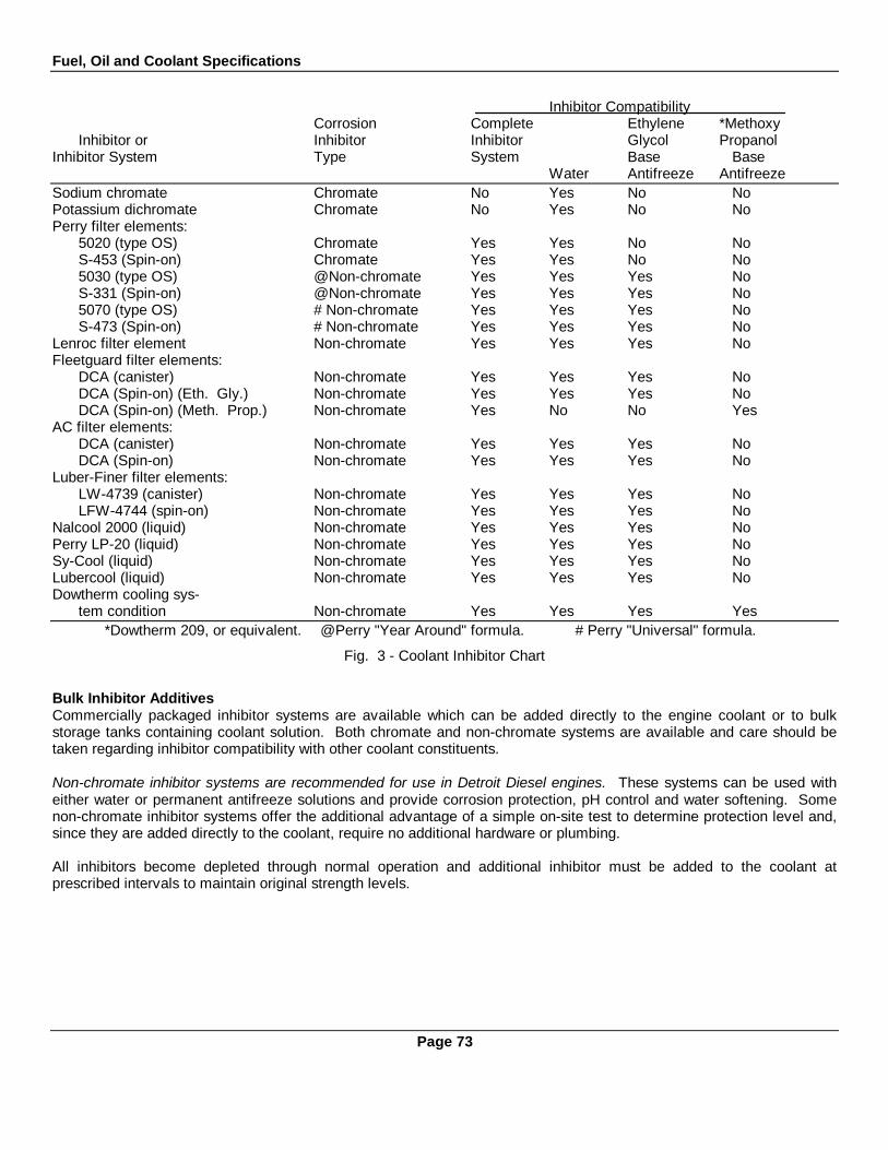
Fuel, Oil and Coolant Specifications
Inhibitor CompatibilityCorrosion Complete Ethylene *Methoxy
Inhibitor or Inhibitor Inhibitor Glycol PropanolInhibitor System Type System Base Base
Water Antifreeze AntifreezeSodium chromate Chromate No Yes No NoPotassium dichromate Chromate No Yes No NoPerry filter elements:
5020 (type OS) Chromate Yes Yes No NoS-453 (Spin-on) Chromate Yes Yes No No5030 (type OS) @Non-chromate Yes Yes Yes NoS-331 (Spin-on) @Non-chromate Yes Yes Yes No5070 (type OS) # Non-chromate Yes Yes Yes NoS-473 (Spin-on) # Non-chromate Yes Yes Yes No
Lenroc filter element Non-chromate Yes Yes Yes NoFleetguard filter elements:
DCA (canister) Non-chromate Yes Yes Yes NoDCA (Spin-on) (Eth. Gly.) Non-chromate Yes Yes Yes NoDCA (Spin-on) (Meth. Prop.) Non-chromate Yes No No Yes
AC filter elements:DCA (canister) Non-chromate Yes Yes Yes NoDCA (Spin-on) Non-chromate Yes Yes Yes No
Luber-Finer filter elements:LW-4739 (canister) Non-chromate Yes Yes Yes NoLFW-4744 (spin-on) Non-chromate Yes Yes Yes No
Nalcool 2000 (liquid) Non-chromate Yes Yes Yes NoPerry LP-20 (liquid) Non-chromate Yes Yes Yes NoSy-Cool (liquid) Non-chromate Yes Yes Yes NoLubercool (liquid) Non-chromate Yes Yes Yes NoDowtherm cooling sys-
tem condition Non-chromate Yes Yes Yes Yes*Dowtherm 209, or equivalent. @Perry "Year Around" formula. # Perry "Universal" formula.
Fig. 3 - Coolant Inhibitor Chart
Bulk Inhibitor AdditivesCommercially packaged inhibitor systems are available which can be added directly to the engine coolant or to bulkstorage tanks containing coolant solution. Both chromate and non-chromate systems are available and care should betaken regarding inhibitor compatibility with other coolant constituents.
Non-chromate inhibitor systems are recommended for use in Detroit Diesel engines. These systems can be used witheither water or permanent antifreeze solutions and provide corrosion protection, pH control and water softening. Somenon-chromate inhibitor systems offer the additional advantage of a simple on-site test to determine protection level and,since they are added directly to the coolant, require no additional hardware or plumbing.
All inhibitors become depleted through normal operation and additional inhibitor must be added to the coolant atprescribed intervals to maintain original strength levels.
Page 73
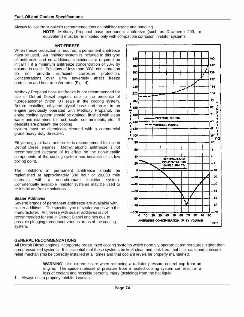
Fuel, Oil and Coolant Specifications
Always follow the supplier's recommendations on inhibitor usage and handling.NOTE: Methoxy Propanol base permanent antifreeze (such as Dowtherm 209, orequivalent) must be re-inhibited only with compatible corrosion inhibitor systems.
ANTIFREEZEWhen freeze protection is required, a permanent antifreezemust be used. An inhibitor system is included in this typeof antifreeze and no additional inhibitors are required oninitial fill if a minimum antifreeze concentration of 30% byvolume is used. Solutions of less than 30%, concentrationdo not provide sufficient corrosion protection.Concentrations over 67% adversely affect freezeprotection and heat transfer rates (Fig. 4).
Methoxy Propanol base antifreeze is not recommended foruse in Detroit Diesel engines due to the presence offluoroelastomer (Viton '0') seals in the cooling system.Before installing ethylene glycol base anti-freeze in anengine previously operated with Methoxy Propanol, theentire cooling system should be drained, flushed with cleanwater and examined for rust, scale, contaminants, etc. Ifdeposits are present, the coolingsystem must be chemically cleaned with a commercialgrade heavy-duty de-scaler.
Ethylene glycol base antifreeze is recommended for use inDetroit Diesel engines. Methyl alcohol antifreeze is notrecommended because of its effect on the non-metalliccomponents of the cooling system and because of its lowboiling point.
The inhibitors in permanent antifreeze should bereplenished at approximately 500 hour or 20,000 mileintervals with a non-chromate inhibitor system.Commercially available inhibitor systems may be used tore-inhibit antifreeze solutions.
Sealer AdditivesSeveral brands of permanent antifreeze are available withsealer additives. The specific type of sealer varies with themanufacturer. Antifreeze with sealer additives is notrecommended for use in Detroit Diesel engines due topossible plugging throughout various areas of the coolingsystem.
GENERAL RECOMMENDATIONSAll Detroit Diesel engines incorporate pressurized cooling systems which normally operate at temperatures higher thannon-pressurized systems. It is essential that these systems be kept clean and leak-free, that filler caps and pressurerelief mechanisms be correctly installed at all times and that coolant levels be properly maintained.
WARNING: Use extreme care when removing a radiator pressure control cap from anengine. The sudden release of pressure from a heated cooling system can result in aloss of coolant and possible personal injury (scalding) from the hot liquid.
1. Always use a properly inhibited coolant.
Page 74

Fuel, Oil and Coolant Specifications
2. Do not use soluble oil.
3. Maintain the prescribed inhibitor strength.
4. Always follow the manufacturer's recommendations on inhibitor usage and handling.
5. If freeze protection is required, always use a permanent antifreeze.
6. Re-inhibit antifreeze with a recommended non-chromate inhibitor system.
7. Do not use a chromate inhibitor with permanent antifreeze.
8. Do not use Methoxy Propanol base antifreeze in Detroit Diesel engines.
9. DO NOT mix ethylene glycol base antifreeze with Methoxy Propanol base antifreeze in the cooling system.
10. Do not use an antifreeze containing sealer additives.
11. Do not use methyl alcohol base antifreeze.
12. Use extreme care when removing the radiator pressure control cap.
Page 75

ENGINE TUNE-UP PROCEDURES
There is no scheduled interval for performing an engine tune-up. As long as the engine performance is satisfactory, notune-up should be needed. Minor adjustments in the valve and injector operating mechanisms, governor, etc. shouldonly be required periodically to compensate for normal wear on parts.
Three types of governors are used. Since each governor has different characteristics, the tune-up procedure variesaccordingly. The three types are:
1. Limiting speed mechanical.
2. Variable speed mechanical.
3. Hydraulic.
The mechanical engine governors are identified by a name plate attached to the governor housing. The letters D.W.-L.S. stamped on the name plate denote a double-weight limiting speed governor. A single-weight variable speedgovernor name plate is stamped S.W.-V.S.
Normally, when performing a tune-up on an engine in service, it is only necessary to check the various adjustments for apossible change in the settings. However, if the cylinder head, governor or injectors have been replaced or overhauled,then certain preliminary adjustments are required before the engine is started.
The preliminary adjustments consist of the first four items in the tune-up sequence. The procedures are the same exceptthat the valve clearance is greater for a cold engine.
To tune-up an engine completely, all of the adjustments are made by following the applicable tune-up sequence givenbelow after the engine has reached the normal operating temperature. Since the adjustments are normally made whilethe engine is stopped, it may be necessary to run the engine between adjustments to maintain normal operatingtemperature.Tune-Up Sequence for Mechanical Governor
CAUTION: Before starting an engine after an engine speed control adjustment or afterremoval of the engine governor cover, the serviceman must determine that the injectorracks move to the no-fuel position when the governor stop lever is placed in the stopposition. Engine overspeed will result if the injector racks cannot be positioned at no fuelwith the governor stop lever.
1. Adjust the exhaust valve clearance.2. Time the fuel injectors.3. Adjust the governor gap.4. Position the injector rack control levers.5. Adjust the maximum no-load speed.6. Adjust the idle speed.7. Adjust the buffer screw.8. Adjust the throttle booster spring (variable speed governor only).9. Adjust the supplementary governing device (if used).
Tune-Up Sequence for Hydraulic Governor1. Adjust the exhaust valve clearance.2. Time the fuel injectors.3. Adjust the fuel rod.4. Position the injector rack control levers.5. Adjust the load limit screw.6. Adjust the speed droop.7. Adjust the maximum no-load speed.
NOTE: Use new valve rocker cover gasket(s)after each tune-up.
Page 77

Engine Tune-Up
EXHAUST VALVE CLEARANCE ADJUSTMENT
The correct exhaust valve clearance at normal engine operating temperature is important for smooth,efficient operation of the engine.
Insufficient valve clearance can result in loss of compression, misfiring cylinders, and eventually burned valve seats andvalve seat inserts. Excessive valve clearance will result in noisy operation,especially in the low speed range.
Whenever the cylinder head is overhauled, the exhaust valves reconditioned or replaced, or the valve operatingmechanism is replaced or disturbed in any way, the valve clearance must first be adjusted to the cold setting to allow fornormal expansion of the engine parts during the engine warm-up period. This will ensure a valve setting which is closeenough to the specified clearance to prevent damage to the valves when the engine is started.
All of the exhaust valves may be adjusted, in firing order sequence, during one full revolution of the crankshaft. Refer tothe General Specifications at the front of the manual for the engine firing order.
TWO CYLINDER VALVE HEADS
Fig 1. Adjusting Valve Clearance (Two-ValveCylinder Head)
Cold Engine1. Place the speed control lever in the idle speed position.
If a stop lever is provided, secure it in the no-fuelposition.
2. Remove the loose dirt from the valve rocker cover(s)and remove the cover(s).
3. Rotate the crankshaft, manually or with the startingmotor, until the injector follower is fully depressed onthe cylinder to be adjusted.
CAUTION: If a wrench is used on thecrankshaft bolt, do not turn the engine ina left-hand direction of rotation as thebolt will be loosened.
4. Loosen the exhaust valve rocker arm push rod locknut.
5. Place a .012" feeler gage, J 9708, between the valve stem and the rocker arm (Fig. 1). Adjust the push rod toobtain a smooth pull on the feeler gage.
6. Remove the feeler gage. Hold the push rod with a 5/16"wrench and tighten the lock nut with a 1/2 "wrench.7. Recheck the clearance. At this time, if the adjustment is correct, the .010" gage will pass freely between the end of
the valve stem and the rocker arm and the .012" gage will not pass through.8. Check and adjust the remaining valves in the same manner as outlined above.
Hot EngineMaintaining normal engine operating temperature is particularly important when making the final valve clearanceadjustment. If the engine is allowed to cool off before setting any of the valves, the clearance, when running at full load,may become insufficient.
1. With the engine at normal operating temperature (160-185°F or 71-85°C), recheck the exhaust valve clearance withfeeler gage J 9708. At this time, if the valve clearance is correct, the .008"gage will pass freely between the end of thevalve stem and the rocker arm and the .010"gage will not pass through. Readjust the push rod, if necessary.
2. After the exhaust valve clearance has been adjusted, check the fuel injector timing.
Page 78
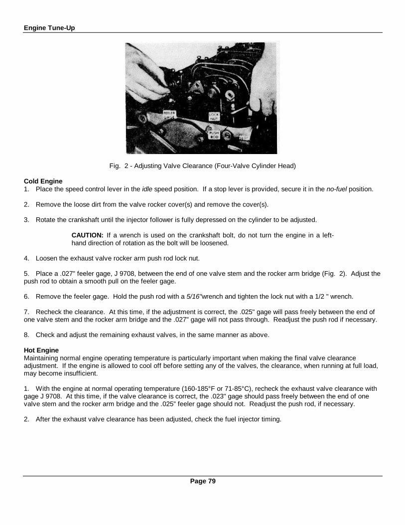
Engine Tune-Up
Fig. 2 - Adjusting Valve Clearance (Four-Valve Cylinder Head)
Cold Engine1. Place the speed control lever in the idle speed position. If a stop lever is provided, secure it in the no-fuel position.
2. Remove the loose dirt from the valve rocker cover(s) and remove the cover(s).
3. Rotate the crankshaft until the injector follower is fully depressed on the cylinder to be adjusted.
CAUTION: If a wrench is used on the crankshaft bolt, do not turn the engine in a left-hand direction of rotation as the bolt will be loosened.
4. Loosen the exhaust valve rocker arm push rod lock nut.
5. Place a .027" feeler gage, J 9708, between the end of one valve stem and the rocker arm bridge (Fig. 2). Adjust thepush rod to obtain a smooth pull on the feeler gage.
6. Remove the feeler gage. Hold the push rod with a 5/16"wrench and tighten the lock nut with a 1/2 " wrench.
7. Recheck the clearance. At this time, if the adjustment is correct, the .025" gage will pass freely between the end ofone valve stem and the rocker arm bridge and the .027" gage will not pass through. Readjust the push rod if necessary.
8. Check and adjust the remaining exhaust valves, in the same manner as above.
Hot EngineMaintaining normal engine operating temperature is particularly important when making the final valve clearanceadjustment. If the engine is allowed to cool off before setting any of the valves, the clearance, when running at full load,may become insufficient.
1. With the engine at normal operating temperature (160-185°F or 71-85°C), recheck the exhaust valve clearance withgage J 9708. At this time, if the valve clearance is correct, the .023" gage should pass freely between the end of onevalve stem and the rocker arm bridge and the .025" feeler gage should not. Readjust the push rod, if necessary.
2. After the exhaust valve clearance has been adjusted, check the fuel injector timing.
Page 79

Engine Tune-Up
TIMING FUEL INJECTOR
Timing ToolInjector Dimension Number
*35 1.508 J 890935 1.484 J 124240 1.484 J 124245 1.484 J 1242
S40 1.460 J 1853S45 1.460 J 1853S50 1.460 J 1853L40 1.460 J 1853N40 1.460 J 1853N45 1.460 J 1853N50 1.460 J 1853
*Reefer Car
To time a fuel injector properly, the injector follower must be adjusted to a definite height in relation to theinjector body. All of the injectors can be timed, in firing order sequence, during one full revolution of the crankshaft.
Time Fuel InjectorAfter the exhaust valve clearance has been adjusted, time the fuel injector as follows:
1. Place the speed control lever in the idle speed position. If a stop lever is provided, secure it in the no-fuel position.2. Rotate the crankshaft, manually or with the starting motor, until the exhaust valves are fully depressed on theparticular cylinder to be timed.
CAUTION: If a wrench is used on the crankshaft bolt at the front of the engine, do notturn the crankshaft in a left-hand direction of rotation or the bolt will be loosened.
Fig. 3 - Timing Fuel Injector
3. Place the small end of the injector timing gage (see table for correct timing gage) in the hole provided in the top ofthe injector body, with the flat of the gage toward the injector follower as shown in Fig. 3.4. Loosen the push rod lock nut.5. Turn the push rod and adjust the injector rocker arm until the extended part of the gage will just passover the top of the injector follower.6. Hold the push rod and tighten the lock nut. Check the adjustment and readjust, if necessary.7. Time the remaining injectors as outlined above.8. If no further engine tune-up is required, use a new gasket(s) and install the valve rocker cover(s).
Page 80

Engine Tune-Up
LIMITING SPEED MECHANICAL GOVERNOR AND INJECTOR RACKCONTROL ADJUSTMENT
IN-LINE ENGINES
The double-weight limiting speed governor is mounted on the rear end plate of the engine and is driven by a gear thatextends through the end plate and meshes with either the camshaft gear or the balance shaft gear, depending upon theengine model.
After adjusting the exhaust valves and tithing the fuel injectors, adjust the governor and position the injector rack controllevers.
NOTE: Before proceeding with the governor and injector rack adjustments, disconnectany supplementary governing device. After the adjustments are completed, re-connectand adjust the supplementary governing device.
Adjust Governor GapWith the engine stopped and at operating temperature, adjust the governor gap as follows:
1. Remove the high-speed spring retainer cover.2. Back out the buffer screw (Fig. 8) until it extends approximately 5/8" from the lock nut.3. Start the engine and adjust the idle speed screw (Fig. 7) to obtain the desired engine idle speed. Hold the screw andtighten the lock nut to hold the adjustment.
NOTE: The recommended idle speed for non-EPA certified engines is 500-600 rpm, butmay vary with special engine applications.
4. Stop the engine, clean and remove the governor cover and the valve rocker cover. Discard the gaskets.5. Start and run the engine, between 800 and 1000 rpm by manual operation of the injector control tube lever.
CAUTION: Do not overspeed the engine.
6. Check the gap between the low-speed spring cap and the high-speed spring plunger with a .0015 " feeler gage. If thegap setting is incorrect, reset the gap adjusting screw (Fig. 1). If the setting is correct, the .0015" movement can beseen by placing a few drops of oil into the governor gap and pressing a screw driver against the gap adjusting screw.Movement of the cap toward the plunger will force the oil from the gap in the form of a small bead.
Fig. 1 Adjusting Governor GapFig. 2 Positioning the Rear Injector Rack
Control Lever
Page 81

Engine Tune-Up
7. Hold the gap adjusting screw and tighten the lock nut.8. Recheck the gap and readjust if necessary.9. Stop the engine and, using a new gasket, install the governor cover. The governor cover should be placed on thehousing with the pin of the speed control lever projecting into the slot of the differential lever.10. Install screws and lock washers finger tight. Pull the cover away from the engine and tighten the screws. This stepwill properly locate the cover on the governor housing.
Position Injector Rack Control LeversThe position of the injector racks must be correctly set in relation to the governor. Their position determines the amountof fuel injected into each cylinder and ensures equal distribution of the load. Properly positioned injector rack controllevers with the engine at full-load will result in the following:
1. Speed control lever at the full-fuel position.2. Governor low-speed gap closed.3. High-speed spring plunger on the seat in the governor control housing.4. Injector racks in the full-fuel position.
Adjust the rear injector rack control lever first to establish a guide for adjusting the remaining injector rack control levers.
1. Disconnect any linkage attached to the speed control lever.2. Turn the idle speed adjusting screw until 1/2"of the threads (12-14 threads) project from the lock nut, when the nut isagainst the high-speed plunger.
CAUTION: A false fuel rack setting may result if the idle speed adjusting screw is notbacked out as noted above.
NOTE: This adjustment lowers the tension of the low-speed spring so it can be easilycompressed. This permits closing the low speed gap without bending the fuel rods orcausing the yield mechanism springs to yield or stretch.
3. Back out the buffer screw approximately 5/8", if it has not already been done.4. Loosen all of the inner and outer injector rack control lever adjusting screws (Fig. 2). Be sure all of the levers arefree on the injector control tube.
5. Move the speed control lever to the maximum speed position. Turn the inner adjusting screw down on the rearinjector rack control lever until a step-up in effort is noted. This will place the rear injector rack in the full-fuel position.Turn down the outer adjusting screw until it bottoms lightly on the injector control tube. Then alternately tighten both theinner and outer adjusting screws. This should result in placing the governor linkage and control tube assembly in thesame positions that they will attain while the engine is running at full-load.
Fig. 3 - Checking Rotating Movement ofInjector Control Rack Fig. 4 - Checking Injector Rack "Spring'
Page 82

Engine Tune-Up
6. To be sure of the proper rack adjustment, hold the speed control lever in the full-fuel position and press down on theinjector rack with a screw driver or finger tip and note "rotating" movement of the injector control rack (Fig. 3) when thespeed control lever is in the maximum speed position. Hold the speed control lever in the maximum speed position and,using a screw driver, press downward on the injector control rack. The rack should tilt downward (Fig. 4) and whenthe pressure of the screw driver is released, the control rack should "spring" back upward.
If the rack does not return to its original position, it is too loose. To correct this condition, back off the outer adjustingscrew slightly and tighten the inner adjusting screw slightly.
The setting is too tight if, when moving the speed control lever from the no-speed to the maximum speed position, theinjector rack becomes tight before the speed control lever reaches the end of its travel (as determined by the stop underthe governor cover). This will result in a step-up in effort required to move the speed control lever to the end of its travel.To correct this condition, back off the inner adjusting screw slightly and tighten the outer adjusting screw slightly.
NOTE: Overtightening of the injector rack control lever adjusting screws duringinstallation or adjustment can result in damage to the injector control tube. Therecommended torque of the adjusting screws is 24-36 in-lbs (3-4 Nm).
IMPORTANT: The above step should result in placing the governor linkage and controltube assembly in the same position that they will attain while the engine is running at fullload.
7. To adjust the remaining injector rack control levers, remove the clevis pin from the fuel rod and the injector controltube lever, hold the injector control racks in the full-fuel position by means of the lever on the end of the control tube.Turn down the inner adjusting screw on the injector rack control lever of the adjacent injector until the injector rack hasmoved into the full-fuel position and the inner adjusting screw is bottomed on the injector control tube. Turn the outeradjusting screw down until it bottoms lightly on the injector control tube. Then alternately tighten both the inner and outeradjusting screws.
8. Recheck the rear injector rack to be sure that it has remained snug on the ball end of the injector rack control leverwhile adjusting the adjacent injector. If the rack of the rear injector has become loose, back off, the inner adjusting screwslightly on the adjacent injector rack control lever. Tighten the outer adjusting screw. When the settings are correct, theracks of both injectors must be snug on the ball end of their respective rack control levers.
Fig. 5 - Adjusting Maximum No-Load EngineSpeed (Type A) Fig. 6 - Governor Spring Assemblies
Page 83

Engine Tune-Up9. Position the remaining injector rack control levers as outlined in Steps 6 and 7.10. Connect the fuel rod to the injector control tube lever.11. Turn the idle speed adjusting screw in until it projects 3/16" from the lock nut to permit starting the engine. Tightenthe lock nut.12. Use a new gasket and replace the valve rocker cover.
Adjust Maximum No-Load Engine SpeedAll governors are properly adjusted before leaving the factory. However, if the governor has been reconditioned orreplaced, and to ensure the engine speed will not exceed the recommended no-load speed as given on the engineoption plate, set the maximum no-loadspeed as follows:
TYPE A GOVERNOR SPRINGS (Fig. 6):1. Loosen the lock nut (Fig. 5) and back off the high-speed spring retainer approximately five turns.2. With the engine at operating temperature and no-load on the engine, place the speed control lever in the full-fuelposition. Turn the high-speed spring retainer IN until the engine is operating at the recommended no-load speed.The best method of determining the engine speed is with an accurate tachometer.3. Hold the high-speed spring retainer and tighten the lock nut.
TYPE B GOVERNOR SPRINGS (Fig. 6):1. Start the engine and after it reaches normal operating temperature, remove the load from the engine.2. Place the speed control lever in the maximum speed position and note the engine speed.3. Stop the engine and, if necessary, adjust the no-load speed as follows:
a. Remove the high-speed spring retainer, high-speed spring and plunger.
CAUTION: To prevent the low-speed spring and cap from dropping into the governor, becareful not to jar the assembly while it is being removed.
b. Remove the high-speed spring from the high-speed spring plunger and add or remove shims (Fig. 6) as requiredto establish the desired engine no-load speed.
NOTE: For each .010" shim added, the engine speed will be increased approximately 10rpm.
c. Install the high-speed spring on the plunger and install the spring assembly in the governor housing. Install thespring retainer in the governor housing and tighten it securely.
d. Start the engine and recheck the engine no-load speed. Repeat the procedure as necessary to establish the no-load speed.
Adjust Idle SpeedWith the maximum no-load speed properly adjusted, adjust the idle speed as follows:1. With the engine running at normal operating temperature and with the buffer screw backed out to avoid contact withthe differential lever, turn the idle speed adjusting screw (Fig. 7) until the engine is operating at approximately 15 rpmbelow the recommended idle speed.
NOTE: The recommended idle speed for non-EPA certified engines is 500-600 rpm, butmay vary with special engine applications.
2. Hold the idle speed adjusting screw and tighten the lock nut.
Fig. Adjusting Engine Idle Speed
Page 84Engine Tune-Up
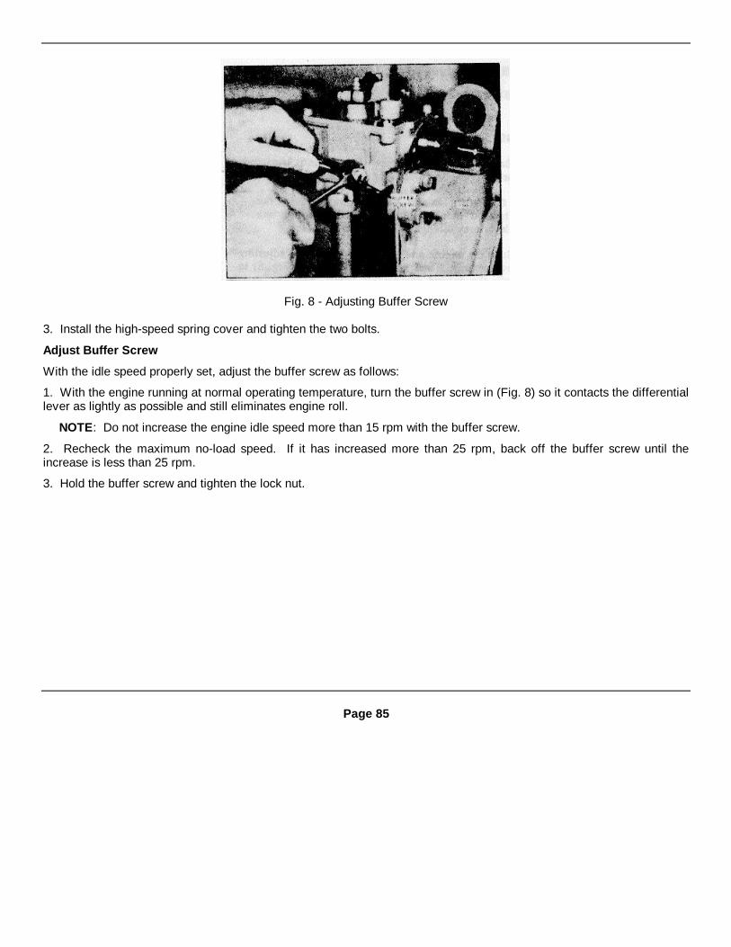
Fig. 8 - Adjusting Buffer Screw
3. Install the high-speed spring cover and tighten the two bolts.
Adjust Buffer Screw
With the idle speed properly set, adjust the buffer screw as follows:
1. With the engine running at normal operating temperature, turn the buffer screw in (Fig. 8) so it contacts the differentiallever as lightly as possible and still eliminates engine roll.
NOTE: Do not increase the engine idle speed more than 15 rpm with the buffer screw.
2. Recheck the maximum no-load speed. If it has increased more than 25 rpm, back off the buffer screw until theincrease is less than 25 rpm.
3. Hold the buffer screw and tighten the lock nut.
Page 85
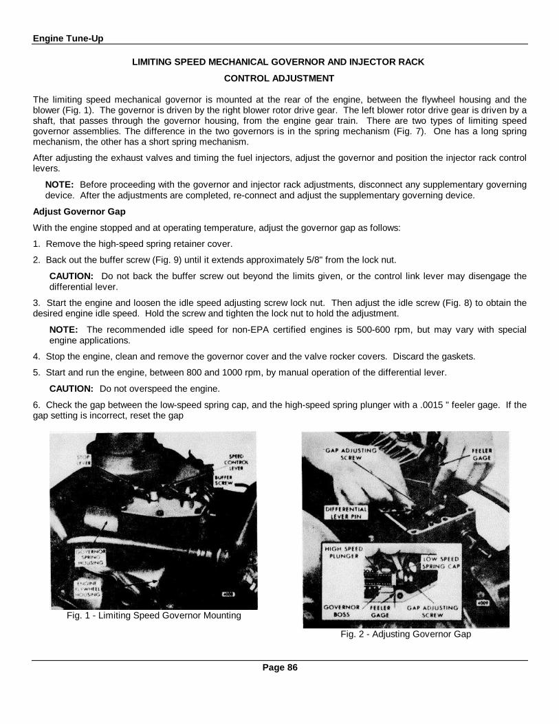
Engine Tune-Up
LIMITING SPEED MECHANICAL GOVERNOR AND INJECTOR RACK
CONTROL ADJUSTMENT
The limiting speed mechanical governor is mounted at the rear of the engine, between the flywheel housing and theblower (Fig. 1). The governor is driven by the right blower rotor drive gear. The left blower rotor drive gear is driven by ashaft, that passes through the governor housing, from the engine gear train. There are two types of limiting speedgovernor assemblies. The difference in the two governors is in the spring mechanism (Fig. 7). One has a long springmechanism, the other has a short spring mechanism.
After adjusting the exhaust valves and timing the fuel injectors, adjust the governor and position the injector rack controllevers.
NOTE: Before proceeding with the governor and injector rack adjustments, disconnect any supplementary governingdevice. After the adjustments are completed, re-connect and adjust the supplementary governing device.
Adjust Governor Gap
With the engine stopped and at operating temperature, adjust the governor gap as follows:
1. Remove the high-speed spring retainer cover.
2. Back out the buffer screw (Fig. 9) until it extends approximately 5/8" from the lock nut.
CAUTION: Do not back the buffer screw out beyond the limits given, or the control link lever may disengage thedifferential lever.
3. Start the engine and loosen the idle speed adjusting screw lock nut. Then adjust the idle screw (Fig. 8) to obtain thedesired engine idle speed. Hold the screw and tighten the lock nut to hold the adjustment.
NOTE: The recommended idle speed for non-EPA certified engines is 500-600 rpm, but may vary with specialengine applications.
4. Stop the engine, clean and remove the governor cover and the valve rocker covers. Discard the gaskets.
5. Start and run the engine, between 800 and 1000 rpm, by manual operation of the differential lever.
CAUTION: Do not overspeed the engine.
6. Check the gap between the low-speed spring cap, and the high-speed spring plunger with a .0015 " feeler gage. If thegap setting is incorrect, reset the gap
Fig. 1 - Limiting Speed Governor Mounting
Fig. 2 - Adjusting Governor Gap
Page 86

Engine Tune-Up
adjusting screw (Fig. 2). If the setting is correct, the.0015" movement can be seen by placing a few drops ofoil into the governor gap and pressing a screw driveragainst the gap adjusting screw. Movement of the captoward the plunger will force the oil from the gap in theform of a small bead.
7. Hold the gap adjusting screw and tighten the locknut.
8. Recheck the gap and readjust if necessary.
9. Stop the engine and, using a new gasket, install thegovernor cover.
Position Injector Rack Control Levers
The position of the injector racks must be correctly set inrelation to the governor. Their position determines theamount of fuel injected into each cylinder and ensuresequal distribution of the load. Properly positionedinjector rack control levers with the engine at full-loadwill result in the following:
1. Speed control lever at the maximum speed position.
2. Governor low-speed gap closed.
3. High-speed spring plunger on the seat in thegovernor control housing.
4. Injector fuel control racks in the full-fuel position.
Fig. 3 - Positioning No. 3L Injector Rack
Control Lever
The letters R or L indicate the injector location in theright or left cylinder bank, viewed from the rear of the
engine. Cylinders are numbered starting at the front ofthe engine on each cylinder bank. Adjust the No. 3Linjector rack control lever first to establish a guide foradjusting the remaining injector rack control levers.
1. Disconnect any linkage attached to the speed controllever.
2. Turn the idle speed adjusting screw until 1/2" of thethreads (12-14 threads) project from the lock nut whenthe nut is against the high-speed plunger.
CAUTION: A false fuel rack setting may result ifthe idle speed adjusting screw is not backed out asnoted above.
NOTE: This adjustment lowers the tension of thelow-speed spring so it can be easily compressed.This permits closing the low speed gap withoutbending the fuel rods or causing the yieldmechanism springs to yield or stretch.
3. Back out the buffer screw approximately 5/8", if ithas not already been done.
4. Remove the clevis pin from the fuel rod and the rightcylinder bank injector control tube lever.
5. Loosen all of the inner and outer injector rack controllever adjusting screws on both injector control tubes. Besure all of the injector rack control levers are free on theinjector control tubes.
6. Move the speed control lever to the maximum speedposition; hold it in that position with light finger pressure.Turn the inner adjusting screw on the
Fig. 4 · Checking Rotating Movement ofInjector Control Rack
Page 87
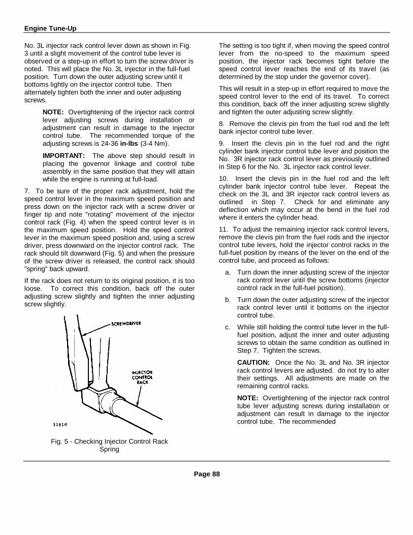
Engine Tune-Up
No. 3L injector rack control lever down as shown in Fig.3 until a slight movement of the control tube lever isobserved or a step-up in effort to turn the screw driver isnoted. This will place the No. 3L injector in the full-fuelposition. Turn down the outer adjusting screw until itbottoms lightly on the injector control tube. Thenalternately tighten both the inner and outer adjustingscrews.
NOTE: Overtightening of the injector rack controllever adjusting screws during installation oradjustment can result in damage to the injectorcontrol tube. The recommended torque of theadjusting screws is 24-36 in-lbs (3-4 Nm).
IMPORTANT: The above step should result inplacing the governor linkage and control tubeassembly in the same position that they will attainwhile the engine is running at full-load.
7. To be sure of the proper rack adjustment, hold thespeed control lever in the maximum speed position andpress down on the injector rack with a screw driver orfinger tip and note "rotating" movement of the injectorcontrol rack (Fig. 4) when the speed control lever is inthe maximum speed position. Hold the speed controllever in the maximum speed position and, using a screwdriver, press downward on the injector control rack. Therack should tilt downward (Fig. 5) and when the pressureof the screw driver is released, the control rack should"spring" back upward.
If the rack does not return to its original position, it is tooloose. To correct this condition, back off the outeradjusting screw slightly and tighten the inner adjustingscrew slightly.
Fig. 5 - Checking Injector Control RackSpring
The setting is too tight if, when moving the speed controllever from the no-speed to the maximum speedposition, the injector rack becomes tight before thespeed control lever reaches the end of its travel (asdetermined by the stop under the governor cover).
This will result in a step-up in effort required to move thespeed control lever to the end of its travel. To correctthis condition, back off the inner adjusting screw slightlyand tighten the outer adjusting screw slightly.
8. Remove the clevis pin from the fuel rod and the leftbank injector control tube lever.
9. Insert the clevis pin in the fuel rod and the rightcylinder bank injector control tube lever and position theNo. 3R injector rack control lever as previously outlinedin Step 6 for the No. 3L injector rack control lever.
10. Insert the clevis pin in the fuel rod and the leftcylinder bank injector control tube lever. Repeat thecheck on the 3L and 3R injector rack control levers asoutlined in Step 7. Check for and eliminate anydeflection which may occur at the bend in the fuel rodwhere it enters the cylinder head.
11. To adjust the remaining injector rack control levers,remove the clevis pin from the fuel rods and the injectorcontrol tube levers, hold the injector control racks in thefull-fuel position by means of the lever on the end of thecontrol tube, and proceed as follows:
a. Turn down the inner adjusting screw of the injectorrack control lever until the screw bottoms (injectorcontrol rack in the full-fuel position).
b. Turn down the outer adjusting screw of the injectorrack control lever until it bottoms on the injectorcontrol tube.
c. While still holding the control tube lever in the full-fuel position, adjust the inner and outer adjustingscrews to obtain the same condition as outlined inStep 7. Tighten the screws.
CAUTION: Once the No. 3L and No. 3R injectorrack control levers are adjusted. do not try to altertheir settings. All adjustments are made on theremaining control racks.
NOTE: Overtightening of the injector rack controltube lever adjusting screws during installation oradjustment can result in damage to the injectorcontrol tube. The recommended
Page 88
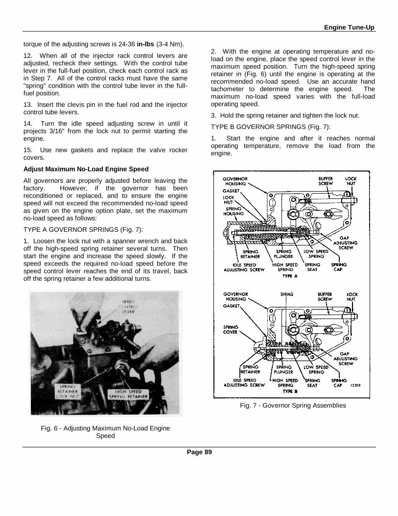
Engine Tune-Up
torque of the adjusting screws is 24-36 in-lbs (3-4 Nm).
12. When all of the injector rack control levers areadjusted, recheck their settings. With the control tubelever in the full-fuel position, check each control rack asin Step 7. All of the control racks must have the same"spring" condition with the control tube lever in the full-fuel position.
13. Insert the clevis pin in the fuel rod and the injectorcontrol tube levers.
14. Turn the idle speed adjusting screw in until itprojects 3/16" from the lock nut to permit starting theengine.
15. Use new gaskets and replace the valve rockercovers.
Adjust Maximum No-Load Engine Speed
All governors are properly adjusted before leaving thefactory. However, if the governor has beenreconditioned or replaced, and to ensure the enginespeed will not exceed the recommended no-load speedas given on the engine option plate, set the maximumno-load speed as follows:
TYPE A GOVERNOR SPRINGS (Fig. 7):
1. Loosen the lock nut with a spanner wrench and backoff the high-speed spring retainer several turns. Thenstart the engine and increase the speed slowly. If thespeed exceeds the required no-load speed before thespeed control lever reaches the end of its travel, backoff the spring retainer a few additional turns.
Fig. 6 - Adjusting Maximum No-Load EngineSpeed
2. With the engine at operating temperature and no-load on the engine, place the speed control lever in themaximum speed position. Turn the high-speed springretainer in (Fig. 6) until the engine is operating at therecommended no-load speed. Use an accurate handtachometer to determine the engine speed. Themaximum no-load speed varies with the full-loadoperating speed.
3. Hold the spring retainer and tighten the lock nut.
TYPE B GOVERNOR SPRINGS (Fig. 7):
1. Start the engine and after it reaches normaloperating temperature, remove the load from theengine.
Fig. 7 - Governor Spring Assemblies
Page 89

Engine Tune-Up
3. Stop the engine and, if necessary, adjust the no-loadspeed as follows:
a. Remove the high-speed spring retainer with tool J5895 and withdraw the high-speed spring andplunger assembly.
CAUTION: To prevent the low-speed spring andcap from dropping into the governor, be carefulnot to jar the assembly while it is being removed.
b. Remove the high-speed spring from the high-speed spring plunger and add or remove shims asrequired to establish the desired engine no-loadspeed.
NOTE: For each .010"in shims added, theengine speed will be increased approximately 10rpm.
c. Install the high-speed spring on the plunger andinstall the spring assembly in the governorhousing. Install the spring retainer in the governorhousing and tighten it securely. The maximumno-load speed varies with the full-load operatingspeed desired.
d. Start the engine and recheck the no-load speed.Repeat the procedure as necessary to establishthe no-load speed required.
Adjust Idle Speed
With the maximum no-load speed properly adjusted,adjust the idle speed as follows:
1. With the engine running at normal operatingtemperature and with the buffer screw backed out to
Fig. 8 - Adjusting Engine Idle Speed
avoid contact with the differential lever, turn the idlespeed adjusting screw (Fig. 8) until the engine isoperating at approximately 15 rpm below therecommended idle speed.
NOTE: The recommended idle speed for non-EPA certified engines is 500-600 rpm, but mayvary with special engine applications.
If the engine has a tendency to stall during deceleration,install a new buffer screw. The current buffer screwuses a heavier spring and restricts the travel of thedifferential lever to the off (no-fuel) position.
2. Hold the idle screw and tighten the lock nut.
3. Install the high-speed spring retainer cover andtighten the two bolts.
Adjust Buffer Screw
With the idle speed properly set, adjust the buffer screwas follows:
1. With the engine running at normal operatingtemperature, turn the buffer screw in (Fig. 9) so itcontacts the differential lever as lightly as possible andstill eliminates engine roll.
NOTE: Do not increase the engine idle speedmore than 15 rpm with the buffer screw.
2. Recheck the maximum no-load speed. If it hasincreased more than 25 rpm, back off the buffer screwuntil the increase is less than 25 rpm.
3. Hold the buffer screw and tighten the lock nut.
Fig. 9 - Adjusting Buffer Screw
Page 90

Engine Tune-Up
VARIABLE SPEED MECHANICAL GOVERNOR (OPEN LINKAGE) AND
INJECTOR RACK CONTROL ADJUSTMENT
IN-LINE ENGINES
After adjusting the exhaust valves and timing the fuelinjectors, adjust the governor (Fig. I) and the injectorrack control levers.
Preliminary Governor Adjustments
1. Clean the governor linkage and lubricate the balljoints and bearing surfaces with clean engine oil.
2. Back out the buffer screw until it projects 9/ 16" fromthe boss on the control housing.
Fig. 1 - Variable Speed Open Linkage GovernorMounted on Engine
3. Back out the booster spring eye bolt until it is flushwith the outer lock nut.
Adjust Variable Speed Spring Tension
1. Adjust the variable speed spring eye bolt until 1/8" ofthe threads project from the outer lock nut .(Fig. 2).
2. Tighten both lock nuts to retain the adjustment.
NOTE: This setting of the eye bolt will produceapproximately 7% droop in engine speed from no-load to full-load.
Position Injector Rack Control Lovers
The position of the injector control racks must becorrectly set in relation to the governor. Their position
Fig. 2 - Adjusting Governor Spring Eye Bolt
Page 91

Engine Tune-Up
determines the amount of fuel injected into eachcylinder and ensures equal distribution of the load.Adjust the rear injector rack control lever first toestablish a guide for adjusting the remaining levers.
1. Clean and remove the valve rocker cover. Discardthe gasket.
2. Disconnect the fuel rod at the stop lever.
3. Loosen all of the inner and outer injector rack controllever adjusting screws. Be sure all of the injector rackcontrol levers are free on the injector control tube.
4. Move the speed control lever to the maximum speedposition.
5. Adjust the rear cylinder injector rack control leveradjusting screws (Fig. 3) until both screws are equal inheight and tight on the injector control tube.
6. Move the rear injector control rack into the full-fuelposition and note the clearance between the fuel rodand the cylinder head bolt. The clearance should be1/32 " or more. If necessary, readjust the injector rackadjusting screws until a clearance of at least 1/32" to1/16" exists. Tighten the adjustment screws.
Fig. 3 - Adjusting Injector Rack Control LeverAdjusting Screws
7. Loosen the nut which locks the ball joint on the fuelrod. Hold the fuel rod in the full-fuel position and adjustthe ball joint until it is aligned and will slide on the ballstud on the stop lever (Fig. 4). Position the shutdowncable clip and tighten the fuel rod lock nut to retain theadjustment.
8. Check the adjustment by pushing the fuel rod towardthe engine and make sure the injector control rack is inthe full-fuel position. If necessary, readjust the fuel rod.
9. Manually hold the rear injector rack in the full-fuelposition, with the lever on the injector control tube, andturn the inner adjusting screw of the adjacent injectorrack control lever down until the injector rack moves intothe full-fuel position. Turn the outer adjusting screwdown until it bottoms lightly on the injector control tube.Then alternately tighten both the inner and outeradjusting screws.
NOTE: Overtightening of the injector rack controllever adjusting screws during installation oradjustment can result in damage to the injectorcontrol tube. The recommended torque of theadjusting screws is 24-36 in-lbs (3-4 Nm).
10. Recheck the rear injector rack to be sure that it hasremained snug on the ball end of the rack control leverwhile adjusting the adjacent injector rack. If the rack ofthe rear injector has become loose, back off the inneradjusting screw slightly on the adjacent injector rackcontrol lever and tighten the outer adjusting screw.When the settings are correct, the racks of both injectorsmust be snug on the ball end of their respective controllevers.
Fig. 4 - Adjusting Fuel Rod Length
Page 92

Engine Tune-Up
11. Position the remaining injector rack control leversas outlined in Steps 9 and 10.
Adjust Maximum No-Load Speed
1. With the engine running, move the speed controllever to the maximum speed position. Use an accuratetachometer to determine the no-load speed of theengine.
NOTE: Do not overspeed the engine.
2. Loosen the lock nut and adjust the maximum speedadjusting screw (Fig. 5) until the required no-load speedis obtained.
3. Hold the adjusting screw and tighten the lock nut.
Adjust Engine Idle Speed
1. Make sure the stop lever is in the run position andplace the speed control lever in the idle position.
2. With the engine running at normal operatingtemperature, loosen the lock nut and turn the idle speedadjusting screw (Fig. 6) until the engine idles at therecommended speed. The recommended idle speed
Fig. 5 - Adjusting Maximum No-Load EngineSpeed
is 500 rpm. However, the idle speed may vary withspecial engine applications.3. Hold the idle speed adjusting screw and tighten thelock nut.
Adjust Buffer Screw
1. With the engine running at idle speed, turn the bufferscrew in (Fig. 7) so that it contacts the stop lever aslightly as possible and still eliminates engine roll.
NOTE: Do not raise the engine idle speed morethan 20 rpm with the buffer screw. Check themaximum no-load speed to make sure it has notincreased over 25 rpm by the buffer screw setting.
Adjust Governor Booster Spring
The governor booster spring is used on some engines toreduce the force necessary to move the speed controllever from the idle speed position to the maximumspeed position. Adjust the booster spring as follows:
1. Move the speed control lever to the idle speedposition.
2. Reduce the tension on the booster spring, if not
Fig. 6 - Adjusting Idle Speed
Page 93

Engine Tune-Up
Fig. 7 - Adjusting Buffer Screw
previously performed, to the minimum by backing offthe outer lock nut (Fig. 8) until the end of the boosterspring eye bolt is flush with the end of the nut.
3. Adjust the eye bolt in the slot in the bracket so thatan imaginary line through the booster spring will alignwith an imaginary center line through the speed controlshaft. Secure the lock nuts on the eye bolt to retain theadjustment.
4. Move the speed control lever to the maximum speedposition and note the force required. To reduce theforce, back off the inner lock nut and tighten the outerlock nut to increase the tension on the booster spring.
NOTE: Before tightening the lock nuts, repositionthe booster spring as in Step 3.
The setting is correct when the speed control lever canbe moved from the idle speed position to the maximumspeed position with a constant force, while the engine isrunning, and when released it will return to the idlespeed position.
Fig. 8 - Adjusting Booster Spring
Adjust Engine Speed Droop
The adjustment of the spring tension as outlined underAdjust Variable Speed Spring Tension will result inapproximately 7% droop from the maximum no-loadspeed to the full-load speed. This is the optimum droopsetting for most applications. However, the droop maybe changed as necessary for a particular engineapplication.
1. Lower the speed droop by increasing the springtension.
2. Raise the speed droop by decreasing the springtension.
NOTE: A change in the variable speed springtension will change the maximum no-load speedand the engine idle speed which must also bereadjusted.
Page 94

Engine Tune-UpVARIABLE SPEED MECHANICAL GOVERNOR (ENCLOSED LINKAGE) AND
INJECTOR RACK CONTROL ADJUSTMENT
IN-LINE ENGINES
The single-weight variable speed governor is mounted on the rear end plate of the engine and is driven by a gear thatextends through the end plate and meshes with either the camshaft gear or the balance shaft gear, depending upon theengine model.
After adjusting the exhaust valves and timing the fuel injectors, adjust the governor and position the injector rack controllevers.
NOTE: Before proceeding with the governor and injector rack adjustments, disconnect any supplementarygoverning device. After the adjustments are completed, reconnect and adjust the supplementary governingdevice.
Adjust Governor Gap
With the engine stopped and at operating temperature, adjust the governor gap as follows:
1. Disconnect any linkage attached to the governor levers.
2. Back out the buffer screw until it extends approximately 5/8" from the lock nut.
3. Clean and remove the governor cover and valve rocker cover. Discard the gaskets.
4. Place the speed control lever (Fig. 1) in the maximum speed position.
5. Insert a .006" feeler gage between the spring plunger and the plunger guide as shown in Fig. 1. If required,loosen the lock nut and turn the gap adjusting screw in or out until a slight drag is noted on the feeler gage.
6. Hold the adjusting screw and tighten the lock nut. Check the gap and readjust if necessary.
7. Use a new gasket and install the governor cover as follows:
a. Place the cover on the governor housing, with the
Fig. 1 - Checking Governor Gap Fig. 2 - Positioning the Rear Injector Rack Control Lever
Page 95
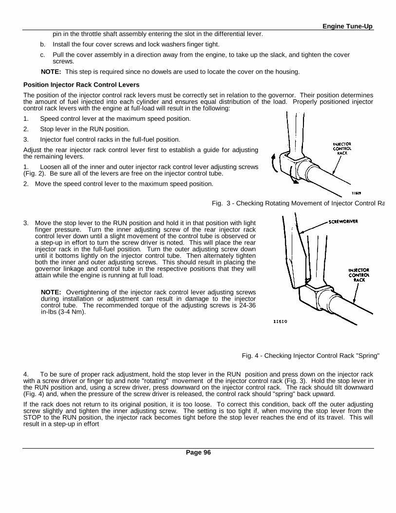
Engine Tune-Uppin in the throttle shaft assembly entering the slot in the differential lever.
b. Install the four cover screws and lock washers finger tight.
c. Pull the cover assembly in a direction away from the engine, to take up the slack, and tighten the cover screws.
NOTE: This step is required since no dowels are used to locate the cover on the housing.
Position Injector Rack Control Levers
The position of the injector control rack levers must be correctly set in relation to the governor. Their position determinesthe amount of fuel injected into each cylinder and ensures equal distribution of the load. Properly positioned injectorcontrol rack levers with the engine at full-load will result in the following:
1. Speed control lever at the maximum speed position.
2. Stop lever in the RUN position.
3. Injector fuel control racks in the full-fuel position.
Adjust the rear injector rack control lever first to establish a guide for adjustingthe remaining levers.
1. Loosen all of the inner and outer injector rack control lever adjusting screws(Fig. 2). Be sure all of the levers are free on the injector control tube.
2. Move the speed control lever to the maximum speed position.
3. Move the stop lever to the RUN position and hold it in that position with lightfinger pressure. Turn the inner adjusting screw of the rear injector rackcontrol lever down until a slight movement of the control tube is observed ora step-up in effort to turn the screw driver is noted. This will place the rearinjector rack in the full-fuel position. Turn the outer adjusting screw downuntil it bottoms lightly on the injector control tube. Then alternately tightenboth the inner and outer adjusting screws. This should result in placing thegovernor linkage and control tube in the respective positions that they willattain while the engine is running at full load.
NOTE: Overtightening of the injector rack control lever adjusting screwsduring installation or adjustment can result in damage to the injectorcontrol tube. The recommended torque of the adjusting screws is 24-36in-lbs (3-4 Nm).
4. To be sure of proper rack adjustment, hold the stop lever in the RUN position and press down on the injector rackwith a screw driver or finger tip and note "rotating" movement of the injector control rack (Fig. 3). Hold the stop lever inthe RUN position and, using a screw driver, press downward on the injector control rack. The rack should tilt downward(Fig. 4) and, when the pressure of the screw driver is released, the control rack should "spring" back upward.
If the rack does not return to its original position, it is too loose. To correct this condition, back off the outer adjustingscrew slightly and tighten the inner adjusting screw. The setting is too tight if, when moving the stop lever from theSTOP to the RUN position, the injector rack becomes tight before the stop lever reaches the end of its travel. This willresult in a step-up in effort
Page 96
Fig. 3 - Checking Rotating Movement of Injector Control Rack.
Fig. 4 - Checking Injector Control Rack "Spring"
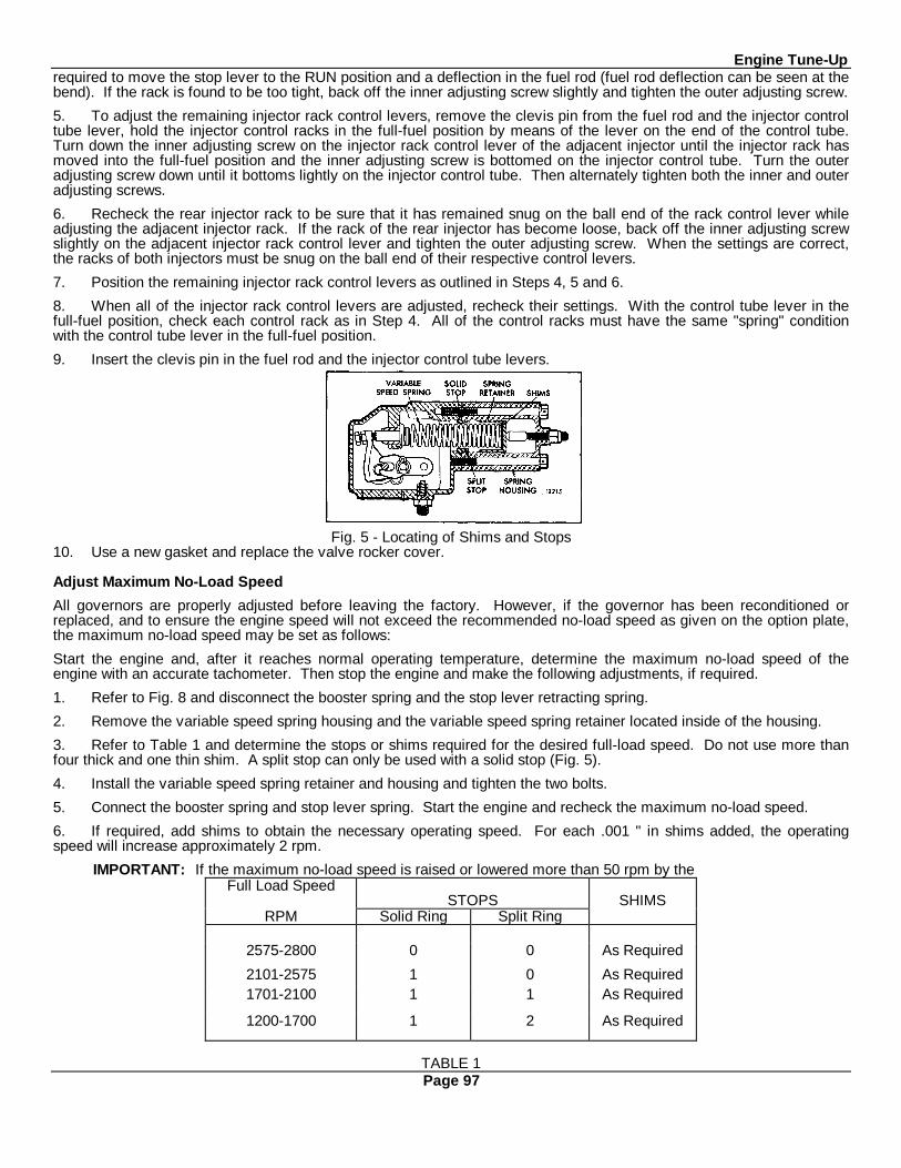
Engine Tune-Uprequired to move the stop lever to the RUN position and a deflection in the fuel rod (fuel rod deflection can be seen at thebend). If the rack is found to be too tight, back off the inner adjusting screw slightly and tighten the outer adjusting screw.
5. To adjust the remaining injector rack control levers, remove the clevis pin from the fuel rod and the injector controltube lever, hold the injector control racks in the full-fuel position by means of the lever on the end of the control tube.Turn down the inner adjusting screw on the injector rack control lever of the adjacent injector until the injector rack hasmoved into the full-fuel position and the inner adjusting screw is bottomed on the injector control tube. Turn the outeradjusting screw down until it bottoms lightly on the injector control tube. Then alternately tighten both the inner and outeradjusting screws.
6. Recheck the rear injector rack to be sure that it has remained snug on the ball end of the rack control lever whileadjusting the adjacent injector rack. If the rack of the rear injector has become loose, back off the inner adjusting screwslightly on the adjacent injector rack control lever and tighten the outer adjusting screw. When the settings are correct,the racks of both injectors must be snug on the ball end of their respective control levers.
7. Position the remaining injector rack control levers as outlined in Steps 4, 5 and 6.
8. When all of the injector rack control levers are adjusted, recheck their settings. With the control tube lever in thefull-fuel position, check each control rack as in Step 4. All of the control racks must have the same "spring" conditionwith the control tube lever in the full-fuel position.
9. Insert the clevis pin in the fuel rod and the injector control tube levers.
Fig. 5 - Locating of Shims and Stops10. Use a new gasket and replace the valve rocker cover.
Adjust Maximum No-Load Speed
All governors are properly adjusted before leaving the factory. However, if the governor has been reconditioned orreplaced, and to ensure the engine speed will not exceed the recommended no-load speed as given on the option plate,the maximum no-load speed may be set as follows:
Start the engine and, after it reaches normal operating temperature, determine the maximum no-load speed of theengine with an accurate tachometer. Then stop the engine and make the following adjustments, if required.
1. Refer to Fig. 8 and disconnect the booster spring and the stop lever retracting spring.
2. Remove the variable speed spring housing and the variable speed spring retainer located inside of the housing.
3. Refer to Table 1 and determine the stops or shims required for the desired full-load speed. Do not use more thanfour thick and one thin shim. A split stop can only be used with a solid stop (Fig. 5).
4. Install the variable speed spring retainer and housing and tighten the two bolts.
5. Connect the booster spring and stop lever spring. Start the engine and recheck the maximum no-load speed.
6. If required, add shims to obtain the necessary operating speed. For each .001 " in shims added, the operatingspeed will increase approximately 2 rpm.
IMPORTANT: If the maximum no-load speed is raised or lowered more than 50 rpm by theFull Load Speed
STOPS SHIMSRPM Solid Ring Split Ring
2575-2800 0 0 As Required
2101-2575 1 0 As Required1701-2100 1 1 As Required
1200-1700 1 2 As Required
TABLE 1Page 97
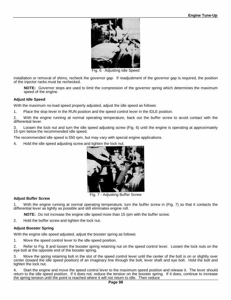
Engine Tune-Up
Fig. 6 · Adjusting Idle Speed
installation or removal of shims, recheck the governor gap. If readjustment of the governor gap is required, the positionof the injector racks must be rechecked.
NOTE: Governor stops are used to limit the compression of the governor spring which determines the maximumspeed of the engine.
Adjust Idle Speed
With the maximum no-load speed properly adjusted, adjust the idle speed as follows:
1. Place the stop lever in the RUN position and the speed control lever in the IDLE position.
2. With the engine running at normal operating temperature, back out the buffer screw to avoid contact with thedifferential lever.
3. Loosen the lock nut and turn the idle speed adjusting screw (Fig. 6) until the engine is operating at approximately15 rpm below the recommended idle speed.
The recommended idle speed is 550 rpm, but may vary with special engine applications.
4. Hold the idle speed adjusting screw and tighten the lock nut.
Fig. 7 - Adjusting Buffer ScrewAdjust Buffer Screw
1. With the engine running at normal operating temperature, turn the buffer screw in (Fig. 7) so that it contacts thedifferential lever as lightly as possible and still eliminates engine roll.
NOTE: Do not increase the engine idle speed more than 15 rpm with the buffer screw.
2. Hold the buffer screw and tighten the lock nut.
Adjust Booster Spring
With the engine idle speed adjusted, adjust the booster spring as follows:
1. Move the speed control lever to the idle speed position.
2. Refer to Fig. 8 and loosen the booster spring retaining nut on the speed control lever. Loosen the lock nuts on theeye bolt at the opposite end of the booster spring.
3. Move the spring retaining bolt in the slot of the speed control lever until the center of the bolt is on or slightly overcenter (toward the idle speed position) of an imaginary line through the bolt, lever shaft and eye bolt. Hold the bolt andtighten the lock nut.
4. Start the engine and move the speed control lever to the maximum speed position and release it. The lever shouldreturn to the idle speed position. If it does not, reduce the tension on the booster spring. If it does, continue to increasethe spring tension until the point is reached where it will not return to idle. Then reduce
Page 98
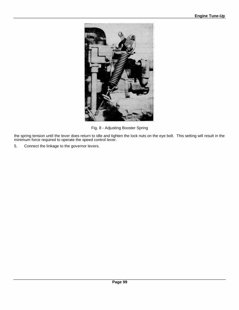
Engine Tune-Up
Fig. 8 - Adjusting Booster Spring
the spring tension until the lever does return to idle and tighten the lock nuts on the eye bolt. This setting will result in theminimum force required to operate the speed control lever.
5. Connect the linkage to the governor levers.
Page 99
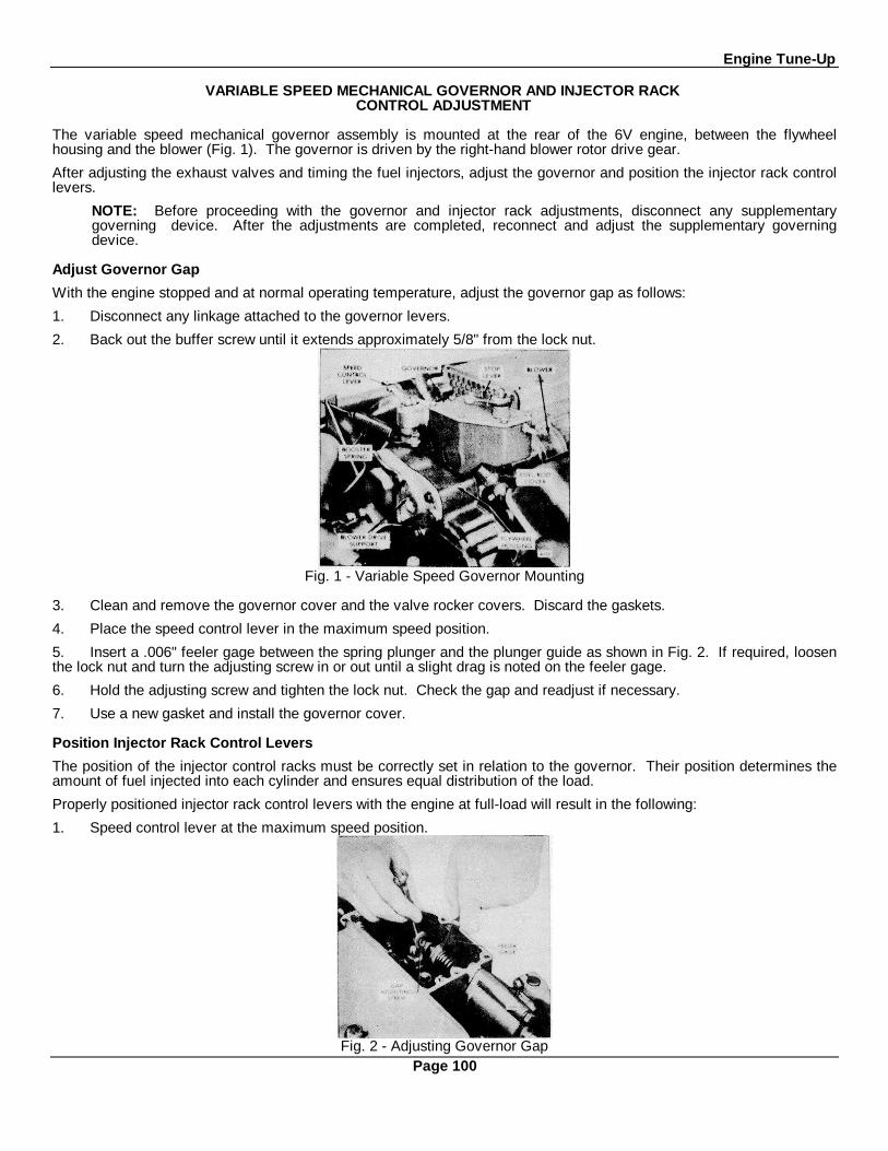
Engine Tune-Up
VARIABLE SPEED MECHANICAL GOVERNOR AND INJECTOR RACKCONTROL ADJUSTMENT
The variable speed mechanical governor assembly is mounted at the rear of the 6V engine, between the flywheelhousing and the blower (Fig. 1). The governor is driven by the right-hand blower rotor drive gear.
After adjusting the exhaust valves and timing the fuel injectors, adjust the governor and position the injector rack controllevers.
NOTE: Before proceeding with the governor and injector rack adjustments, disconnect any supplementarygoverning device. After the adjustments are completed, reconnect and adjust the supplementary governingdevice.
Adjust Governor Gap
With the engine stopped and at normal operating temperature, adjust the governor gap as follows:
1. Disconnect any linkage attached to the governor levers.
2. Back out the buffer screw until it extends approximately 5/8" from the lock nut.
Fig. 1 - Variable Speed Governor Mounting
3. Clean and remove the governor cover and the valve rocker covers. Discard the gaskets.
4. Place the speed control lever in the maximum speed position.
5. Insert a .006" feeler gage between the spring plunger and the plunger guide as shown in Fig. 2. If required, loosenthe lock nut and turn the adjusting screw in or out until a slight drag is noted on the feeler gage.
6. Hold the adjusting screw and tighten the lock nut. Check the gap and readjust if necessary.
7. Use a new gasket and install the governor cover.
Position Injector Rack Control Levers
The position of the injector control racks must be correctly set in relation to the governor. Their position determines theamount of fuel injected into each cylinder and ensures equal distribution of the load.
Properly positioned injector rack control levers with the engine at full-load will result in the following:
1. Speed control lever at the maximum speed position.
Fig. 2 - Adjusting Governor GapPage 100
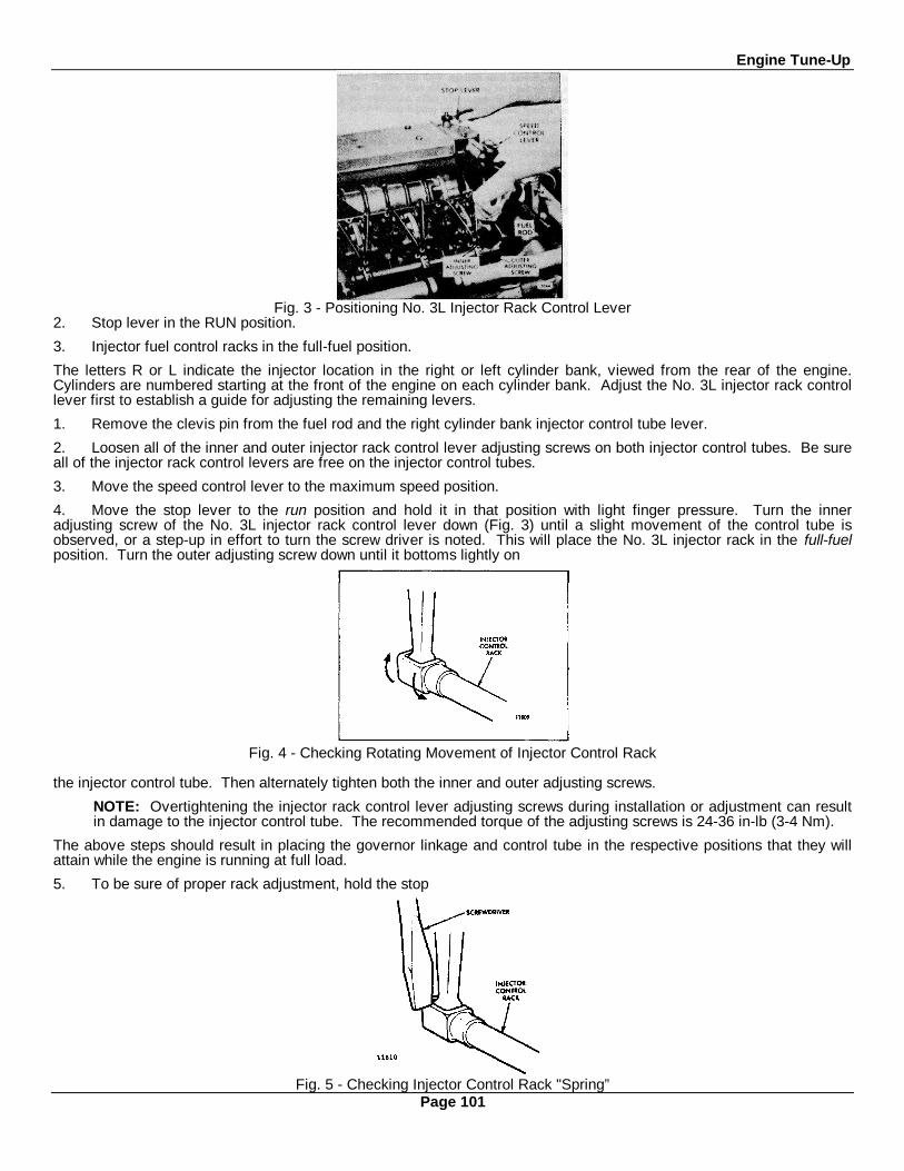
Engine Tune-Up
Fig. 3 - Positioning No. 3L Injector Rack Control Lever2. Stop lever in the RUN position.
3. Injector fuel control racks in the full-fuel position.
The letters R or L indicate the injector location in the right or left cylinder bank, viewed from the rear of the engine.Cylinders are numbered starting at the front of the engine on each cylinder bank. Adjust the No. 3L injector rack controllever first to establish a guide for adjusting the remaining levers.
1. Remove the clevis pin from the fuel rod and the right cylinder bank injector control tube lever.
2. Loosen all of the inner and outer injector rack control lever adjusting screws on both injector control tubes. Be sureall of the injector rack control levers are free on the injector control tubes.
3. Move the speed control lever to the maximum speed position.
4. Move the stop lever to the run position and hold it in that position with light finger pressure. Turn the inneradjusting screw of the No. 3L injector rack control lever down (Fig. 3) until a slight movement of the control tube isobserved, or a step-up in effort to turn the screw driver is noted. This will place the No. 3L injector rack in the full-fuelposition. Turn the outer adjusting screw down until it bottoms lightly on
Fig. 4 - Checking Rotating Movement of Injector Control Rack
the injector control tube. Then alternately tighten both the inner and outer adjusting screws.
NOTE: Overtightening the injector rack control lever adjusting screws during installation or adjustment can resultin damage to the injector control tube. The recommended torque of the adjusting screws is 24-36 in-lb (3-4 Nm).
The above steps should result in placing the governor linkage and control tube in the respective positions that they willattain while the engine is running at full load.
5. To be sure of proper rack adjustment, hold the stop
Fig. 5 - Checking Injector Control Rack "Spring”Page 101

Engine Tune-Uplever in the run position and press down on the injector rack with a screw driver or finger tip and note the "rotating"movement of the injector control rack (Fig. 4). Hold the stop lever in the run position and, using a screw driver, pressdownward on the injector control rack. The rack should tilt downward (Fig. 5) and when the pressure of the screw driveris released, the control rack should "spring" back upward. If the rack does not return to its original position, it is too loose.To correct this condition, back off the outer adjusting screw slightly and tighten the inner adjusting screw. The setting istoo tight if, when moving the stop lever from the stop to the run position, the injector rack becomes tight before thegovernor stop lever reaches the end of its travel. This will result in a step-up in effort required to move the stop lever tothe run position and a deflection in the fuel rod (fuel rod deflection can be seen at the bend). If the rack is found to betoo tight, back off the inner adjusting screw slightly and tighten the outer adjusting screw.
6. Remove the clevis pin from the fuel rod and the left bank injector control tube lever.
7. Insert the clevis pin in the fuel rod and the right cylinder bank injector control tube lever and position the No. 3Rinjector rack control lever as previously outlined in Step 4 for the No. 3L control lever.
8. Insert the clevis pin in the fuel rod and the left bank injector control tube lever. Repeat the check on the 3L and 3Rinjector rack control levers as outlined in Step 5. Check for and eliminate any deflection which may occur at the bend inthe fuel rod where it enters the cylinder head.
9. To adjust the remaining injector rack control levers, remove the clevis pin from the fuel rods and the injector controltube levers, hold the injector control racks in the full-fuel position by means of the lever on the end of the control tubeand proceed as follows:
a. Turn down the inner adjusting screw of the injector rack control lever until the screw bottoms (injector controlrack in the full-fuel position).
b. Turn down the outer adjusting screw of the injector rack control lever until it bottoms on the injector controltube.
c. While still holding the control tube lever in the full-fuel position, adjust the inner and outer adjusting screws toobtain the same condition as outlined in Step 5. Tighten the screws.
CAUTION: Once the No. 3L and No. 3R injector rack control levers are adjusted, do not try to alter their settings.All adjustments are made on the remaining control racks.
10. When all of the injector rack control levers are adjusted, recheck their settings. With the control tube lever in thefull-fuel position, check each control rack as in Step 5. All of the control racks must have the same "spring" conditionwith the control tube lever in the full-fuel position.
11. Insert the clevis pin in the fuel rods and the injector control tube levers.
12. Use new gaskets and install the valve rocker covers.
Adjust Maximum No-Load Speed
All governors are properly adjusted before leaving the factory. However, if the governor has been reconditioned orreplaced, and to ensure the engine speed will not exceed the recommended no-load speed as given on the engine optionplate, the maximum no-load speed may be set as follows:
Start the engine and after it reaches normal operating temperature, determine the maximum no-load speed of the enginewith an accurate tachometer. Then stop the engine and make the following adjustments, if required.
1. Refer to Fig. 9 and disconnect the booster spring and the stop lever retracting spring.
2. Remove the variable speed spring housing and the spring retainer, located inside of the housing, from the governorhousing.
3. Refer to Table I and determine the stops or shims required for the desired full-load speed. A split stop can only beused with a solid stop (Fig. 6).
4. Install the variable speed spring retainer and housing and tighten the two bolts.
Fig. 6 - Location of Shims and Stops
Page 102

Engine Tune-Up
Fig. 7 - Adjusting Idle Speed
Full-Load Speed Stops Shims*Solid Split
1200-21002100-2500
2500-2800
110
100
As RequiredAs RequiredAs Required
*Maximum amount of shims .325"TABLE 1
5. Connect the booster spring and the stop lever spring. Start the engine and recheck the maximum no-load speed.
6. If required, add shims to obtain the necessary operating speed. For each .001 1"in shims added, the operatingspeed will increase approximately 2 rpm.
IMPORTANT: If the maximum no-load speed is raised or lowered more than 50 rpm by the installation or removalof shims, recheck the governor gap. If readjustment of the governor gap is required, the position of the injectorracks must be rechecked.
NOTE: Governor stops are used to limit the compression of the governor spring, which determines the maximumspeed of the engine.
Adjust Idle Speed
With the maximum no-load speed properly adjusted, adjust the idle speed as follows:
1. Place the stop lever in the run position and the speed control lever in the idle position.
Fig. 8 - Adjusting Buffer Screw
2. With the engine running at normal operating temperature, back out the buffer screw to avoid contact with thedifferential lever.
3. Loosen the lock nut and turn the idle speed adjusting screw (Fig. 7) until the engine is operating at approximately15 rpm below the recommended idle speed. The recommended idle speed is 550 rpm, but may vary with special engineapplications.
4. Hold the idle speed adjusting screw and tighten the lock nut.
Adjust Buffer Screw
1. With the engine running at normal operating temperature, turn the buffer screw in (Fig. 8) so that it contacts thedifferential lever as lightly as possible and still eliminates engine roll.
NOTE: Do not raise the engine idle speed more than 15 rpm with the buffer screw.
2. Hold the buffer screw and tighten the lock nut.Adjust Booster Spring
With the idle speed adjusted, adjust the booster spring as follows:
1. Move the speed control lever to the idle speed position.
2. Refer to Fig. 9 and loosen the booster springPage 103

Engine Tune-Up
Fig. 9 - Adjusting Booster Spring
retaining nut on the speed control lever. Loosen the lock nuts on the eye bolt at the opposite end of the booster spring.
3. Move the spring retaining bolt in the slot of the speed control lever until the center of the bolt is on or slightly overcenter (toward the idle speed position) of an imaginary line through the bolt, lever shaft and eye bolt. Hold the bolt andtighten the lock nut.
4. Start the engine and move the speed control lever to the maximum speed position and release it. The speedcontrol lever should return to the idle position. If it does not, reduce the tension on the booster spring. If the lever doesreturn to the idle position, continue to increase the spring tension until the point is reached that it will not return to idle.Then reduce the tension until it does return to idle and tighten the lock nut on the eye bolt. This setting will result in theminimum force required to operate the speed control lever.
5. Connect the linkage to the governor levers.
Page 104
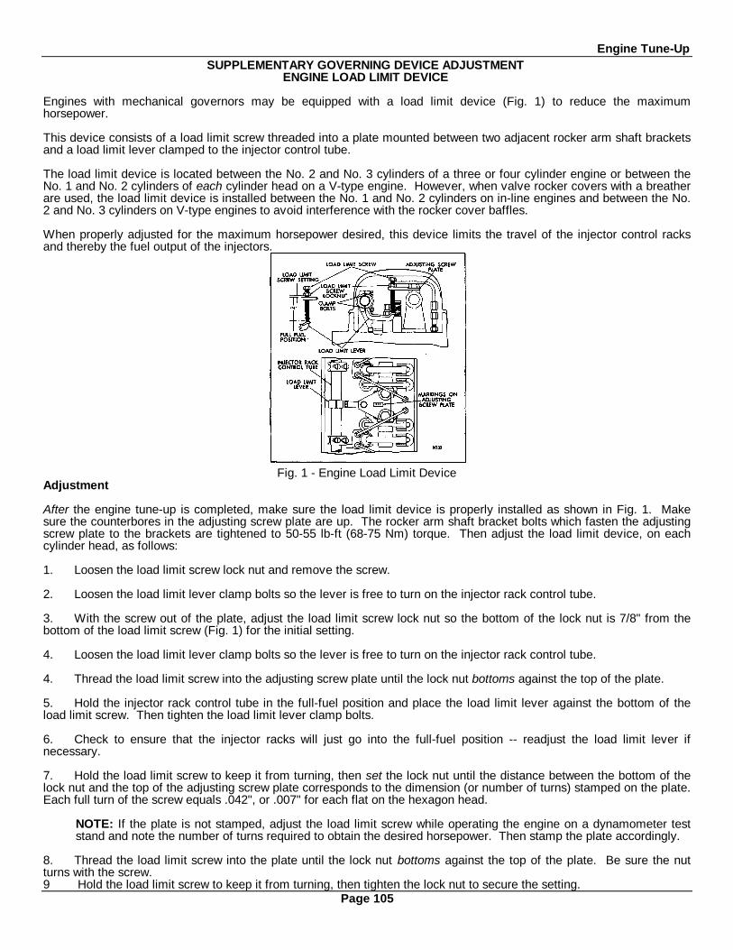
Engine Tune-UpSUPPLEMENTARY GOVERNING DEVICE ADJUSTMENT
ENGINE LOAD LIMIT DEVICE
Engines with mechanical governors may be equipped with a load limit device (Fig. 1) to reduce the maximumhorsepower.
This device consists of a load limit screw threaded into a plate mounted between two adjacent rocker arm shaft bracketsand a load limit lever clamped to the injector control tube.
The load limit device is located between the No. 2 and No. 3 cylinders of a three or four cylinder engine or between theNo. 1 and No. 2 cylinders of each cylinder head on a V-type engine. However, when valve rocker covers with a breatherare used, the load limit device is installed between the No. 1 and No. 2 cylinders on in-line engines and between the No.2 and No. 3 cylinders on V-type engines to avoid interference with the rocker cover baffles.
When properly adjusted for the maximum horsepower desired, this device limits the travel of the injector control racksand thereby the fuel output of the injectors.
Fig. 1 - Engine Load Limit DeviceAdjustment
After the engine tune-up is completed, make sure the load limit device is properly installed as shown in Fig. 1. Makesure the counterbores in the adjusting screw plate are up. The rocker arm shaft bracket bolts which fasten the adjustingscrew plate to the brackets are tightened to 50-55 lb-ft (68-75 Nm) torque. Then adjust the load limit device, on eachcylinder head, as follows:
1. Loosen the load limit screw lock nut and remove the screw.
2. Loosen the load limit lever clamp bolts so the lever is free to turn on the injector rack control tube.
3. With the screw out of the plate, adjust the load limit screw lock nut so the bottom of the lock nut is 7/8" from thebottom of the load limit screw (Fig. 1) for the initial setting.
4. Loosen the load limit lever clamp bolts so the lever is free to turn on the injector rack control tube.
4. Thread the load limit screw into the adjusting screw plate until the lock nut bottoms against the top of the plate.
5. Hold the injector rack control tube in the full-fuel position and place the load limit lever against the bottom of theload limit screw. Then tighten the load limit lever clamp bolts.
6. Check to ensure that the injector racks will just go into the full-fuel position -- readjust the load limit lever ifnecessary.
7. Hold the load limit screw to keep it from turning, then set the lock nut until the distance between the bottom of thelock nut and the top of the adjusting screw plate corresponds to the dimension (or number of turns) stamped on the plate.Each full turn of the screw equals .042", or .007" for each flat on the hexagon head.
NOTE: If the plate is not stamped, adjust the load limit screw while operating the engine on a dynamometer teststand and note the number of turns required to obtain the desired horsepower. Then stamp the plate accordingly.
8. Thread the load limit screw into the plate until the lock nut bottoms against the top of the plate. Be sure the nutturns with the screw.9 Hold the load limit screw to keep it from turning, then tighten the lock nut to secure the setting.
Page 105

Engine Tune-UpThe throttle delay mechanism is used to retard full-fuel injection when the engine is accelerated. This reduces exhaustsmoke and also helps to improve fuel economy.
The throttle delay mechanism (Fig. 2) is installed between the No. I and No. 2 cylinders on three cylinder engines,between the No. 2 and No. 3 cylinders on four cylinder engines, or between the No. 1 and No. 2 cylinders on the right-bank cylinder head of V-type engines. It consists of a special rocker arm shaft bracket (which incorporates the throttledelay cylinder), a piston, throttle delay lever, connecting link, oil supply plug, ball check valve and U-bolt.
A yield lever and spring assembly replaces the standard lever and pin assembly on the rear end of the injector controltube on In-line engines (Fig. 3). A yield lever replaces the standard operating lever in the governor of the 6V-53 engine(Fig. 4).
Operation
Oil is supplied to a reservoir above the throttle delay cylinder through a special plug in the drilled oil passage in therocker arm shaft bracket (Fig. 2). As the injector racks are moved toward the no-fuel position, free movement of thethrottle delay piston is assured by air drawn into the cylinder through the ball check valve. Further movement of thepiston uncovers an opening which permits oil from the reservoir to enter the cylinder and displace the air. When the
Fig. 2 - Throttle Delay Cylinder
Fig. 3 - Throttle Delay Yield Lever (In-Line Engine)
engine is accelerated, movement of the injector racks toward the full-fuel position is momentarily retarded while thepiston expels the oil from the cylinder through a .016" orifice. To permit full accelerator travel, regardless of the retardedinjector rack position, a spring loaded yield lever or link assembly replaces the standard operating lever connecting link tothe governor.
InspectionWhen inspecting the throttle delay hydraulic cylinder, it is important that the check valve be inspected for wear. Replacethe check valve if necessary.
Fig. 4 - Throttle Delay Yield Lever (6V Engine)Page 106
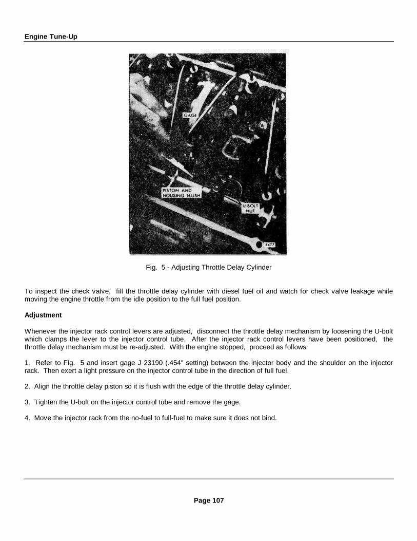
Engine Tune-Up
Fig. 5 - Adjusting Throttle Delay Cylinder
To inspect the check valve, fill the throttle delay cylinder with diesel fuel oil and watch for check valve leakage whilemoving the engine throttle from the idle position to the full fuel position.
Adjustment
Whenever the injector rack control levers are adjusted, disconnect the throttle delay mechanism by loosening the U-boltwhich clamps the lever to the injector control tube. After the injector rack control levers have been positioned, thethrottle delay mechanism must be re-adjusted. With the engine stopped, proceed as follows:
1. Refer to Fig. 5 and insert gage J 23190 (.454" setting) between the injector body and the shoulder on the injectorrack. Then exert a light pressure on the injector control tube in the direction of full fuel.
2. Align the throttle delay piston so it is flush with the edge of the throttle delay cylinder.
3. Tighten the U-bolt on the injector control tube and remove the gage.
4. Move the injector rack from the no-fuel to full-fuel to make sure it does not bind.
Page 107

Engine Tune-Up
ADJUSTMENT OF MECHANICAL GOVERNOR SHUTDOWN SOLENOID
Fig. 6 - Typical Speed Governor Lever Fig. 7 - Typical Limiting Speed Governor LeverPosition Position
When a governor shutdown solenoid is used on an engine equipped with a mechanical governor, the governor stop levermust be properly adjusted to match the shutdown solenoid plunger travel.
The solenoid plunger can be properly aligned to the governor stop lever as follows:
1. Remove the bolt connecting the rod end eye (variable speed governor), or the right angle clip (limiting speedgovernor) to the stop lever (Figs. 6 and 7). Align and clamp the lever to the shutdown shaft in such a way that, at itsmid-travel position, it is perpendicular to the solenoid plunger. This assures that the linkage will travel as straight aspossible. The solenoid plunger has available 1/2" travel which is more than adequate to move the injector control racksfrom the full-fuel to the complete no-fuel position and shutdown will occur prior to attaining complete travel.
2. With the stop lever in the run position, adjust the rod end eye or right angle clip for minimum engagement on thesolenoid plunger when the connecting bolt is installed. The oversize hole in the eye or clip will thereby permit thesolenoid to start closing the air gap, with a resultant build-up of pull-in force prior to initiating stop lever movement.
3. The bolt through the rod end eye or the right angle clip should be locked to the stop lever and adjusted to a height thatwill permit the eye or clip to float vertically. The clearance above and below the eye or clip and the bolt head should beapproximately 1/32 " minimum.
NOTE: The lock nut can be either on top of or below the stop lever.
4. Move the lever to the stop position and observe the plunger for any possible bind. If necessary, loosen the mountingbolts and realign the solenoid to provide free plunger motion.
Page 108
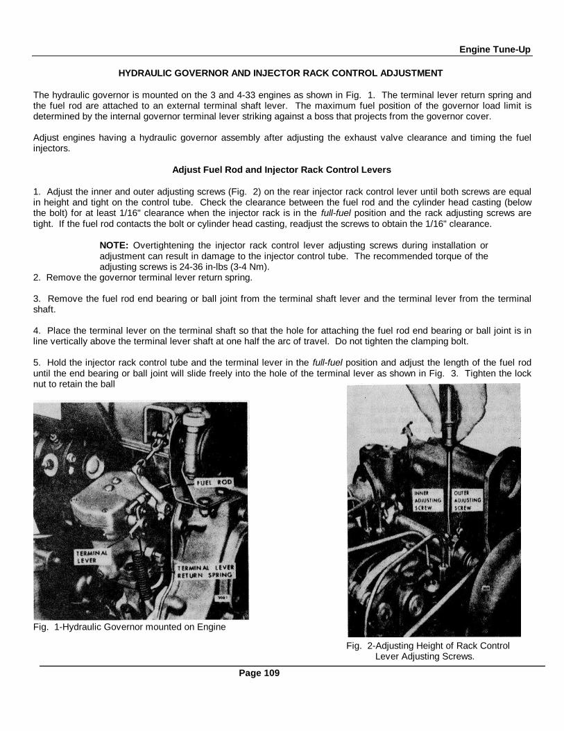
Engine Tune-Up
HYDRAULIC GOVERNOR AND INJECTOR RACK CONTROL ADJUSTMENT
The hydraulic governor is mounted on the 3 and 4-33 engines as shown in Fig. 1. The terminal lever return spring andthe fuel rod are attached to an external terminal shaft lever. The maximum fuel position of the governor load limit isdetermined by the internal governor terminal lever striking against a boss that projects from the governor cover.
Adjust engines having a hydraulic governor assembly after adjusting the exhaust valve clearance and timing the fuelinjectors.
Adjust Fuel Rod and Injector Rack Control Levers
1. Adjust the inner and outer adjusting screws (Fig. 2) on the rear injector rack control lever until both screws are equalin height and tight on the control tube. Check the clearance between the fuel rod and the cylinder head casting (belowthe bolt) for at least 1/16" clearance when the injector rack is in the full-fuel position and the rack adjusting screws aretight. If the fuel rod contacts the bolt or cylinder head casting, readjust the screws to obtain the 1/16" clearance.
NOTE: Overtightening the injector rack control lever adjusting screws during installation oradjustment can result in damage to the injector control tube. The recommended torque of theadjusting screws is 24-36 in-lbs (3-4 Nm).
2. Remove the governor terminal lever return spring.
3. Remove the fuel rod end bearing or ball joint from the terminal shaft lever and the terminal lever from the terminalshaft.
4. Place the terminal lever on the terminal shaft so that the hole for attaching the fuel rod end bearing or ball joint is inline vertically above the terminal lever shaft at one half the arc of travel. Do not tighten the clamping bolt.
5. Hold the injector rack control tube and the terminal lever in the full-fuel position and adjust the length of the fuel roduntil the end bearing or ball joint will slide freely into the hole of the terminal lever as shown in Fig. 3. Tighten the locknut to retain the ball
Fig. 1-Hydraulic Governor mounted on Engine
Fig. 2-Adjusting Height of Rack ControlLever Adjusting Screws.
Page 109
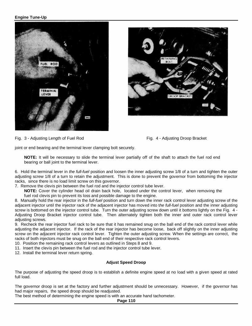
Engine Tune-Up
Fig. 3 - Adjusting Length of Fuel Rod Fig. 4 - Adjusting Droop Bracket
joint or end bearing and the terminal lever clamping bolt securely.
NOTE: It will be necessary to slide the terminal lever partially off of the shaft to attach the fuel rod endbearing or ball joint to the terminal lever.
6. Hold the terminal lever in the full-fuel position and loosen the inner adjusting screw 1/8 of a turn and tighten the outeradjusting screw 1/8 of a turn to retain the adjustment. This is done to prevent the governor from bottoming the injectorracks, since there is no load limit screw on this governor.7. Remove the clevis pin between the fuel rod and the injector control tube lever.
NOTE: Cover the cylinder head oil drain back hole, located under the control lever, when removing thefuel rod clevis pin to prevent its loss and possible damage to the engine.
8. Manually hold the rear injector in the full-fuel position and turn down the inner rack control lever adjusting screw of theadjacent injector until the injector rack of the adjacent injector has moved into the full-fuel position and the inner adjustingscrew is bottomed on the injector control tube. Turn the outer adjusting screw down until it bottoms lightly on the Fig. 4 -Adjusting Droop Bracket injector control tube. Then alternately tighten both the inner and outer rack control leveradjusting screws.9. Recheck the rear injector fuel rack to be sure that it has remained snug on the ball end of the rack control lever whileadjusting the adjacent injector. If the rack of the rear injector has become loose, back off slightly on the inner adjustingscrew on the adjacent injector rack control lever. Tighten the outer adjusting screw. When the settings are correct, theracks of both injectors must be snug on the ball end of their respective rack control levers.10. Position the remaining rack control levers as outlined in Steps 8 and 9.11. Insert the clevis pin between the fuel rod and the injector control tube lever.12. Install the terminal lever return spring.
Adjust Speed Droop
The purpose of adjusting the speed droop is to establish a definite engine speed at no load with a given speed at ratedfull load.
The governor droop is set at the factory and further adjustment should be unnecessary. However, if the governor hashad major repairs, the speed droop should be readjusted.The best method of determining the engine speed is with an accurate hand tachometer.
Page 110

Engine Tune-Up
Full Load No-Load50 cycles 1000 rpm 52.5 cycles 1050 rpm60 cycles 1200 rpm 62.5 cycles 1250 rpm50 cycles 1500 rpm 52.5 cycles 1575 rpm60 cycles 1800 rpm 62.5 cycles 1875 rpm
TABLE 1
If a full-rated load can be established on the engineand the fuel rod, injector rack control levers and loadlimit have been adjusted, the speed droop may beadjusted as follows:
I. Start the engine and run it at approximately one-half the rated no-load speed until the lubricating oiltemperature stabilizes.
NOTE: When the engine lubricating oil is cold,the governor regulation may be erratic. Theregulation should become increasingly stable asthe temperature of the lubricating oil increases. Figure 5 - Adjusting Maximum Engine Speed
2. Stop the engine and remove the governor cover. Discard the gasket.3. Loosen the lock nut and back off the maximum speed adjusting screw (Fig. 5) approximately 5/8"
4. Refer to Fig. 4 and loosen the droop adjusting bolt. Move the droop bracket so that the bolt is midway between theends of the slot in the bracket. Tighten the bolt.
5. With the throttle in the run position, adjust the engine speed until the engine is operating at 3% to 5%above the recommended full-load speed.
6. Apply the full-rated load on the engine and readjust the engine speed to the correct full-load speed.7. Remove the rated load and note the engine speed after the speed stabilizes under no-load. If the speed droop iscorrect, the engine speed will be approximately 3% to 5% higher than the full-load speed.
If the speed droop is too high, stop the engine and again loosen the droop bracket retaining bolt and move the droopadjusting bracket in toward the engine. Tighten the bolt. To increase the speed droop, move the droop adjusting bracketout, away from the engine.
The speed droop in governors which control engines driving generators in parallel must be identical, otherwise, theelectrical load will not be equally divided.
Adjust the speed droop bracket in each engine governor to obtain the desired variation between the engine no-load andfull-load speeds shown in Table 1.The recommended speed droop of generator sets operating in parallel is 50 rpm (2-1/2 cycles) for units operating at 1000and 1200 rpm and 75 rpm (2-1/2 cycles) for units operating at 1500 rpm and 1800 rpm full load. This speed drooprecommendation may be varied to suit the individual application.
Adjust Maximum No- Load SpeedWith the speed droop properly adjusted, set the maximum no-load speed as follows:1. Loosen the maximum speed adjusting screw lock nut and back out the maximum speed adjusting screw three turns.2. With the engine operating at no-load, adjust the engine speed until the engine is operating at approximately 8%higher than the rated full-load speed.3. Turn the maximum speed adjusting screw (Fig. 5) in lightly until contact is felt with the linkage in the governor.4. Hold the maximum speed adjusting screw and tighten the lock nut.5. Use a new gasket and install the governor cover.
Page 111

Engine Tune-Up
HYDRAULIC GOVERNOR AND INJECTOR RACK CONTROL ADJUSTMENT6V-53 Engine
Fig. 1 - Hydraulic Governor Mounting Fig. 2 - Hydraulic Governor ControlsThe hydraulic governor Is mounted between the blower and the rear end plate as shown in Fig. 1. The vertical controllink assembly is attached .to the governor operating lever and the bell crank lever on the governor drive housing (Fig. 2).
After adjusting the exhaust valves and timing the fuel injectors, adjust the governor as follows:
1. Disconnect the vertical control link assembly from the governor operating lever.
2. Loosen all of the injector rack control lever adjusting screws.
3. While holding the bell crank lever (on the governor drive housing) in a horizontal position (full-fuel), set the No. 3injector rack control levers on each bank to full-fuel.
4. Position the remaining rack control levers to the No. 3 control levers.
5. Remove the governor cover. Discard the gasket.
6. To determine the full-fuel position of the terminal lever, adjust the load limit screw to obtain a distance of 2" from theoutside face of the boss on the governor sub-cap to the end of the screw.
7. Adjust the operating lever (on the governor) so that it is horizontal, or slightly below (as close as the serrations on theshaft will permit) when the shaft is rotated to the full-fuel position, or clockwise when viewed from the front of the engine.
8. Loosen the lock nut and adjust the length of the vertical link assembly, attached to the bell crank lever, to match thefull-fuel position of the governor operating lever and the injector rack control levers. This length should beapproximately 6-5/16". Tighten the lock nut.
9. With the governor operating lever held in the full-fuel position, turn the load limit screw ((Fig. 1) inward until theinjector racks just loosen on the ball end of the control levers, to prevent the injector racks from bottoming.
10. Release the governor operating lever and hold the adjusting screw while tightening the lock nut.
11. Use new gaskets and install the governor cover and the valve rocker covers.
Page 112

STORAGEPREPARING ENGINE FOR STORAGE
When an engine is to be stored or removed from operation for a period of time, special precautions should be taken toprotect the interior and exterior of the engine, transmission and other parts from rust accumulation and corrosion. Theparts requiring attention and the recommended preparations are given below.
It will be necessary to remove all rust or corrosion completely from any exposed part before applying a rust preventivecompound. Therefore, it is recommended that the engine be processed for storage as soon as possible after removalfrom operation.
The engine should be stored in a building which is dry and can be heated during the winter months. Moisture absorbingchemicals are available commercially for use when excessive dampness prevails in the storage area.To protect an engine for a temporary period of time, proceed as follows:1. Drain the engine crankcase.2. Fill the crankcase to the proper level with the recommended viscosity and grade of oil.3. Fill the fuel tank with the recommended grade of fuel oil. Operate the engine for two minutes at 1200 rpm and noload.
NOTE: Do not drain the fuel system or the crankcase after this run.4. Check the air cleaner and service it, if necessary, as outlined under Air System.5. If freezing weather is expected during the storage period, add a high boiling point type antifreeze solution in,accordance with the manufacturer's recommendations. Drain the raw water system and leave the drain cocks open.6. Clean the entire exterior of the engine (except the electrical system) with fuel oil and dry it with air.7. Seal all of the engine openings. The material used for this purpose must be waterproof, vaporproof and possesssufficient physical strength to resist puncture and damage from the expansion of entrapped air.
An engine prepared in this manner can be returned to service in a short time by removing the seals at the engineopenings, checking the engine coolant, fuel oil, lubricating oil, transmission, and priming the raw water pump, if used.When an engine is to be removed from operation for an extended period of time, prepare it as follows:
1. Drain and thoroughly flush the cooling system with clean, soft water.2. Refill the cooling system with clean, soft water.3. Add a rust inhibitor to the cooling system (refer to Corrosion Inhibitor under Cooling System).4. Remove, check and recondition the injectors, if necessary, to make sure they will be ready to operate when theengine is restored to service.5. Reinstall the injectors in the engine, time them, and adjust the valve clearance.6. Circulate the coolant through the entire system by operating the engine until normal operating temperature is reached(160-185 F or 71-85 ° C).7. Stop the engine.8. Remove the drain plug and completely drain the engine crankcase. Reinstall and tighten the drain plug. Install newlubricating oil filter elements and gaskets.9. Fill the crankcase to the proper level with a 30-weight preservative lubricating oil MIL-L-21260, Grade 2 (P10), orequivalent.10. Drain the engine fuel tank.11. Refill the fuel tank with enough rust preventive fuel oil such as American Oil Diesel Run-In Fuel (LF
Page 113

Storage4089), Mobil 4Y17, or equivalent, to enable the engine to operate 10 minutes.12. Drain the fuel filter and strainer. Remove the retaining bolts, shells and elements. Discard the used elements andgaskets. Wash the shells in clean fuel oil and insert new elements. Fill the cavity between the element and shell abouttwo-thirds full of the same rust preventive compound as used in the fuel tank and reinstall the shell.13. Operate the engine for 10 minutes to circulate the rust preventive throughout the engine.14. Refer to Air System and service the air cleaner.15. MARINE GEAR
a. Drain the oil completely and refill with clean oil of the proper viscosity and grade as is recommended.Remove, clean or replace the strainer and replace the filter element.
b. Start and run the engine at 600 rpm for 5 minutes so that clean oil can coat all of the internal parts of themarine gear. Engage the clutches alternately to circulate clean oil through all of the moving parts.
16. TORQMATIC CONVERTER
a. Start the engine and operate it until the temperature of the converter oil reaches 150°F (66 0 C).b. Remove the drain plug and drain the converter.c. Remove the filter element.d. Start the engine and stall the converter for twenty seconds at 1000 rpm to scavenge the oil from the
converter. Due to lack of lubrication, do not exceed the 20 second limit.e. Install the drain plug and a new filter element.f. Fill the converter to the proper operating level with a commercial preservative oil which meets Government
specifications MIL-L-2 1260, Grade 1. Oil of this type is available from the major oil companies.g. Start the engine and operate the converter for at least 10 minutes at a minimum of 1000 rpm. Engage the
clutch; then stall the converter to raise the oil temperature to 225 0 F (107 ° C).
CAUTION: Do not allow the oil temperature to exceed 225 F (107°C). If the unit does not have atemperature gage, do not stall the converter for more than thirty seconds.
h. Stop the engine and permit the converter to cool to a temperature suitable to touch.i. Seal all of the exposed openings and the breather with moisture proof tape.j. Coat all exposed, unpainted surfaces with preservative grease. Position all of the controls for minimum
exposure and coat them with grease. The external shafts, flanges and seals should also be coated withgrease.
17. POWER TAKE-OFFa. With an all purpose grease such as Shell Alvania No. 2, or equivalent, lubricate the clutch throwout bearing,
clutch pilot bearing, drive shaft main bearing, clutch release shaft, and the outboard bearings (if soequipped).
b. Remove the inspection hole cover on the clutch housing and lubricate the clutch release lever and link pinswith a hand oiler. Avoid getting oil on the clutch facing.
c. If the unit is equipped with a reduction gear, drain and flush the gear box with light engine oil. If the unit isequipped with a filter, clean the shell and replace the filter element. Refill the gear box to the proper levelwith the oil grade indicated on the name plate.
18. TURBOCHARGERThe turbocharger bearings are lubricated by pressure through the external oil line leading from the engine cylinder blockwhile performing the previous operations above and no further attention is required. However, the turbocharger air inletand turbine outlet connections should be sealed off with moisture-resistant tape.19. HYDROSTARTER SYSTEMRefer to Hydraulic Starting System in the section on Engine Equipment for the lubrication and preventive maintenanceprocedure.20. Apply a non-friction rust preventive compound, to all exposed parts. If it is convenient, apply the rust preventivecompound to the engine flywheel. If not, disengage the clutch mechanism to prevent the clutch disc from sticking to theflywheel.
Page 114

StorageCAUTION: Do not apply oil, grease or any wax base compound to the flywheel. The cast iron will absorbthese substances which can "sweat" out during operation and cause the clutch to slip.
21. Drain the engine cooling system.22. The oil may be drained from the engine crankcase if so desired. If the oil is drained, reinstall and tighten the drainplug.23. Remove and clean the battery and battery cables with a baking soda solution and rinse them with fresh water. Donot allow the soda solution to enter the battery. Add distilled water to the electrolyte, if necessary, and fully charge thebattery. Store the battery in a cool (never below 32 ° F or 0°C) dry place. Keep the battery fully charged and check thelevel and the specific gravity of the electrolyte regularly.24. Insert heavy paper strips between the pulleys and belts to prevent sticking.25. Seal all of the openings in the engine, including the exhaust outlet, with moisture resistant tape. Use cardboard,plywood or metal covers where practical.26. Clean and dry the exterior painted surfaces of the engine. Spray the surfaces with a suitable liquid automobile bodywax, a synthetic resin varnish or a rust preventive compound.27. Cover the engine with a good weather-resistant tarpaulin or other cover if it must be stored outdoors. A clear plasticcover is recommended for indoor storage. The stored engine should be inspected periodically. If there are anyindications of rust or corrosion, corrective steps must be taken to prevent damage to the engine parts. Perform acomplete inspection at the end of one year and apply additional treatment as required.
PROCEDURE FOR RESTORING AN ENGINE TO SERVICE WHICH HAS BEEN IN EXTENDED STORAGE
1. Remove the covers and tape from all of the openings of the engine, fuel tank, and electrical equipment. Do notoverlook the exhaust outlet.2. Wash the exterior of the engine with fuel oil to remove the rust preventive.3. Remove the rust preventive from the flywheel.4. Remove the paper strips from between the pulleys and the belts.5. Remove the drain plug and drain the preservative oil from the crankcase. Re-install the drain plug. Then refer toLubrication System in the Operating Instructions and fill the crankcase to the proper level with the recommended grade oflubricating oil.6. Fill the fuel tank with the fuel specified under Diesel Fuel Oil Specifications.7. Close all of the drain cocks and fill the engine cooling system with clean soft water and a rust inhibitor. If the engineis to be exposed to freezing temperatures, add a high boiling point type antifreeze solution to the cooling system (theantifreeze contains a rust inhibitor).8. Install and connect the battery.9. Service the air cleaner as outlined under Air System.10. POWER GENERATOR
Prepare the generator for starting as outlined under Operating Instructions.11. MARINE GEARCheck the Marine gear; refill it to the proper level, as necessary, with the correct grade of lubricating oil.12. TORQMATIC CONVERTER
a. Remove the tape from the breather and all of the openings.b. Remove all of the preservative grease with a suitable solvent.c. Start the engine and operate the unit until the temperature reaches 150°F (66°C). Drain the preservative oil
and remove the filter. Start the engine and stall the converter for twenty seconds at 1000 rpm to scavengethe oil from the converter.
CAUTION: A Torqmatic converter containing preservative oil should only be operated enough to bring theoil temperature up to 150°F (66 0 C).d. Install the drain plug and a new filter element.
Page 115
Storage
e. Refill the converter with the oil that is recommended under Lubrication and PreventiveMaintenance.
13. POWER TAKE-OFF
Remove the inspection hole cover and inspect the clutch release lever and link pins and the bearing ends of the clutchrelease shaft. Apply engine oil sparingly, if necessary, to these areas.
14. HYDROSTARTER
a. Open the relief valve on the side of the hand pump and release the pressure in the system.
b. Refer to the filling and' purging procedures outlined in Hydraulic Starting System. Then, drain, refill andpurge the hydrostarter system.
15. TURBOCHARGERRemove the covers from the turbocharger air inlet and turbine outlet connections. Refer to the lubricating procedureoutlined in Preparation for Starting Engine First Time.16. After all of the preparations have been completed, start the engine. The small amount of rust preventive compoundwhich remains in the fuel system will cause a smoky exhaust for a few minutes.
NOTE: Before subjecting the engine to a load or high speed, it is advisable to check the engine tune-up.
Page 116
Page 117

Built-in Parts Book
Progress in industry comes at a rapid pace. In order for the engine manufacturerto keep pace with progress he needs a versatile product for the many models andarrangements of accessories and mounting parts needed to suit a variety ofequipment. In addition, engine refinements and improvements are constantlybeing introduced. All of this dynamic action must be documented so that theequipment can be serviced if and when it's needed. It is fully documented in themanufacturer's plant and in dealer Parts Departments with Master Files andadequate supporting records. But, what about YOU the user of this equipment?You have neither the time nor the inclination to ferret out specific part numberdata. What is the answer?-It is Detroit Diesel's exclusive BUILT-IN PARTS BOOKwhich is furnished with each engine. It takes the form of an "Option Plate"mounted on the rocker cover of the engine. With it, ordering parts becomes assimple as A, B, C. You have merely to provide the Dealer with ...
A. The "Model" number B. The "UNIT" number C. The "TYPE" number
From that much information, the dealer with his complete records on all enginemodels, can completely interpret your parts requirements.
Page 118

Built-In Parts Book
What is this "built-in" book? It is a photo etched aluminum plate that fits intoa holding channel on the engine rocker cover.
ON THE RIGHT SIDE of the plate is shown the model number, serialnumber and the related governor setting.
Page 119

Built-In Parts Book
All engine components are divided into groups of functionally related parts. A complete listing of the twelve majorgroups and their many sub-groups is shown below.
Page 120
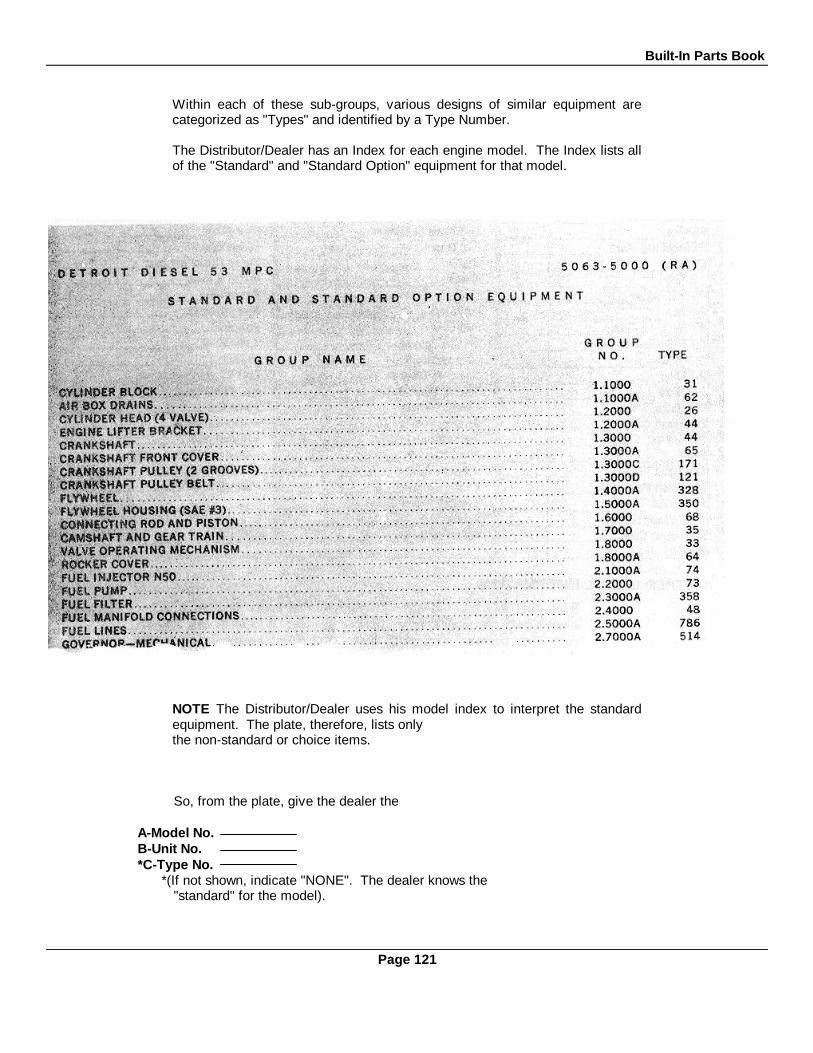
Built-In Parts Book
Within each of these sub-groups, various designs of similar equipment arecategorized as "Types" and identified by a Type Number.
The Distributor/Dealer has an Index for each engine model. The Index lists allof the "Standard" and "Standard Option" equipment for that model.
NOTE The Distributor/Dealer uses his model index to interpret the standardequipment. The plate, therefore, lists onlythe non-standard or choice items.
So, from the plate, give the dealer the
A-Model No.B-Unit No.*C-Type No.
*(If not shown, indicate "NONE". The dealer knows the"standard" for the model).
Page 121

Built-In Parts Book
FOR READY REFERENCE, Transfer the information on the Option Plate to this record.
OTHER USEFUL INFORMATION:
Each fuel and lube oil filter on your engine has a decal giving the service package partnumber for the element. It is advisable to have your own personal record of these partnumbers by filling in the chart provided below:
AIR CLEANERIf dry-type, indicate make and number of filter element:
Wet type, indicate capacity qts.
Page 122

Built-In Parts Book
CYLINDER HEAD
P 628
Page 123
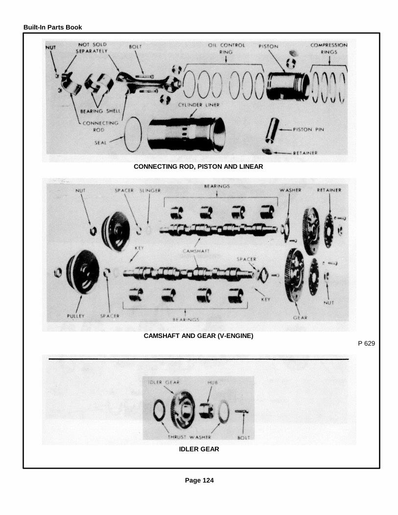
Built-In Parts Book
CONNECTING ROD, PISTON AND LINEAR
CAMSHAFT AND GEAR (V-ENGINE)P 629
IDLER GEAR
Page 124

Built-In Parts Book
ACCESSORY DRIVE FOR BELT DRIVEN ACCESSORY (DRIVE HUB TYPE)
ACCESSORY DRIVE FOR DIRECT DRIVEN ACCESSORY (CAMSHAFT GEAR)
Page 125

Built-In Parts Book
Page 127
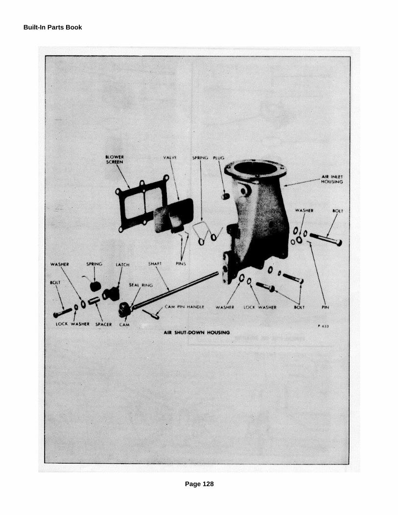
Built-In Parts Book
Page 128
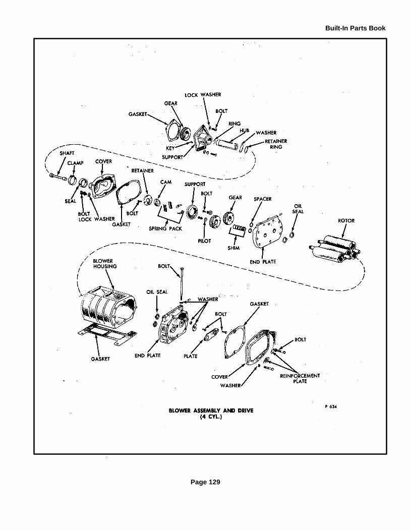
Built-In Parts Book
Page 129

Built-In Parts Book
Page 130
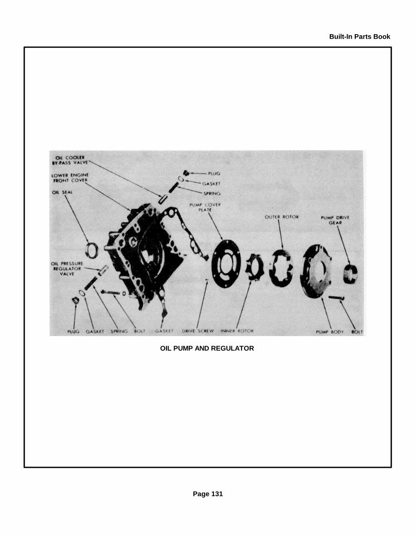
Built-In Parts Book
OIL PUMP AND REGULATOR
Page 131

Built-In Parts Book
OIL FILTER
OIL COOLERP 637
Page 132
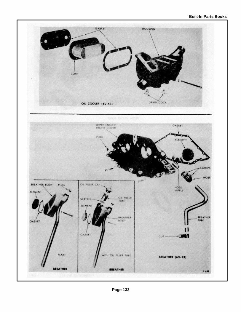
Built-In Parts Books
Page 133

Built-In Parts Book
FRESH WATER PUMP
THERMOSTAT (6V-53P 639
Page 134
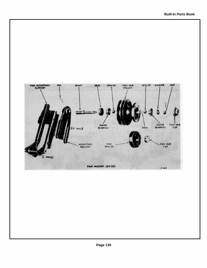
Built-In Parts Book
Page 135

Built-In Parts Book
FAN MOUNT
HEAT EXCHANGERP 641
Page 136

Built-In Parts Book
Page 137

Built-In Parts Book
Page 138

Built-In Parts Books
Page 139
Owner AssistanceOWNER ASSISTANCE
The satisfaction and goodwill of the owners of Detroit Diesel engines are of primary concern to the Detroit Diesel AllisonDivision, its distributors and their dealers.
As an owner of a Detroit Diesel engine, you have a complete network of over 2300 Detroit Diesel Allison Distributors andDealers in the U.S. and Canada, plus many outlets worldwide that are prepared and anxious to meet your parts andservice needs:
Expert service by trained personnel.
Emergency service 24 hours a day.
Complete parts support, including reliabilt components.
Sales teams to help determine your power requirements.
Product information and literature.
We recognize, however, that despite the best intentions of everyone concerned, misunderstandings may occur.Normally, any such situation that arises in connection with the sale, operation or service of your engine will be handled bythe distributor or dealer in your area (check the Yellow Pages for the Detroit Diesel Allison Service Outlet nearest you).
To further assure your complete satisfaction, we have developed the following three-step procedure to be followedin the event you have a problem that has not been handled satisfactorily.
Step One - Discuss your problem with a member of management from the distributorship or dealership.Frequently, complaints are the result of a breakdown in communication and can quickly be resolved by a member ofmanagement. If you have already discussed the problem with the Sales or Service Manager, contact the GeneralManager. If your problem originates with a dealer, explain the matter to a management member of the distributorshipwith whom the dealer has his service agreement.
Step Two - When it appears that your problem cannot readily be resolved at the distributor level without additionalassistance, contact the Detroit Diesel Allison Regional Office nearest you listed below:
Eastern Region Southeastern RegionSuite 202 5730 Glenridge Drive, N.E.10 Parsonage Road Atlanta, Georgia 30328Edison, New Jersey 08817 Phone: (404) 252-3310Phone: (201) 246-5074 Regional Manager: L. R. KirbyRegional Manager: S. F. Zappia Service Manager: B. D. Robison, Jr.Service Manager: D. P. Friedrich
Great Lakes Region Midwestern RegionGarrison Place Suite 61819855 Outer Drive 2021 Spring RoadDearborn, Michigan 48124 Oak Brook, Illinois 60521Phone: (313) 565-0411 Phone: (312) 654-6619Regional Manager: A. W. Christy Regional Manager: C. O. ZimmermanService Manager: R. Schwaller Service Manager: T. F. Chope
Southwestern Region Northwestern RegionSuite 130 Suite 2502655 Villa Creek Drive 20380 Town Center LaneDallas, Texas 75234 Cupertino, California 95014Phone: (214) 241-7721 Phone: (408) 255-7700Regional Manager: F. A. Skells Regional Manager: W. C. EdwardsService Manager: W. C. Kaphengst Service Manager: J. P. Miles
Page 141
Owner Assistance
Western RegionSuite 823Crocker Bank Building15760 Ventura Blvd.Encino, California 91436Phone: (213) 981-7300Regional Manager: G. J. DunnebackService Manager: W. K. Clark, Jr.
Prior to this call, have the following information available:
Name and location of distributor or dealer.Type and make of equipment.Engine model and serial number.Engine delivery date and accumulated
miles or hours of operation.Nature of problem.Chronological summary of unit's history.
Step Three - If you are still not satisfied, present the entire matter in writing or by phone to the Home Office:
Diesel Operations - J. E. Fisher, Manager Customer Services, Detroit Diesel Allison, 13400 W. Outer Drive,Detroit, Michigan 48228, Phone (313) 592-5608.
Canada Operations - E. A. Kobe, Manager of Product Service, Diesel Division, General Motors of Canada, Ltd.,P.O. Box 5990, 847 Highbury Avenue, London, Ontario N6A 4L6, Phone (519) 455-7110.
If at this point your problem is still not resolved to your satisfaction, call or write J. P. Lewis, Manager, DieselEngine Service, Diesel Operations (313) 592-7279; D. F. Downham, Sales Manager, Diesel Operations(313) 592-7276.
When contacting the Regional or Home Office, please keep in mind that ultimately your problem will likely beresolved at the distributorship or dealership utilizing their facilities, equipment and personnel. Therefore, it issuggested that you follow the above steps in sequence when experiencing a problem.
Page 142

ALPHABETICAL INDEX
Subject Page Subject Page
A E
Accessory Drive .................................................. 125 Engine Coolant .................................... 71Adjustments: ....................................................... Engine Cross-Section Views ...... ......... 10
Injector Timing ................................................ 80 Engine Model Description Chart .......... 6Mechanical Governor Shutdown Solenoid.. 108 Engine out of Fuel .............................. 16Power Take-Off.......................................... 44 Engine Protective Systems.................. 33,128Valve Clearance ........................ ............... .. 78 Electrical Starting System.................... 37
Air Compressor .................................. .......... 139 FAir System:
Air Box Drains ........................................... 21Air Cleaners ............................................... 17 Fan Mounting .......... ........................... 135Air Silencer ................................................ 21 Filters:Crankcase Ventilation ..................... ......... 21 Fuel Oil .......................................... 15,127
Alarm System .......................... .................... 36 Lubricating Oil ................................ 22,132Assistance--Owner ......................... .............. 141 Fuel Oil Specifications ...................... .. 66
Fuel System:B Injector............................................ 13
Pump........................... ................... 15, 126Strainer and Filter ........................... 15, 127
Blower Assembly and Drive........................... 129Breathers ................................. .................... 133 GBuilt-In Parts Book...................... .................. 9, 117
C General Description ........... ................. 5General Specifications ........................ 8Governors ........................................... 44
Camshaft and Gears ..................................... 124Cold Weather Starting Aids .......................... 41 HConnecting Rod .................... ...................... 124Cooling System:
Heat Exchanger................................... 136Antifreeze .................................................... 74 Hydraulic Pump ....................... ........... 139
Coolant Filter ................................................ 72 Hydraulic Starting System .................... 38Cooling System Capacity ........................ 27Corrosion Inhibitor .................... ............... 71 IFlushing ..... ............................................. 28Heat Exchanger Cooling........................... 25, 136Radiator Cooling ........................................ 25 Idler Gear ........................................... 124Radiator Cooling....................................... 25 Injector and Controls .............................. 127Raw Water Pump ..................................... 29 Instruments and Controls ..................... 31
Crankshaft .................................................... 123Cylinder Head ............................................... 123 L
D Liner ................................................ ... 124Lubricating Oil Specifications .............. 67Lubrication and Preventive Maintenance 55
Description, General .................................... 5 Lubrication Chart..................................... 56Description, Model ........................................ 6 Lubricating System .............................. 22
Page 143

Index
ALPHABETICAL INDEX
Subject Page Subject Page
M Storage:Preparation....................................... 113Restoration....................................... 115
Maintenance, Preventive............................... 55Marine Gear.................................................. 46Model and Serial Number.............................. 9 T
OTachometer Drive ............................... 138Thermostat ............... .......................... 134
Oil Cooler ..................................................... 132 Torqmatic Converter .......................... 45Oil Filter ........................................ ............... 132 Transmissions ........................................ 44Oil Pump and Regulator................................ 131 Tune-Up Procedures:Operating Instructions: .................................. Engine.............................................. 77
Cold Weather Starting ............................. 41 Exhaust Valve Clearance Adjustment 78Engine ..................................................... 47 Hydraulic Governor:Power Generator Set ................................ 51 Line Engine ...................................... 109Preparation for First Start ................................. 47 6V Engine ........................................ 112
Owner Assistance ......................................... 141 Mechanical Governor:Limiting Speed (In-Line Engine) ....... 81
P Limiting Speed (6V Engine) . .................. 86Variable Speed (Open Linkage)........ 91Variable Speed (Enclosed Linkage) .. 95
Piston ........................................................... 124 Variable Speed (6V Engine) ............. 100Power Take-Off ............................................ 44 Supplementary Governing Device ....... 105Preventive Maintenance................................ 55 Engine Load Limit................................ 105Principles of Operation.................................. 4 Governor Shutdown Solenoid .............. 108
Throttle Delay Mechanism ........................ 106S Timing Fuel Injector............................. 80
Shutdown Systems ....................................... 33,137Specifications:
Fuel Oil ............................... .................... 66 Valve Operating Mechanism................ 126General .................................................... 8Lubrication Oil .......................................... 67 W
Starting Systems:Electrical ............................. .................... 37Hydraulic............................................. ..... 38 Water Pump ...................................... 29,134
Page 144

PART II. PARTS LISTING FOR DETROIT
Diesel Series 53 Engine
GENERAL INFORMATION
General Information
All engine components are divided into twelve major groups of functionary related parts. A list of the groups appears inthe index of this manual.
Within each group different design of similar equipment are shown, each group uses a type number. The type number inone group has no relationship to the type number of another group.
All optional material type numbers are shown on the engine Option Plate. The plate is shown in the illustration below.
The names and type numbers of optional equipment built into the unit at the factory are listed on, this plate, along withthe unit model, serial number and custom specification (if any). Material not listed on the Option Plate is standardequipment. (Copies of the information, on the Option Plate Work Sheet, are furnished to distributors for their files.)
To locate a part establish the group where the part is used (see index page). Turn to the page listed for that group.Locate the part on the illustration. Locate the item number in the parts list and the part number will be listed along with anitem description. The quantity column is the number of times the part is used in the assembly shown.
YOUR PARTS ORDER WILL BE HANDLED MORE EFFICIENTLY IF:1. The following information is provided for the item ordered:
A. Group in the parts book in which it is listedB. Quantity desiredC. Item part numberD. Complete item descriptionE. Complete unit model identification and serial number
2. "TYPE" rather than "WRITE" the above information
MISCELLANEOUS
Unless otherwise specified, standard bolts in the parts list are hexagon head. Other standard parts are described in detail.
The information and illustrations in this publication are based on the information in effect at the time of printing.
ENGINE OPTION PLATE
I

TABLE OF CONTENTS
GROUP NAME GROUP PAGENO. TYPE NO.
Cylinder Block 1.1000 29 2Air Box Drains 1.1OOOA 63 3Cylinder Head 1.2000 23 5Engine Lifter Bracket 1.2000A 190 6Crankshaft 1.3000 20 8Crankshaft Front Cover 1.3000A 119 10Crankshaft Pulley 1.3000C 111 8Crankshaft Pulley Belt 1.3000D 176 3Flywheel 1.4000A 327 12Flywheel Housing (SAE #3) 1.5000A 349 12Connecting Rod and Piston 1.6000 61 13Camshaft and Gear Train 1.7000 31 15Accessory Drive (Hydraulic Pump) 1.7000B 203 16Valve Operating Mechanism 1.8000 30 18Rocker Cover 1.800OA 38 19Fuel Injector (N-45) 2.1000A 76 20Fuel Pump 2.2000 180 21Fuel Filter 2.3000A 157 23Fuel Manifold Connections 2.4000 48 25Fuel Lines 2.5000A 360 25Governor Hydraulic 2.8000A 1002 27Injector Controls 2.9000 279 29Air Cleaner Adaptor 3.1O00A 211 30Air Inlet Housing 3.3000A 140 32Blower 3.4000 114 34Oil Pump 4.1000A 49 36Oil Distribution System 4.1000B 235 37Oil Pressure Regulator 4.1000C 9 36Oil Filter 4.2000A 226 39Oil Cooler 4.4000A 230 40Dipstick 4.6000A 253 41Oil Pan 4.7000A 584 42Fresh Water Pump 5.1000 145 43Water Outlet Elbow 5.2000A 67 45Thermostat 5.2000B 72 45Water By-Pass Tube 5.2000C 318 45Radiator 5.3000A 64 46Water Connections 5.3000B 135 47Fan 5.4000A 290 48Exhaust Manifold 6.100A 217 50Exhaust Muffler Flange 6.2000A 234 50Starting Motor 7.3000A 174 51Engine Mount 11.1000A 510 52
II
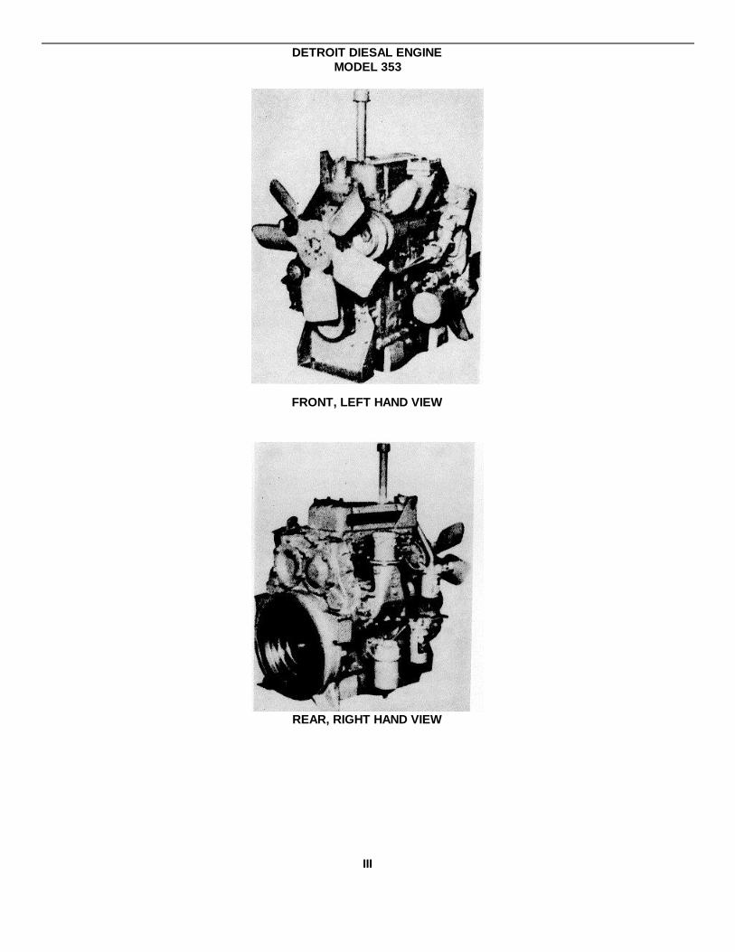
DETROIT DIESAL ENGINEMODEL 353
FRONT, LEFT HAND VIEW
REAR, RIGHT HAND VIEW
III
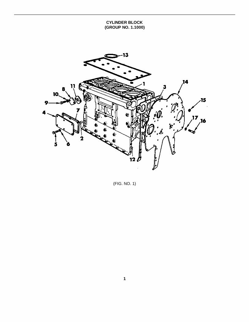
CYLINDER BLOCK(GROUP NO. 1.1000)
(FIG. NO. 1)
1

CYLINDER BLOCK(GROUP NO. 1.1000)
FIG/ITEM PART NO. DESCRIPTION QTY.
1-1 5196490 Block Assy. 13-1 5116142 Cap, Main Bearing 38-1 5198209 Bearing Set, Camshaft 13-2 5116199 Bolt, Main Bearing Cap 6* 5146437 Elbow, Air Box Drain Tee 1* 3231135 Tee, 1/4" Inv. Fl. 11-12 141346 Pin, 3/16" x 1/2" Dowel 41-2 5146900 Pin, 3/8" x 1-1/8" Dowel 4* 114981 Draincock, 1/8" 13-4 5145009 Plug, 1/8" Pipe 7* 5121182 Plug, 1/4" Pipe 1* 5150131 Plug, 7/16" Cup 2* 5121316 Plug, 5/8" x 13/32" 21-14 5121366 Plate Assy. 11-15 5121459 Nut, Plug 3/8" - 24 81-16 454813 Bolt, 3/8" - 16 x 7/8" 131-17 103321 Lockwasher, 3/8" AR1-3 5116354 Gasket 11-4 5116373 Cover 11-5 180120 Bolt, 3/8" - 16 x 3/4" 61-6 103321 Lockwasher, 3/8" 61-7 5116380 Gasket 11-8 5150023 Cover (Plain) 11-9 186618 Bolt, 5/16" - 18 x 5/8" 21-10 103320 Lockwasher, 5/16" 21-11 5116357 Gasket 1
* Not Shown
2
AIR BOX DRAINS(GROUP 1.1000A)
FIG/ITEM PART NO. DESCRIPTION QTY.
* 5132286 Tube 1* 137421 Elbow, 1/4" Inv. Fl. Tube 90 Deg. 1* 137397 Nut, 1/4" Inv. Fl. Tube 1
* Not Shown
CRANKSHAFT PULLEY BELT(GROUP NO. 1.3000D)
FIG/ITEM PART NO. DFSCRIPTIDN QTY.
* 5131395 Belt Set (2 Belts) (41.00" L., .500" W.) 1
* Not Shown
3
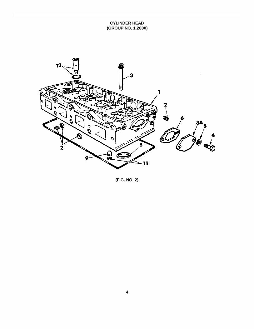
CYLINDER HEAD(GROUP NO. 1.2000)
(FIG. NO. 2)
4
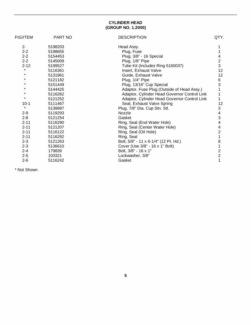
CYLINDER HEAD(GROUP NO. 1.2000)
FIG/ITEM PART NO DESCRIPTION QTY.
2- 5198203 Head Assy. 12-2 5198655 Plug, Fuse 12-2 5154453 Plug, 3/8" - 16 Special 42-2 5145009 Plug, 1/8" Pipe 22-12 5199527 Tube Kit (Includes Ring 5160037) 3* 5116361 Insert, Exhaust Valve 12* 5131961 Guide, Exhaust Valve 12* 5121182 Plug, 1/4" Pipe 6* 5151449 Plug, 13/16" Cup Special 3* 5144425 Adaptor, Fuse Plug (Outside of Head Assy.) 1* 5116262 Adaptor, Cylinder Head Governor Control Link 1* 5121252 Adaptor, Cylinder Head Governor Control Link 1
10-1 5111467 Seat, Exhaust Valve Spring 12* 5139997 Plug, 7/8" Dia. Cup Stn. Stl. 3
2-9 5119293 Nozzle 42-8 5121254 Gasket 32-11 5116290 Ring, Seal (End Water Hole) 42-11 5121207 Ring, Seal (Center Water Hole) 42-11 5116122 Ring, Seal (Oil Hole) 22-11 5116292 Ring, Seal 12-3 5121263 Bolt, 5/8" - 11 x 6-1/4" (12 Pt. Hd.) 82-3 5136610 Cover (Use 3/8" - 16 x 1" Bolt) 12-4 179839 Bolt, 3/8" - 16 x 1" 22-5 103321 Lockwasher, 3/8" 22-6 5116242 Gasket 1
* Not Shown
5

ENGINE LIFTER BRACKET(GROUP NO. 1.2000A)
FIG/ITEM PART NO. DESCRIPTION QTY.
* 5100428 Bracket (Front R.H.) 1* 5164294 Spacer, 1/8" Thick 2* 179839 Bolt, 3/8" - 16 x 1" AA Lock 3-1 5119379 Bracket (Also Fig 5 Item 2) (Rear) 1* 9409028 Bolt, 3/8" - 16 x 1" 2* 103341 Washer, 318" Flat 2* 103321 Washer, 3/8" Lock 3
*Not Shown
6
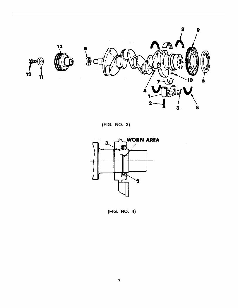
(FIG. NO. 3)
(FIG. NO. 4)
7
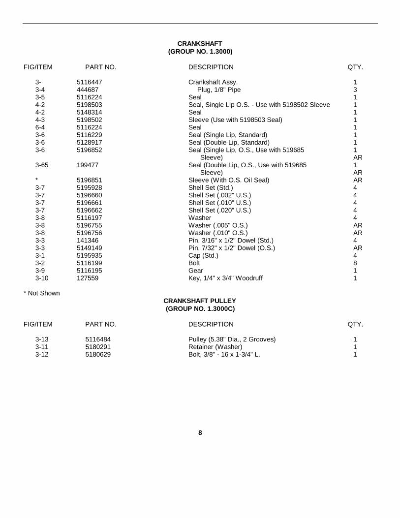
CRANKSHAFT(GROUP NO. 1.3000)
FIG/ITEM PART NO. DESCRIPTION QTY.
3- 5116447 Crankshaft Assy. 13-4 444687 Plug, 1/8" Pipe 33-5 5116224 Seal 14-2 5198503 Seal, Single Lip O.S. - Use with 5198502 Sleeve 14-2 5148314 Seal 14-3 5198502 Sleeve (Use with 5198503 Seal) 16-4 5116224 Seal 13-6 5116229 Seal (Single Lip, Standard) 13-6 5128917 Seal (Double Lip, Standard) 13-6 5196852 Seal (Single Lip, O.S., Use with 519685 1
Sleeve) AR3-65 199477 Seal (Double Lip, O.S., Use with 519685 1
Sleeve) AR* 5196851 Sleeve (With O.S. Oil Seal) AR3-7 5195928 Shell Set (Std.) 43-7 5196660 Shell Set (.002" U.S.) 43-7 5196661 Shell Set (.010" U.S.) 43-7 5196662 Shell Set (.020" U.S.) 43-8 5116197 Washer 43-8 5196755 Washer (.005" O.S.) AR3-8 5196756 Washer (.010" O.S.) AR3-3 141346 Pin, 3/16" x 1/2" Dowel (Std.) 43-3 5149149 Pin, 7/32" x 1/2" Dowel (O.S.) AR3-1 5195935 Cap (Std.) 43-2 5116199 Bolt 83-9 5116195 Gear 13-10 127559 Key, 1/4" x 3/4" Woodruff 1
* Not ShownCRANKSHAFT PULLEY(GROUP NO. 1.3000C)
FIG/ITEM PART NO. DESCRIPTION QTY.
3-13 5116484 Pulley (5.38" Dia., 2 Grooves) 13-11 5180291 Retainer (Washer) 13-12 5180629 Bolt, 3/8" - 16 x 1-3/4" L. 1
8

CRANKSHAFT FRONT COVER(GROUP NO. 1.3000A)
(FIG. NO. 5)
9
(FIG. NO. 5)

CRANKSHAFT FRONT COVER(GROUP NO. 1.3000A)
FIG/ITEM PART NO. DESCRIPTION QTY.
5- 5101347 Cover Assy., Engine Front Upper 1* 5146900 Pin, 3/8" x 1-1/8" Dowel 2
5-1 186622 Bolt, 3/8" - 16 x 1-1/4" 95-1 179844 Bolt, 3/8" - 16 x 1-5/8" 4* 9414322 Washer, 3/8" I.D. x .744 O.D. x .63 Thick 13
5-2 103321 Lockwasher, 3/8" 136- 5197415 Cover Assy., Engine Front Lower 1* 5145009 Plug, 1/8 Pipe 1* 5146648 Plug, 1/2 Pipe 7
6-1 186282 Bolt, 3/8" - 16 x 3-1/4" 76-2 103321 Lockwasher, 3/8" 75-3 5121082 Gasket, Upper 16-3 5116386 Gasket, Lower 16-4 5116224 Seal 1
* Not Shown
10

FLYWHEEL HOUSING (SAE #3)(GROUP NO. 1.5000A)
(FIG. NO. 7)
11

FLYWHEEL(GROUP NO. 1.4000A)
FIG/ITEM PART NO. DESCRIPTION QTY.
7- 5119495 Flywheel Assy. (Sae #3, Non-Chamfered)Includes 5116301 Gear 1
7-2 9412018 Bolt, Lock (2-1/4" L.) 67-1 5116301 Gear (Sae #3-126 Teeth) 17-15 5126671 Plate, Scuff 1
FLYWHEEL HOUSING (SAE #3)(GROUP NO. 1.5000A)
FIG/ITEM PART NO. DESCRIPTION QTY.
7-3 5132260 Housing, (Sae #3) (Also Fig 5 Item 3) 1* 5145011 Plug, 3/8" Pipe 1* 5145012 Plug, 1/2" Pipe 1
7-4 9409126 Bolt, 5/16 - 18 x 2-1/2 27-4 5101779 Bolt, 3/8" - 16 x 7/8" 17-4 9414215 Bolt, 3/8 - 16 x 2-1/2 47-4 427588 Bolt, 3/8" - 16 x 2-1/2 67-4 5170489 Bolt, 3/8 - 24 x 3 9-16 Lock 37-5 103321 Lockwasher, 3/8" AR7-16 5123802 Shim, Flywheel (Hsg. to End Plate) 17-6 5121334 Gasket 17-7 5122281 Cover 27-8 179857 Bolt, 7/16" - 14 x 7/8" 27-8 122408 Bolt, 1/2" - 13 x l" 8* 5150568 Washer, (7/16" Copper) 2
7-9 103323 Lockwasher, 1/2" 87-10 5117061 Gasket 27-11 5116411 Cover 27-12 186625 Bolt, 5/16" - 18 x 7/8" 47-13 103320 Lockwasher, 5/16" 47-14 5116391 Gasket 2* 5130995 Gasket 1
* Not Shown
12
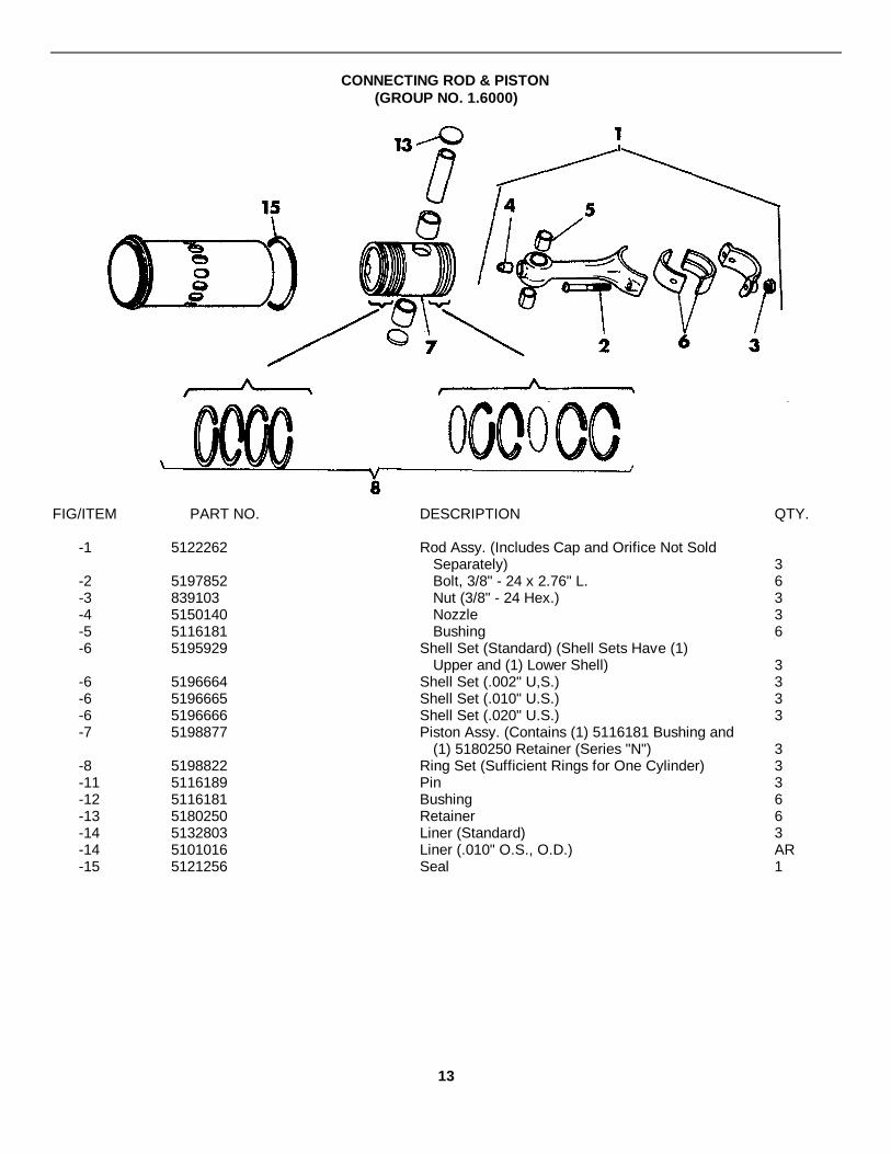
CONNECTING ROD & PISTON(GROUP NO. 1.6000)
FIG/ITEM PART NO. DESCRIPTION QTY.
-1 5122262 Rod Assy. (Includes Cap and Orifice Not SoldSeparately) 3
-2 5197852 Bolt, 3/8" - 24 x 2.76" L. 6-3 839103 Nut (3/8" - 24 Hex.) 3-4 5150140 Nozzle 3-5 5116181 Bushing 6-6 5195929 Shell Set (Standard) (Shell Sets Have (1)
Upper and (1) Lower Shell) 3-6 5196664 Shell Set (.002" U,S.) 3-6 5196665 Shell Set (.010" U.S.) 3-6 5196666 Shell Set (.020" U.S.) 3-7 5198877 Piston Assy. (Contains (1) 5116181 Bushing and
(1) 5180250 Retainer (Series "N") 3-8 5198822 Ring Set (Sufficient Rings for One Cylinder) 3-11 5116189 Pin 3-12 5116181 Bushing 6-13 5180250 Retainer 6-14 5132803 Liner (Standard) 3-14 5101016 Liner (.010" O.S., O.D.) AR-15 5121256 Seal 1
13

CAMSHAFT & GEAR TRAIN(GROUP NO. 1.7000)
(FIG. NO. 8)
(FIG. NO. 9)
14

CAMSHAFT & GEAR TRAIN(GROUP NO. 1.7000)
FIG/ITEM PART NO. DESCRIPTION QTY.
8-2 5126929 Camshaft Assy. 18-3 5151277 Plug (1/2" Drive) 28-1 5198209 Bearing Set Std. 18-1 5198980 Bearing Set (Std. I.D., .010" O.S. O.D.) AR8-1 5198470 Bearing Set (.010" U.S., I.D., Std. O.D.) AR8-1 5198471 Bearing Set (.020" U.S., I.D., Std. O.D.) AR8-4 3116198 Washer 28-5 9409028 Bolt, 3/8" - 16 x 1" 48-6 5106223 Seal, Oil (Front) 28-7 5134388 Slinger 28-8 5121071 Spacer 28-9 5121073 Shaft 18-10 5121108 Pulley 28-11 218217 Key, 3/16 x 5/8" Woodruff 28-12 5150087 Nut 28-13 5119277 Weight 28-14 9409028 Bolt, 3/8" - 16 x 1" Lock 48-15 5133387 Gear (R.H. Helix) 18-16 5133388 Gear (L.H. Helix) 18-17 218217 Key, 3/16" x 5/8" Woodruff 28-18 5150087 Nut 28-19 5121077 Spacer 18-20 5172734 Retainer 28-21 181360 Bolt, 3/8" - 24 x 3/4" 48-22 103321 Lockwasher, 3/8" 49- 5135227 Gear Assy., Idler 19-1 5196793 Bearing 19-2 5132504 Washer (Thrust) 29-3 5124458 Hub 19-4 5157244 Bolt 1
15
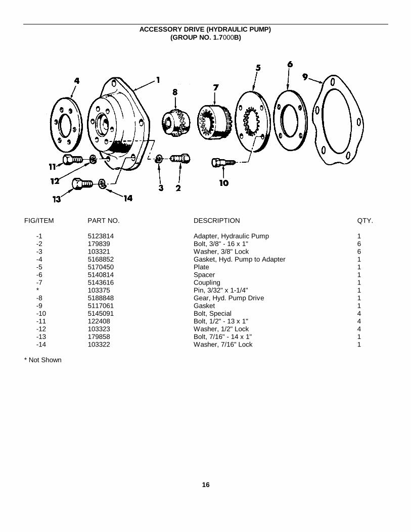
ACCESSORY DRIVE (HYDRAULIC PUMP)(GROUP NO. 1.7000B)
FIG/ITEM PART NO. DESCRIPTION QTY.
-1 5123814 Adapter, Hydraulic Pump 1-2 179839 Bolt, 3/8" - 16 x 1" 6-3 103321 Washer, 3/8" Lock 6-4 5168852 Gasket, Hyd. Pump to Adapter 1-5 5170450 Plate 1-6 5140814 Spacer 1-7 5143616 Coupling 1* 103375 Pin, 3/32" x 1-1/4" 1-8 5188848 Gear, Hyd. Pump Drive 1-9 5117061 Gasket 1-10 5145091 Bolt, Special 4-11 122408 Bolt, 1/2" - 13 x 1" 4-12 103323 Washer, 1/2" Lock 4-13 179858 Bolt, 7/16" - 14 x 1" 1-14 103322 Washer, 7/16" Lock 1
* Not Shown
16
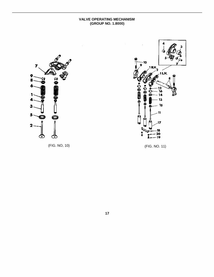
VALVE OPERATING MECHANISM(GROUP NO. 1.8000)
(FIG. NO, 10) (FIG. NO. 11)
17
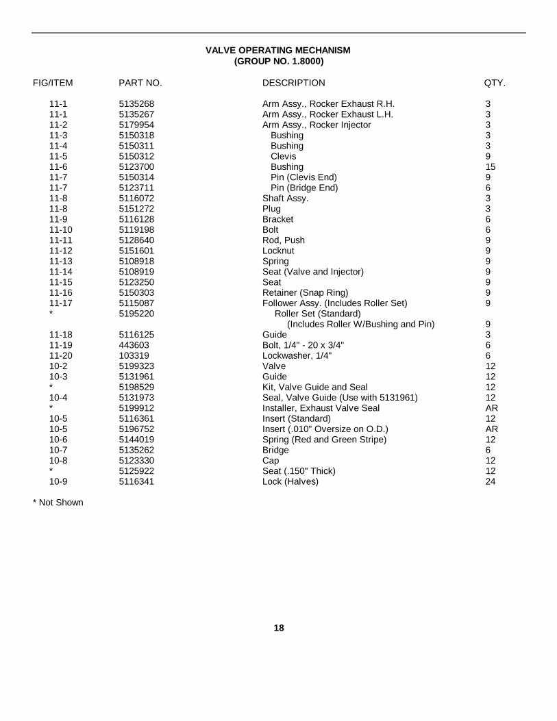
VALVE OPERATING MECHANISM(GROUP NO. 1.8000)
FIG/ITEM PART NO. DESCRIPTION QTY.
11-1 5135268 Arm Assy., Rocker Exhaust R.H. 311-1 5135267 Arm Assy., Rocker Exhaust L.H. 311-2 5179954 Arm Assy., Rocker Injector 311-3 5150318 Bushing 311-4 5150311 Bushing 311-5 5150312 Clevis 911-6 5123700 Bushing 1511-7 5150314 Pin (Clevis End) 911-7 5123711 Pin (Bridge End) 611-8 5116072 Shaft Assy. 311-8 5151272 Plug 311-9 5116128 Bracket 611-10 5119198 Bolt 611-11 5128640 Rod, Push 911-12 5151601 Locknut 911-13 5108918 Spring 911-14 5108919 Seat (Valve and Injector) 911-15 5123250 Seat 911-16 5150303 Retainer (Snap Ring) 911-17 5115087 Follower Assy. (Includes Roller Set) 9* 5195220 Roller Set (Standard)
(Includes Roller W/Bushing and Pin) 911-18 5116125 Guide 311-19 443603 Bolt, 1/4" - 20 x 3/4" 611-20 103319 Lockwasher, 1/4" 610-2 5199323 Valve 1210-3 5131961 Guide 12* 5198529 Kit, Valve Guide and Seal 1210-4 5131973 Seal, Valve Guide (Use with 5131961) 12* 5199912 Installer, Exhaust Valve Seal AR10-5 5116361 Insert (Standard) 1210-5 5196752 Insert (.010" Oversize on O.D.) AR10-6 5144019 Spring (Red and Green Stripe) 1210-7 5135262 Bridge 610-8 5123330 Cap 12* 5125922 Seat (.150" Thick) 1210-9 5116341 Lock (Halves) 24
* Not Shown
18
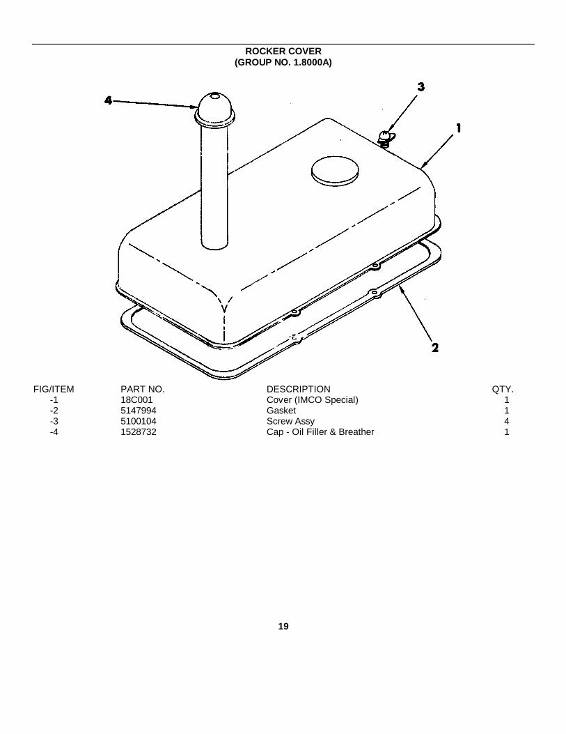
ROCKER COVER(GROUP NO. 1.8000A)
FIG/ITEM PART NO. DESCRIPTION QTY.-1 18C001 Cover (IMCO Special) 1-2 5147994 Gasket 1-3 5100104 Screw Assy 4-4 1528732 Cap - Oil Filler & Breather 1
19
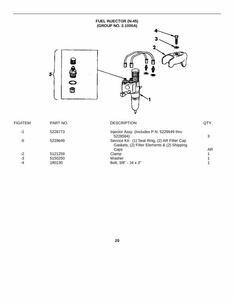
FUEL INJECTOR (N-45)(GROUP NO. 2.1000A)
FIG/ITEM PART NO. DESCRIPTION QTY.
-1 5228773 Injector Assy. (Includes P.N. 5229649 thru5228594) 3
-5 5229649 Service Kit: (1) Seal Ring, (2) AR Filter CapGaskets, (2) Filter Elements & (2) ShippingCaps AR
-2 5121259 Clamp 1-3 5150250 Washer 1-4 180130 Bolt, 3/8" - 16 x 2" 1
20

FUEL PUMP(GROUP NO. 2.2000)
FIG/ITEM PART NO. DESCRIPTION QTY.-1 5146341 Pump Assy. No Serviced; Use Part No. 5199560 1-2 5146337 Body 1-3 141195 Pin, 1/4" x 5/8" Dowel 2-4 5134560 Cover 1-5 3719219 Bolt, i/4" - 20 x 3/4" (With Lockwasher) 8-6 5230007 Seal 2-7 5174975 Gear 1-8 147481 Ball, 1/8" Dia. Steel 1-9 5181747 Shaft Assy. (Includes Gear) 1-10 5181746 Shaft Assy. (Includes Gear and Ball) 1-11 5174973 Valve 1-12 103709 Pin, 5/32" x 1" Straight 1-13 5184530 Spring 1-14 5174971 Plug 1-15 5161003 Gasket 1-16 5131685 Bolt, 5/16" - 18 x 3/4" (With Nyloc Insert) 3
5195078 Overhaul Kit, Fuel Pump (Includes Items 17, 6,8, 10, 9, 11, 12, 13, 15 AR
-17 5150193 Gasket 1-18 5154216 Coupling 1
21

FUEL FILTER(GROUP NO. 2.3000A)
(FIG. NO. 12)
(FIG. NO. 13)
22
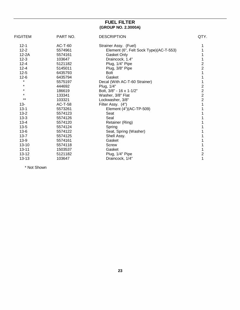
FUEL FILTER(GROUP NO. 2.3000A)
FIG/ITEM PART NO. DESCRIPTION QTY.
12-1 AC-T-60 Strainer Assy. (Fuel) 112-2 5574961 Element (6", Felt Sock Type)(AC-T-553) 112-2A 5574161 Gasket Only 112-3 103647 Draincock, 1.4" 112-4 5121182 Plug, 1/4" Pipe 212-4 5145011 Plug, 3/8" Pipe 212-5 6435793 Bolt 112-6 6435794 Gasket 1
* 5575197 Decal (With AC-T-60 Strainer) 1* 444692 Plug, 1/4" 2* 186619 Bolt, 3/8" - 16 x 1-1/2" 2* 133341 Washer, 3/8" Flat 2** 103321 Lockwasher, 3/8" 2
13- AC-T-58 Filter Assy. (4") 113-1 5573261 Element (4")(AC-TP-509) 113-2 5574123 Seat 113-3 5574126 Seal 113-4 5574120 Retainer (Ring) 113-5 5574124 Spring 113-6 5574122 Seat, Spring (Washer) 113-7 5574125 Shell Assy. 113-9 5574161 Gasket 113-10 5574118 Screw 113-11 1503537 Gasket 113-12 5121182 Plug, 1/4" Pipe 213-13 103647 Draincock, 1/4" 1
* Not Shown
23

(FIG. NO. 14)
24
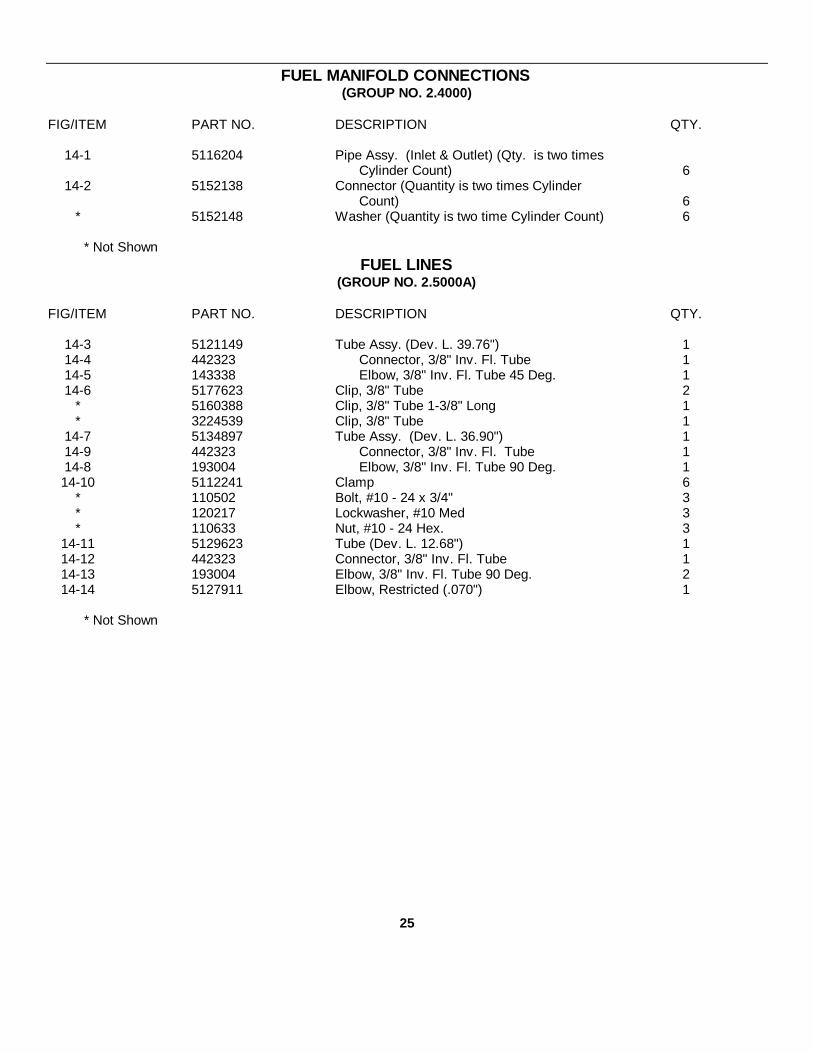
FUEL MANIFOLD CONNECTIONS(GROUP NO. 2.4000)
FIG/ITEM PART NO. DESCRIPTION QTY.
14-1 5116204 Pipe Assy. (Inlet & Outlet) (Qty. is two timesCylinder Count) 6
14-2 5152138 Connector (Quantity is two times CylinderCount) 6
* 5152148 Washer (Quantity is two time Cylinder Count) 6
* Not ShownFUEL LINES
(GROUP NO. 2.5000A)
FIG/ITEM PART NO. DESCRIPTION QTY.
14-3 5121149 Tube Assy. (Dev. L. 39.76") 114-4 442323 Connector, 3/8" Inv. Fl. Tube 114-5 143338 Elbow, 3/8" Inv. Fl. Tube 45 Deg. 114-6 5177623 Clip, 3/8" Tube 2
* 5160388 Clip, 3/8" Tube 1-3/8" Long 1* 3224539 Clip, 3/8" Tube 1
14-7 5134897 Tube Assy. (Dev. L. 36.90") 114-9 442323 Connector, 3/8" Inv. Fl. Tube 114-8 193004 Elbow, 3/8" Inv. Fl. Tube 90 Deg. 114-10 5112241 Clamp 6
* 110502 Bolt, #10 - 24 x 3/4" 3* 120217 Lockwasher, #10 Med 3* 110633 Nut, #10 - 24 Hex. 3
14-11 5129623 Tube (Dev. L. 12.68") 114-12 442323 Connector, 3/8" Inv. Fl. Tube 114-13 193004 Elbow, 3/8" Inv. Fl. Tube 90 Deg. 214-14 5127911 Elbow, Restricted (.070") 1
* Not Shown
25
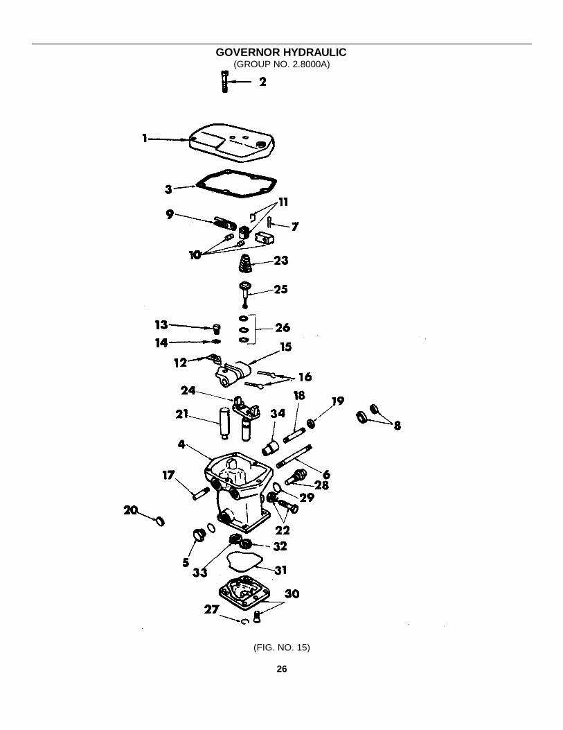
GOVERNOR HYDRAULIC(GROUP NO. 2.8000A)
(FIG. NO. 15)
26

GOVERNOR HYDRAULIC(GROUP NO. 2.8000A)
FIG/ITEM PART NO. DESCRIPTION QTY.
15 5136998 Governor Assembly 115-1 5199864 Cover 115-2 5197603 Screw #10 - 32 x 1" W/Lock Washer 315-3 3249110 Gasket' 1* 192484 Screw, 1/4" - 28 x 1-1/4" 1* 114492 Nut, 1/4" - 28 Hex (Thin) 115-4 5197105 Housing Assembly 115-4 444687 Plug 1/8" Pipe, Hex Soc. Hd. 115-5 5197052 Plug 1* 5197066 Gasket 115-6 5197080 Shaft 115-7 5197846 Pin, Roll 115-8 5197065 Seal 1* 5197059 Bushing 1-7/8" L. 1* 5197078 Bushing 1-1/2" L. 1* 5197060 Plug, Cup 115-9 5197013 Lever 115-9 5199196 Stop 115-9 5194069 Washer, 1/4" Copper 115-9 5194495 Nut 1/4" - 28 Hex Stop 15-10 5197015 Lever 115-10 5197016 Clip, Spring 115-11 5197014 Fork 115-12 5197046 Bracket, Droop (Includes Pin) 115-13 100659 Screw #10 - 32 x 3/8" 115-14 446142 Washer #10 Flat 115-15 5198332 Plate, Lever Support 115-16 137171 Pin, 3/32" x 1" Cotter 215-17 5197045 Shaft 1-11/32" L. 115-18 5197084 Shaft 2-3/8" L. 115-19 5197065 Seal 115-20 5197060 Plug, Cup 115-21 5197019 Piston 115-21 5197062 Pin, Piston 2-1/4" L. 115-22 3304053 Screw #10 - 32 x 1-1/4" 115-22 5194070 Washer #10 Copper 115-22 120614 Nut, #10 - 32 Hex 115-23 5198398 Spring 115-24 5198397 Ball Head Assembly 115-25 5197010 Plunger 115-26 5157328 Bearing 1
- Continued -
27
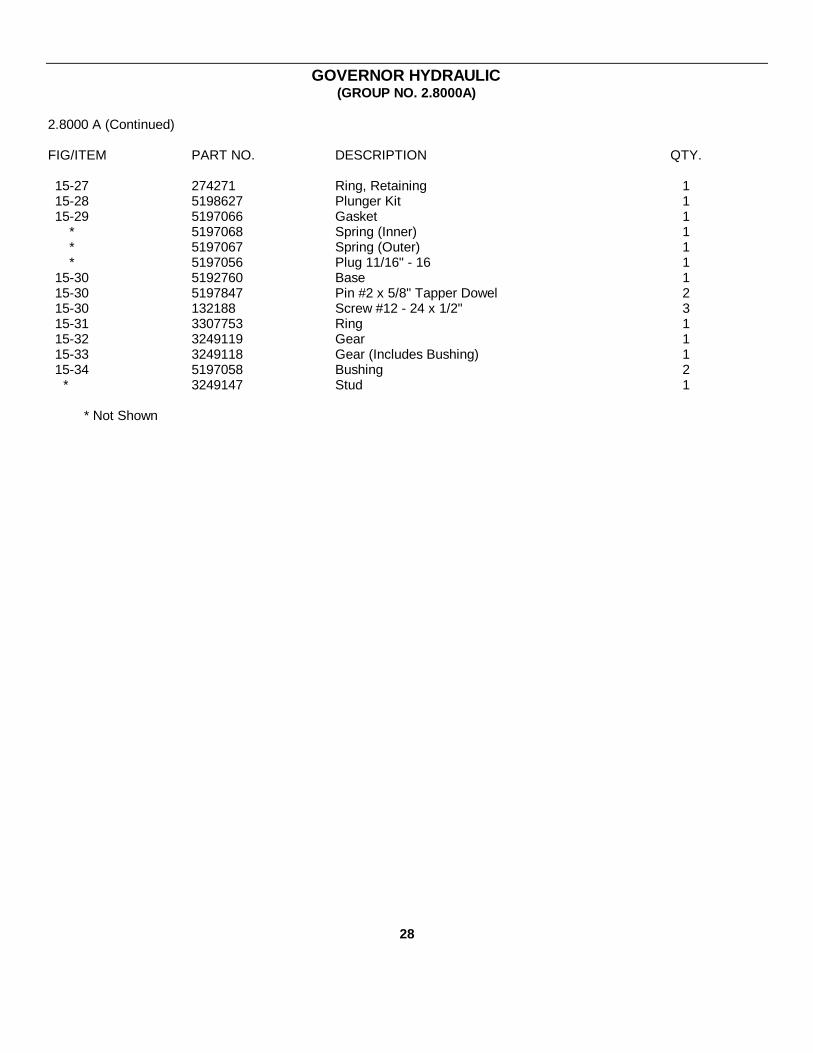
GOVERNOR HYDRAULIC(GROUP NO. 2.8000A)
2.8000 A (Continued)
FIG/ITEM PART NO. DESCRIPTION QTY.
15-27 274271 Ring, Retaining 115-28 5198627 Plunger Kit 115-29 5197066 Gasket 1
* 5197068 Spring (Inner) 1* 5197067 Spring (Outer) 1* 5197056 Plug 11/16" - 16 1
15-30 5192760 Base 115-30 5197847 Pin #2 x 5/8" Tapper Dowel 215-30 132188 Screw #12 - 24 x 1/2" 315-31 3307753 Ring 115-32 3249119 Gear 115-33 3249118 Gear (Includes Bushing) 115-34 5197058 Bushing 2
* 3249147 Stud 1
* Not Shown
28
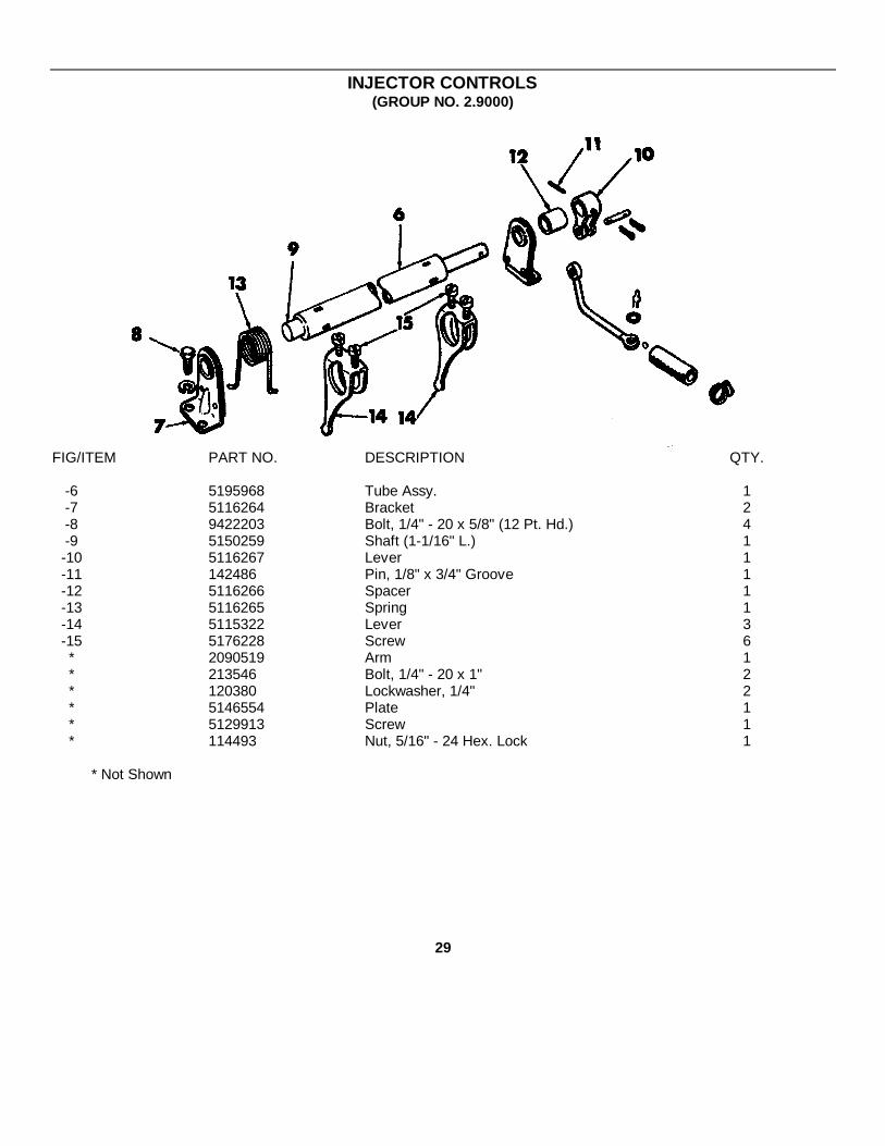
INJECTOR CONTROLS(GROUP NO. 2.9000)
FIG/ITEM PART NO. DESCRIPTION QTY.
-6 5195968 Tube Assy. 1-7 5116264 Bracket 2-8 9422203 Bolt, 1/4" - 20 x 5/8" (12 Pt. Hd.) 4-9 5150259 Shaft (1-1/16" L.) 1-10 5116267 Lever 1-11 142486 Pin, 1/8" x 3/4" Groove 1-12 5116266 Spacer 1-13 5116265 Spring 1-14 5115322 Lever 3-15 5176228 Screw 6* 2090519 Arm 1* 213546 Bolt, 1/4" - 20 x 1" 2* 120380 Lockwasher, 1/4" 2* 5146554 Plate 1* 5129913 Screw 1* 114493 Nut, 5/16" - 24 Hex. Lock 1
* Not Shown
29
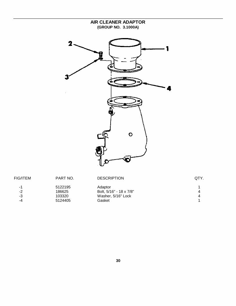
AIR CLEANER ADAPTOR(GROUP NO. 3.1000A)
FIG/ITEM PART NO. DESCRIPTION QTY.
-1 5122195 Adaptor 1-2 186625 Bolt, 5/16" - 18 x 7/8" 4-3 103320 Washer, 5/16" Lock 4-4 5124405 Gasket 1
30
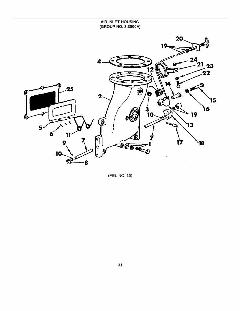
AIR INLET HOUSING(GROUP NO. 3.3000A)
(FIG. NO. 16)
31

AIR INLET HOUSING(GROUP NO. 3.3000A)
FIG/ITEM PART NO. DESCRIPTION QTY.
16 5121181 Housing Assembly 116-1 5157244 Bolt, 3/8" - 16 x 1-3/4" 416-1 179847 Bolt, 3/8" - 16 x 2" 116-1 179851 Bolt, 3/8" - 16 x 3" 116-1 103341 Washer, 3/8" Flat 616-1 103321 Washer, 3/8" Lock 616-2 5116383 Housing 116-3 5121182 Plug, 1/4" Pipe 116-4 5124405 Gasket 116-5 5116456 Valve 116-6 273436 Pin, 1/8" x 11/16" Roll 216-7 5116444 Shaft 116-8 103341 Washer, 3/8" Flat 116-9 273436 Pin, 1/8" x 11/16" Roll 116-10 5182977 Seal Ring 216-11 5111904 Spring (Valve, Internal) 116-12 5112787 Spring (Latch, R.H. Helix) 116-13 5114727 Latch 116-14 5143836 Bushing - Eccentric 116-15 179803 Bolt, 1/4" - 20 x 1-3/4" 116-16 120380 Washer, 1/4" Lock 116-17 5114974 Handle 116-18 5122623 Cam 1* 5146239 Wire, Assembly (90" L.) 116 -19 3796374 Guide 116-19 140855 Screw, #8 - 32 x 5/16" Hex, Socket 116-19 110730 Washer, 3/8" Lock 116-19 124925 Nut, 3/8" - 24 Hex 116-20 5186687 Plate, Instruction 116-21 3290569 Clip 116-22 123298 Bolt, 1/4" - 28 x 3/8" 116-23 120380 Washer, 1/4" Lock 116-24 121902 Nut, 1/4" - 28 Hex 116 -25 5196053 Screen 1
* Not Shown
32

BLOWER(GROUP NO. 3.4000)
(FIG. NO. 17)
33

BLOWER(GROUP NO. 3.4000)
FIG/ITEM PART NO. DESCRIPTION QTY.
17- 5139305 Blower Asm. 117-1 5119391 Housing (Includes Pins) 117-2 141242 Pin, 3/8" x 7/8" Dowel 417-3 5139297 Rotor Assy. 217-4 5134179 Plate 117-5 5116170 Spacer 317-6 9409062 Bolt, 1/4" - 20 x 1" 317-7 5127077 Washer, 25/64 I.D. 217-8 9409034 Bolt, 3/8" - 24 x 7/8" 217-9 5119194 Gear (R.H. Helix) 117-10 5119195 Gear (L.H. Helix) 1* 9409018 Bolt, 5/16" - 24 x 7/8" 2* 5121403 Washer, 21/64" x 1" x 3/16" 217-12 5116164 Shim (.002") AR17-12 5116165 Shim (.003") AR17-12 5116166 Shim (.004") AR17-12 5116167 Shim (.005") AR17-13 5116168 Spacer 217-14 5134914 Plate, Front 117-15 5139299 Plate, Rear 117-28 5145009 Plug, 1/8" Pipe 2* 117297 Screw, 5/16" - 18 x 1-3/4" Fil. Hd. 417-17 5142266 Seal (Lip Type) 417-18 9433110 Bolt, 7/16 - 14 x 6-11/16" 4* 5121464 Bolt (10-3/16" L.) 217-20 5116150 Bolt (10-11/16" L.) 417-21 5131913 Washer (7/16") (Flat) 4* 5198041 Blower Installation Kit AR* 5198684 Repair Kit Not Serviced, Use 5198683 Kit AR17-22 5119433 Gasket (To End Plate) 117-23 5116295 Gasket (To Block) 117-24 5119429 Cover 117-25 5119394 Plate, Reinforcement (Large) 217-26 5119395 Plate, Reinforcement (Small) 217-27 5119433 Gasket 1
* Not Shown
34

(FIG. NO. 18)
35
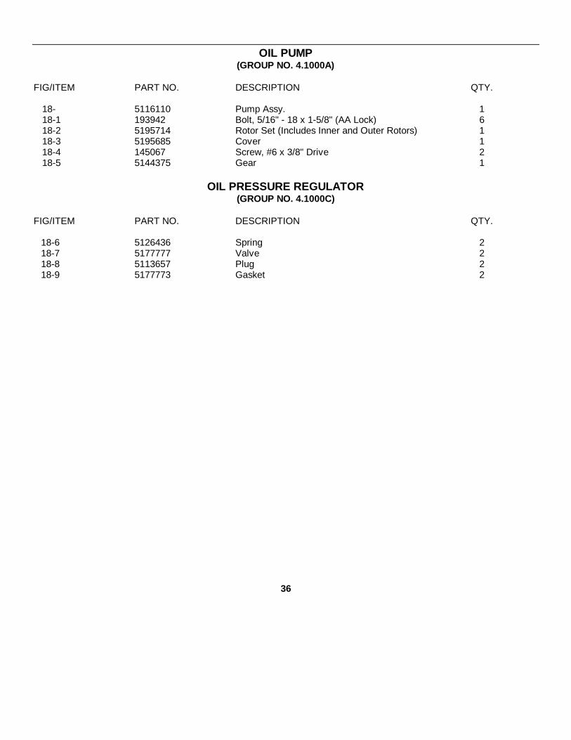
OIL PUMP(GROUP NO. 4.1000A)
FIG/ITEM PART NO. DESCRIPTION QTY.
18- 5116110 Pump Assy. 118-1 193942 Bolt, 5/16" - 18 x 1-5/8" (AA Lock) 618-2 5195714 Rotor Set (Includes Inner and Outer Rotors) 118-3 5195685 Cover 118-4 145067 Screw, #6 x 3/8" Drive 218-5 5144375 Gear 1
OIL PRESSURE REGULATOR(GROUP NO. 4.1000C)
FIG/ITEM PART NO. DESCRIPTION QTY.
18-6 5126436 Spring 218-7 5177777 Valve 218-8 5113657 Plug 218-9 5177773 Gasket 2
36

OIL DISTRIBUTION SYSTEM(GROUP NO. 4.1000B)
FIG/ITEM PART NO. DESCRIPTION QTY.
-1 5126211 Pipe (Includes Support 5125947Not Serviced Separately) 1
-2 5119425 Flange 1-3 5127175 Seal Ring 1-4 179816 Bolt, 5/16" - 18 x 3/4" 4-5 103320 Lockwasher, 5/16" 4-6 5126456 Screen Assy. 1-7 5152385 Screen 1-8 274558 Nut, 5/16" - 24 Hex, Lock 2
37

OIL FILTER(GROUP NO. 4.2000A)
(FIG. NO. 19)
38

OIL FILTER(GROUP NO. 4.2000A)
FIG/ITEM PART NO. DESCRIPTION QTY.
19- 5134393 Filter Assy. Not Serviced; For Replacement 1Use Assembly (5100 757) 1
19-1 5574978 Element (6") (AC-PF-147) 119-2 5574906 Shell (Includes Plug) 119-3 5570480 Plug 119-4 5100818 Adapter 119-5 4544557 Plug, 1/4" Pipe 119-6 5573711 Gasket 119-7 5187308 Spring 119-8 5187309 Retainer 1* 5120602 Retainer (Snap Ring) 119-9 122366 Nut, 5/8" - 18 Hex. 119-10 5187310 Gasket, Retainer 119-10 6437298 Gasket 119-11 5154538 Washer 119-12 5130740 Stud 1* 5198303 Valve Kit 119-13 5133431 Valve 119-14 5134477 Spring 1* 5134456 Retainer 1* 450865 Screw Rnd. Hd. 1* 5134920 Gasket 119-17 5575213 Decal 119-18 454906 Bolt, 3/8" - 16 x 1-1/2" 4* 103341 Washer, 3/8" Flat 419-19 103321 Lockwasher, 3/8" 419-20 5121205 Gasket 1
* Not Shown
39
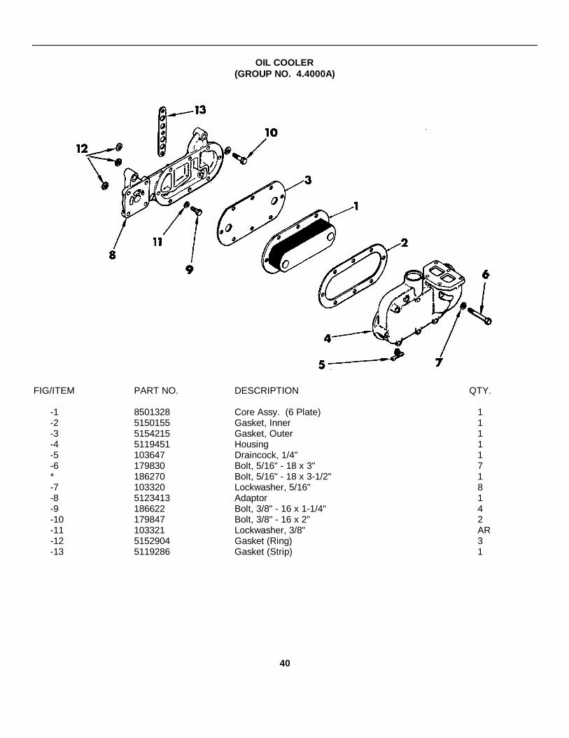
OIL COOLER(GROUP NO. 4.4000A)
FIG/ITEM PART NO. DESCRIPTION QTY.
-1 8501328 Core Assy. (6 Plate) 1-2 5150155 Gasket, Inner 1-3 5154215 Gasket, Outer 1-4 5119451 Housing 1-5 103647 Draincock, 1/4" 1-6 179830 Bolt, 5/16" - 18 x 3" 7* 186270 Bolt, 5/16" - 18 x 3-1/2" 1-7 103320 Lockwasher, 5/16" 8-8 5123413 Adaptor 1-9 186622 Bolt, 3/8" - 16 x 1-1/4" 4-10 179847 Bolt, 3/8" - 16 x 2" 2-11 103321 Lockwasher, 3/8" AR-12 5152904 Gasket (Ring) 3-13 5119286 Gasket (Strip) 1
40
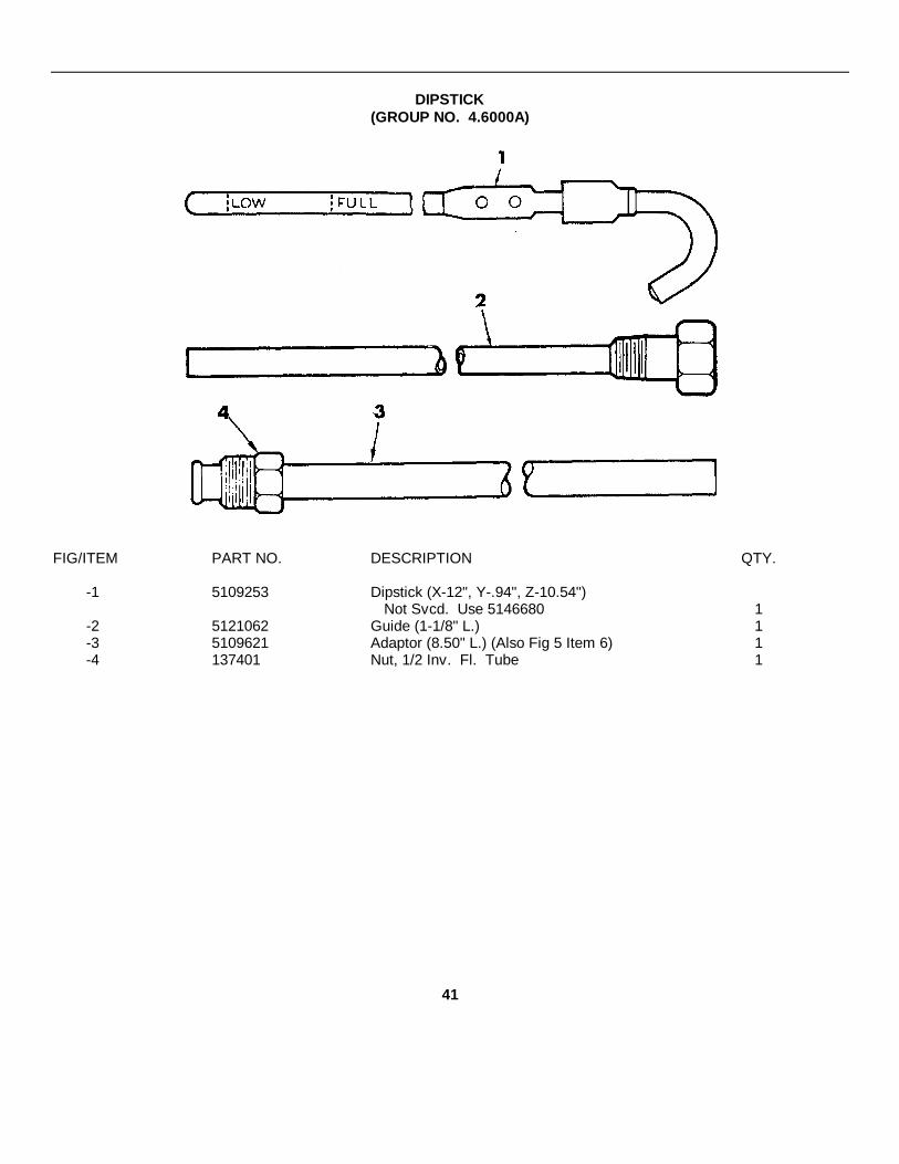
DIPSTICK(GROUP NO. 4.6000A)
FIG/ITEM PART NO. DESCRIPTION QTY.
-1 5109253 Dipstick (X-12", Y-.94", Z-10.54")Not Svcd. Use 5146680 1
-2 5121062 Guide (1-1/8" L.) 1-3 5109621 Adaptor (8.50" L.) (Also Fig 5 Item 6) 1-4 137401 Nut, 1/2 Inv. Fl. Tube 1
41

OIL PAN(GROUP NO. 4.7000A)
FIG/ITEM PART NO. DESCRIPTION QTY.
-1 5146360 Pan 1-2 5148437 Bolt, 5/16" - 18 x 1" 20-3 5116256 Gasket 1* 5145012 Plug, 1/2" - 14 Hex. Skt. 3-4 5142549 Plug, 3/4" Pipe Sq. Skt. 1
* Not Shown
42
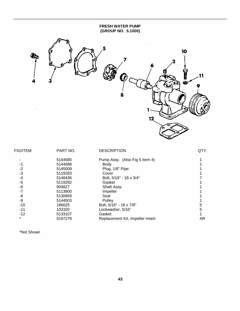
FRESH WATER PUMP(GROUP NO. 5.1000)
FIG/ITEM PART NO. DESCRIPTION QTY.
- 5144685 Pump Assy. (Also Fig 5 Item 4) 1-1 5144688 Body 1-2 5145009 Plug, 1/8" Pipe 1-3 5119283 Cover 1-4 5148436 Bolt, 5/16" - 18 x 3/4" 7-5 5119282 Gasket 1-6 904827 Shaft Assy. 1-7 5113800 Impeller 1-8 5130959 Seal 1-9 5144503 Pulley 1-10 186625 Bolt, 5/16" - 18 x 7/8" 5-11 103320 Lockwasher, 5/16" 5-12 5133107 Gasket 1* 5197279 Replacement Kit, Impeller Insert AR
*Not Shown
43
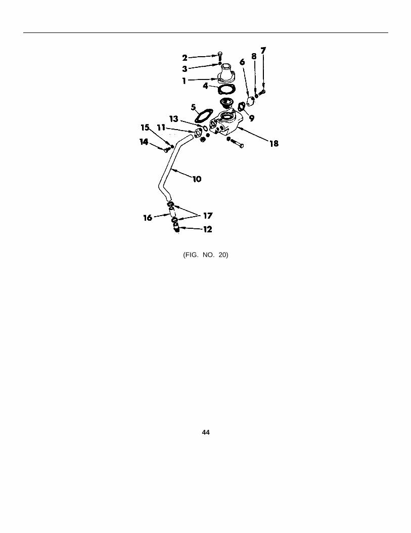
(FIG. NO. 20)
44

WATER OUTLET ELBOW(GROUP NO. 5.2000A)
FIG/ITEM PART NO. DESCRIPTION QTY.
20-1 5116409 Flange, (2-1/2" L.) 120-2 186619 Bolt, 3/8" - 16 x 1-1/8" 220-3 103321 Lockwasher, 3/8" 220-4 5116092 Gasket 1
THERMOSTAT(GROUP NO. 5.2000B),
FIG/ITEM PART NO. DESCRIPTION QTY.
20- 33041379 Thermostat Assy. 120-18 5123247 Housing 1
* 5145014 Plug, 3/8" Pipe 2* 5115214 Plug, 1/2" Pipe 2* 108608 Bolt, 3/8" - 16 x 2-1/8" 2* 103321 Lockwasher, 3/8" AR
20-5 5116242 Gasket 120-6 5119426 Flange 120-7 186618 Bolt, 5/16" - 18 x 5/8" 220-8 103320 Lockwasher, 5/16" AR20-9 5128139 Gasket 1
* Not Shown
WATER BY-PASS TUBE(GROUP NO. 5.2000C)
FIG/ITEM PART NO, DESCRIPTION QTY.
20-10 5108944 Tube 120-11 5119425 Flange 120-12 5144702 Connector 120-13 5184301 Seal Ring 1
* 5142549 Plug, 3/4" Pipe 120-14 186625 Bolt, 5/16" - 18 x 7/8" 220-15 103320 Lockwasher, 5/16" 220-16 5169721 Hose, 7/8" I.D. x 1.74" L. Std. Length Hose;
Cut to Length Shown 120-17 5186840 Clamp, 1" Dia. Hose 2
* Not Shown
45
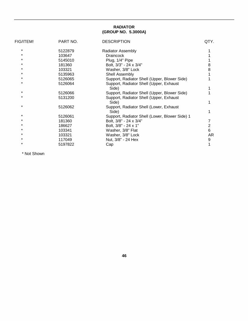
RADIATOR(GROUP NO. 5.3000A)
FIG/ITEM! PART NO. DESCRIPTION QTY.
* 5122879 Radiator Assembly 1* 103647 Draincock 1* 5145010 Plug, 1/4" Pipe 1* 181360 Bolt, 3/3" - 24 x 3/4" 8* 103321 Washer, 3/8" Lock 8* 5135963 Shell Assembly 1* 5126065 Support, Radiator Shell (Upper, Blower Side) 1* 5126064 Support, Radiator Shell (Upper, Exhaust
Side) 1* 5126066 Support, Radiator Shell (Upper, Blower Side) 1* 5131200 Support, Radiator Shell (Upper, Exhaust
Side) 1* 5126062 Support, Radiator Shell (Lower, Exhaust
Side) 1* 5126061 Support, Radiator Shell (Lower, Blower Side) 1* 181360 Bolt, 3/8" - 24 x 3/4" 7* 186627 Bolt, 3/8" - 24 x 1" 2* 103341 Washer, 3/8" Flat 6* 103321 Washer, 3/8" Lock AR* 117049 Nut, 3/8" - 24 Hex 9* 5197822 Cap 1
* Not Shown
46

WATER CONNECTIONS(GROUP NO. 5.3000B)
FIG/ITEM PART NO. DESCRIPTION QTY.
* 5119026 Elbow, Not Serviced, Use 5138275 Plus(2) 5145014. 1
* 179819 Bolt, 5/16" - 18 x 1-1/8" 2* 103320 Lockwasher, 5/16" 2* 5116357 Gasket 1* 5199777 Hose (17/8" I.D. x 4-3/4") Std. Length Hose,
Cut to Length Shown 1* 5186841 Clamp, 1-9/16" - 2-1/2" Dia. Hose 2
* Not Shown
47
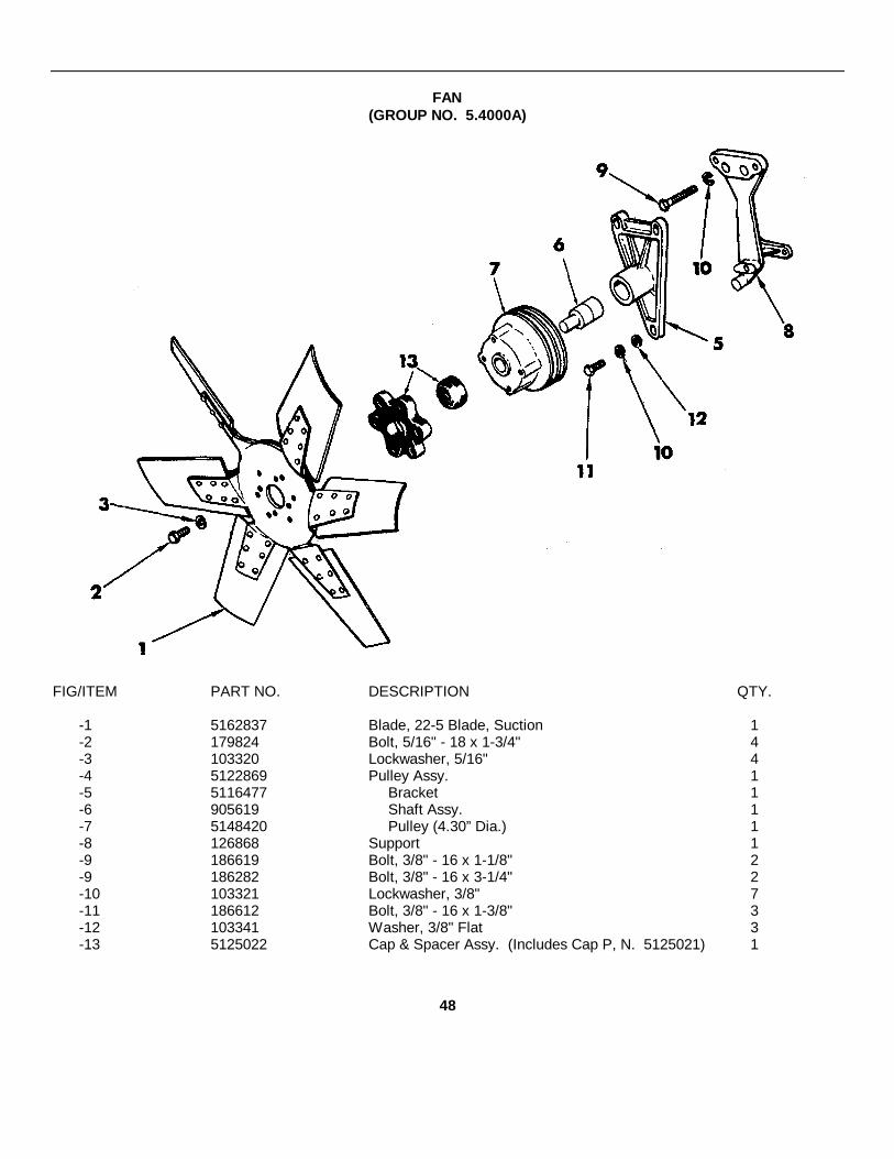
FAN(GROUP NO. 5.4000A)
FIG/ITEM PART NO. DESCRIPTION QTY.
-1 5162837 Blade, 22-5 Blade, Suction 1-2 179824 Bolt, 5/16" - 18 x 1-3/4" 4-3 103320 Lockwasher, 5/16" 4-4 5122869 Pulley Assy. 1-5 5116477 Bracket 1-6 905619 Shaft Assy. 1-7 5148420 Pulley (4.30” Dia.) 1-8 126868 Support 1-9 186619 Bolt, 3/8" - 16 x 1-1/8" 2-9 186282 Bolt, 3/8" - 16 x 3-1/4" 2-10 103321 Lockwasher, 3/8" 7-11 186612 Bolt, 3/8" - 16 x 1-3/8" 3-12 103341 Washer, 3/8" Flat 3-13 5125022 Cap & Spacer Assy. (Includes Cap P, N. 5125021) 1
48

(FIG. NO. 21)
49

EXHAUST MANIFOLD(GROUP NO. 6.1000A)
FIG/ITEM PART NO. DESCRIPTION OTY.
21-1 5130330 Manifold 121-2 113175 Plug, 1/8" Pipe 121-3 5188273 Washer (Dished, 1-1/4" O.D.) 421-4 127855 Nut, 7/16" - 20 421-5 5116205 Gasket 121-6 5112899 Stud, 7/16" x 2-3/32" L. 4
EXHAUST MUFFLER FLANGE(GROUP NO. 6.2000A)
FIG/ITEM PART NO. DESCRIPTION QTY.
* 51108632 Flange (Customer Furnished) 121-11 5108377 Gasket 1
* 103321 Lock Wash 3/8 4* 1145447 Nut 3/8" - 24 Hex (Brass) 4* 5109158 Stud 3/8 - 16-3/8 - 24 x 1-1/2" L. 4
* Not Shown
50
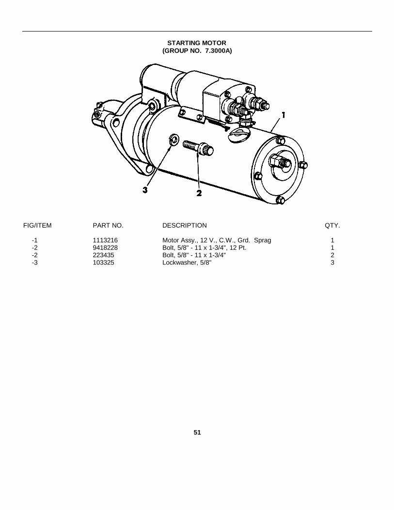
STARTING MOTOR(GROUP NO. 7.3000A)
FIG/ITEM PART NO. DESCRIPTION QTY.
-1 1113216 Motor Assy., 12 V., C.W., Grd. Sprag 1-2 9418228 Bolt, 5/8" - 11 x 1-3/4", 12 Pt. 1-2 223435 Bolt, 5/8" - 11 x 1-3/4" 2-3 103325 Lockwasher, 5/8" 3
51

ENGINE MOUNT(GROUP NO. 11.1000A)
FIG/ITEM PART NO. DESCRIPTION QTY.
-1 5123945 Support 1* 186283 Bolt, 3/8" - 16 x 3-1/2" 4* 454933 Bolt, 7/16" - 14 x 1-1/8" 4* 103321 Washer, 3/8" Lock 4* 103322 Washer, 7/16" Lock 4
* Not Shown
52

PART III. EQUIPMENT OPERATIONAND MAINTENANCE INSTRUCTIONS
PAVING MACHINE
SECTION 1
TABLE OF CONTENTS
Subject Page
Section 2 - General InformationInspection on arrival .................................................................................................................... 3Instructions for moving paver ...................................................................................................... 3Dimensions and specifications ............................................... ..................................................... 5 & 6Loading and unloading paver .......................................... ........................................................... 5Paver function and application .......................................... .......................................................... 7
Section 3 - Tractor and DrivesEngine data ............................................................... ................................................................. 9Paver instruments ....................................................................................................................... 9Engine controls ........................................................... ................................................................ 10Main clutch ........................................ ......................................................................................... 12 & 14Transmission........................................ ....................................................................................... 13 & 14Brakes ....................................................................................................................................... 15Feed clutches ............................................................................................................................. 15
Section 4 - Electrical SystemGenerator -120 Volt AC system ................................................................................................... 17Generator -12 Volt DC system .................................................................................................... 18, 21 & 22Main panel components ............................................................................................................. 19Trouble Shooting - general .......................................................................................................... 23Trouble Shooting - 12 VDC systems ........................................................................................... 23 - 26Trouble Shooting - 120 VDC systems .......................................................................................... 27Wiring Diagrams - paver systems .............................................................................................. 29 & 30
Section 5 - Hydraulic System.. ........................................................................................................ 31 - 46
Section 6 - Material Feed SystemHopper wings ............................................................................................................................... 47Feed clutches .............................................................. ............................................................... 47Slat conveyors and spreader screws .......................................... ................................................ 48Manual and automatic controlling................................................................................................. 50Hopper gate adjustment............................................................................................................... 51
(Continued on following page)
Page 1
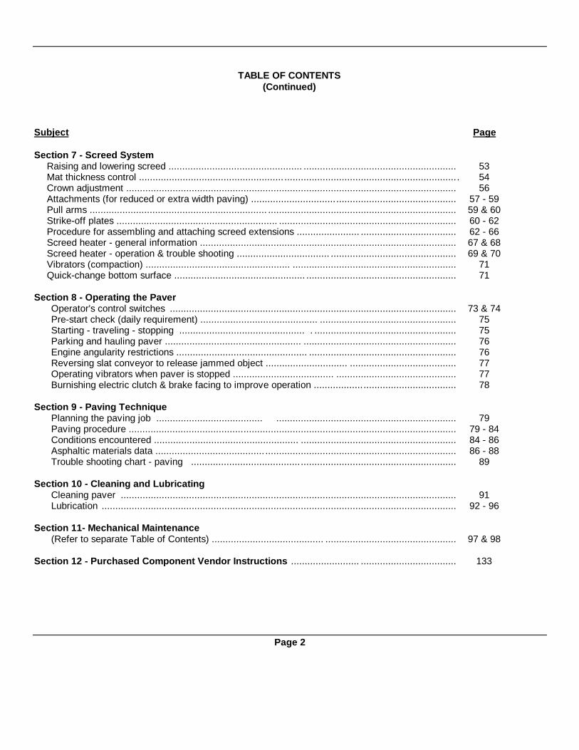
TABLE OF CONTENTS(Continued)
Subject Page
Section 7 - Screed SystemRaising and lowering screed ................................................. ........................................................ 53Mat thickness control ..................................................... ................................................................ 54Crown adjustment ......................................................................................................................... 56Attachments (for reduced or extra width paving) ........................................................................... 57 - 59Pull arms ................................................................. ..................................................................... 59 & 60Strike-off plates ........................................................... ................................................................. 60 - 62Procedure for assembling and attaching screed extensions ....................... ................................... 62 - 66Screed heater - general information .............................................................................................. 67 & 68Screed heater - operation & trouble shooting .................................. .............................................. 69 & 70Vibrators (compaction) ..................................................... ............................................................ 71Quick-change bottom surface ................................................ ....................................................... 71
Section 8 - Operating the PaverOperator's control switches ......................................................................................................... 73 & 74Pre-start check (daily requirement) ........................................... .................................................. 75Starting - traveling - stopping .............................................. . .................................................... 75Parking and hauling paver .................................................. ........................................................ 76Engine angularity restrictions ................................................ ...................................................... 76Reversing slat conveyor to release jammed object .............................. ....................................... 77Operating vibrators when paver is stopped ..................................... ............................................ 77Burnishing electric clutch & brake facing to improve operation .................................................... 78
Section 9 - Paving TechniquePlanning the paving job ....................................... .................................................................. 79Paving procedure ........................................................................................................................ 79 - 84Conditions encountered ..................................................... ......................................................... 84 - 86Asphaltic materials data ........................................ ...................................................................... 86 - 88Trouble shooting chart - paving ................................................................................................. 89
Section 10 - Cleaning and LubricatingCleaning paver ........................................................................................................................... 91Lubrication .................................................................................................................................. 92 - 96
Section 11- Mechanical Maintenance(Refer to separate Table of Contents) ......................................... ................................................ 97 & 98
Section 12 - Purchased Component Vendor Instructions ......................... ................................... 133
Page 2

SECTION IIGENERAL INFORMATION
Identification Of Paver ComponentsFigure 1
INSPECTION UPON ARRIVAL1. As soon as the paver arrives it should be
thoroughly inspected for visible damage.2. Check the freight bill or packing list against all
parts packed in boxes shipped with the paver.3. Install all parts which were removed for shipment.
Some of these will be found inside the paver tool box.(See Figure 1)
INSTRUCTIONS FOR MOVING PAVERExplicit instructions covering the proper procedure for
moving the paver under it's own power are printed insidethe protective cover for the operator's console. Theseinstructions should be studied before any attempt is madeto start the engine and move the paver in either direction. Paver Serial Number Location
Figure 2
Page 3
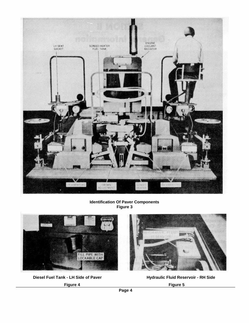
Identification Of Paver ComponentsFigure 3
Diesel Fuel Tank - LH Side of Paver Hydraulic Fluid Reservoir - RH Side
Figure 4 Figure 5Page 4

DIMENSIONS AND SPECIFICATIONSCapacities:Mat Width..........................................................................................................................6'to 10' standardMat Width......................................................................................................................... 10' to 20'optional(For paving widths over 20' - consult factory)Mat Thickness.................................................................................................................................... to 10"Paving Speeds............................................................................................................. 11 FPM to 132 FPMTravel Speed ....................................................................................................................... Up to 3.8 MPHHopper Capacity .............................................................................................................................10 TonsWeight:Standard width paver (diesel engine) . 24,000 lbs.Extensions to 20' paving widths.....................................................................................................2225 lbs.Overall Dimensions: (Also see page 8)Length ............................................................................................................................................... 16'-5"Width (without extension)................................................................................................................... 10'-3"Height (to top of engine)................................................................................................................... 8'-1½ /"Ground Clearance to Screws.............................................................................................................. 4 5/8"Supply Tank Capacities:Engine Fuel ................................................................................................................................ 33 gallonsHydraulic System Oil .................................................................................................................. 10 gallonsScreed Heater Fuel (Oil) .......................................................................................................... 12.5 gallons
Figure 6 - Correct Lifting Points (Four)LOADING AND UNLOADING PAVER
The self-propelled paver can be loaded or unloaded by constructing a ramp or by using a dock or a platform.CAUTION! Be sure all support methods used will safely carry the full weight of the paver. The Diesel driven unitweights 24,000 lbs.
If a crane with 30,000 lbs. lifting capacity is available it can be used to load or unload the paver. Attach liftingcables at the four points shown in Figure 6.
SHIPPING BRACE & FASTENER REMOVALImportant! Before attempting to move the paver either by hoisting or driving be sure all shipping blocks,
cables, braces, and other fasteners have been completely removed.CLEARANCE FOR UNLOADING & TRAVELThe clearance from ground level of the paver to the bottom of its spreader screws is 45/8". All loading and
unloading ramps must be built so that the spreader screws will not drag and be damaged at any point. In traveling, caremust be taken not to bring the screws into contact with any firm object.
IMPORTANT! Before attempting to start the paver engine and to move it under its own power, read andcomply with all instructions given under "Pre-Start Check" in Section 8 - Operation.
Instructions for moving the paver are also printed inside the protective cover of the operator's console.SCREED ELEVATION FOR UNLOADING AND TRAVEL(For explanation of the term "Screed" read following page.)
The screed must always be raised for unloading or travel. Normally it will be suspended by two safety cables forthis type of paver movement. (Refer to Screen Section 7 for details.) When the paver is to be loaded and transported alengthy distance, provide smooth wood blocks for three point support on the truck bed. Lower the screed to these blocks,located at each end and at the center. Important! Never rest the screed bottom on bolts, rivets, nails, etc. which couldscratch and gouge the bottom surface.TRAVEL SPEED
The paver has a top travel speed of approximately 3.8 MPH. It can be driven from one paving location to anotherwhen practical. If considerable traveling is done the track rollers should be lubricated properly at least twice daily. (SeeLubrication Instructions, Section 10.)
Page 5

MODEL BSF-400 ASPHALT PAVER DIMENSIONS
TOP VIEW-FIGURE 7
SIDE VIEW-FIGURE 8
Page 6

Figure 9. Material Flow Diagram
FUNCTION AND APPLICATIONThe Cedarapids crawler mounted paver is designed to lay a uniform high density mat of asphalt material on
highways, roadways, airport-runways, parking lots and driveways. It is cap able of performing jobs having strict controlspecifications and high production requirements. The paver will level and compact asphalt material up to 10 inches indepth, with mat widths varying from 6 to 20 feet. Mat depth and width variations are accomplished by adjustment of feedcontrols and by arrangement and adjustment of the finishing and compacting device called the "Screed."OPERATING PRINCIPLE
The uniformly mixed, hot asphalt material is dumped by truck loads onto the hopper of the paver at a rate suitablefor spreading and finishing. During this unloading process the paver contacts the rear wheels of the truck and pushes thevehicle ahead with it's own power as the paving progresses.
The hot material from the hopper is metered by two separate slat conveyors to the two spreading screws which areat the rear of the tractor unit and ahead of the screed. The feed of material may be either manually or automaticallyregulated to obtain a properly proportioned distribution. The attached "screed" assembly which is a full floating unit drawnby the tractor, "rides up" on the asphalt to the degree set on the adjustable controls and in so doing varies the thicknessand contour of the mat deposited beneath it. The screed controls can be adjusted either manually or automatically tocreate a new surface which is minus the undesirable irregularities of the old. The screed unit which performs the "ironing"job on the asphalt is equipped with electric vibrators which assist in the initial compaction and smoothing of the highdensity mat.
Final compaction of the newly laid asphalt mat is accomplished by separate rolling equipment according toestablished compaction specifications.
The paver screed can be fitted with special attachments for paving of highway shoulders which are not simpleextensions of the roadway. Numerous cut-off and beveling attachments meet the need for varying width and contourrequirements.The screed is equipped with an oil or gas fired heater which is operated prior to paving in order to bring the screedtemperature up to the temperature of the asphalt, so that no sticking and dragging will occur.
The raising and lowering of the full floating screed for either paving or travel is done hydraulically by toggle switchcontrol.
Page 7
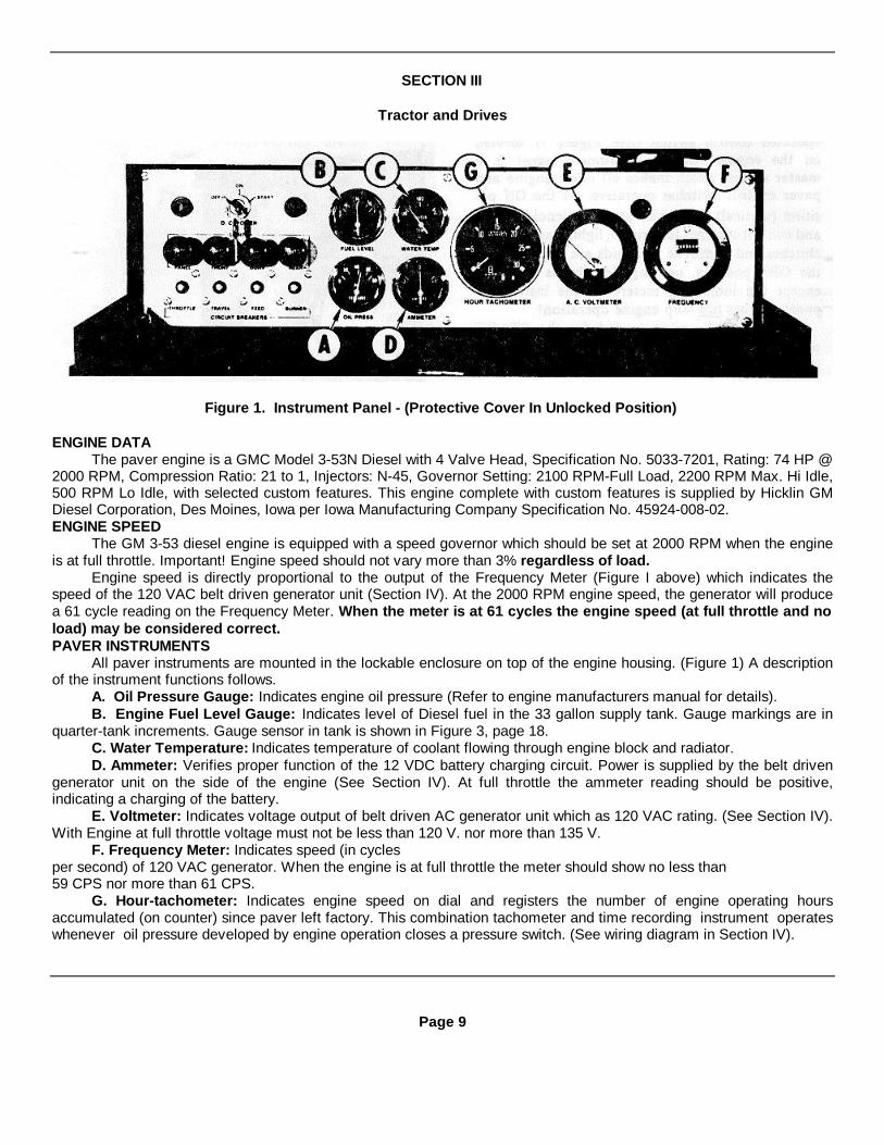
SECTION III
Tractor and Drives
Figure 1. Instrument Panel - (Protective Cover In Unlocked Position)
ENGINE DATAThe paver engine is a GMC Model 3-53N Diesel with 4 Valve Head, Specification No. 5033-7201, Rating: 74 HP @
2000 RPM, Compression Ratio: 21 to 1, Injectors: N-45, Governor Setting: 2100 RPM-Full Load, 2200 RPM Max. Hi Idle,500 RPM Lo Idle, with selected custom features. This engine complete with custom features is supplied by Hicklin GMDiesel Corporation, Des Moines, Iowa per Iowa Manufacturing Company Specification No. 45924-008-02.ENGINE SPEED
The GM 3-53 diesel engine is equipped with a speed governor which should be set at 2000 RPM when the engineis at full throttle. Important! Engine speed should not vary more than 3% regardless of load.
Engine speed is directly proportional to the output of the Frequency Meter (Figure I above) which indicates thespeed of the 120 VAC belt driven generator unit (Section IV). At the 2000 RPM engine speed, the generator will producea 61 cycle reading on the Frequency Meter. When the meter is at 61 cycles the engine speed (at full throttle and noload) may be considered correct.PAVER INSTRUMENTS
All paver instruments are mounted in the lockable enclosure on top of the engine housing. (Figure 1) A descriptionof the instrument functions follows.
A. Oil Pressure Gauge: Indicates engine oil pressure (Refer to engine manufacturers manual for details).B. Engine Fuel Level Gauge: Indicates level of Diesel fuel in the 33 gallon supply tank. Gauge markings are in
quarter-tank increments. Gauge sensor in tank is shown in Figure 3, page 18.C. Water Temperature: Indicates temperature of coolant flowing through engine block and radiator.D. Ammeter: Verifies proper function of the 12 VDC battery charging circuit. Power is supplied by the belt driven
generator unit on the side of the engine (See Section IV). At full throttle the ammeter reading should be positive,indicating a charging of the battery.
E. Voltmeter: Indicates voltage output of belt driven AC generator unit which as 120 VAC rating. (See Section IV).With Engine at full throttle voltage must not be less than 120 V. nor more than 135 V.
F. Frequency Meter: Indicates speed (in cyclesper second) of 120 VAC generator. When the engine is at full throttle the meter should show no less than59 CPS nor more than 61 CPS.
G. Hour-tachometer: Indicates engine speed on dial and registers the number of engine operating hoursaccumulated (on counter) since paver left factory. This combination tachometer and time recording instrument operateswhenever oil pressure developed by engine operation closes a pressure switch. (See wiring diagram in Section IV).
Page 9

ENGINE CONTROLS
1. Control Key Switch: The three-position key-operated control switch (See Figure 1) located on the enginehousing instrument panel is a master switch which makes all other engine and paver control switches operative. At theON position (vertical) the engine starter solenoid switch and control switches for brakes, lights flashers, feed clutches andhydraulic solenoids are operative. At the OFF position, nothing electrical is operative except the indicating meters on theinstrument panel. It does not stop engine operation!
The switch is spring loaded for the START position and must be held in that' position to start the engine, in themanner of automobile engine starting.
2. Fuel Cut-off LeverThis lever stops the flow of fuel to the engine injectors to stop operation. It islocated on the side of the engine housing (See Figure 2).
3. Emergency Stop LeverThis lever trips an air shutter to the Closed position, thereby cutting off all air flow to the engine fuel system which
brings engine operation to a positive stop. It is located on the side of the engine housing (See Figure 2). IMPORTANT!When ever the Emergency Stop Lever is used it is necessary that the spring loaded air shutter be reset manually,otherwise the engine cannot be restarted. The louvered engine cover on the left side must be raised to reach the resetpoint. (See Figure 2). If at anytime the engine cannot be started, be sure to see that the air shutter is properlyreset for operation, as the air shutter may have been tripped without the knowledge of the operator.
4. Speed Governor: An adjustable speed governor located on the side of the engine maintains the correct operatingspeed at the full throttle setting. (See Figure 3) Correct engine speed is 2000 RPM.
5. Engine Throttle Solenoid: An electric solenoid unit mounted on the engine moves the throttle. mechanism fromIdle to Full Throttle setting. (See Figure 3) The solenoid is actuated bya toggle switch on the operator's console. A spring returns the throttleto Idle when the solenoid is not energized. (Refer to the Soft Startinformation in the paragraphs covering the Control Console in Section8).
Page 10
Figure 2. Diesel Engine - Left Side
Figure 3. Diesel Engine - Right Side

Figure 4. Travel & Conveyor Drive Arrangements
Page 11
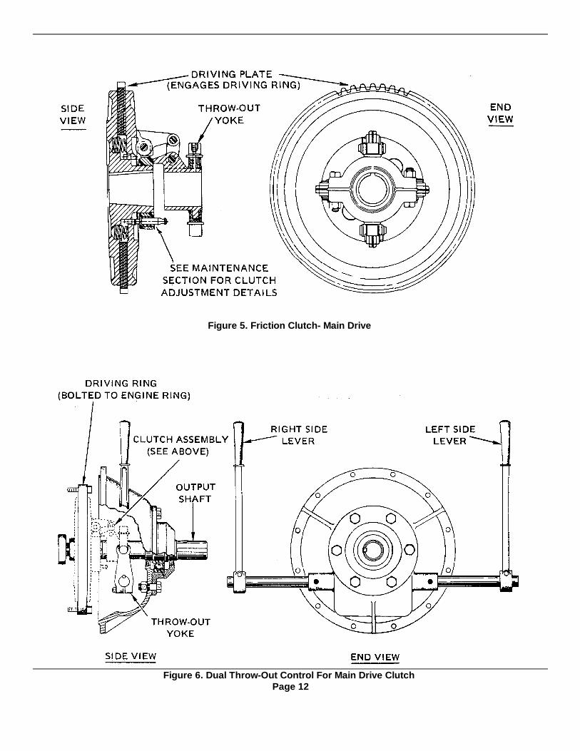
Figure 5. Friction Clutch- Main Drive
Figure 6. Dual Throw-Out Control For Main Drive ClutchPage 12
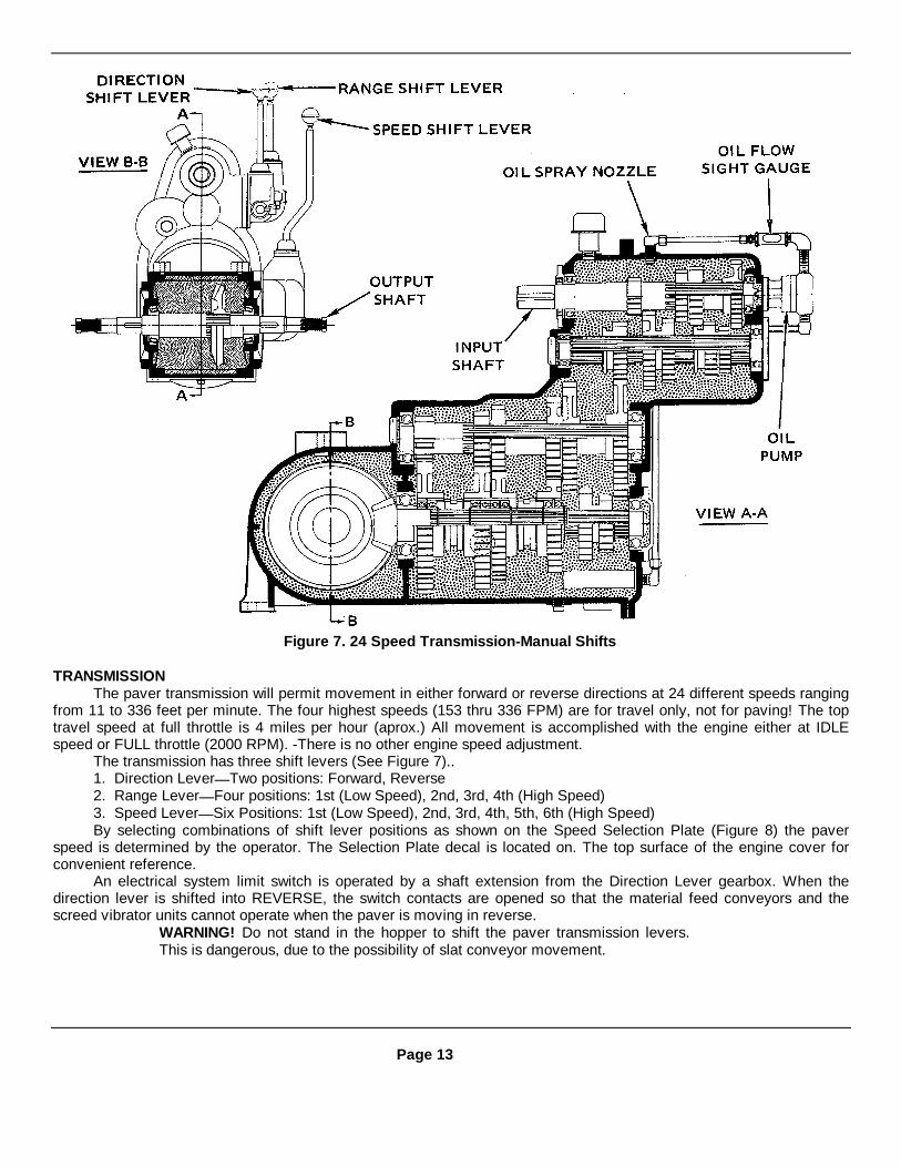
Figure 7. 24 Speed Transmission-Manual Shifts
TRANSMISSIONThe paver transmission will permit movement in either forward or reverse directions at 24 different speeds ranging
from 11 to 336 feet per minute. The four highest speeds (153 thru 336 FPM) are for travel only, not for paving! The toptravel speed at full throttle is 4 miles per hour (aprox.) All movement is accomplished with the engine either at IDLEspeed or FULL throttle (2000 RPM). -There is no other engine speed adjustment.
The transmission has three shift levers (See Figure 7)..1. Direction Lever Two positions: Forward, Reverse2. Range Lever Four positions: 1st (Low Speed), 2nd, 3rd, 4th (High Speed)3. Speed Lever Six Positions: 1st (Low Speed), 2nd, 3rd, 4th, 5th, 6th (High Speed)By selecting combinations of shift lever positions as shown on the Speed Selection Plate (Figure 8) the paver
speed is determined by the operator. The Selection Plate decal is located on. The top surface of the engine cover forconvenient reference.
An electrical system limit switch is operated by a shaft extension from the Direction Lever gearbox. When thedirection lever is shifted into REVERSE, the switch contacts are opened so that the material feed conveyors and thescreed vibrator units cannot operate when the paver is moving in reverse.
WARNING! Do not stand in the hopper to shift the paver transmission levers.This is dangerous, due to the possibility of slat conveyor movement.
Page 13
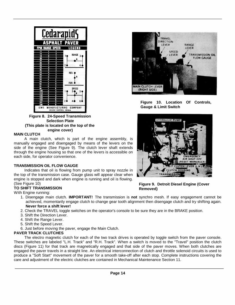
MAIN CLUTCHA main clutch, which is part of the engine assembly, is
manually engaged and disengaged by means of the levers on theside of the engine (See Figure 9). The clutch lever shaft extendsthrough the engine housing so that one of the levers is accessible oneach side, for operator convenience.
TRANSMISSION OIL FLOW GAUGEIndicates that oil is flowing from pump unit to spray nozzle in
the top of the transmission case. Gauge glass will appear clear whenengine is stopped and dark when engine is running and oil is flowing.(See Figure 10)TO SHIFT TRANSMISSIONWith Engine running:
1. Disengage main clutch. IMPORTANT! The transmission is not synchro mesh. If easy engagement cannot beachieved, momentarily engage clutch to change gear tooth alignment then disengage clutch and try shifting again.Never force a shift lever!
2. Check the TRAVEL toggle switches on the operator's console to be sure they are in the BRAKE position.3. Shift the Direction Lever.4. Shift the Range Lever.5. Shift the Speed Lever.6. Just before moving the paver, engage the Main Clutch.
PAVER TRACK CLUTCHESThe electro magnetic clutch for each of the two track drives is operated by toggle switch from the paver console.
These switches are labeled "L.H. Track" and "R.H. Track". When a switch is moved to the "Travel" position the clutchdiscs (Figure 11) for that track are magnetically engaged and that side of the paver moves. When both clutches areengaged the paver travels in a straight line. An electrical interconnection of clutch and throttle solenoid circuits is used toproduce a "Soft Start" movement of the paver for a smooth take-off after each stop. Complete instructions covering thecare and adjustment of the electric clutches are contained in Mechanical Maintenance Section 11.
Page 14
Figure 9. Detroit Diesel Engine (CoverRemoved)
Figure 8. 24-Speed TransmissionSelection Plate
(This plate is located on the top of theengine cover)
Figure 10. Location Of Controls,Gauge & Limit Switch

PAVER BRAKESThe electro-released brake for each of the two tracks is operated by toggle switch from the paver console. These
switches are labeled "L.H. Track" and "R.H. Track". When a switch is moved to the "Brake" position, the armature plateon the input shaft of the track gear case is magnetically attracted to the stationary friction plate on the gear case. Thislocks the shaft so that no movement of the track can occur. Each track brake operates independent of the other. (SeeFigure 12).
Depending upon the condition of the 12 VDC Battery, the electric brakes can be released whenever the control keyswitch is in the ON position. When all power is OFF, both brakes are locked ON. Complete instructions covering thecare, clearance checking, and repair of the electric brake are contained in the Mechanical Maintenance Section 11.ASPHALT FEED CLUTCHES (Slat and Screw Conveyors)
The two slat conveyors and the two screw conveyors which combine functions to move asphalt from the hopper tothe area ahead of the trailing screed, are operated by means of two electromagnetic clutches. Each clutch starts or stopsthe movement of one side of the feed system (Right hand or Left hand). By chain and sprocket connection, one slatconveyor and one screw conveyor operate simultaneously to feed one side. (SeeFigure 13) Each clutch is operated by means of a toggle switch on the operator'sconsole.Complete information on the care and adjustment of electric clutches iscontained in the Mechanical Maintenance Section 11)
Page 15
Figure 11. Location Of Clutch For RH Track
Figure 12. Location Of Brake For LH Track
Figure 13. Electric Clutches For Material Conveyors
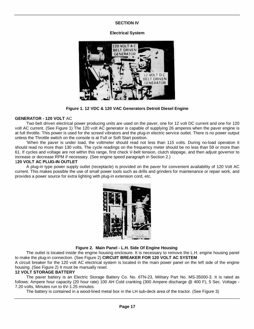
SECTION IV
Electrical System
Figure 1. 12 VDC & 120 VAC Generators Detroit Diesel Engine
GENERATOR - 120 VOLT ACTwo belt driven electrical power producing units are used on the paver, one for 12 volt DC current and one for 120
volt AC current. (See Figure 1) The 120 volt AC generator is capable of supplying 26 amperes when the paver engine isat full throttle. This power is used for the screed vibrators and the plug-in electric service outlet. There is no power outputunless the Throttle switch on the console is at Full or Soft Start position.
'When the paver is under load, the voltmeter should read not less than 115 volts. During no-load operation itshould read no more than 130 volts. The cycle readings on the frequency meter should be no less than 59 or more than61. If cycles and voltage are not within this range, first check V-belt tension, clutch slippage, and then adjust governor toincrease or decrease RPM if necessary. (See engine speed paragraph in Section 2.)120 VOLT AC PLUG-IN OUTLET
A plug-in type power supply outlet (receptacle) is provided on the paver for convenient availability of 120 Volt ACcurrent. This makes possible the use of small power tools such as drills and grinders for maintenance or repair work, andprovides a power source for extra lighting with plug-in extension cord, etc.
Figure 2. Main Panel - L.H. Side Of Engine HousingThe outlet is located inside the engine housing enclosure. It is necessary to remove the L.H. engine housing panel
to make the plug-in connection. (See Figure 2) CIRCUIT BREAKER FOR 120 VOLT AC SYSTEMA circuit breaker for the 120 volt AC electrical system is located in the main power panel on the left side of the enginehousing. (See Figure 2) It must be manually reset.12 VOLT STORAGE BATTERY
The paver battery is an Electric Storage Battery Co. No. 6TN-23, Military Part No. MS-35000-3. It is rated asfollows: Ampere hour capacity (20 hour rate) 100 AH Cold cranking (300 Ampere discharge @ 400 F), 5 Sec. Voltage -7.20 volts, Minutes run to 6V-1.25 minutes.
The battery is contained in a wood-lined metal box in the LH sub-deck area of the tractor. (See Figure 3)
Page 17

GENERATOR: (12 VDC) - See Figure 1The generator, driven by pulley and V-belt arrangement from the engine's electrical accessory drive shaft, is
dependent upon correct engine speed to produce the required voltage. This unit supplies 12 Volt DC current for the paverControl System and battery charging. In standard automobile fashion the battery supplies current for engine starter,ignition, lights, horn, screed heater, etc. It also supplies current to release the paver brakes (magnetic). It is thereforevitally important that the battery be kept in top efficiency condition at all times so that a full 12 volts aredelivered to all control circuits! A battery with bad cells will draw so much generator current and lower its availablevoltage so much that clutch coils and solenoid coils will not "pull in" properly. This allows clutches to slip and burn rapidly.IMPORTANT! Do not start a paver by jumping an unsatisfactory battery! Replace the battery with one in top condition sothat when the engine is idling the electric clutches and brakes work properly.
CAUTION! The generator is equipped with a voltage regulator which includesrectifier and isolation diodes. When charging or installing a battery be sureproper polarity is observed. Ground polarity of the battery and ground polarity ofthe generator must be the same. Reversal of polarity will destroy the diodesin the generator voltage regulator!
CIRCUIT BREAKERS FOR 12 VOLT DC SYSTEMThere are eight circuit breakers for the 12 volt DC electrical system. Four of them require manual reset after
overload cut-off. Four are automatic reset units. These automatic breakers have no overload indicator to show theirstatus. The circuit breaking function simply repeats until the overload situation in that circuit is corrected. The circuit,rating and location of each breaker is as follows:Circuit Rating Reset LocationThrottle Solenoid ....................................................... 15A ...........................................................Manual.......................................................Instru. PanelTravel Clutches ......................................................... 15A ...........................................................Manual.......................................................Instr. PanelFeed Clutches ........................................................... 15A ...........................................................Manual.......................................................Instr. PanelScreed Burner ........................................................... 30A ...........................................................Manual.......................................................Instr. PanelGauge Lights............................................................. IOA............................................................Auto...........................................................Instr. BoxFront Flood Lights ..................................................... 15A ...........................................................Auto...........................................................Instr. BoxConveyor Flood Lights............................................... 15A ...........................................................Auto...........................................................Instr. BoxRear Flood Lights ...................................................... 5SA...........................................................Auto...........................................................Instr. Box
RE-SETTING CIRCUIT BREAKERSIMPORTANT! Whenever a circuit breaker is tripped by an overload do not reset the breaker until a thorough
check has been made to locate the cause of the overload. The tell-tale odor of over-heated electrical equipment anddiscolored or melted wire insulation often help to locate a trouble source. It is best that someone with good electricalsystem knowledge perform this trouble check and reset the breaker.
Page 18
Figure 3. 12 Volt Battery Location - LHWalkway Removed
Figure 4. Location Of 12 VDC Circuit Breakers

MAIN ELECTRIC PANEL COMPONENTSFigure 5
12 Volt D.C. SystemsItem No. Description
1 Terminal Strips - 12 VDC Systems2 Spare Relay3 RH Track Clutch Relay - R74 LH Track Clutch Relay - R65 Engine Throttle Solenoid Relay - R46 Horn Relay - R37 RH Brake Relay - R88 LH Brake Relay- R59 LH Conveyor Clutch Relay - R1210 RH Conveyor Clutch Relay - R1311 Bleeder for Conveyor Clutch Circuits12 Bleeder for Track Clutch and Brake Circuits18 Ground Terminal
12 Volt A.C. SystemsItem No. Description
13 Duomatic Screed Control Relay - R10(Wired only when option is purchased)
14 Screed Vibrator System Relay- R 1115 Plug-in Outlet16 Circuit Breaker (Manual Reset)17 Terminal Strip - 120 VAC Systems18 Ground Terminal
Page 19
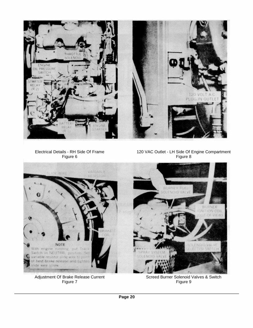
Electrical Details - RH Side Of FrameFigure 6
120 VAC Outlet - LH Side Of Engine CompartmentFigure 8
Adjustment Of Brake Release CurrentFigure 7
Screed Burner Solenoid Valves & SwitchFigure 9
Page 20
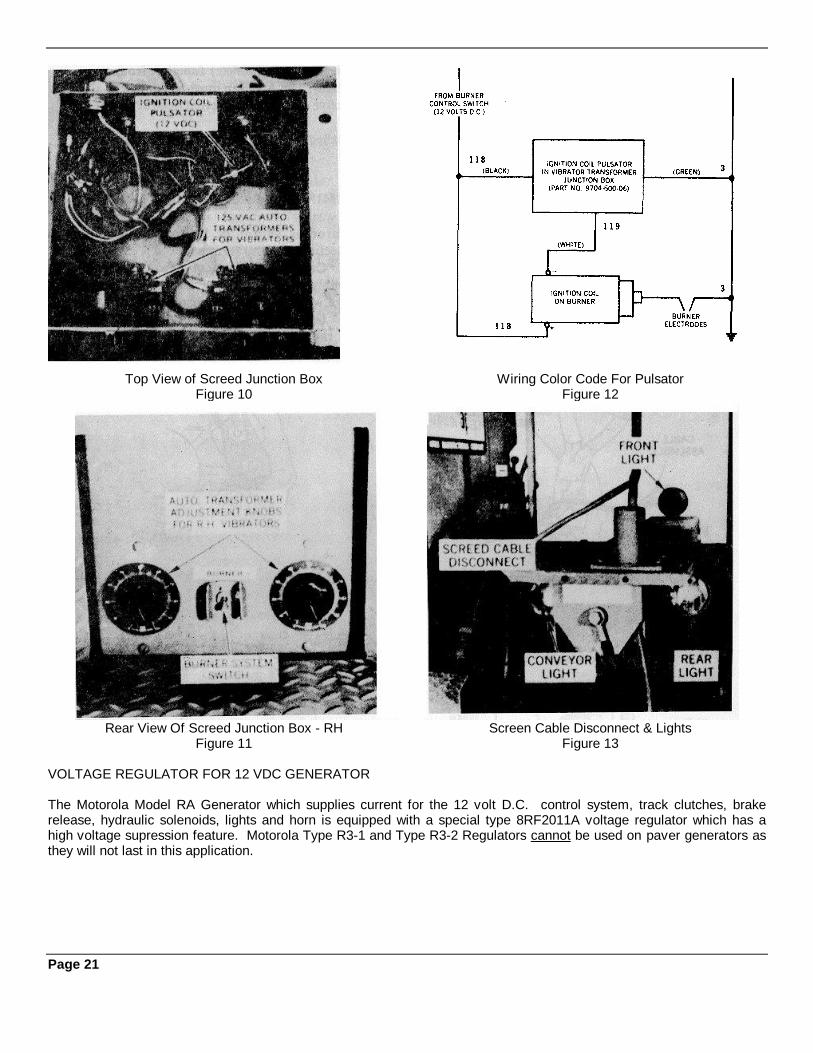
Top View of Screed Junction BoxFigure 10
Wiring Color Code For PulsatorFigure 12
Rear View Of Screed Junction Box - RHFigure 11
Screen Cable Disconnect & LightsFigure 13
VOLTAGE REGULATOR FOR 12 VDC GENERATOR
The Motorola Model RA Generator which supplies current for the 12 volt D.C. control system, track clutches, brakerelease, hydraulic solenoids, lights and horn is equipped with a special type 8RF2011A voltage regulator which has ahigh voltage supression feature. Motorola Type R3-1 and Type R3-2 Regulators cannot be used on paver generators asthey will not last in this application.
Page 21
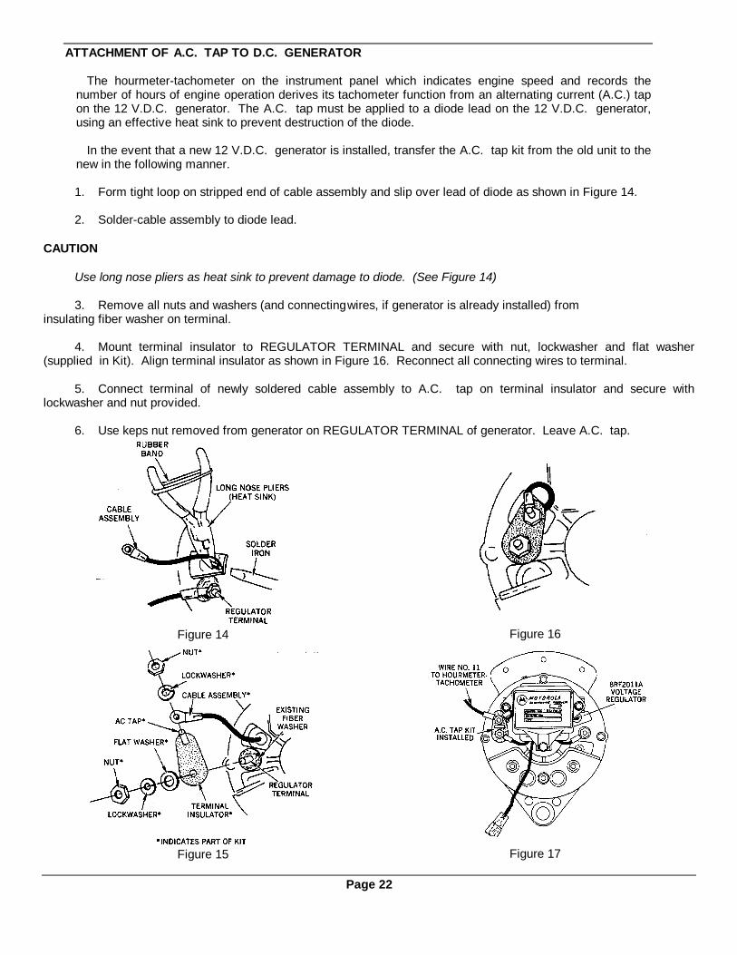
ATTACHMENT OF A.C. TAP TO D.C. GENERATOR
The hourmeter-tachometer on the instrument panel which indicates engine speed and records thenumber of hours of engine operation derives its tachometer function from an alternating current (A.C.) tapon the 12 V.D.C. generator. The A.C. tap must be applied to a diode lead on the 12 V.D.C. generator,using an effective heat sink to prevent destruction of the diode.
In the event that a new 12 V.D.C. generator is installed, transfer the A.C. tap kit from the old unit to thenew in the following manner.
1. Form tight loop on stripped end of cable assembly and slip over lead of diode as shown in Figure 14.
2. Solder-cable assembly to diode lead.
CAUTION
Use long nose pliers as heat sink to prevent damage to diode. (See Figure 14)
3. Remove all nuts and washers (and connectingwires, if generator is already installed) frominsulating fiber washer on terminal.
4. Mount terminal insulator to REGULATOR TERMINAL and secure with nut, lockwasher and flat washer(supplied in Kit). Align terminal insulator as shown in Figure 16. Reconnect all connecting wires to terminal.
5. Connect terminal of newly soldered cable assembly to A.C. tap on terminal insulator and secure withlockwasher and nut provided.
6. Use keps nut removed from generator on REGULATOR TERMINAL of generator. Leave A.C. tap.
Figure 14 Figure 16
Figure 15 Figure 17
Page 22

ELECTRICAL TROUBLESHOOTING
To ease troubleshooting and repair of electrical problems, it is necessary to have a reliable AC-DC volt-ohm meterand to have a thorough understanding of the meter and how the paver electrical system operates. Instructions on properuse of the volt-ohm meter are usually furnished with the instrument and should be read carefully before first use.Improper use can quickly render the meter inoperative.
The paver electrical system is made up basically of two different voltage supplies: 12 volts DC and 120 volts AC.The 12 VDC circuit is powered by a 12 volt battery. It is recharged by a Motorola generator with built-in voltage
regulator. (IMPORTANT: Regulator must be an R3-3 or 8RF201 IA with high voltage suppression feature.)The 120 volt AC circuit supplies power for the screed vibrators and the AC convenience outlet. Output of the AC
generator should be 130 volts - 61 hz with no load applied. Double check the frequency by "taching" the generator shaft.Speed should be 3660 RPM.
TROUBLESHOOTING METHOD
When the following troubleshooting guide is used, check out the possibility of a defective unit listed by substitutinga spare or by interchanging two identical units to see what change in operation (if any) occurs.
Refer to the schematic diagram when making voltage checks listed in the following charts. Wire numbers referredto are shown on the schematic. All voltages should be 12 volts DC, unless otherwise specified. A voltage at one point,but not at the following point indicates that there is difficulty in that area. The numbers listed will suggest the area ofremedy such as loose connections, broken wire, switch in wrong position, relay missing, dirty contacts, etc.
When taking a voltage reading, the first number listed in the chart is for the positive meter lead, and the secondnumber listed is for the negative meter lead.
For example: Check 17 to 3
Positive meter lead on 17Negative meter lead on 3
IMPORTANT FIRST STEP!
DC POWER
To begin checks, make sure there is 12 VDC from I to 3. Turn DC power switch to ON and check for 12 VDC from17 to 3. All circuit breakers are to be ON and 12 VDC should be present on load side of breakers. If not, check for afaulty breaker.
TROUBLESHOOTING STARTING CIRCUIT
DC power switch held in start position. Track switches in brake position.Engine does not start
Voltage check:(1) 13 to 3 - defective start-stop switch(2) 2 to 3 - defective R2 relay - voltage present indicates faulty starter or starter solenoid
Page 23
TROUBLESHOOTING THROTTLE CIRCUIT
Engine does not throttle up in full throttle positionVoltage checks:
(1) 48 to 3 - defective throttle switch or open wire 48 to relay R4(2) 4 to 3 - defective throttle breaker or breaker tripped - if tripped, check for bind in throttle linkage(3) 5 to 3 - defective R4 relay or relay socket - if voltage is present on throttle solenoid, check for faulty solenoid
Throttle works in full but not in soft-startOne or both track switches in travel FWD-REV limit switch in FWD.
Voltage checks:(1) 46 to 3 - defective FWD-REV limit switch(2) 47 to 3 - defective R6 and/or R7 relay or relay socket(3) 48 to 3 - defective soft-start side of throttle switch
TROUBLESHOOTING TRAVEL CIRCUIT
Brakes do not releaseTrack switches in neutral position.
Voltage checks: (LH side)(1) 35 to 3 - if present, LH track switch is defective or 35 is shorted to 12 VDC(2) 25 to 3 - defective R5 relay or relay socket(3) Check for approximately 6 VDC from 26 to 27 - if not, adjust 5 ohm resistor until 6 VDC is present or release
begins(4) Check for 6 VDC from 26 to 27 on brake coil - if present, check for defective brake coil - coil should have 3
ohms resistance
Voltage check: (RH side)(1) 38 to 3 - if present, RH track switch is defective or 38 shorted to 12 VDC(2) 31 to 3 - defective R8 relay or relay socket(3) Check for approximately 6 VDC from 32 to 30 - if not, adjust 5 ohm resistor until 6 VDC is present or release
begins(4) Check for 6 VDC from 32 to 30 on brake coil - if present, check for defective brake coil - coil should have 3
ohms resistance
Brakes do not energizeTrack switches in brake position
Voltage checks: (LH side)(1) 35 to 3 - defective LH track switch(2) 27 to 3 - defective R5 relay or relay socket(3) Check for 6 VDC from 27 to 26 - defective or misadjusted 5 ohm resistor(4) Turn travel circuit breaker OFF to see if permanent magnet in brake works
Voltage checks: (RH side)(1) 38 to 3 - defective RH track switch(2) 30 to 3 - defective R8 relay or relay socket(3) Check for 6 VDC from 27 to 26 - defective or misadjusted 5 ohm resistor(4) Turn travel circuit breaker OFF to see if permanent magnet in brake works.
(CONTINUED)
Page 24
TRAVEL CIRCUIT - Continued
Clutches do not pull inTrack switches in travel position.
Voltage checks: (LH side)(1) 36 to 3 - defective LH travel switch(2) Relay R6 should be energized - if not, check for bad relay coil or socket, or lack of continuity from 39 to 3.(3) 21 to 3 - defective R6 relay contact or socket(4) Check for defective clutch coil - should have 3.5 ohm resistance for standard torque and 1 ohm resistance for
hi-torque
Voltage checks: (RH side)(1) 37 to 3 - defective RH travel switch(2) Relay R7 should be energized - if not, check for faulty relay, socket, or lack of continuity from 39 to 3(3) 23 to 3 - defective R7 relay contact or socket(4) Check for defective clutch coil - should have 3.5 ohm resistance
TROUBLESHOOTING FEED CIRCUIT
LH Feed Conveyor does not runLH feed conveyor switch in MANUAL. FWD-REV limit switch in FORWARD.
Voltage checks:(1) 46 to 3 - defective FWD-REV limit switch(2) 52 to 3 - defective LH conveyor switch(3) Relay R12 should be energized - if not, check for defective R12 relay coil or socket(4) 56 to 3 - defective R12 relay contact(5) If voltage present - check for defective clutch coil
LH Feed Conveyor runs in MANUAL but not in AUTO.FWD-REV limit switch in FORWARD. One or both track switches in travel.
Voltage checks:(1) 47 to 3 - defective R6 and/or R7 relay contact(2) 51 to 3 - defective LH conveyor switch or defective diode(3) 52 to 3 - defective or tripped LH feed limit switch
RH Feed Conveyor does not runRH feed conveyor switch in MA NUA L. FWD- REV limit switch in FOR WA RD.
Voltage checks:(1) 46 to 3 - defective travel switch(2) 54 to 3 - defective RH conveyor switch(3) Relay R13 should be energized - if not, check for defective R13 relay coil or socket(4) 58 to 3 - defective R13 relay contact(5) If voltage present - check for defective clutch coil
RH Feed Conveyor runs in MANUAL but not in AUTO.FWD-REV limit switch in FORWARD. One or both track switches in travel.
Voltage checks:(1) 47 to 3 - defective R6 and/or R7 relay contact(2) 53 to 3 - defective RH conveyor switch or defective diode(3) 54 to 3 - defective or tripped RH feed limit switch
Page 25
TROUBLESHOOTING HYDRAULIC SOLENOIDS
Should be 12 VDC from 45 to 3.Screed does not go up
Screed lift switch held in UP positionVoltage checks:
(1) 63 to 3 - defective switch(2) 63 to 3 at solenoid - open wire to solenoid - if present, check for defective solenoid coil
Screed does not go downScreed lift switch held in DOWN position
Voltage checks:(1) 64 to 3 - defective switch(2) 64 to 3 at solenoid - open wire to solenoid - if present, check for defective solenoid coil
Hopper Wings do not go upHopper wing switch in UP position
Voltage checks:(1) 65 to 3 - defective switch(2) 65 to 3 at solenoid - open wire to solenoid - if present, check for defective solenoid coil
Hopper Wings do not go downHopper wing switch held in DOWN position.
Voltage checks:(1) 66 to 3 - defective switch(2) 66 to 3 at solenoid - open wire to solenoid - if present, check for defective solenoid coil
TROUBLESHOOTING DC BURNER ON SCREED
Burner Motor and Pulsator do not runBurner breaker ON. Burner-spray down switch in BURNER position.
Voltage checks:(1) 115 to 3 - defective burner breaker or wiring from meter box(2) 116 to 3 - defective burner switch(3) Check for good ground on entire systemBurner motor checkout (motor does not run)
Voltage checks:(a) 116 to 3 at motor - open motor cable(b) Check for defective burner motor
Pulsator checkout (No spark across ignitor points)Points adjusted properly. High tension lead from coil to one point in place.
Voltage checks:(a) 118 to 3 - defective burner switch(b) 119 to 3 - if the same as 118 to 3 - pulsator is not working. If no voltage is present - check coil
resistance (1.5 ohm)-if coil is okay, make sure wire 119is not grounded. If not - replace pulsator.
No fuel at nozzle of burnerCheck for 12 VDC at fuel oil solenoid (Wire #118). If present, check for defective solenoid. If solenoid is working
check for defective fuel pump.
Page 26
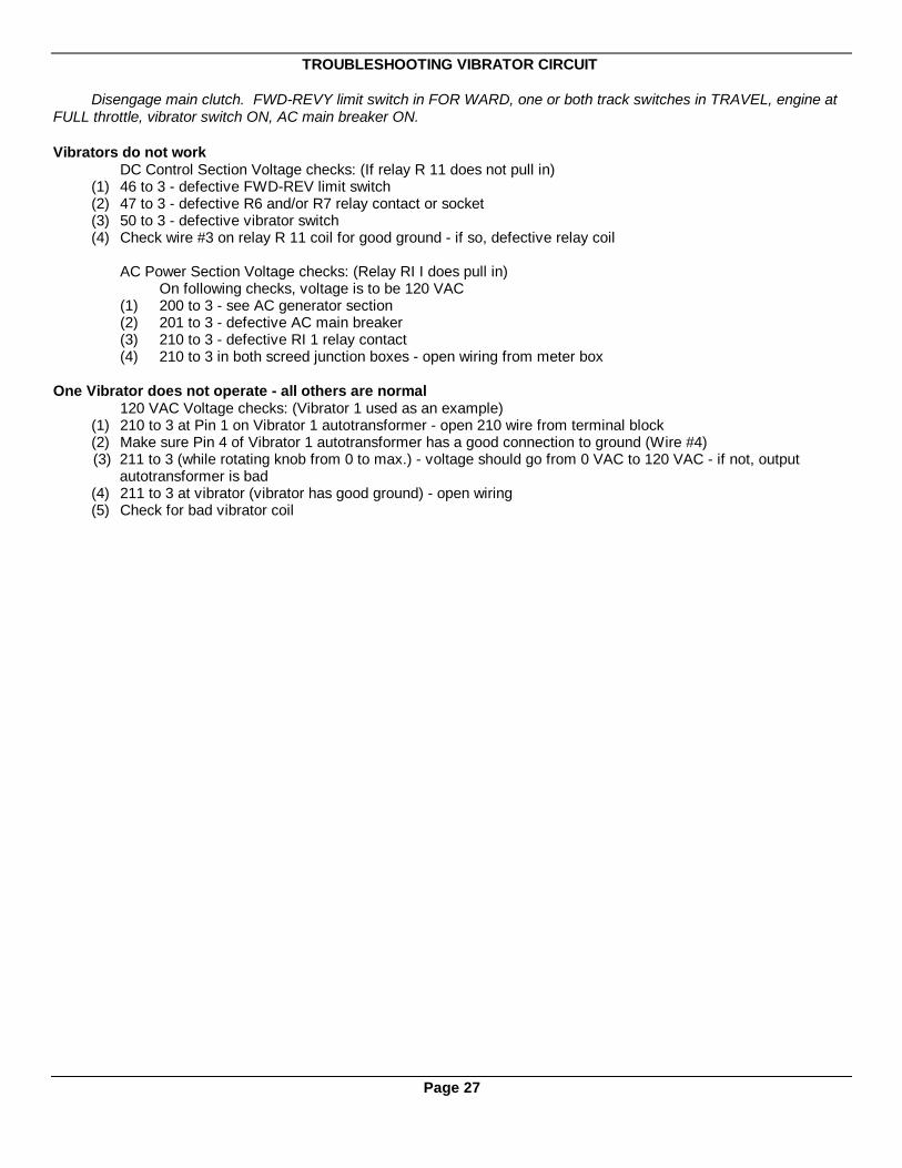
TROUBLESHOOTING VIBRATOR CIRCUIT
Disengage main clutch. FWD-REVY limit switch in FOR WARD, one or both track switches in TRAVEL, engine atFULL throttle, vibrator switch ON, AC main breaker ON.
Vibrators do not workDC Control Section Voltage checks: (If relay R 11 does not pull in)
(1) 46 to 3 - defective FWD-REV limit switch(2) 47 to 3 - defective R6 and/or R7 relay contact or socket(3) 50 to 3 - defective vibrator switch(4) Check wire #3 on relay R 11 coil for good ground - if so, defective relay coil
AC Power Section Voltage checks: (Relay RI I does pull in)On following checks, voltage is to be 120 VAC
(1) 200 to 3 - see AC generator section(2) 201 to 3 - defective AC main breaker(3) 210 to 3 - defective RI 1 relay contact(4) 210 to 3 in both screed junction boxes - open wiring from meter box
One Vibrator does not operate - all others are normal120 VAC Voltage checks: (Vibrator 1 used as an example)
(1) 210 to 3 at Pin 1 on Vibrator 1 autotransformer - open 210 wire from terminal block(2) Make sure Pin 4 of Vibrator 1 autotransformer has a good connection to ground (Wire #4)(3) 211 to 3 (while rotating knob from 0 to max.) - voltage should go from 0 VAC to 120 VAC - if not, output
autotransformer is bad(4) 211 to 3 at vibrator (vibrator has good ground) - open wiring(5) Check for bad vibrator coil
Page 27
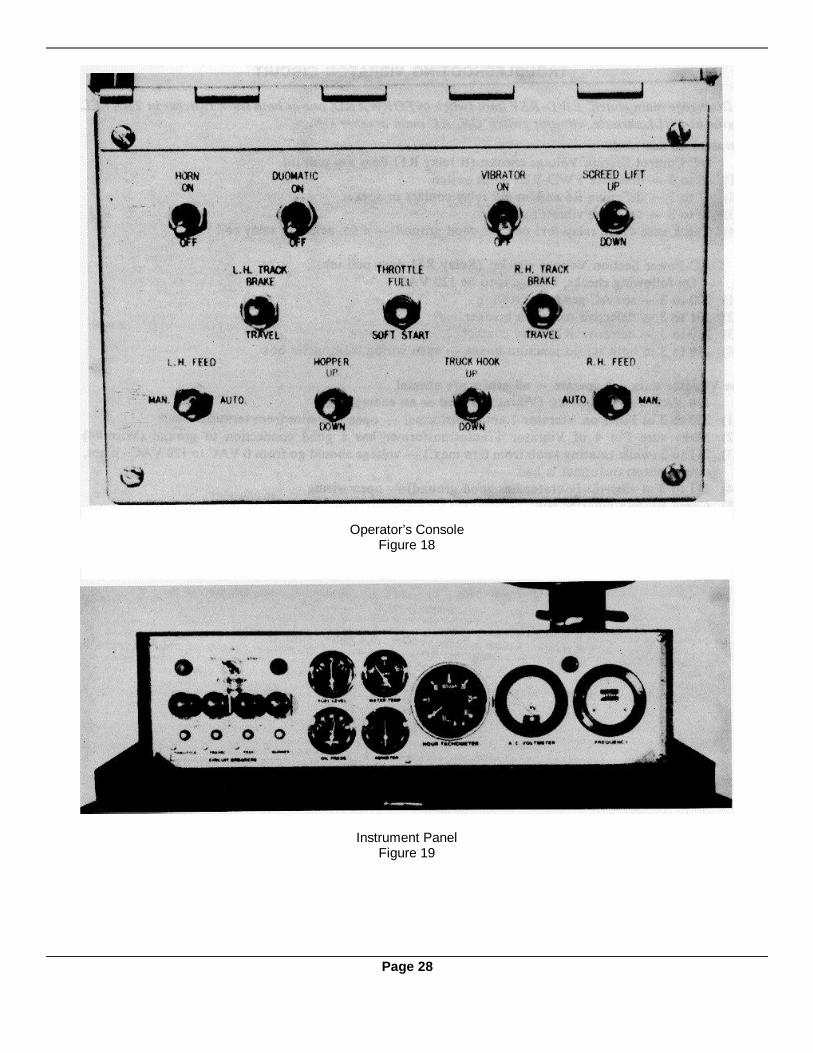
Operator’s ConsoleFigure 18
Instrument PanelFigure 19
Page 28

Page 29
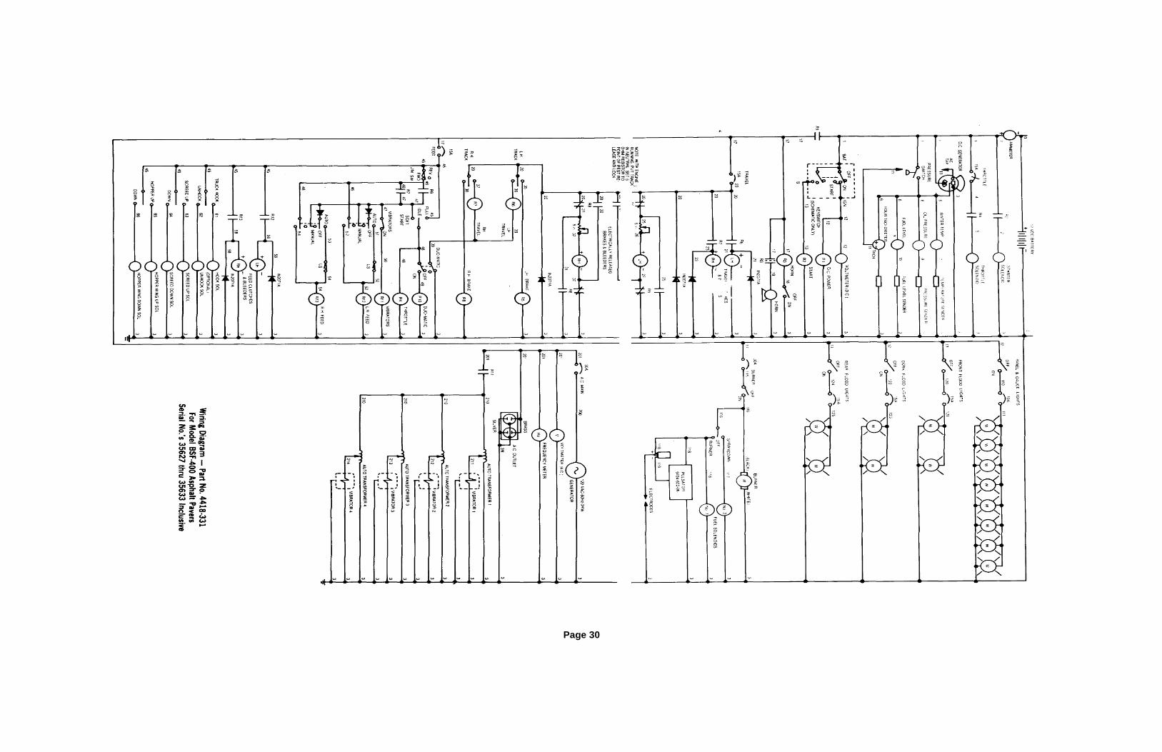
Page 30

SECTION V
Hydraulic System
(FOR OPERATION OF SCREED LIFT & HOPPER WINGS)
TABLE OF CONTENTS
Paragraph Subject Page
(1) Hydraulic System - General Description .............................................................33
(2) Fluid Level .........................................................................................................33
(3) Inspection For Leakage......................................................................................34
(4) Filter Element Change .......................................................................................34
(5) Filter Condition Gauge .......................................................................................34
(6) Hydraulic Fluid Change......................................................................................34
(7) Hydraulic Pump..................................................................................................34
(8) Toggle Switches and Electrical Connections ......................................................35
(9) Solenoid Valves - General..................................................................................36
(10) Solenoid Coil Testing By Substitution.................................................................36
(11) Manual Testing Of Solenoid Valve .....................................................................37
(12) Preparation For Dismantling Valve Bank............................................................38
(13) Dismantling Valve Bank .....................................................................................38
(14) Dismantling Solenoid Valve ...............................................................................38
(15) Hydraulic Holding Valve .....................................................................................40
(16) Pressure Relief Valve.........................................................................................40
(17) Throttle Valve ....................................................................................................41
(18) Hydraulic Cylinders ............................................................................................41
(19) Screed Lift Cables..............................................................................................43
(20) Hose and Tube Id6ntification..............................................................................43
(21) Hose Assembly ..................................................................................................43
(22) Hose Couplings..................................................................................................44
Hydraulic Throttle Shooting Chart...................................................................44 & 45
Schematic Diagram - Paver Hydraulic System...................................................46
Page 31

Representative Drawing of Hydraulic System ComponentsFigure 1
Top View of Valve BankFigure 2
Page 32
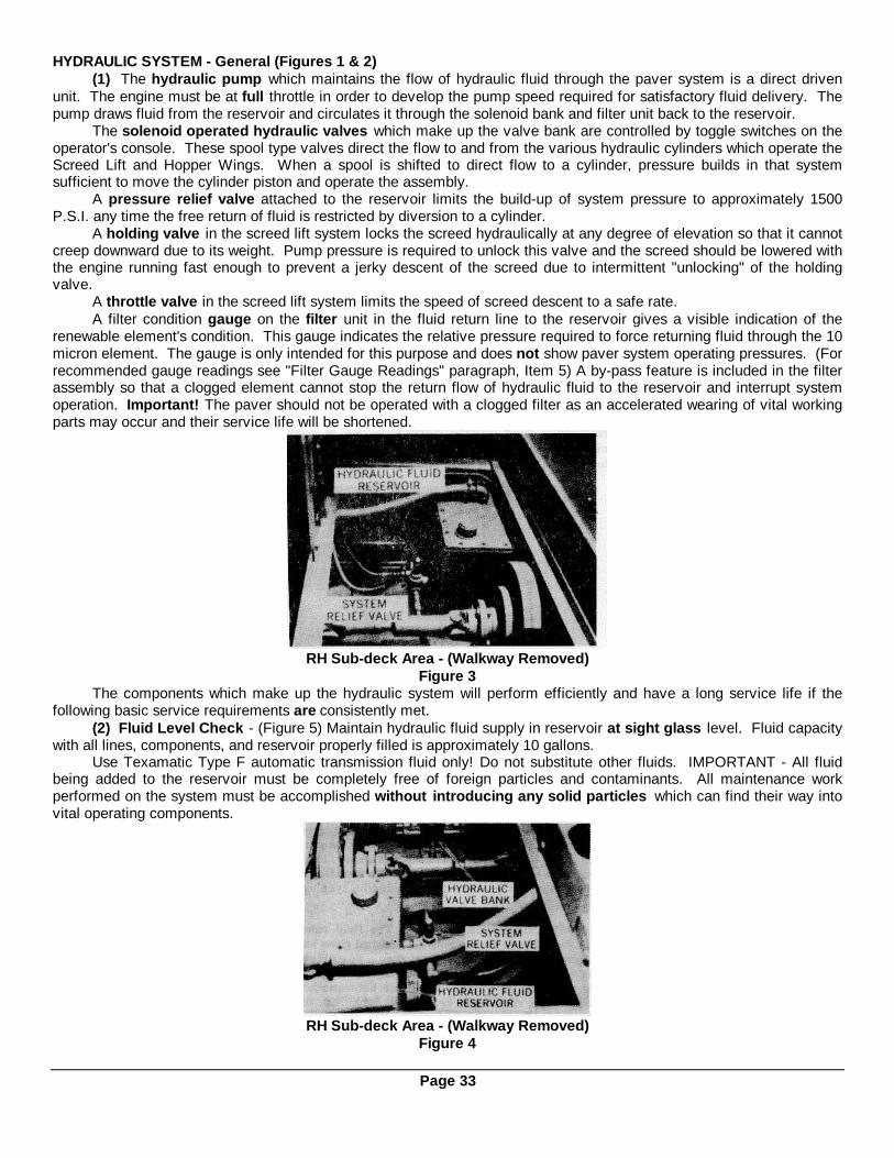
HYDRAULIC SYSTEM - General (Figures 1 & 2)(1) The hydraulic pump which maintains the flow of hydraulic fluid through the paver system is a direct driven
unit. The engine must be at full throttle in order to develop the pump speed required for satisfactory fluid delivery. Thepump draws fluid from the reservoir and circulates it through the solenoid bank and filter unit back to the reservoir.
The solenoid operated hydraulic valves which make up the valve bank are controlled by toggle switches on theoperator's console. These spool type valves direct the flow to and from the various hydraulic cylinders which operate theScreed Lift and Hopper Wings. When a spool is shifted to direct flow to a cylinder, pressure builds in that systemsufficient to move the cylinder piston and operate the assembly.
A pressure relief valve attached to the reservoir limits the build-up of system pressure to approximately 1500P.S.I. any time the free return of fluid is restricted by diversion to a cylinder.
A holding valve in the screed lift system locks the screed hydraulically at any degree of elevation so that it cannotcreep downward due to its weight. Pump pressure is required to unlock this valve and the screed should be lowered withthe engine running fast enough to prevent a jerky descent of the screed due to intermittent "unlocking" of the holdingvalve.
A throttle valve in the screed lift system limits the speed of screed descent to a safe rate.A filter condition gauge on the filter unit in the fluid return line to the reservoir gives a visible indication of the
renewable element's condition. This gauge indicates the relative pressure required to force returning fluid through the 10micron element. The gauge is only intended for this purpose and does not show paver system operating pressures. (Forrecommended gauge readings see "Filter Gauge Readings" paragraph, Item 5) A by-pass feature is included in the filterassembly so that a clogged element cannot stop the return flow of hydraulic fluid to the reservoir and interrupt systemoperation. Important! The paver should not be operated with a clogged filter as an accelerated wearing of vital workingparts may occur and their service life will be shortened.
RH Sub-deck Area - (Walkway Removed)Figure 3
The components which make up the hydraulic system will perform efficiently and have a long service life if thefollowing basic service requirements are consistently met.
(2) Fluid Level Check - (Figure 5) Maintain hydraulic fluid supply in reservoir at sight glass level. Fluid capacitywith all lines, components, and reservoir properly filled is approximately 10 gallons.
Use Texamatic Type F automatic transmission fluid only! Do not substitute other fluids. IMPORTANT - All fluidbeing added to the reservoir must be completely free of foreign particles and contaminants. All maintenance workperformed on the system must be accomplished without introducing any solid particles which can find their way intovital operating components.
RH Sub-deck Area - (Walkway Removed)Figure 4
Page 33
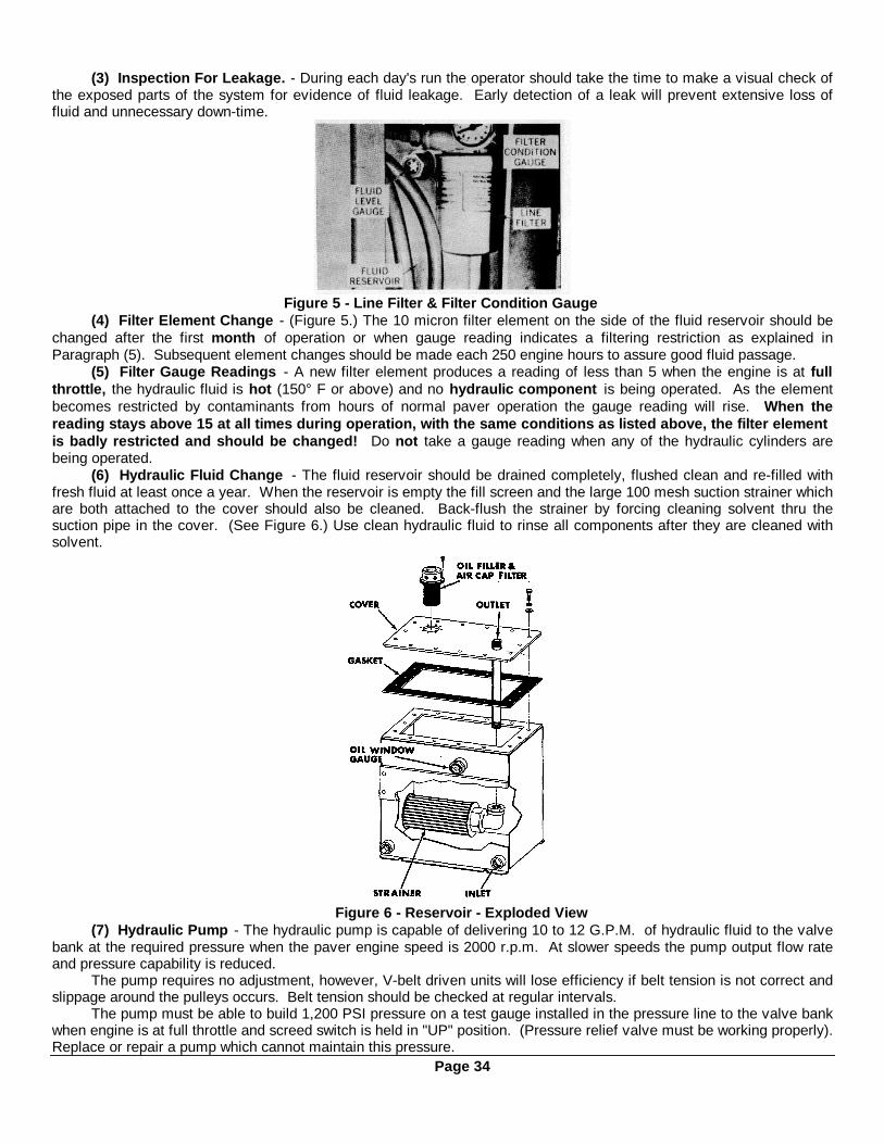
(3) Inspection For Leakage. - During each day's run the operator should take the time to make a visual check ofthe exposed parts of the system for evidence of fluid leakage. Early detection of a leak will prevent extensive loss offluid and unnecessary down-time.
Figure 5 - Line Filter & Filter Condition Gauge(4) Filter Element Change - (Figure 5.) The 10 micron filter element on the side of the fluid reservoir should be
changed after the first month of operation or when gauge reading indicates a filtering restriction as explained inParagraph (5). Subsequent element changes should be made each 250 engine hours to assure good fluid passage.
(5) Filter Gauge Readings - A new filter element produces a reading of less than 5 when the engine is at fullthrottle, the hydraulic fluid is hot (150° F or above) and no hydraulic component is being operated. As the elementbecomes restricted by contaminants from hours of normal paver operation the gauge reading will rise. When thereading stays above 15 at all times during operation, with the same conditions as listed above, the filter elementis badly restricted and should be changed! Do not take a gauge reading when any of the hydraulic cylinders arebeing operated.
(6) Hydraulic Fluid Change - The fluid reservoir should be drained completely, flushed clean and re-filled withfresh fluid at least once a year. When the reservoir is empty the fill screen and the large 100 mesh suction strainer whichare both attached to the cover should also be cleaned. Back-flush the strainer by forcing cleaning solvent thru thesuction pipe in the cover. (See Figure 6.) Use clean hydraulic fluid to rinse all components after they are cleaned withsolvent.
Figure 6 - Reservoir - Exploded View(7) Hydraulic Pump - The hydraulic pump is capable of delivering 10 to 12 G.P.M. of hydraulic fluid to the valve
bank at the required pressure when the paver engine speed is 2000 r.p.m. At slower speeds the pump output flow rateand pressure capability is reduced.
The pump requires no adjustment, however, V-belt driven units will lose efficiency if belt tension is not correct andslippage around the pulleys occurs. Belt tension should be checked at regular intervals.
The pump must be able to build 1,200 PSI pressure on a test gauge installed in the pressure line to the valve bankwhen engine is at full throttle and screed switch is held in "UP" position. (Pressure relief valve must be working properly).Replace or repair a pump which cannot maintain this pressure.
Page 34
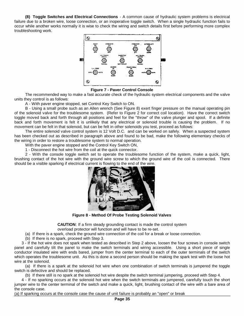
(8) Toggle Switches and Electrical Connections - A common cause of hydraulic system problems is electricalfailure due to a broken wire, loose connection, or an inoperative toggle switch. When a single hydraulic function fails tooccur while another works normally it is wise to check the wiring and switch details first before performing more complextroubleshooting work.
Figure 7 - Paver Control ConsoleThe recommended way to make a fast accurate check of the hydraulic system electrical components and the valve
units they control is as follows:A - With paver engine stopped, set Control Key Switch to ON.B - Using a small probe such as an Allen wrench (See Figure 8) exert finger pressure on the manual operating pin
of the solenoid valve for the troublesome system. (Refer to Figure 2 for correct coil location). Have the correct switchtoggle moved back and forth through all positions and feel for the "throw" of the valve plunger and spool. If a definiteback and forth movement is felt it is unlikely that any electrical or solenoid trouble is causing the problem. If nomovement can be felt in that solenoid, but can be felt in other solenoids you test, proceed as follows:
The entire solenoid valve control system is 12 Volt D.C. and can be worked on safely. When a suspected systemhas been checked out as described in paragraph above and found to be bad, make the following elementary checks ofthe wiring in order to restore a troublesome system to normal operation.
With the paver engine stopped and the Control Key Switch ON,1 - Disconnect the hot wire from the coil at the quick connector.2 - With the console toggle switch set to operate the troublesome function of the system, make a quick, light,
brushing contact of the hot wire with the ground wire screw to which the ground wire of the coil is connected. Thereshould be a visible sparking if electrical current is flowing to the end of the wire.
Figure 8 - Method Of Probe Testing Solenoid Valves
CAUTION : If a firm steady grounding contact is made the control systemoverload protector will function and will have to be re-set.
(a) If there is a spark, check the ground wire connection of the coil for a break or loose connection.(b) If there is no spark, proceed with Step 3.
3 - If the hot wire does not spark when tested as described in Step 2 above, loosen the four screws in console switchpanel and carefully tilt the panel to make the switch terminals and wiring accessible. Using a short piece of singleconductor insulated wire with ends bared, jumper from the center terminal to each of the outer terminals of the switchwhich operates the troublesome unit. As this is done a second person should be making the spark test with the loose hotwire at the solenoid.
(a) If there is a spark at the solenoid hot wire when one combination of switch terminals is jumpered the toggleswitch is defective and should be replaced.
(b) If there still is no spark at the solenoid hot wire despite the switch terminal jumpering, proceed with Step 4.4 - If no sparking occurs at the solenoid hot wire when the switch terminals are jumpered, carefully touch the short
jumper wire to the center terminal of the switch and make a quick, light, brushing contact of the wire with a bare area ofthe console case.(a) If sparking occurs at the console case the cause of unit failure is probably an "open" or break
Page 35

in the wiring from the operator's console to the junction box or from the junction box to the solenoid valve. If a visualcheck of the junction box does not disclose any broken wire, consult a qualified electrician. (Use paver electrical manual)
(b) If no sparking occurs at the console case, the problem is more complex and a qualified electrician should beconsulted.
Figure 9 - Solenoid Valve - Cross Section(9) Solenoid Valves - All of the 4-way solenoid operated directional valves used on the paver are identical units
(See Figures 9 and 10). They are double acting valves with spring return of the spool to the neutral position. Theoperation of each valve is controlled by a double throw toggle switch on the operator's console. When one of the switchcontacts is closed, a 12 V.D.C. valve coil is energized and the spool position is shifted by the plunger to connect internalporting so that hydraulic fluid under pressure flows to one end of the hydraulic cylinder(s). Fluid displaced by the movingcylinder piston flows through aligned ports of the same solenoid valve to the reservoir. When the toggle switch is movedto the opposite position, the opposite coil is energized and the spool is shifted to reverse the pressure and return flowports so that the cylinder moves in an opposite direction. When the switch is at the central "OFF" position the spool iscentered in the valve body by coil spring action and all ports connected to cylinders are closed so that no flow to or fromthe cylinders can occur.
(10) Solenoid Coil Testing by Substitution - If a coil is suspected to be the cause of a hydraulic system'sfailure, exchange the questionable coil with an adjacent coil which is known to be functioning properly.
METHOD: (See Figure 10)A - Remove Nut (1) and Sleeve (2) from each coil.B - Grasp Coil (3) and twist gently back and forth while pulling unit away from valve body.C - When both coils are clear of their tubes (6) slip the good coil onto the tube of the inoperative system and the
questionable coil onto the tube of the functioning system. Install the sleeves and nuts.D - Do not change the wiring connections. Operate the toggle switches with the exchange of coils in mind.Example: If the screed lift was inoperative and the hopper wing coil is substituted, operate the Hopper Wing
toggle switch to test the screed lift system (and vice versa). If the substitute coil will not operate the screed lift system,but the coil removed from it will operate the hopper wing system, then the screed lift valve may be jammed internally sothat it cannot be operated electrically. Put coils back in original locations and make a manual actuation test as outlinedin Paragraph (11).
If the substitute coil operates the troublesome system properly, interchange only the hot wire of each coil (quickdisconnect type). See if the substitute coil will still operate the valve when connected to the troublesome system's wiringcircuit. If the system again works properly, the suspected coil is truly defective and should be replaced. If the systemfails to work with the original wiring or if the suspected coil operates the other system, a bad toggle switch or a brokenwire are the actual cause of the failure. Refer to Paragraph (8).
Page 36

Figure 10 - 4 Way Solenoid Operated Hydraulic Valve - Exploded View(11) Manual Test Operation of Solenoid Valve - If a properly tested substitute coil and electrical wiring system
fails to operate a valve, a means is provided for manual shifting of the spool which may be temporarily jammed. (SeeFigures 9 & 11).METHOD:Use a ¼” diam. X 1 ½ ” long steel pin or similar tool which will enter the bore of the valve tube. With the paver engine atfull throttle, and all hydraulic system toggle switches in the OFF of center position, depress the pin in the bore of thevalve tube so that it contacts and moves the plunger, pin, and spool toward the opposite end of the valve. The first 1/8”movement will require nearly 25 pounds of force. As long as the valve is held manually depressed the cylinder operatedby the valve receives hydraulic fluid. If the spool has been jammed by dirt particles the flushing action of flow throughthe valve may permanently correct the problem and normal operation can be resumed. Do not use unreasonablepressure for manual shifting! If the spool cannot be manually shifted or fails to return by spring action to the OFFposition, the valve should be completely dismantled, inspected, cleaned, and test operated. (See following paragraph) Ifmanual shifting succeeds in operating the system, try electrical operation again to see whether the coil’s magnetic forceis strong enough to consistently move and hold the plunger.
Figure 11 - Manual Operation of Solenoid Valve
Page 37
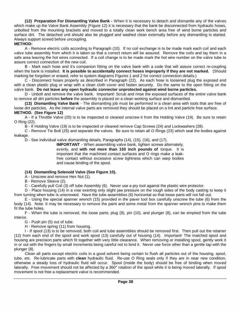
(12) Preparation For Dismantling Valve Bank - When it is necessary to detach and dismantle any of the valveswhich make up the Valve Bank Assembly (Figure 12) it is necessary that the bank be disconnected from hydraulic hoses,unbolted from the mounting brackets and moved to a totally clean work bench area free of wind borne particles andsurface dirt. The detached unit should also be plugged and washed clean externally before any dismantling is started.Always support screed before uncoupling.METHOD:
A - Remove electric coils according to Paragraph (10). If no coil exchange is to be made mark each coil and eachvalve tube assembly from which it is taken so that a correct return will be assured. Remove the coils and lay them in asafe area leaving the hot wires connected. If a coil change is to be made mark the hot wire number on the valve tube toassure correct connection of the new coil.
B - Mark each hose and it's companion fitting on the valve bank with a code that will assure correct re-couplingwhen the bank is installed. It is possible to accidentally connect hoses improperly if they are not marked. (Shouldmarking be forgotten or erased, refer to system diagrams Figures 1 and 2 for correct connection details.)
C - Disconnect hoses properly as described in Paragraph (22). As each hose is loosened plug the exposed endwith a clean plastic plug or wrap with a clean cloth cover and fasten securely. Do the same to the open fitting on thevalve bank. Do not leave any open hydraulic connector unprotected against wind borne particles.
D - Unbolt and remove the valve bank. Important! Scrub and rinse the exposed surfaces of the entire valve bankto remove all dirt particles before the assembly is placed on a clean working surface and dismantled.
(13) Dismantling Valve Bank - The dismantling job must be performed in a clean area with tools that are free ofloose dirt particles. As the internal valve parts are removed they should be placed on a lint and particle free surface.METHOD. (See Figure 12)
A - If a Throttle Valve (20) is to be inspected or cleaned unscrew it from the Holding Valve (19). Be sure to retainO Ring (22).
B - If Holding Valve (19) is to be inspected or cleaned remove Cap Screws (24) and Lockwashers (28).C - Remove Tie Bolt (25) and separate the valves. Be sure to retain all O Rings (23) which seal the bodies against
leakage.D - See individual valve dismantling details, Paragraphs (14), (15), (16), and (17).
IMPORTANT - When assembling valve bank, tighten screws alternately,evenly, and with not more than 150 inch pounds of torque. It isimportant that the machined contact surfaces and O rings make a leak-free contact without excessive screw tightness which can warp bodiesand cause binding of the spool.
(14) Dismantling Solenoid Valve (See Figure 10).A - Unscrew and remove Hex Nut (1).B - Remove Sleeve (2).C - Carefully pull Coil (3) off tube Assembly (6). Never use a pry tool against the plastic wire protector.D - Place housing (14) in a vise exerting only slight jaw pressure on the rough sides of the body casting to keep it
from turning when tube is unscrewed. Have the tube assemblies (6) horizontal so that loose parts will not fall out.E - Using the special spanner wrench (15) provided in the paver tool box carefully unscrew the tube (6) from the
body (14). Note: It may be necessary to remove the paint and some metal from the spanner wrench pins to make themfit the tube holes.
F - When the tube is removed, the loose parts; plug (9), pin (10), and plunger (8), can be emptied from the tubeinterior.
G - Push pin (5) out of tube.H - Remove spring (11) from housing.I - If spool (13) is to be removed, both coil and tube assemblies should be removed first. Then pull out the retainer
(12) from each end of the spool and work spool (13) carefully out of housing (14). Important! The matched spool andhousing are precision parts which fit together with very little clearance. When removing or installing spool, gently work itin or out with the fingers by small increments being careful not to bind it. Never use force other than a gentle tap with theplunger (8).
Clean all parts except electric coils in a good solvent being certain to flush all particles out of the housing, spool,tube, etc. Re-lubricate parts with clean hydraulic fluid. Re-use O Ring seals only if they are in near new condition,otherwise a steady loss of hydraulic fluid will occur. Spool (inside the body) should be free of binding when movedlaterally. Free movement should not be affected by a 360° rotation of the spool while it is being moved laterally. If spoolmovement is not free a replacement valve is recommended.
Page 38
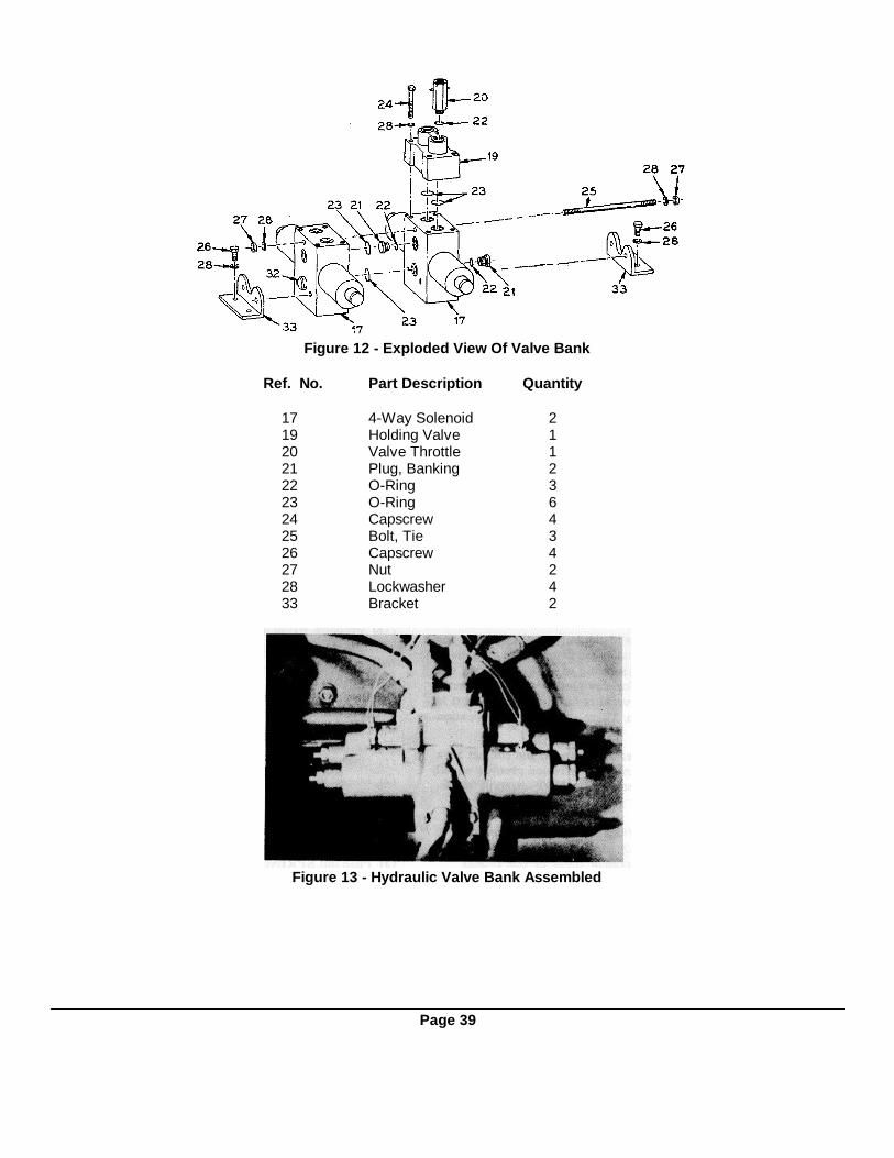
Figure 12 - Exploded View Of Valve Bank
Ref. No. Part Description Quantity
17 4-Way Solenoid 219 Holding Valve 120 Valve Throttle 121 Plug, Banking 222 O-Ring 323 O-Ring 624 Capscrew 425 Bolt, Tie 326 Capscrew 427 Nut 228 Lockwasher 433 Bracket 2
Figure 13 - Hydraulic Valve Bank Assembled
Page 39
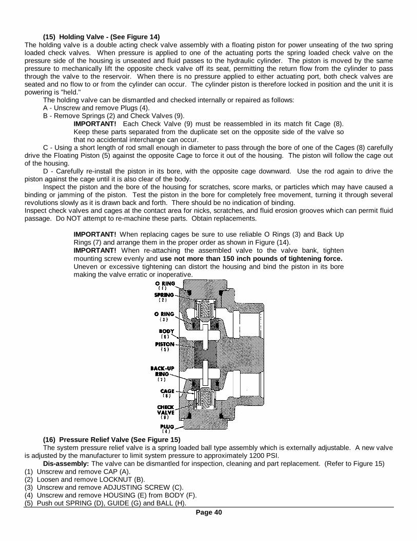
(15) Holding Valve - (See Figure 14)The holding valve is a double acting check valve assembly with a floating piston for power unseating of the two springloaded check valves. When pressure is applied to one of the actuating ports the spring loaded check valve on thepressure side of the housing is unseated and fluid passes to the hydraulic cylinder. The piston is moved by the samepressure to mechanically lift the opposite check valve off its seat, permitting the return flow from the cylinder to passthrough the valve to the reservoir. When there is no pressure applied to either actuating port, both check valves areseated and no flow to or from the cylinder can occur. The cylinder piston is therefore locked in position and the unit it ispowering is "held."
The holding valve can be dismantled and checked internally or repaired as follows:A - Unscrew and remove Plugs (4).B - Remove Springs (2) and Check Valves (9).
IMPORTANT! Each Check Valve (9) must be reassembled in its match fit Cage (8).Keep these parts separated from the duplicate set on the opposite side of the valve sothat no accidental interchange can occur.
C - Using a short length of rod small enough in diameter to pass through the bore of one of the Cages (8) carefullydrive the Floating Piston (5) against the opposite Cage to force it out of the housing. The piston will follow the cage outof the housing.
D - Carefully re-install the piston in its bore, with the opposite cage downward. Use the rod again to drive thepiston against the cage until it is also clear of the body.
Inspect the piston and the bore of the housing for scratches, score marks, or particles which may have caused abinding or jamming of the piston. Test the piston in the bore for completely free movement, turning it through severalrevolutions slowly as it is drawn back and forth. There should be no indication of binding.Inspect check valves and cages at the contact area for nicks, scratches, and fluid erosion grooves which can permit fluidpassage. Do NOT attempt to re-machine these parts. Obtain replacements.
IMPORTANT! When replacing cages be sure to use reliable O Rings (3) and Back UpRings (7) and arrange them in the proper order as shown in Figure (14).IMPORTANT! When re-attaching the assembled valve to the valve bank, tightenmounting screw evenly and use not more than 150 inch pounds of tightening force.Uneven or excessive tightening can distort the housing and bind the piston in its boremaking the valve erratic or inoperative.
(16) Pressure Relief Valve (See Figure 15)The system pressure relief valve is a spring loaded ball type assembly which is externally adjustable. A new valve
is adjusted by the manufacturer to limit system pressure to approximately 1200 PSI.Dis-assembly: The valve can be dismantled for inspection, cleaning and part replacement. (Refer to Figure 15)
(1) Unscrew and remove CAP (A).(2) Loosen and remove LOCKNUT (B).(3) Unscrew and remove ADJUSTING SCREW (C).(4) Unscrew and remove HOUSING (E) from BODY (F).(5) Push out SPRING (D), GUIDE (G) and BALL (H).
Page 40

Figure 15 - Pressure Relief Valve - Cross Section(6) Inspect all parts for wear, burrs, etc. Be sure all gaskets and seals are in good condition. Replace if questionable.(7) Before re-assembling, clean all parts thoroughly so that no foreign particles are introduced into the valve andhydraulic system.Re-setting Relief Pressure
IMPORTANT!To re-set the valve for 1500 PSI relief, proceed as follows:(a) Back-off (counterclockwise) adjusting screw (C) so that the valve will by-pass fluid at low pressure.(b) Install an accurate pressure gauge in the gauge port at the rear corner of the engine radiator shroud.(c) Run engine at Full speed.(d) Hold hopper wing switch at UP position and turn valve adjusting screw (C) inward (clockwise) to slowly raise
gauge pressure to 1500 PSI. Hold screw (C) and tighten locknut (B). Re-check gauge for 1500 PSI after tighteninglocknut.
(e) Hold hopper wing switch at DOWN position to re-check relief setting. Repeat test several times.(f) Install valve cap (A).(17) Throttle Valve - (See Figure 16) - Throttle valves are used in the "down" phase of the screed lift system and
in both phases of the optional truck hook system. The throttle valve in a two directional line allows unrestricted flow inone direction and metered or restricted flow in the opposite direction. In the case of the screed lift, the flow in the RAISEdirection is unrestricted while the return flow in the LOWER direction is restricted by a 3/32" DIAM. orifice. This permitsthe screed to raise at moderate speed but to descend at a slower safe rate. A drilled poppet is the only moving part. Thevalve can be easily disconnected for examination of the orifice for presence of foreign matter. The orifice can be probedclear using a piece of 1/16" diam. wire. If probing succeeds in clearing a blockage the valve should then be removedfrom the line and flushed clean of particles.
Figure 16 - Throttle Valve - Cross Section(18) Hydraulic Cylinders - (See Figures 17 & 18) The hydraulic cylinders used on Cedarapids pavers are
selected for efficient service and maximum durability. Very little trouble is normally experienced unless the hydraulicfluid is contaminated by foreign particles which find their way into cylinders and cause rapid seal wear. Heavy duty wipertype seals for the exposed rods help to minimize contamination. These parts should be maintained in top condition.If severe contamination of the hydraulic fluid has occurred and it is likely that a large quantity of particles has reached thecylinders, it is wise to flush them thoroughly with a suitable solvent. Replace seals when worn so that leakage is not athreat to efficient system operation.
A worn piston seal will permit leakage of fluid around the seal from the pressure to the discharge side of thecylinder. The result is sluggish movement of the piston rod or a failure to maintain rod position. Seal replacement is theonly solution.
Page 41

Figure 18
Item Description Quantity Item Description Quantity1 Piston 1 11 *O-Ring 12 Piston 1 12 *O-Ring 13 Tube, 2nd Stage 1 13 *Back Up Washer 14 Tube, 1st Stage 1 14 *O-Ring 15 Case 1 15 *Back Up Washer 16 Head 1 16 *U-Cup and Load O-Ring 17 Head 1 17 *U-Cup and Load O-Ring 18 *Piston Ring 1 18 *Seal, Wiper 19 *Piston Ring 1 19 *Seal, Wiper 110 *O-Ring 1
*NOTE: These Parts Purchased as a Repair Kit
Page 42
Figure 17

Figure 19 - Tilting Hopper Wings Figure 20 - Screed Lift Cylinder - Cut-away View
(19) Screed Lift Cables - Raising and lowering of the heavy screed assembly is accomplished through anarrangement of hydraulic cylinders, flexible cables, and pulleys. (See Figure 20). Because of the mechanical portion ofthe system which is for the most part hidden from the operator's view, it is wise to examine the cylinder operated pulleythrough the under side opening in any event of uneven screed movement. This will eliminate unnecessary hydraulicsystem trouble-shooting in the event the actual cause is the binding or jamming of a cable.
(20) Hose and Tube Identification - Each hose and tube is identified with a tag on one end as shown in Figure21. The number shown 38-34 corresponds with the last four numbers of the hose or tube assembly part number 5032-201-38-34.
Figure 21(21) Hose Assembly - The rubber-covered wire braid hoses used throughout the hydraulic system will give
trouble-free service and long life if properly maintained.Periodically check hose position to make sure they are not rubbing against moving parts or supported on sharp
steel edges.The hose end fittings are (no skive) re-usable hose fittings, to make it possible to repair the hose on the job site.Replace rubber-covered hose as follows:(1) Disassemble fitting nipple by turning it out of hose socket.(2) Disassemble hose socket by turning it off the rubber hose.(3) Clean steel socket and nipple.(4) Dip ends of new hose into hoze-oil lubricant and then thread the socket onto the rubber hose.
Do not cut inner or outer covering for assembly.(5) Thread nipple to socket.(6) Clean fitting and interior of hose. CAUTION: Flush hose with solvent before installing into system.
Page 43
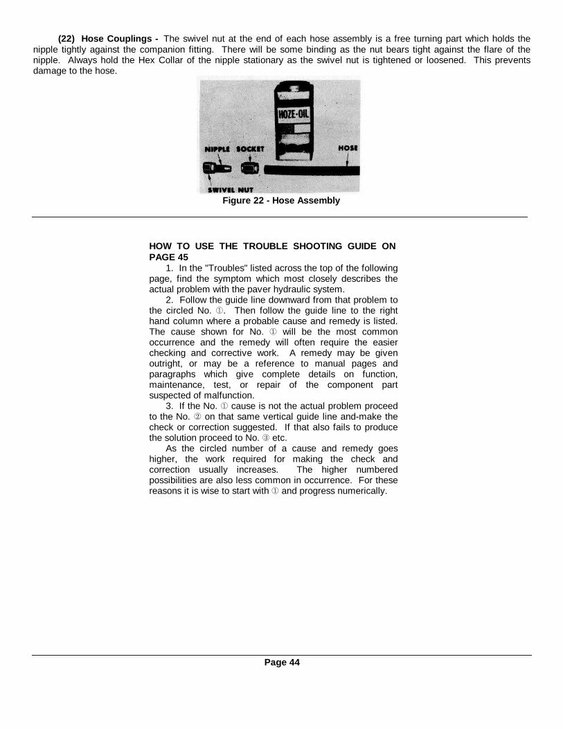
(22) Hose Couplings - The swivel nut at the end of each hose assembly is a free turning part which holds thenipple tightly against the companion fitting. There will be some binding as the nut bears tight against the flare of thenipple. Always hold the Hex Collar of the nipple stationary as the swivel nut is tightened or loosened. This preventsdamage to the hose.
Figure 22 - Hose Assembly
HOW TO USE THE TROUBLE SHOOTING GUIDE ONPAGE 45
1. In the "Troubles" listed across the top of the followingpage, find the symptom which most closely describes theactual problem with the paver hydraulic system.
2. Follow the guide line downward from that problem tothe circled No. . Then follow the guide line to the righthand column where a probable cause and remedy is listed.The cause shown for No. will be the most commonoccurrence and the remedy will often require the easierchecking and corrective work. A remedy may be givenoutright, or may be a reference to manual pages andparagraphs which give complete details on function,maintenance, test, or repair of the component partsuspected of malfunction.
3. If the No. cause is not the actual problem proceedto the No. on that same vertical guide line and-make thecheck or correction suggested. If that also fails to producethe solution proceed to No. etc.
As the circled number of a cause and remedy goeshigher, the work required for making the check andcorrection usually increases. The higher numberedpossibilities are also less common in occurrence. For thesereasons it is wise to start with and progress numerically.
Page 44

TROUBLE-SHOOTING GUIDE FOR BSF-400 PAVER HYDRAULIC SYSTEM
Page 45
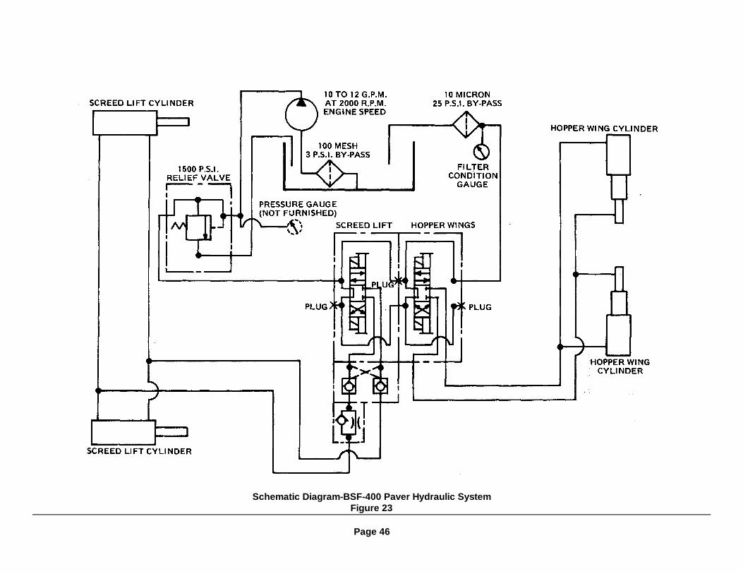
Schematic Diagram-BSF-400 Paver Hydraulic SystemFigure 23
Page 46
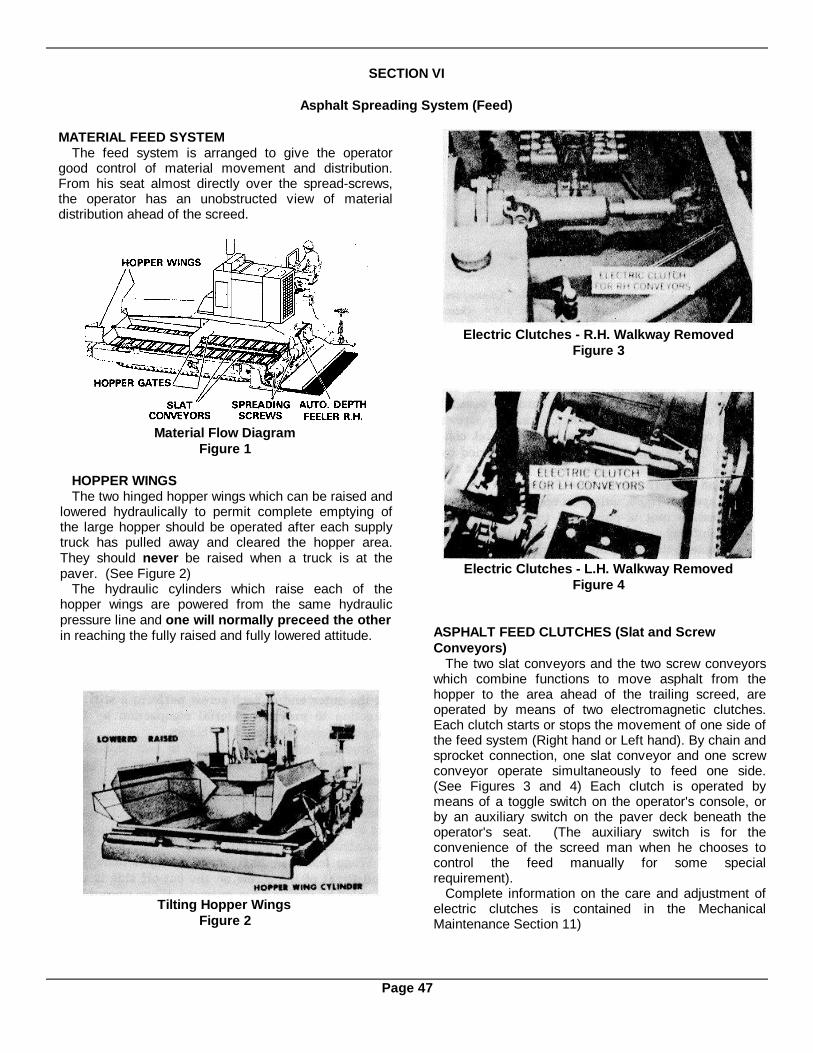
SECTION VI
Asphalt Spreading System (Feed)
MATERIAL FEED SYSTEMThe feed system is arranged to give the operator
good control of material movement and distribution.From his seat almost directly over the spread-screws,the operator has an unobstructed view of materialdistribution ahead of the screed.
Material Flow DiagramFigure 1
HOPPER WINGSThe two hinged hopper wings which can be raised and
lowered hydraulically to permit complete emptying ofthe large hopper should be operated after each supplytruck has pulled away and cleared the hopper area.They should never be raised when a truck is at thepaver. (See Figure 2)
The hydraulic cylinders which raise each of thehopper wings are powered from the same hydraulicpressure line and one will normally preceed the otherin reaching the fully raised and fully lowered attitude.
Tilting Hopper WingsFigure 2
Electric Clutches - R.H. Walkway RemovedFigure 3
Electric Clutches - L.H. Walkway RemovedFigure 4
ASPHALT FEED CLUTCHES (Slat and ScrewConveyors)
The two slat conveyors and the two screw conveyorswhich combine functions to move asphalt from thehopper to the area ahead of the trailing screed, areoperated by means of two electromagnetic clutches.Each clutch starts or stops the movement of one side ofthe feed system (Right hand or Left hand). By chain andsprocket connection, one slat conveyor and one screwconveyor operate simultaneously to feed one side.(See Figures 3 and 4) Each clutch is operated bymeans of a toggle switch on the operator's console, orby an auxiliary switch on the paver deck beneath theoperator's seat. (The auxiliary switch is for theconvenience of the screed man when he chooses tocontrol the feed manually for some specialrequirement).
Complete information on the care and adjustment ofelectric clutches is contained in the MechanicalMaintenance Section 11)
Page 47

Slat Conveyors and Spreading Screws(Screed Removed)
Figure 5SLAT CONVEYORS
Two slat conveyors move material from the bottom ofthe receiving hopper through parallel tunnel areas to eachof the two spreading screws which operate in conjunctionwith the slat conveyors. The depth of material moved isvaried by manual adjustment of fixed gates located at thehead end of each tunnel. (See Figure 5)
Slat speed is fixed, unless an optional two-speedtransmission unit is purchased to permit a 30% speedshift when required. With the fixed speed arrangementthe drive may be either the high or the low range.
Each slat conveyor and its companion spreading screware controlled by electric clutch action. The clutches canbe engaged manually by toggle switch movement at theoperators console, or can be controlled automatically by amaterial depth feeler if the console toggle switch is set atAUTO. (See details of automatic operation in followingparagraphs covering conveyors).
Bottom View of Tractor AssemblyFigure 6
IMPORTANT! The slat conveyors arebuilt to run in only one direction. Whenthe paver is shifted into Reverse gear forbacking, a micro switch at the gear box isactuated to open the conveyor clutchcircuits so that no reverse movement ofthe slats can occur. This limit switch(Section 8, Figure 4) must always bekept in adjustment!
SPREADING SCREWSThe two spreading screws which operate in conjunction
with the slat conveyors receive material as it is broughtthrough the tunnel areas near the center of the tractorunit. The opposing pitch of the screw blades forces thematerial outward toward the ends of the screed. A set ofspecial blades on each spreader screw at its inner endhas a reverse slant which assures placement of adequatematerial in the center area. Agitators at the outer end ofeach screw perform a stirring function to prevent materialcompaction by the screws against the retaining blades.
Spreader screws are offered in two diameters fordifferent feeding rates; 12" diameter for lower volumefeeding and 14" diameter for higher volume feeding.Whenever extreme wear reduces the diameter of a screwby ½ the tips should be built up or the blades refaced tothe original O.D. (See Maintenance Section 11).
When less than 10 ft. wide paving is done, the endflight of the screw on the cut-off side is uncoupled bysliding a key outward. When uncoupled the outer flight nolonger moves material. (See Figure 5).
Page 48

When extra wide paving is done, the spreader screwsmust be extended to match the extensions added to thescreed. Screw extensions are 12" Long (See Figure 7)and each includes a drive shaft extension for couplingpurposes.
Screw Conveyor Extensions (Uncoupled)Figure 7
EXTENDING SPREADER SCREWSWhen screed extensions are added and screws
are to be extended, proceed as follows:1. Remove nut and bolt which holds agitator section
and slide agitator off the shaft.2. Assemble as many screw extensions as needed.
(See Figures 7 and 8).3. Slide the socket end of the new assembly onto the
drive shaft and install the bolt and nut. Always usehardened bolts which have maximum shear strength.
4. Install the agitator on the end of the outer extensionshaft.
MATERIAL RETAINING PLATEWhen screed extensions are added a Retaining Plate
should be attached to the pull arm to prevent materialfrom spilling forward. With the retaining plate placed asclose to the screw as possible, material moves outward tothe end of the screw and the material depth sensor worksmore effectively to keep just the right amount of materialahead of the screed. (See Figure 9).
Retaining Plate used with Screed ExtensionFigure 9
Paving with Extensions - No Retaining PlateFigure 10
Paving with Extensions and Retaining PlateFigure 11
Page 49

MANUAL OPERATION OF MATERIAL FEEDThe two parallel but separate material feed systems
are controlled by toggle switches on the operatorsconsole. These switches engage and disengage electricclutches. (See Figures 3 and 4). The switches are threeposition; MANUAL-OFF-AUTO. When the paver is inForward gear with engine running each feed systemcombination of one slat conveyor and one screw conveyorwill operate whenever the toggle switch is set toMANUAL. The operator must observe the feed andoperate the switch to keep material ahead of the screedbut not flowing over the mold board.
AUTOMATIC OPERATION OF MATERIAL FEEDThe depth feeler assembly can be quickly set for
automatic operation as follows: (See Fig. 12 & 13)1. Loosen the control arm clamp so that it is loose on
the switch shaft.2. Lower the arm to within A" of the positive stop which
keeps it from swinging farther downward. (A spacer canbe used to hold the 1/16 setting).
3. Turn the switch shaft until an audible click indicatesthat the internal contacts have closed, then while holdingthat setting, tighten the clamp on the control arm.
4. Start engine and move feed switch on the console toAUTO.
5. Manually raise and lower control arm to make sureswitch starts and stops conveyor at the point set.
6. To set the depth of material desired, move theExtension which is clamped to the Control Arm. Whenthe extension is moved closer to the switch a higherlevel of material at that point will
Adjustable Material Depth Control Switchwith Feeler Arm - RH Assembly Shown
Figure 12
Recommended Setting Of Control AssembliesFigure 13
Page 50

be maintained. When the Extension is moved fartherfrom the switch a lower level of material will bemaintained.
IMPORTANT! This adjustment should be madeduring an actual paving run so that theefficiency of the setting can be tested. Differentmaterials will require different settings of theExtension, as there is a great variation in theway materials move. WARNING! Do not setextensions unless the Console Feed Switch is inthe OFF position.
Range of Depth Feeler Switch LocationFigure 14
TO ADJUST HOPPER GATESA hopper gate for each half of the material conveying
system regulates the depth of material moved from thehopper to the spreader screw. The height of each gate isadjusted separately by manual turning of the gate shaftwhich operates a pinion gear to drive the rack attached tothe gate (See Figure 15).
Correct adjustment of the gates is important to goodpaving. Best paving results are achieved when thematerial level is approximately even with, or slightlybelow the tops of the spreader screws. If material is deepnear the center of the screed and there is very little nearthe ends, the gates are too high . If material is deep atthe ends of the screed and there is very little near thecenter, the gates are too low. This tell-tale "materialprofile" is the best way for an operator to judge the gatesettings. (See Figure 17). Usually a lower gate setting willproduce a smoother run than too high a gate setting.
Adjusting RH Hopper Gate HeightFigure 15
Schematic Side View Of Material Feed SystemFigure 16
Comparison Of Gate Height To Material FeedFigure 17
Page 51

SECTION VII
Screed System
Floating Screed AssemblyFigure 1
SCREED PRINCIPALThe screed is a free floating attachment to the paver
which strikes-off and smooths the fresh asphalt after it isspread by the screws. It is attached to the tractor unit bymeans of two pull arms which are free to pivot at the pullpoints located close to the forward end of the tractor.(See Figure 1).
The height of the two pull-points for the screed, and theangle of the screed bottom in relation to the pull arms, arethe factors which control the amount of asphalt depositedon a roadway. The handwheels at the ends of the screedwhich change the angle of "screed bottom to pull arm,"are the operator's means of making adjustments ofasphalt deposit (mat thickness) whenever necessary.
Cross-section thru Screed and MaterialFigure 2
The screed is equipped with electric vibrators whichhelp to obtain the initial compaction of the fresh mat. It isalso equipped with a heater which is capable of bringingthe temperature of the screed up to the temperature ofthe asphalt supply prior to paving start-up. When thescreed is
pre-heated, asphalt does not stick to the metal as the firststrike-off and smoothing begins.The flat screed bottom can be bent at its midpoint so thatthe single plane becomes two connected planes whichcan be adjusted into a slight V-shape or into a slightinverted-V (^) shape. Such adjustment produces apositive (^) or a negative (V) crowning contour on the matfor the specified water drainage requirement. The contouradjustment linkage is called the crown adjustment. (SeeFigure 9)
Cut-away View - L.H. Screed Lift CylinderFigure 3
RAISING AND LOWERING SCREEDThe raising and lowering of the screed is accomplished
by two double acting hydraulic cylinders connected to thescreed by cable and pulley arrangement (See Figure 3).Cylinder movement is controlled by a toggle switch on theconsole which operates a hydraulic system flow controlvalve.
When the engine is at full throttle and the consoletoggle switch is moved to UP, the screed will be raised toits maximum elevation. When the switch is moved toDOWN the screed will slowly descend to the ground. Therate of descent is limited by a flow valve so that thescreed will not sustain damage and personnel in the areawill not be endangered.
When the toggle switch i. in the central position theexisting screed elevation is held by a hydraulic holdingvalve.
Page 53
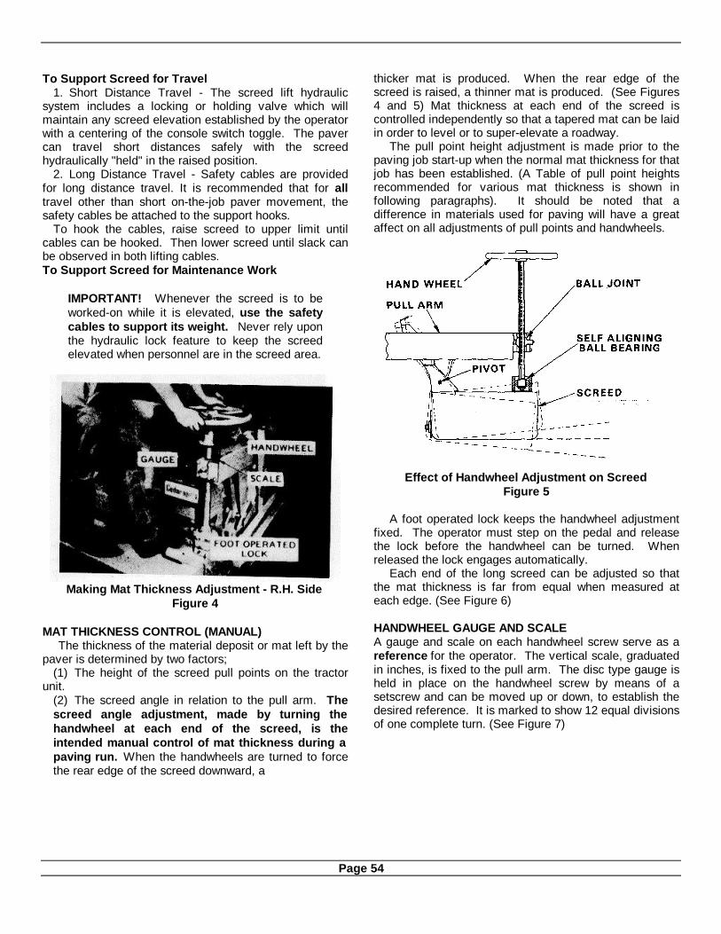
To Support Screed for Travel1. Short Distance Travel - The screed lift hydraulic
system includes a locking or holding valve which willmaintain any screed elevation established by the operatorwith a centering of the console switch toggle. The pavercan travel short distances safely with the screedhydraulically "held" in the raised position.
2. Long Distance Travel - Safety cables are providedfor long distance travel. It is recommended that for alltravel other than short on-the-job paver movement, thesafety cables be attached to the support hooks.
To hook the cables, raise screed to upper limit untilcables can be hooked. Then lower screed until slack canbe observed in both lifting cables.To Support Screed for Maintenance Work
IMPORTANT! Whenever the screed is to beworked-on while it is elevated, use the safetycables to support its weight. Never rely uponthe hydraulic lock feature to keep the screedelevated when personnel are in the screed area.
Making Mat Thickness Adjustment - R.H. SideFigure 4
MAT THICKNESS CONTROL (MANUAL)The thickness of the material deposit or mat left by the
paver is determined by two factors;(1) The height of the screed pull points on the tractor
unit.(2) The screed angle in relation to the pull arm. Thescreed angle adjustment, made by turning thehandwheel at each end of the screed, is theintended manual control of mat thickness during apaving run. When the handwheels are turned to forcethe rear edge of the screed downward, a
thicker mat is produced. When the rear edge of thescreed is raised, a thinner mat is produced. (See Figures4 and 5) Mat thickness at each end of the screed iscontrolled independently so that a tapered mat can be laidin order to level or to super-elevate a roadway.
The pull point height adjustment is made prior to thepaving job start-up when the normal mat thickness for thatjob has been established. (A Table of pull point heightsrecommended for various mat thickness is shown infollowing paragraphs). It should be noted that adifference in materials used for paving will have a greataffect on all adjustments of pull points and handwheels.
Effect of Handwheel Adjustment on ScreedFigure 5
A foot operated lock keeps the handwheel adjustmentfixed. The operator must step on the pedal and releasethe lock before the handwheel can be turned. Whenreleased the lock engages automatically.
Each end of the long screed can be adjusted so thatthe mat thickness is far from equal when measured ateach edge. (See Figure 6)
HANDWHEEL GAUGE AND SCALEA gauge and scale on each handwheel screw serve as areference for the operator. The vertical scale, graduatedin inches, is fixed to the pull arm. The disc type gauge isheld in place on the handwheel screw by means of asetscrew and can be moved up or down, to establish thedesired reference. It is marked to show 12 equal divisionsof one complete turn. (See Figure 7)
Page 54

Handwheels Set to Level Inclined RoadwayFigure 6
The scale is graduated vertically from a centralzero marking. The graduations may be in inches, withincrements of 1/4¼", 3" each way from the zero, sothat the total range is 6". Or the graduations may bein turns of the handwheel, with increments of 1 turn,12 turns each way from zero, so that the total range is24 turns.
The disc-like gauge which is attached to thehandwheel screw has 12 equally space markingswhich can be indexed from the edge of the verticalscale to show the division of 1 turn.
The scale reading is taken by holding a smallstraight edge upward against the bottom of the gaugedisc and across the scale face.
When an operator has established the best handwheel setting for paving a specific thickness with aspecific material, he will zero the two gauge and scalereadings then tighten the gauge setscrews. He thenmakes a record of the conditions and gauge settingsfor future reference. Whenever a new pav-
ing job is to be started, or when an extensivethickness change is to be made on a job, the operatorcan adjust the handwheels to the reference marks andstart-off very close to the mat thickness desired, if hehas recorded reference close to the new requirement.Without a reference he must guess at the setting andmake corrections on the first several feet of the newmat. Eventually an operator's reference record willcover most of the common mat thicknesses and typesof material used
Change of material specifications will usuallycause a different screed behavior and a differenthandwheel setting, even though the mat thickness is acommon one.
To obtain a smooth mat, the screed adjustmentcontrols should be gradually changed, one notch at atime, and the screed should travel a few feet beforean additional adjustment is made. This will allowthe screed the proper distance of travel required toseek the new level of operation.
Screed Man Making Handwheel AdjustmentFigure 8
Page 55
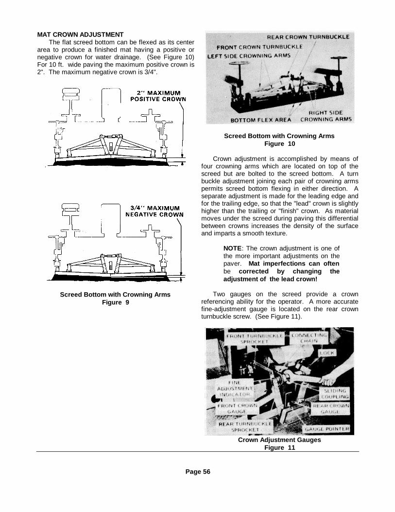
MAT CROWN ADJUSTMENTThe flat screed bottom can be flexed as its center
area to produce a finished mat having a positive ornegative crown for water drainage. (See Figure 10)For 10 ft. wide paving the maximum positive crown is2". The maximum negative crown is 3/4".
Screed Bottom with Crowning ArmsFigure 9
Screed Bottom with Crowning ArmsFigure 10
Crown adjustment is accomplished by means offour crowning arms which are located on top of thescreed but are bolted to the screed bottom. A turnbuckle adjustment joining each pair of crowning armspermits screed bottom flexing in either direction. Aseparate adjustment is made for the leading edge andfor the trailing edge, so that the "lead" crown is slightlyhigher than the trailing or "finish" crown. As materialmoves under the screed during paving this differentialbetween crowns increases the density of the surfaceand imparts a smooth texture.
NOTE: The crown adjustment is one ofthe more important adjustments on thepaver. Mat imperfections can oftenbe corrected by changing theadjustment of the lead crown!
Two gauges on the screed provide a crownreferencing ability for the operator. A more accuratefine-adjustment gauge is located on the rear crownturnbuckle screw. (See Figure 11).
Crown Adjustment GaugesFigure 11
Page 56
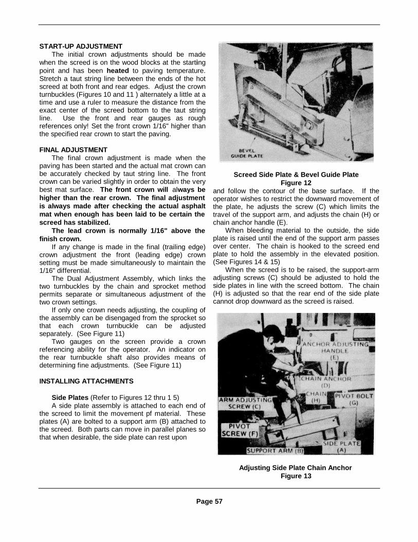
START-UP ADJUSTMENTThe initial crown adjustments should be made
when the screed is on the wood blocks at the startingpoint and has been heated to paving temperature.Stretch a taut string line between the ends of the hotscreed at both front and rear edges. Adjust the crownturnbuckles (Figures 10 and 11 ) alternately a little at atime and use a ruler to measure the distance from theexact center of the screed bottom to the taut stringline. Use the front and rear gauges as roughreferences only! Set the front crown 1/16" higher thanthe specified rear crown to start the paving.
FINAL ADJUSTMENTThe final crown adjustment is made when the
paving has been started and the actual mat crown canbe accurately checked by taut string line. The frontcrown can be varied slightly in order to obtain the verybest mat surface. The front crown will always behigher than the rear crown. The final adjustmentis always made after checking the actual asphaltmat when enough has been laid to be certain thescreed has stabilized.
The lead crown is normally 1/16" above thefinish crown.
If any change is made in the final (trailing edge)crown adjustment the front (leading edge) crownsetting must be made simultaneously to maintain the1/16" differential.
The Dual Adjustment Assembly, which links thetwo turnbuckles by the chain and sprocket methodpermits separate or simultaneous adjustment of thetwo crown settings. If only one crown needs adjusting, the coupling ofthe assembly can be disengaged from the sprocket sothat each crown turnbuckle can be adjustedseparately. (See Figure 11)
Two gauges on the screen provide a crownreferencing ability for the operator. An indicator onthe rear turnbuckle shaft also provides means ofdetermining fine adjustments. (See Figure 11)
INSTALLING ATTACHMENTS
Side Plates (Refer to Figures 12 thru 1 5)A side plate assembly is attached to each end of
the screed to limit the movement pf material. Theseplates (A) are bolted to a support arm (B) attached tothe screed. Both parts can move in parallel planes sothat when desirable, the side plate can rest upon
Screed Side Plate & Bevel Guide PlateFigure 12
and follow the contour of the base surface. If theoperator wishes to restrict the downward movement ofthe plate, he adjusts the screw (C) which limits thetravel of the support arm, and adjusts the chain (H) orchain anchor handle (E).
When bleeding material to the outside, the sideplate is raised until the end of the support arm passesover center. The chain is hooked to the screed endplate to hold the assembly in the elevated position.(See Figures 14 & 15)
When the screed is to be raised, the support-armadjusting screws (C) should be adjusted to hold theside plates in line with the screed bottom. The chain(H) is adjusted so that the rear end of the side platecannot drop downward as the screed is raised.
Adjusting Side Plate Chain AnchorFigure 13
Page 57

Swinging Side Plate to Vertical Position& Anchoring to Permit Material Bleeding
Figure 14
Method of Attaching Chain for BleedingFigure 15
Bevel Guide Plates (Refer to Figure 12)Bevel guide plates can be bolted to the side plates
in order to produce a beveled edge on the mat as thematerial is deposited. The degree of bevel is 450°. Thebevel depths available are 1½ /2" and 3".
Retaining PlatesMaterial retaining plates must be used ahead of
extended screw conveyors whenever the matextension exceeds 2 ft. These plates prevent theforward spread of material so that the screws arehandling a uniform depth all the way out to the ends(See Section 6, Figures 10 & 11). When up to 4 ft. ofextension is added to one end of the screed aretaining plate support angle is attached to the screedpull arm and when the number of plates ex-
Typical 36” Retaining Plate ArrangementFigure 16
Disengaging Coupling to Stop Screw End SectionFigure 17
ceeds two, an extra brace is added. (See Figure 16).
Cut-off Shoes (Refer to Figure 18)Standard cut-off shoes which fit the paver
extensions reduce the paving width in varyingamounts in 112" increments, down to the minimum of10 ft. They slide under the side plates and are boltedin place. Bolt holes are spaced 1 /2" apart.
(1) To install cut-off shoe, block up screed toshoeheight.(2) Raise side plate and slide cut-off shoe "G" underscreed as much as required for desired mat widthreduction. (See Figure 19)(3) Bolt cut-off shoe to side plate. (Shoe fits eitherend of screed.)(4) Release lock (J) on spreader screw to allow tipscrew section (H) to become idle. To prevent materialfrom being fed onto the top of the cut-off shoe andspilling onto the road base, fashion pieces
Page 58
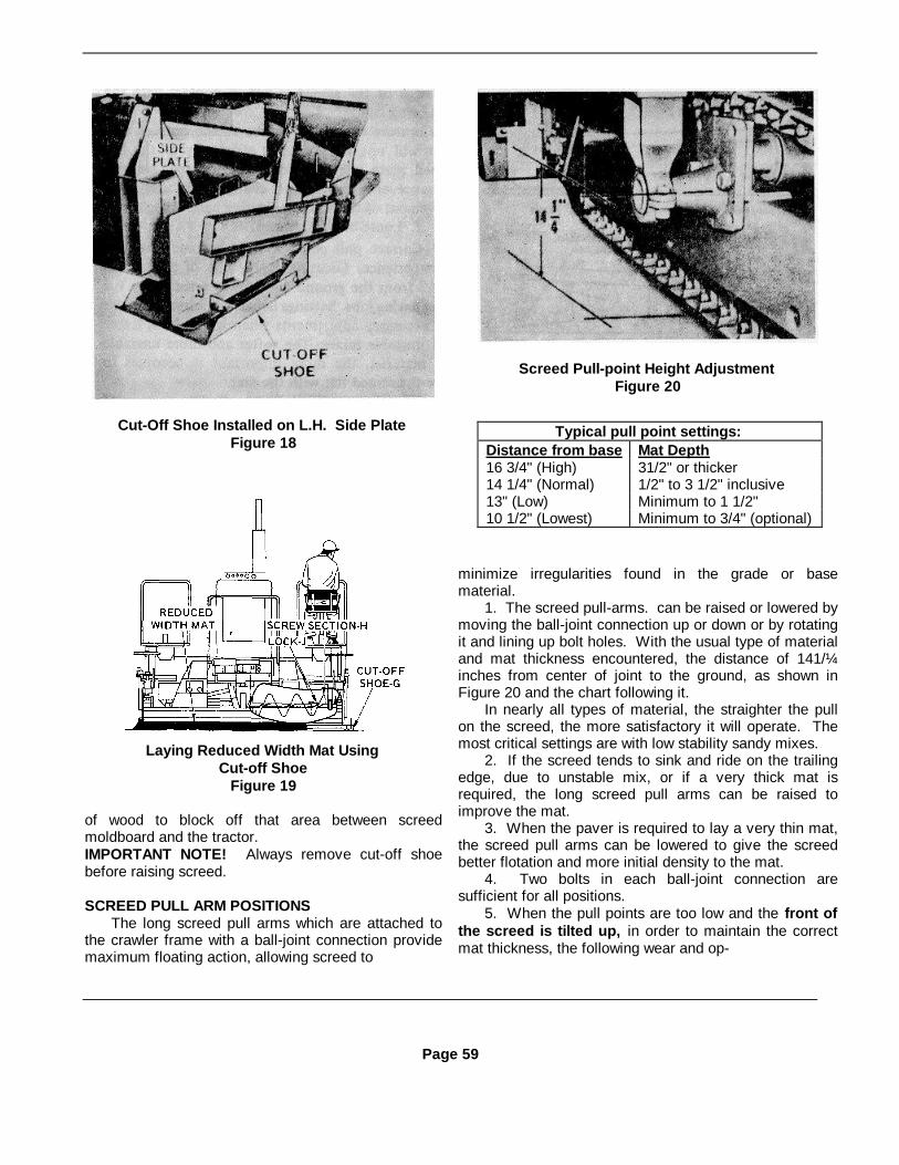
Cut-Off Shoe Installed on L.H. Side PlateFigure 18
Laying Reduced Width Mat UsingCut-off Shoe
Figure 19
of wood to block off that area between screedmoldboard and the tractor.IMPORTANT NOTE! Always remove cut-off shoebefore raising screed.
SCREED PULL ARM POSITIONSThe long screed pull arms which are attached to
the crawler frame with a ball-joint connection providemaximum floating action, allowing screed to
Screed Pull-point Height AdjustmentFigure 20
minimize irregularities found in the grade or basematerial.
1. The screed pull-arms. can be raised or lowered bymoving the ball-joint connection up or down or by rotatingit and lining up bolt holes. With the usual type of materialand mat thickness encountered, the distance of 141/¼inches from center of joint to the ground, as shown inFigure 20 and the chart following it.
In nearly all types of material, the straighter the pullon the screed, the more satisfactory it will operate. Themost critical settings are with low stability sandy mixes.
2. If the screed tends to sink and ride on the trailingedge, due to unstable mix, or if a very thick mat isrequired, the long screed pull arms can be raised toimprove the mat.
3. When the paver is required to lay a very thin mat,the screed pull arms can be lowered to give the screedbetter flotation and more initial density to the mat.
4. Two bolts in each ball-joint connection aresufficient for all positions.
5. When the pull points are too low and the front ofthe screed is tilted up, in order to maintain the correctmat thickness, the following wear and op-
Page 59
Typical pull point settings:Distance from base Mat Depth16 3/4" (High) 31/2" or thicker14 1/4" (Normal) 1/2" to 3 1/2" inclusive13" (Low) Minimum to 1 1/2"10 1/2" (Lowest) Minimum to 3/4" (optional)

Effect of Pull-point Height on Screed WearFigure 21
erational difficulties will be encountered.a. Premature wear on the trailing edge of the thescreed.b. A tendency for the screed to climb each time thepaver starts with normal hand wheel setting. Poorcontrol of mat thickness will exist and good transversejoints will be difficult' to make.c. Possible tearing of the mat because of excessiveironing effect of the screed.d. Loose or worn screed.6. When the pull points are too high and the front ofthe screed is tilted down, in order to maintain thecorrect mat thickness, the following wear andoperational difficulties will be encountered.a. Premature wear on the leading edge of screed andpossibly deformation of the strike-offs because of theexcessive pressures exerted against it when operatingin this manner.b. Bumpy, wavy road caused by the screed riding onits leading edge.c. Tendency for screed to dip each time the paverstarts with normal hand wheel setting.d. Tearing the mat, caused by the "digging in" actionof screed.e. Loss of compaction will result as the trail-
ing edge of the screed is not in contact with the matbeing laid.
Vibrators connected to the screed bottom supportwill not be operating efficiently as the full screed platewidth is not being utilized. Mat appearance andtexture will change with only slight movement of thescreed adjusting hand wheels.
f. Loose or worn screed.7. Correct pull point settings become a matter of
experience. Locating center line of pull points 14 1/4"from the ground has proven satisfactory for mostpaving jobs. Settings listed will normally cover thenecessary adjustments when laying both stable andunstable mixes. The softer and more unstable thematerial, the more important it becomes to have thescreed flat with the mat.
NOTE: Unstable mixes can be causedby too much asphalt in the mix, poorgradation, poor quality asphalt,excessive temperature, moisture in thematerial and insufficient dust.IMPORTANT: Both pull points must belocated equal distance from the ground.
Flat Strike-off Installed on ScreedFigure 22
STRIKE-OFFThe strike-off located ahead of the screed plate, is
a metering, pre-compactor, and pre-screeding device,that when properly positioned provides the exactamount of material to the screed. It also absorbs wearwhich would otherwise take place on the leading edgeof the screed bottom. If this strike-off is not properlyadjusted and maintained, it can cause operationaldifficulties.
Page 60

Checking Height of Flat Strike-offFigure 23
Adjusting Height of Strike-offFigure 24
ZEROING AND ADJUSTING STRIKE-OFFS
1. After strike-offs are properly assembled tosereed. lower strike-offs until flush with screedbottom. Use the template straight edge to checkposition of strike-offs. See Figure 23.
2. Then, adjust gauges to "0" setting with gaugepointers.
3. Raise strike-offs above screed bottomaccording to the chart. (Shown below.) Make the finalad-
justment for the mat texture while paving. Neverlower strike-offs below screed bottom. Important!Always make strike-off adjustments when screedand asphalt are hot. If the asphalt is cold,adjusting bolts and brackets will bend before thestrike-off moves and the entire adjustmentassembly is damaged.
4. Whenever strike-offs are to be re-adjusted, it isbest to lower both sides, then use the top adjusting nutat each of the four adjustment points to pull the strike-offs up to the desired gauge readings. This is auniform movement of the strike-offs and
Cross-section - Flat Strike-off AssemblyFigure 25
Height ofFlat Strike-off Characteristics of Asphalt
"+1/16" Standard (Normal Mat Conditions)1/4" Aggregate Size; Sand to 1" Minus Aggregate- 0" Mat Thickness: 1¼" to Maximum Thickness
Alternate (Fines Materials with Thin Mat)3/16" + 1/16" Aggregate Size: Fines to 1/4" minus sand
Mat Thickness: Minimum 1/2" to 1" mat3/8" + 1/8" **Alternate (Coarse Materials with Thick Mat)3/8" *Aggregate Size: 1" minus 1½ ” maximum Recommended__- 1/16" Mat Thickness: 2" to maximum thickness
*Pavers have laid top size material of 3" minus, however accelerated wear can be expected.**Only if tearing due to flats in aggregate. With flat plate strike-off it is possible to raise to 1½ ",there-fore, no strike-off effect.
Page 61

Flat Strike-off Adjusted Too LowFigure 26
RESULTS OF IMPROPER STRIKE-OFFWhen the strike-offs are too low the following wearand operational difficulties will be encountered. (SeeFigure 26).
1. Insufficient amount of material will be meteredto the screed. Therefore, in order to maintain matthickness, it is necessary to tip the front of the screedup. Continued operation of the screed in this mannermay cause wear on the trailing edge of the screed.
2. Fines will collect at the front edge of the screeddirectly behind the strike-offs which will build up andcause tearing and voids in the mat. The strike-off willfrequently catch and drag large stone, with the resultthat a streak is made in the mat. When this occursoften, stop paving, raise the strike-off, and try again.When the strike-offs are too high the following wearand operational difficulties will be encountered. (SeeFigure 27).
1. Too much material will be metered to thescreed. Therefore, in order to maintain a relativelythin mat thickness, it is necessary to tip the front of thescreed down with the hand wheel adjustments. Withthe screed in this position for any length of time, rapidwear on the leading edge of the screed will occur.
2. Poor mat textures and low compaction of themat will prevail under these conditions.
3. Erratic control of the screed will be noticeablewhen making minor adjustments.
Flat Strike -off Adjusted Too HighFigure 27
Paving With Extended ScreedFigure 28
EXTENSION OF SCREEDThe screed length can be extended in order to lay amat wider than 10 ft. Mat widths up to and including20 ft. can be laid. Screed extensions come in variouswidths and can be attached to either end of thescreed.Each 6", 12" and 24" extension is supplied completewith cover, moldboard extension, and adjustablestrike-off extension.
12 Inch Extension On LH End Of ScreedFigure 29
All parts of the extension are shipped loose andmust be assembled in the field. Some careful work isrequired to align each extension bottom to the screedbottom, the moldboard extension to the moldboard,and the strike-off plate extension to the strike-offplate.
A double set of shim packs is supplied with eachextension so that an adjusted shim pack can be keptinside the extension at its proper corner location.(See Figure 30). The lengthy job of fitting theextension bottom to the screed bottom need notbe repeated each time the extensions areinstalled. Re-installation of the two correct shimpacks will quickly restore alignment and no time islost. The moldboard shims can also be attached attheir respective locations to save time aligning theextension moldboard.
A step by step procedure for assembly andinstallation of an extension is shown on the followingpages.
Page 62

ASSEMBLY OF SCREED EXTENSION
1. Run a ½ " NC tap through the screw holes forstrike-off plate to clean out paint and dirt.(The special screws are not locally available.)
2. Install the Support. Tighten the two flat-head* socket screws.
3. Install the Bracket and the Height Gauge.
4. Install a Gauge Pointer on each of the twoAdjusting Bolts.
5. Install the two Adjusting Bolt assembliesusing* a hex nut above the bracket and one below.
6. Run a ½ /2" NC tap through the screw hole ineach Adjusting Bolt assembly to clean outpaint and dirt.
7. Install the Strike-Off Plate using all of thespecial parts shown in Illustration 8, arrangedexactly as shown! Tighten Shoulder Screws.
8. Arrange the Seal and the three Washers oneach Shoulder Screw as shown above
Page 63
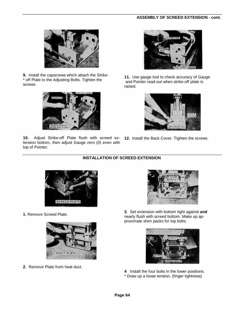
ASSEMBLY OF SCREED EXTENSION - cont.
9. Install the capscrews which attach the Strike-* off Plate to the Adjusting Bolts. Tighten thescrews.
10. Adjust Strike-off Plate flush with screed ex-tension bottom, then adjust Gauge zero (0) even withtop of Pointer.
11. Use gauge tool to check accuracy of Gauge and Pointer read-out when strike-off plate israised.
12. Install the Back Cover. Tighten the screws.
INSTALLATION OF SCREED EXTENSION
1. Remove Screed Plate.
2. Remove Plate from heat duct.
3. Set extension with bottom tight against andnearly flush with screed bottom. Make up ap-proximate shim packs for top bolts.
4 Install the four bolts in the lower positions.* Draw up a loose tension. (finger tightness)
Page 64

INSTALLATION OF SCREED EXTENSION - Continued
5 Suspend screed on its safety cables. Checkacross the two bottom surfaces with straightedge to align flush.
6. Adjust the two shim packs to align the bottomsurfaces and draw all six bolts very tight. Recheckalignment.
7. Re-check alignment.
8 Fit Moldboard Extension into place betweenstrike-off plate and extension.
9. Install bolts and tubular spacers.
10. Add shims at all top bolt positions as necessary* to align the moldboard and the moldboardextension. Tighten all three bolts.
11. Use a straight edge and adjust the extentionstrike-off plate exactly in line with the adjacentstrike-off plate
12 Install the Heat Duct Deflector whenever anextension longer than 1 foot is added. For 1 footextension leave duct cover plate off.
Page 65

INSTALLATION OF SCREED EXTENSION - Continued
13. Install screed plate. Use hex head screws at rearand flat head screws at front, where the side platerequires clearance
14. Install the extension cover
Extension With Adjusted Shim Packs AttachedFigure 30
IMPORTANT! When extensions are removed from the screed always attach the correct shim pack at thecorrect point of use so that you will nlot have to delay the job by re-figuring the two packs. Merely use theformer shim pack and the alignment will be correct. (See Figure 30).
When more than one extension is used at one end of the screed, be sure to mark each extension for re-installation in the same order as before. Mark the extension attached to the screed as No. 1, the second fromthe screed, No. 2, etc. This will keep the adjusted shim packs correct for straight bottom alignment.
The bottom of an outer extension should be checked for wear frequently particularly when over lap pavingis done. An extension is always recommended for use at the point of overlap so that the short length ofbottom section will absorb the extra wearing tendency of the overlap operation.
Page 66

Cut-away Of Screed Showing Heating SystemFigure 31
Cross-section Showing Heat Flow Thru ScreedFigure 32
SCREED HEATERThe fuel oil or LP gas fired screed heating system is switch operated at the burner unit. Fuel ignition is
automatic and fan operation is continuous. The fan forces the hot fumes of combustion downward through theflame chamber and into a distributor duct which extends to each end of the screed. The heat passes across theentire screed bottom surface, then travels upward through the curved hollow moldboard assembly to ventsalong its upper edge.(See Figures 31 and 32).
The main purpose of the heater is to raise the temperature of a cold screed to approximately 3000 F.before first contact with the hot asphalt mix. This assures a non-sticking flow of material along the moldboardand screed bottom and imparts a smoother more uniform mat surface texture. When paving begins the heateris usually shut off, as the hot asphalt material will normally maintain the proper screed temperature.
If material delivered to the paver hopper has cooled too much, the surface texture of the mat may beimproved by running the screed heater. The excessive cooling of material may be caused by delays in hauling,however, if the material was dumped into the truck at too low a temperature a correction must be made at themixing plant to restore efficient production of a high quality mat.
The temperature recommended for material delivered to the paver is 2500 F. minimum when medium andhigh penetration asphalt is used. The minimum is 3000 F. for low penetration (40 to 50) asphalts. Many matdefects can be caused by incorrect material temperature at the time of paving.
Usually a screed bottom will be heated sufficiently by running the heater for 20 to 30 minutes. When thescreed is hot enough, close the burner fuel valve but leave the switch at ON to keep the blower motor runningfor at least 15 minutes to dissipate the heat. On oil fired units also open the vent door at the top to speed thecooling. Excessive heat can cause the screed to warp. Do Not Heat the Screed Above 3500°!
IMPORTANT: When specifications require heat on the material at all times theheater should be set as low as possible.
A check for accumulation of asphalt in the heat vent holes the moldboard can be made by placing a handnear these openings behind the top of the moldboard and checking the full length for even exhaust of warm air.These vents become plugged when material is carried too high over the conveyor screws and falls between themoldboard and backing plate. A stiff wire can be used to clean small accumulations of material, or themoldboard can be removed for cleaning.
Periodically remove the screed plate as described in the Maintenance Section 11 and clean the inside ofthe screed plate and heat duct of all asphalt, sand the fine material which has sifted in over a period of time.Failure to keep the inside of screed plate clean will cause uneven distribution of heat to a cold screed andconsequently lead to tearing of the mat surface when the paving operation begins.
Page 67
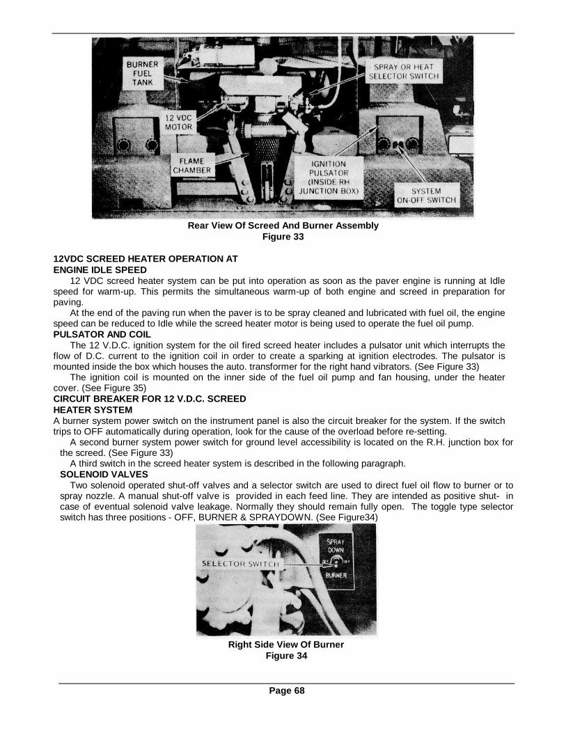
Rear View Of Screed And Burner AssemblyFigure 33
12VDC SCREED HEATER OPERATION ATENGINE IDLE SPEED
12 VDC screed heater system can be put into operation as soon as the paver engine is running at Idlespeed for warm-up. This permits the simultaneous warm-up of both engine and screed in preparation forpaving.
At the end of the paving run when the paver is to be spray cleaned and lubricated with fuel oil, the enginespeed can be reduced to Idle while the screed heater motor is being used to operate the fuel oil pump.PULSATOR AND COIL
The 12 V.D.C. ignition system for the oil fired screed heater includes a pulsator unit which interrupts theflow of D.C. current to the ignition coil in order to create a sparking at ignition electrodes. The pulsator ismounted inside the box which houses the auto. transformer for the right hand vibrators. (See Figure 33)
The ignition coil is mounted on the inner side of the fuel oil pump and fan housing, under the heatercover. (See Figure 35)CIRCUIT BREAKER FOR 12 V.D.C. SCREEDHEATER SYSTEMA burner system power switch on the instrument panel is also the circuit breaker for the system. If the switchtrips to OFF automatically during operation, look for the cause of the overload before re-setting.
A second burner system power switch for ground level accessibility is located on the R.H. junction box forthe screed. (See Figure 33)
A third switch in the screed heater system is described in the following paragraph.SOLENOID VALVES
Two solenoid operated shut-off valves and a selector switch are used to direct fuel oil flow to burner or tospray nozzle. A manual shut-off valve is provided in each feed line. They are intended as positive shut- incase of eventual solenoid valve leakage. Normally they should remain fully open. The toggle type selectorswitch has three positions - OFF, BURNER & SPRAYDOWN. (See Figure34)
Right Side View Of BurnerFigure 34
Page 68

Exploded View of Screed HeaterFigure 35
TO OPERATE SCREED HEATER (OIL FIRED)1. Set engine operation at idle speed.2. Close air vent cover & adjustable air damper.3. Open the supply tank valve. (If closed)4. Open burner feed valve. (If closed)5. Set solenoid selector switch to BURNER.6. Push burner switch to ON (*) at instrument panel. Turn junction box burner switch to ON.7. Check sight hole in flame chamber for flame.8. Adjust air damper on burner to obtain bright, clean fire. (Approximately 1/3 to 1/2 open.)
To Turn Burner Off1. Set solenoid selector switch to OFF.2. Open air vent cover.3. Run burner blower for approximately 15 minutes or until fumes and heat are dissipated in screed.4. Turn junction box burner switch to OFF (*). Pull instrument panel switch to OFF.5. Close air vent cover at end of day's run to prevent moisture from entering screed.(*) NOTE: Burner will re-light quicker when switch has been at "OFF' for two or three minutes, and air
damper is closed.
Burner Nozzle & Ignition ElectrodesFigure 36
To Use Spray Hose1. Run engine at idle speed.2. Open supply tank valve. (If closed)3. Open spray hose valve. (If closed)4. Set solenoid selector switch to Spray Down.5. Push burner switch ON at instrument panel.6. Turn junction box burner switch to ON.
Page 69

Top View of Screed Junction BoxFigure 37
Trouble and Remedies for Oil Burner
1. No Oil Spray and No Ignition(a) Check instrument panel switch for ON. It is also the system circuit breaker and may have tripped
immediately by an overload.(b) Check junction box burner switch for ON.(c) Check solenoid valve selector switch (located close to valves on RH side of burner). It has three
positions, BURNER-OFF-SPRAY DOWN.(d) Check wiring to switches. There should be 12 volts DC at the power terminal. (Refer to electrical
trouble shooting data in Section 4.)
2. Oil Spray but No Ignition(a) Turn burner switch to OFF.(b) Remove burner cover and check for contact of ignition coil wire to electrode contact strip.(c) Remove electrode assembly. Clean electrode points and insulator and determine if insulator is cracked
or broken. Check setting of electrode points to specifications in Figure 35.(d) Check wiring from switch to pulsator and from pulsator to coil. (Refer to Electrical Section 4.)(e) Re-install electrode assembly in burner. Install cover. Turn burner switch to ON. If there is still no
ignition, check pulsator. (Refer to Burner Electrical System Troubleshooting Instructions in Section 4.)
3. Ignition but No Spray from Burner Nozzle(a) Be sure hand valve in burner fuel line is open.(b) Check fuel oil tank for level. Be sure sediment filter element is not plugged.(c) Turn burner switch ON and make sure fan is running. Turn solenoid selector switch to SPRAY DOWN
and squeeze spray nozzle lever to see if normal spraying occurs. (Be sure hand valve in hose line isopen.)
(d) If normal spraying occurs turn switch to BURNER and check at burner solenoid wire terminals for 12VDC with voltmeter. If no voltage, the toggle switch or wiring is faulty.
(e) If 12 VDC is present, turn switch to OFF. Disconnect burner fuel line at shut-off valve. Hold a containerin such a way that a spurt of oil can be safely caught. With pump running, jog switch to BURNERposition. If no oil spurts into container, solenoid valve is inoperative.
(f) If oil spurts from valve, re-connect fuel line. Clean burner nozzle and the strainer ahead of it.
Note: Pump must develop 100 PSI pressure in feed line for proper operation.Replace pump if gauge installed in feed line does not show 100 PSI.
Page 70

SCREED VIBRATORSThe electric vibrators on the screed which help with the initial compaction and smoothing of a high density
mat are operated by toggle switch
Figure 38 Adjusting Screed Vibrator Intensityfrom the control console. The vibrators will only operate when the paver is at full throttle and eitherTrack Switch is in the Travel position . This prevents extra compaction in one place on the mat when thepaver is temporarily stopped. (Note: Vibrators can be test-operated when paver is not moving by first movingthe clutch lever on the side of the engine housing to DISENGAGED position. Transmission must be inFORWARD.) The operating intensity of each unit can be varied to produce more or less vibration. Anadjusting knob is located on the variable transformer connected to each vibrator (See Figure 38). Arecommended start-up setting is 3/4 of the range between zero and the highest dial marking.SCREED MAINTENANCE
It is important that the screed be kept in good condition so that wear, looseness, or breakage of parts doesnot begin to produce poor paving results before a noticeable defect exists. The hand wheel assemblies whichadjust the screed angle must be kept in good condition. Crown adjustment and spring hanger bolts must bekept tight. There are numerous places where wear can be compensated by shimming and adjusting. SeeMaintenance Section 11 for details.
Screed Bottom With Crowning And Pull ArmsFigure 39
QUICK-CHANGE SCREED BOTTOM:The asphalt finishing surface of the full floating screed should be kept in good condition. The quickchange
bottom features makes replacement of this vital part relatively easy. If all paving is done with the correctadjustment of the pull arm "pull-point" and strike-off, and without extensive bridging when mat overlap isrequired, the screed bottom will wear uniformly.
If either the leading or trailing edge does wear first, the bottom can be reversed to interchange the leadingand trailing edges.
Always replace the screed bottom before it wears completely through!
Quick-change Screed Bottom With Frame And Crowning ArmsFigure 40Page 71
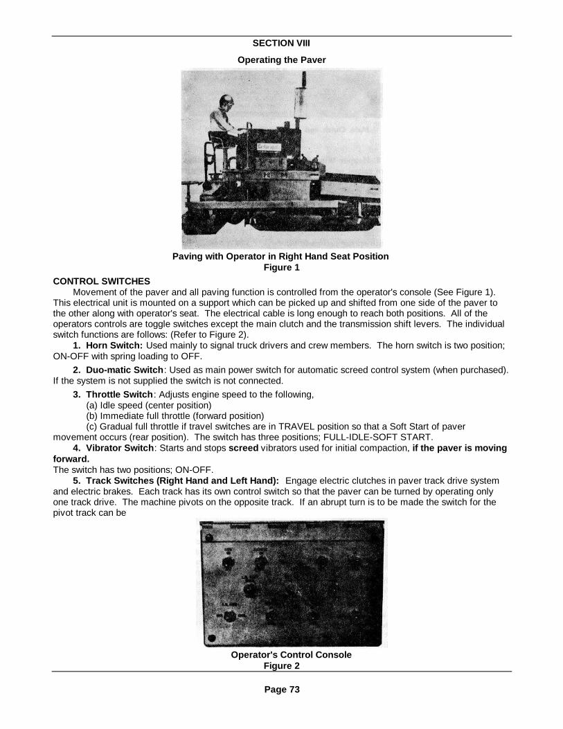
SECTION VIII
Operating the Paver
Paving with Operator in Right Hand Seat PositionFigure 1
CONTROL SWITCHESMovement of the paver and all paving function is controlled from the operator's console (See Figure 1).
This electrical unit is mounted on a support which can be picked up and shifted from one side of the paver tothe other along with operator's seat. The electrical cable is long enough to reach both positions. All of theoperators controls are toggle switches except the main clutch and the transmission shift levers. The individualswitch functions are follows: (Refer to Figure 2).
1. Horn Switch: Used mainly to signal truck drivers and crew members. The horn switch is two position;ON-OFF with spring loading to OFF.
2. Duo-matic Switch: Used as main power switch for automatic screed control system (when purchased).If the system is not supplied the switch is not connected.
3. Throttle Switch: Adjusts engine speed to the following,(a) Idle speed (center position)(b) Immediate full throttle (forward position)(c) Gradual full throttle if travel switches are in TRAVEL position so that a Soft Start of paver
movement occurs (rear position). The switch has three positions; FULL-IDLE-SOFT START.4. Vibrator Switch: Starts and stops screed vibrators used for initial compaction, if the paver is moving
forward.The switch has two positions; ON-OFF.
5. Track Switches (Right Hand and Left Hand): Engage electric clutches in paver track drive systemand electric brakes. Each track has its own control switch so that the paver can be turned by operating onlyone track drive. The machine pivots on the opposite track. If an abrupt turn is to be made the switch for thepivot track can be
Operator's Control ConsoleFigure 2
Page 73

moved to the BRAKE position and the paver turns sharply. If both switches are moved to the BRAKE positionthe paver stops instantly. In its center position the switch is OFF. Each switch has three positions: TRAVEL-OFF-BRAKE.
6. Screed Lift Switch: Raises, holds, or lowers screed assembly by hydraulic power. In the centerposition, the screed position is held hydraulically locked so that no downward creep can occur. The switch isthree position; UP-HOLD-DOWN with spring return to HOLD.
7. Feed Switches (Right and Left Hand): These two switches individually start and stop each pair ofcombined slat and screw conveyors which feed material ahead of each half of the screed. Conveyor operationcan be controlled manually with the operator observing the amount of feed, or it can be done automaticallyusing two auxiliary "feeler switches" which are operated by material build-up near the ends of the screws. Eachtype of operation engages or dis-engages the electric clutches which drive the conveyors. Each switch hasthree positions; MANUAL-OFF-AUTOMATIC.
Adjustable Material Depth Control Switchwith Feeler Arm - R.H. Assembly Shown
Figure 3NOTE: The conveyors will not run unless the paver transmission shift lever for travel direction .is in theFORWARD position. (See Figure 4) A limit switch actuated by the transmission opens the conveyor electricalcircuit when the paver is shifted for reverse travel.
Main Clutch and Transmission Shift LeversFigure 4
8. Hopper Wing Switch: The two hopper wings are raised or lowered by operation of this toggle switch. Itcontrols valves in the hydraulic system which direct the action of two hydraulic cylinders connected to thewings. The wings are raised when material at the sides of the hopper needs to be moved toward the slatconveyors. The switch is three-position; UP-OFF-DOWN, with spring return to off.
(NOTE: The movement of hopper wings is normally irregular because a single hydraulic pressure linepowers both cylinders and the wing offering the least resistance moves first).
9. Truck Hook Switch: Used as control switch for hydraulically powered truck hook system (when purchased).If system is not supplied the switch is not connected.10. Screed Heater Switches:
Three switches are used to control operation of the oil fired screed heater and oil spray-down unit which ismounted on the screed.
The burner pump and fan motor is controlled by the burner power switch and circuit breaker on theinstrument panel, and the ground level burner switch on the screed junction box.
The selection of burner operation or oil spray for clean-up and lubrication is made by setting the 3-positiontoggle switch on the side of the burner housing. The switch has three positions, OFF - BURNER - SPRAYDOWN. It controls two solenoid operated valves in the fuel oil distribution lines.
Page 74

Three small hand-operated shut-off valves in the fuel oil distribution lines are provided as positive shut-offmeans in the event of leakage through solenoid valves, etc. They are normally open.
See Screed Section 7 for screed heating and fuel oil spray details.PRE-START CHECK (DAILY REQUIREMENT)
Before starting a paver for a regular run the operator should check the following details personally.1- Engine oil level. It will be somewhat below hot oil level, (Dipstick gauge).2 - Transmission oil level (14" on Dipstick).3 - Engine fuel level.4 - Coolant supply. (Radiator).5 - Hydraulic fluid level (Reservoir sight gauge).6 - Battery water level.7 - Screed Heater fuel level.8 - V-Belt Tightness and condition.9 - Engine air filter condition. (Especially Diesel.)10 - Air Filter Hose for loose clamps or leaks.Before starting a paver for a regular run, the operator should make sure that the following requirements
have been attended to:1 - Oil level in both transfer cases is adequate.2 - Grease fittings have been attended as recommended for daily lubrication requirement.
TO START ENGINE:The following procedure is recommended for start-up of a paver in preparation for a paving run.1 - Disengage main clutch.2 - Turn main control key switch to ON.3 - Set both Track switches to BRAKE. Set all other switches on console to OFF.4 - Start engine by turning and holding the key switch to ON. (Also see Engine Operator's Manual).5 - Check to make sure the transmission oil pump is operating in the following way:
(a) Look at the oil line Sight Glass on the top of the transmission. (Section 3, Fig. 10) With the mainclutch disengaged and the transmission pump not turning the sight glass will be clear, indicating no oil flow.
(b) Engage the Main Clutch.(c) Look at the sight glass to be sure it is darkened by the oil flow which indicates that the pump is
working properly to lubricate the upper gears and bearings of the transmission.
Selection Plate for 24-Speed TransmissionFigure 5
PAVER TRAVEL (NOT PAVING)With the engine idling and main clutch disengaged;1. Move both Track Switches to BRAKE position, and Follower Switch to OFF position.2. Set the three transmission levers to produce the speed and direction of movement you wish. (If gears
do not mesh, jog main clutch and try again).(a) Range Lever - #1 (slowest) through #4 (fastest).(b) Direction Lever - Forward or Reverse.(c) Speed Lever - #1 (slowest) through #6 (fastest).
3. Engage main clutch.4. If slow movement is desired, as for unloading the paver or moving through a narrow area, leave the
Throttle Switch at idle and move the track switches to TRAVEL. Steer the paver by moving the switch of thepivot track to OFF or BRAKE depending upon how sharp a turn is needed.
5. When fast movement is desired, move the Throttle Switch to SOFT START and move both TrackSwitches to TRAVEL. Steer the paver by moving the switch of the pivot track to OFF or BRAKE depending onhow sharp a turn is needed.
Page 75

STOPPING PAVERA paver is normally stopped by moving both Track Switches to the OFF (center) position. If an emergency
stop is required, move both track switches all the way forward to BRAKE position. CAUTION! An operatorshould be braced for sudden stoppage if brakes are applied when the paver is moving at top speed.PARKING AND HAULING PAVER - IMPORTANT!
When a paver is to be parked on any degree of slope, both tracks should be adequately blocked at thedownhill end to prevent downhill movement! The electric brakes should not be used as parking brakes!When a paver is loaded for transport, regardless of distance to be moved, both tracks must be blockedadequately at each end, or the paver chained down to prevent it from rolling. Do not rely upon the electricbrakes to hold a paver during transit.
ANGULARITY RESTRICTIONSThe constant need for proper engine lubrication makes it necessary to restrict the slope at which the paver
may operate. These restrictions which are imposed by the engine manufacturers are as follows:1. Paving Uphill (See Figure 6) - Do not exceed a 53% slope (28°).2. Paving Downhill (See Figure 7) - Do not exceed a 36%o slope (20°).3. Paving With One End of Screed Elevated (See Figure 8) - Do not exceed a 57% slope (30°).
NOTE: The angularity shown represents the engine operating restriction only! If a paver is to operatenear this slope limitation some satisfactory method of holding the paver on the slope must be devised bythe owner.
CLEANING PAVERIt is important that the paver be thoroughly cleaned at the end of each day's operation. A long spray
nozzle hose is attached to the heater fuel oil supply valve and will reach any part of the paver for spraycleaning and lubricating. (See Figure 9. Refer to Maintenance Section for details.) Every time the paver iscleaned, the tracks should be sprayed with fuel oil. There is enough lubricant in the fuel oil to keep the trackpins from rusting and binding.TIGHTENING NEW TRACKS
IMPORTANT ! A new paver or one having a new set of tracks will require daily tightening of the tracksuntil all link pins have "worn in" and stretching of the track no longer occurs. When this initial stretchingstops it will only be necessary to check and tighten the tracks occasionally. (See Section 11)
Figure 6
Figure 7
Figure 8
Cleaning paver with Screed Heater Fuel Spray AccessoryFigure 9
Page 76

OPERATING CAUTIONWhen a paver has been out of service for a lengthy period, such as during the Winter months, be sure to
clear the hopper of all items such as shovels, tools, and personnel before starting the engine! Undercertain conditions rust will build up on feed clutch surfaces to the extent that slat and screw conveyormovement will take place even when both Feed Switches are OFF. As soon as the rust wears away, operationbecomes normal. Always start the paver after a long shut down with the main clutch disengaged, trackswitches at BRAKE, both Feed Switches OFF, and the hopper cleared.
Main Electrical PanelFigure 10
REVERSING DIRECTION OF SLAT CONVEYOR TO RELIEVE JAMMED OBJECT1. Remove cover of main electrical panel on the front of the engine to expose the paver wiring. (See
Figure 10)2. Connect a jumper wire between terminals No. 45 & No. 46 at any convenient point. (This eliminates
the function of the limit switch on the transmission.)3. Start the engine and run at IDLE speed.4. Shift the transmission Direction Lever to REVERSE. (The limit switch opens but the circuit remains
unbroken due to the jumper wire.)5. Move the appropriate console switch for the conveyor involved to the MANUAL position just long
enough to move the slat conveyor in the reverse direction and release the jammed object. Do not run it longerso that the chain starts to ride-up on the sprockets due to reversed tension. The slat bars can also catch on thereturn rails if the chain happens to be quite slack.
6. Stop the engine. Shut-off all power and remove the jumper wire.VIBRATOR OPERATION WITH PAVER STOPPEDWhenever it is desirable to operate the vibrators when the paver is stationary, proceed as follows:
1. Disengage main clutch.2. Shift transmission into FORWARD gear. (This will close the circuit limit switch.)3. Set engine throttle switch to FULL.4. Set one of the two track switches to TRAVEL.5. Set vibrator switch to ON.
IMPORTANT! When test operating the vibrators, set the screed bottom on a flat surface with nostones or similar objects under it so that the bottom is not scored and scratched as the bottomvibrates.
Page 77

BURNISHING TRACK CLUTCH & BRAKE FACINGS TO IMPROVE PERFORMANCEThe facing material on the two electric track clutches and on the two electric track brake assemblies can
become glazed from operation so that excessive slippage occurs. Poor clutch operation will result in both R.H.& L.H. drives slipping, or in one track consistently failing to keep up with the other so that an abnormal amountof steering is required to maintain a straight course.
Poor brake operation will result in an inability to hold position on uphill paving run.When poor performance of a clutch or brake is suspected, the unit in question should first be 'checked for
armature "hang-up" on the drive pins, oil on the friction faces, improper electrical function, or worn-out frictionfaces. (See details of dimension checking in preceding paragraphs.) Slippage can also be due to an overloadcondition. The drive train and tracks should be inspected for mechanical binding.
If none of the above factors seem to be the cause of clutch slippage, the performance of the clutches maybe improved by carrying out a burnishing operation to remove "glaze" from the friction surfaces. (The sameeffect cannot be obtained by using a solvent, as during an oil removal effort, nor by "roughing-up" the frictionsurfaces by hand!)Burnishing Track Clutches
(1) Move paver to where center of main frame front edge is in direct contact-with a suitable immovableobject, which can safely withstand the full force of paver drive power. IMPORTANT! Be sure that no truck hookor other part of the paver will make contact and be damaged by the full force of the paver drive. The tracksshould be resting on hard dry soil or other dry surface which will not break-up or be badly damaged by the fullforce of the paver drive.
(2) When paver is in place, arrange electric system so that brakes will be on when the Track switches areat the Travel position. (For early model paver brakes the brake coil must be energized. For pavers withelectrically released brakes the coil must be de-energized.)
(3) Arrange track speed controls for high speed travel.(4) Move the track switches to the center position (neutral).(5) Move throttle switch to Full position.(6) Intermittently move one track switch to Travel position then back to neutral so that the clutch is
momentarily engaged and the clutch surfaces heat-up rapidly to above their normal operating temperature.(150 F - approx.).
IMPORTANT! The clutch should not smoke from intense heating.Repeat this procedure on the opposite track. After both clutches have reached the elevated temperature
continue the procedure for at least five minutes at a slower rate so that the temperature is maintained but notexceeded. Both clutches are then burnished at the same time by alternate switch actuation.Burnishing Track Brakes
(1) Arrange track speed controls for high speed travel.(2) With track switches at Brake position, move throttle switch to Full position. When engine is warmed up
for operation move both track switches to Travel and when paver has attained its maximum forward speed,move one track switch to Brake then back to Travel as quickly as possible. When this is done fast enough, thebrake does not "grab", butdoes make sufficient contact to the heat surfaces.
Caution! The operator should however, be braced for sudden deceleration.Repeat this procedure until the brake is hotter than during normal operation (I 500 to 2000 F) but not
smoking. Then repeat the same burnishing effort on the opposite brake.(NOTE: If this procedure presents a problem, the same effect can be obtained by blocking-up the paver
so that both tracks are completely off the ground, and there is no actual paver movement).(3) When the brakes have cooled completely, test paver steering to see that normal operation of the
brakes has been restored.
Page 78

SECTION IX
PLANNING THE PAVING JOB
PLANNING THE PAVING JOBThe careful planning of a paving job is essential to fast, efficient, and low cost operation. Some of the
planning factors related to general paving are covered in the following paragraphs:(a) Material Delivery - The steady delivery of hot material to the paver will often have a bearing on how
a multiple width mat will be divided. The accessibility of roadway to the delivery trucks could possibly overridethe advantages gained by laying portions of the mat in the more desirable way from the standpoint of paveroperation.
(b) Two or More Different Mat Widths - When two or more mats of different widths are laid, the narrowmat which requires the use of a cut-off shoe should be laid first. The final mat can then be laid at full screedwidth without the complication of cut-off parts.
(c) Matching One Mat to Another - When matching one mat to another use a 6" or 1 foot screedextension on the joining end. This will provide a small separate screed bottom surface to absorb the extra wearthat occurs when the slight overlap for matching is made. The extra wear would otherwise take place on onetip of the long screed bottom and destroy its uniformity.
(d) Straight Center Crown Requirement - When it is necessary to maintain a straight crown in themiddle of a wide multiple mat roadway, it is best to lay the crown section first, then match the adjoining mats toit.
(e) Narrow Roadways requiring Multiple Mats When planning to pave a narrow roadway which does nothave a shoulder area for screed overhang past the cut-off shoe, pave the narrow mat first with the screedoverhang on the inside. If this road is to have a crown, the cut-off will be made at the center for both mats withthe shoe actually riding on the first mat when the second mat is laid.
(f) Overlapping Mats - Do not overlap mats extensively unless it is required. If required, keep theoverlap to the minimum requirement. Excessive overlap can cause a bridging and tearing of the mat. If alarge overlap is required use a cut-off shoe to block material from coming too far under the screed in theoverlap area. It is the excess material allowed to build up under a screed that eventually supports the end ofthe screed to cause bridging and holes in the mat. It also causes very rapid wearing of the screed bottom in thearea that is supporting most of the screed weight.
(g) Maximum Stone Size in Material - The intended mat thickness must be at least 11/2 times thedimension of the largest stone size in the material. Fewer problems will be experienced if the mat is twiceor three times thicker than the largest stone dimension.
Example: If the roadway specification calls for a 3" thick rolled mat, the largest stone used in the materialshould not exceed 11/2" to 2"! If 1" stone can be the maximum size it will cause fewer problems than thelarger stone.
Positioning Screed for Paving Start-upFigure 1
PAVING(a) Move the paver into position so that the steering guide marker is aligned and the screed can be
lowered to the exact point at which the mat is to begin. Move both Track Switches to the BRAKE position whenthe paver is in place.
(b) Make a careful check of the screed to make sure it is ready for paving. Extensions, cut-off shoes,etc., should be properly installed. Crown adjustment should be checked with stringline as a start-up setting.Strike-off should be accurately measured and adjusted.
(c) Set wood support blocks under the ends and center of the screed at the correct mat thicknessheight and level for proper screed take-off when paving begins. With engine at full throttle unhook screedsafety cables and lower screed to blocks allowing both lift cables to go completely slack before moving screedlift switch to center (HOLD) position.
(d) Raise each hopper gate to the 1/4 open position for start-up. When paving starts adjust them asnecessary. See Figure 4.
Page 79

(e) For manual adjustment of mat thickness control, turn each handwheel until no load is felt on thescrew. Turn the handwheels clockwise until a load is felt, then turn them an additional 1/3 revolution in thesame direction to set a slight screed angle for start-up.
(f) Make a visual check of engine speed by reading the Frequency Meter. If the engine speed isholding at 2000 RPM the frequency will be steady at 61 cycles (Adjust engine speed governor if necessary toobtain this reading).
(g) Set throttle switch at IDLE and engage the main clutch.(h) With engine at IDLE speed, start screed heater. Heater should run from 20 to 30 minutes in order
to bring the temperature of the screed bottom to approximately 3000 F. CAUTION! Do not heat the screedabove 3500 F as warping can result.
(i) When screed temperature is satisfactory move solenoid valve selector switch to OFF position. Thiswill allow burner fan to dissipate the heat. Also open upper vent door.
(j) When intense heat is eliminated stop fan motor by turning junction box burner switch to OFF.(k) Disengage main clutch.(l) Shift transmission Direction Lever to FORWARD.(m) Shift transmission Range Lever and Speed Lever to produce the paving speed selected. This
selection should be based primarily on the rate at which hot material can be delivered to the paving site. Achart showing paving speeds for 1" mat thickness, as related to tonnage of material required, is shown near theend of this Section. (New operators should use slow speed for gaining first experience).
(n) Set both Track Switches to BRAKE position.When the first truck arrives with material, the paving operation can be started as follows:
(o) Have truck back-up to within 1" (approx.) of the paver push rollers.IMPORTANT! The trucks should never be allowed to bump the paver, as this will cause marks on the
finished mat as paving progresses.
Using Guide Marker, Reference Line and Cut-off ShoeFigure 2
Have the trucker set his brake so that the truck will not roll away from the paver when the material isdumped. IMPORTANT! Do not allow material to be spilled in front of the paver. If this occurs, shovel thespillage into the hopper. Do not attempt to bulldoze it with the front of the paver! Material will jam up thereturn side of the slat conveyors and pack into the track links. If material is left in front of the tracks it maycause waves in the mat.
(p) Dump material Into Paver Hopper.(q) When ready to pave, engage master clutch.(r) Set engine Throttle Switch to FULL position.(s) Move both Feed Switches to the MANUAL position. When the slat conveyors have fed the material
to the spreader screws and it is spread across the full length of the screed to the proper depth, move the FeedSwitches to OFF.
(t) Set Vibrator Switch to ON. (Vibrators will not start until paver moves forward. Adjust the fourVibrator Intensity Control Knobs on the transformers to about 3/4 range to start. When some mat is laid re-adjust the vibrator intensity for the best mat surface appearance. Once properly set, little or no additionaladjustment will be necessary).
(u) Set engine throttle switch to SOFT START position.(v) Set both Track Switches to TRAVEL simultaneously to start paver movement and operate the Feed
Switches manually to keep the material spread ahead of the screed.
Page 80

(w) Correct the direction of paver movement by moving 'the Track Switch of the pivot track to OFFmomentarily.
(x) After some experience is gained with manual feed control, set both Feed Switches to AUTO. andobserve the level of material maintained by the two depth sensors. If necessary, stop paving and re-set eachsensor by loosening the control arm and sliding it inward or outward to maintain a different material height onthe screws.
Adjusting Right Hand Hopper GateFigure 3
MATERIAL CONTROLAdjust hopper gates, Figure 3, so the material flows almost constantly to the spreader screws. The
spreader screws should be kept a little more than half covered with material (Refer to Material Feed,Section 6)
(1) The ends of the spreader screws should not be filled too full. This causes the material to packagainst the end plates and in some cases may spill over the sides. IMPORTANT: When operating withautomatic feed control, never starve the screw conveyors to the extent that there is not enough material inthe screws for the cut-off switches to operate. It is important to check to see that material does not build up inswitches and control arms, causing improper operation. KEEP CLEAN AT ALL TIMES.
(2) When too much material is carried in the spreader screws, excessive wear will occur on the screws,and the material will spill over the end plates and screed moldboard.
(3) When operating under manual control the operator will have to watch the material level across thelength of the screed because uneven or excessive amounts of material cause a poor appearing and wavy mat.ADJUSTMENT OF HOPPER GATES
The material gates, Figure 4, located to the rear of the hopper, control the flow of material to the spreaderscrews.
(1) Gates should be regulated so that the spreader screws operate 80% (minimum) of the time.
Comparison of Gate Height to Material FeedFigure 4
(2) When bleeding out material on one side of paver, the operator should and may have to adjust thegate on that side to increase the amount of material flowing to the spreader screws. Switch from automatic tomanual feed.OPERATING SUGGESTIONS
(1) Mat Thickness - The screed man should check the depth being laid at each side of the mat andmake whatever adjustments necessary to maintain a uniform depth of mat.
(2) The adjustment of the screed control should not be made too rapidly. The screed should always beallowed to seek the new level of operation.
(3) The operator should make sure that the proper amount of material is being fed to the spreaderscrews.
(4) The operator should check the speed the paver is traveling. The paver should move fast enough tolay the material without delaying the trucks, and not so fast that he has to wait for trucks.
(5) The operator should never run the slat conveyors out of material and starve the spreader screws,but he should allow the hopper to empty out to some extent before the next truck dumps its material.
Page 81

(6) When controlling the paver, the operator should be careful not to push either right or left toggleswitch all the way forward. This would apply the brakes and cause over correction and an impression on thefinished mat. Quickly dis-engage and re-engage track clutches as many times as becomes necessary tocorrect the direction of paver movement.
NOTE: One of the most common mistakes made by a new operator is over-control in steering. A quick snap of one switch to OFF is all that is necessary tocorrect the direction of the paver.
(7) IMPORTANT: Clutches should be inspected after the first week of operation and every 30 days thereafter.
Selecting Proper Operating SpeedsThe paver should not travel any faster than necessary. The operation should run smooth at all times.
Even though the paver will travel at speeds that exceed the production of the mixing plant, the operator will notgain by running at the faster speed. Always operate at a constant speed, and let the production of the mixingplant determine this speed.
If necessary higher paver speeds can be used to expedite the unloading of a backlog of trucks which maybe caused when the paver is making a joint or similar time-consuming operations.
(1) Operating Speed Ranges (Refer to Material Feed, Section 6)When operating at high speed ranges, it may be necessary to adjust the rheostat controls for the screed
vibrators; increasing the amplitude of the two outside, middle, or all four vibrators.Correct operating speed of paver should be selected to handle the output from asphalt plant without long
delays between trucks(2) Job specifications may determine the paver speed.
Laying a Wide MatWhen the paver is required to lay mats of extreme widths or an extra deep mat, the following adjustments
and changes must be made.(1) Make sure screed plate extensions and screws are assembled according to recommended
procedure. See Installation Of Attachments, Section 7.(2) Measure screw conveyor diameter, and weld screw up to its original diameter (14" Standard Auger)
if necessary. Also, check paddles on screw conveyor (14" Diameter standard, and reweld if necessary.(3) Check to make sure strike-offs are positioned correctly on front of screed plate. THIS IS VERY
IMPORTANT. (See Screed Section 7.)(4) Usually it is necessary to lower the gates to feed more material to the ends of the screed.(5) Install material retaining plates, so that spreading screws readily move the mix to the outer ends of
screed. This keeps a full supply in front of the screed extensions, rather than letting it flow away from in frontof the screws. Also, with retainer plates it is possible to maintain a low but uniform level of material in themoldboard area, and consequently better movement off the moldboard into the screws and better operation ofthe automatic depth sensors.
CAUTION: Avoid too much material in spreader screws as excess materialwill not roll off the moldboard efficiently. Adjust depth control feelers tomaintain desired level of material.
CROWN ADJUSTMENTSome of the conditions that can be corrected by proper front crown adjustments are loose edges with
sandy streaks in the center of the mat, or tight edges with a marking in the center of the mat. (See Figure 5)Loose mat edges for approximately the last 18" on each side, and a tight sandy center strip indicates too
much crown. To correct this condition, back off the front crown adjusting nut until the front crown is only 1/16"greater than the rear crown or less. Then
Page 82

Edges Loose - Decrease Front Crown Center Loose - Add More FrontCrown
Effect of Crown on Mat UniformityFigure 5
add front crown by turning the nut 1/6th turn at a time until the mat has the desired appearance. Adjustmentshould be made slowly, waiting each time for the effects of the new setting.
Tight mat edges and a marking or looseness at the center of the mat indicates a need for more front crown.Add crown to the front edge of the screed 1/6-th turn of the adjusting nut at a time, waiting each time for theeffects of the new setting, until the mat has the desired appearance.
The rear crown adjustment should not be changed unless a new or different degree of crown is desired inthe finished mat. Front crown adjustment does not affect the road crown, it only helps to get proper distributionof material under the screed. The front crown must always be adjusted after the rear crown adjustment iscorrect.
The initial crown settings are 1/16 to 1/8" more in the front crown than in the rear crown. For example: Therear crown setting is for 1/4" crown in the road, therefore the front crown would be 1/16"more or 5/16” total.
Final adjustment must be made when the paver is actually laying mat. This eliminates the possibility ofcrown error and enables the operator to observe the quality of the surface. If the density and texture are notuniform, adjustment of the lead crown differential should be made to determine whether the mat can beimproved by this simple change in screed attitude.
Matching MatsIn any paving operation where two or more mats are joined together, this procedure is called matching a
joint (Figure 6). The joint may be either parallel or transverse, depending upon the phase of operation. Whenmatching any joint the operator should always have sufficient thickness so when the mat is rolled it will be thesame depth as adjoining mat. Extra thickness depends upon how thick a mat is being laid. Example: a 4" blackbase mat may require 5" of fresh material in order to measure 4" after final rolling. A 1½ 2" mat may requireonly 13,14" of material.
(1) Parallel Joints-The "CEDARAPIDS" Bituminous Paver is designed to match one mat to another mat byoverlapping the previously laid mat. The amount of overlay will depend some upon skill of the operator. (Referto Figure 6.) The operator should also consider the following examples when laying mats with parallel joints.
(a) Match the mats when possible before the asphalt sets up. If it is possible to do this, the roller shouldbe kept away from the first mat approximately 6" to 1'.
Page 83

Then roll the joint when rolling the second mat.(b) When laying one mat some distance ahead, so that the material sets up or traffic causes
compaction the second mat should be thick enough to allow for compaction. The full width of this mat should berolled.
(c) When matching a previously rolled mat, allow for the compaction of the roller. The screed shouldnever ride on the first mat. (Refer to Figure 6)
(d) Roll the mat joint as soon as possible behind the paver.(e) When it is important to maintain a straight crown in the middle of a wide road, it is usually desirable
to lay the middle mat first.(f) When paving narrow roads that do not give sufficient clearance on the shoulder for the screed on
the cut-off side, the operator can lay the first mat the narrow width. When a crown is to be maintained in thecenter of the road, match with cut-off shoe riding the previously laid mat.
(g) When matching one mat with another, a 6" or 1' extension should be used on the side of thematching joint, if possible. This will allow the usual wear experienced when overlapping to take place on theshort extension rather than on one end of the screed plate.
(2) Transverse Joints-When making a transverse joint, the operator should take into consideration whetheror not the material will set up before the paver is returned to make this joint.
(a) If the joint will be made before the asphalt sets up, the roller should not roll the last two yards of themat.
(b) When making the joint, raise the screed and back up, so the entire screed will rest on the mat.(c) Then lower the screed, fill up the screw conveyor with material and start normal operation.(d) The screed should be adjusted to the same position as when this mat was ended. Screed can be
adjusted while resting on mat.(e) When a transverse joint is being made to a compacted mat, the same procedure is followed, and
the operator should allow for the roller compaction of the new mat.
Ending A MatWhen ending a mat of asphaltic paving where a transverse joint will be made, a vertical edge should be left
to accomplish a good bond in the transverse joint.
Ending A MatFigure 7
There are several methods that are used to end a mat to insure a good transverse joint.(1) One of the simplest methods used is to use a piece of paper about 3' wide and a little longer than the widthof the mat.(a) The operator should run the slat conveyors and spreader screws until all the material is used up.(b) Stop the slat conveyors and spreader screws. Operate screed lift enough to snug lift cables and partlysupport the screed, then move the paver forward until the screed has cleared the mat.(c) Raise the screed and move the paver forward to allow working room.(d) Rake the material evenly across the width of the mat.(e) Lay paper across the width of mat, Figure 7(f) Rake the material evenly onto the paper the same thickness as the mat.
CONDITIONS ENCOUNTERED IN PAVINGThe following information is designed to aid the operator when faced by various conditions that are
encountered during paving operations. While it would be impossible to cover all conditions, the following arethe most common in everyday operation.General
Inspect the road ahead of the paver; watch for grade changes, and adjust screed thickness controls graduallyto compensate for these changes in grade.
(1) Mat thickness cannot be held to a fine measurement. Material will be thinner over high spots and thickerover low spots. Always maintain a level surface.
84

(2) When resurfacing, specifications may call for a mat too thin to cover the high spots, thus the screed willdrag. The operator should watch for such high spots and have them bladed down be- fore paving. Extremetrouble will be experienced if large stone has been used in the material. This is an important reason why themat should be at least 1 1/2 times the largest stone size.
(3) When laying a binder course on a base with holes, best results will be obtained by filling these holeswith binder ahead of the paver.
(4) Screed should be adjusted to follow the contour of intersections when laying city pavements. Morematerial may be required to obtain this contour.
(5) Never cover catch basins. Always decrease mat thickness if basins are lower at intersections, to giveproper slope for collecting water. When paver travels care should be taken not to hook the screed on any rigidobject which could damage the strike-off plate or other parts of the assembly.
(6) When changing to faster speeds the screed operator should make any adjustments necessary tomaintain proper mat thickness.
(7) When resurfacing city streets, the operator should watch for manholes.(a) Mark the pavement at one side of the manhole so it can be uncovered after paver passes.(b) When necessary, the screed thickness control should be changed to allow more material to cover
manhole.(c) If crawler is in line with manhole, adjust thickness control to correct the rising of paver.(d) If manhole is more than an inch high, a few shovels full of material will enable the crawler to climb
over it.(e) When material covers manhole, it should be cleaned off before roller passes over it.
Mat ConditionsThere are various conditions that will affect the finished mat or surface. These conditions are usually an
indication of improper adjustment, operation, temperature, crown or material. When these conditions areevident, they can be eliminated by proper corrections made by the operator.
(1) Proper Crown Adjustment - The leading edge or front of the screed should be set with a crown of atleast 1/16” more than the trailing edge or rear of the screed. When making final adjustment on mat, do not turnthe hex nut more than of a turn at a time. Observe results and make further correction if needed.
(a) If the mat is loose or coarse in the center and the edges are firm, there is not enough crown on theleading edge of the screed.
(b) If a sandy line is present in the center of the mat and the edges are loose, this indicates too muchcrown on the leading edge of the screed. It can also be due to an incorrect strike-off plate adjustment.
(2) Voids in Mat - When any form of holes show up across the mat surface, these may be due to any of thefollowing:
(a) Material in the form of lumps that are rich in asphalt will not break up and pass under the screed.This starves the mat.
(b) Any foreign object in the material that will not pass under the screed also starves the mat.(c)Material partially set up due to long hauls is the most common cause of tearing. A mix that is short of
solvents also acts the same as a cold load.NOTE: To correct this type of tearing to themat surface, first try to remove the cause.When it is impossible to hold the heat in thematerial due to long hauls, a higher plantmixing temperature should be used. Also,covering loads and insulating truck bodies willhelp hold the heat. Adding heat to the screedhelps to smooth out the mat, because materialwill not stick to a hot screed.
(3) Tearing of Mat Surface - This tear looks like some object has been dragging or scuffing the surface.This is caused by material sticking to the screed and building up. Heat to the screed will generally take care ofthis condition. If this condition is not cleared up by heating the screed, the screed should be raised and cleaned.Asphalt containing excess moisture will not lay properly.
(a) If tears appear along the edges of the mat, there is too much material being forced out against theend plate. Adjust gates and automatic feed control to cut down the amount of material in front of the screed.
(b) If the screed surface is rough, or rusty, this condition will also cause tearing. to the mat surface.Also swab or spray screed plate at end of each day's operation.
(c) When mix gradation is low in small sizes of aggregates, the mix will cause an open- type surfacetexture. When this is not desirable in the mix, a sufficient amount of smaller aggregate sizes should be added.
Page 85

(d) Always be careful not to overheat the screed when material requires a heated screed. Overheatingmay warp the screed.
(4) Cracks in the Mat -When cracks show up across the mat in various places, this is caused by thematerial being unworkable and dry. It is not being compacted properly under the screed. This can be correctedby one of the following:
(a) Increase the intensity of the vibrators.(b) Add heat to the screed or change the specifications.(c) Screed tear marks should not be confused with roller cracks, although they are similar in
appearance. Roller cracks are the result of too much rolling.APPLICATION OF ASPHALTIC MATERIALS
a. Equipment and Temperature Control -Whether or not a job is successful, depends in large measureupon the way the asphaltic materials are incorporated into the road surface. Good work requires goodequipment and skillful operation.
b. Experience has demonstrated that the best results in asphalt construction are obtained when thework is done in summer temperatures.
c. Practically all asphaltic materials are applied at higher than atmospheric temperatures, whichnecessitates heating in most cases.
d. Temperature of Use - Following is a table of temperature limits which should govern the use ofvarious asphaltic materials. These temperatures will insure a sufficiently liquid condition for the use which eachmaterial is to serve.
TemperatureASPHALTIC MATERIAL FAsphaltic Cements . ........................................................................................................ 275-350SC-O ............................................................................................................................... 50-120SC-1 ................................................................................................................................ 80-125SC-2 ................................................................................................................................ 150-200SC-3 ................................................................................................................................ 175-250SC-4................................................................................................................................. 175-250SC-5................................................................................................................................. 200-275MC-0. ............................................................................................................................... 50-120MC-1 ................................................................................................................................ 80-125MC- .................................................................................................................................. 150-200MC-3. ............................................................................................................................... 175-250MC-4 ................................................................................................................................ 175-250MC-5 ................................................................................................................................ 200-275RC-0 ............................................................................................................................... 50-100RC-1 ............................................................................................................................... 80-125RC-2 .............................................................................................................................. 100-175RC-3 ............................................................................................................................... 150-200RC-4 ............................................................................................................................... 175-250RC-5 .............................................................................................................................. 200-275Emulsified Asphalt .......................................................................................................... 50-120
e. General Conditions Prior to Placement of Plant Mix - Plant mixtures should only be laid upon a basewhich is dry, or at least free from standing water and only when weather conditions are suitable. Prior to thedelivery of mixture on the work, the prepared base should be cleaned of all loose or foreign material.
f. Spreading Asphalt Mixtures - All hot-laid mixtures should be delivered on the work at temperatureswhich will permit ready, spreading without segregation of aggregate or asphalt. For several types they are:
(1) Asphaltic surfacecourse ......................................................................................... 225 to 325°F
(2) Asphaltic concrete basecourse ......................................................................................... 285 to 325°F
(3) Stone-filled sheet asphaltsurface course ........................................................................... 250 to 350°F
(4) Sheet asphalt bindercourse ......................................................................................... 225 to 350°F
(5) Cold-laid asphalt surfacecourse ............................................................. 50 to -50°F
NOTE: The desired temperature should be set by the engineer for the particular mix employed. A variation of 20°F from this temperature, but within limits, may be permitted.
Temperature of Mix(1) Mix temperature requirements will vary with the type of work being done, time of day, air temperature, type of
asphalt being used, and distance material is hauled. By temperature testing and observation an operator can learn to tellwhether the mix temperature should be increased or decreased to fit his particular job conditions.
(2) Usually the asphalt plant can produce the asphaltic mixture at temperatures below that which is determined bythe paver operator to be best. Keep the temperature of the mix at the correct point to assure good mixing and coating ofthe aggregate particles in the plant as well as proper workability in placing on the road.
(3) From experience with the "CEDARAPIDS" Paver, the temperature that is usually recommended is a minimumof 250° for the medium and high penetration asphalts and a minimum of 300° for low penetration asphalts, such as 40 or50 penetration.
NOTE: Many mat defects can be traced to incorrect temperature of mix at the Paver.Page 86

Silicone Additive for Hot Mixed Asphaltic ConcreteExcellent results have been obtained by adding a Silicone fluid to liquid asphalt prior to mixing with
aggregate. This additive is Dow Corning 200 Fluid 1,000 CS manufactured by Dow Corning Corporation,Midland, Michigan. With the addition of a few ounces of this silicone into the asphalt tanks, very definiteimprovement was noticed in overcoming difficulty of spreading some types of hot asphalt paving mixtures.When critical conditions such as foaming, flushing, flatting of loads are occurring, and complete drying isborder line this silicone additive will considerably improve the laying of mix by the paver.
Basically, silicone additive improves the laying characteristics of certain type of surface, or fine aggregatetype mixes. Improvement is also noted where there is a predominance of native or natural sand materials usedin a blended state, and also where drying of fines to eliminate internal moisture is borderline. Experience todate indicates coarse aggregate mixes (base and binder) do not respond as readily as fine aggregate surfacemixes.No claim is made that silicones provide a cure- all for all surface course laydown problems. Silicone will notreplace drying of the aggregates but does provide some desirable reactions when critical conditions areencountered. Usually, the two main problems observed when lay-down was unsatisfactory before addingsilicone were:
(a) Some slumping of the mix in the truck.(b) Behavior of the Paver such as you get when there is moisture in the mix.
Both of these conditions changed to satisfactory after adding silicone. No detrimental effects to the quality ofthe asphaltic concrete was found in jobs reported. They passed all standard tests. Tests were made by theState Highway Commissions before and after treatment and mix was always within specifications.It is important that the correct quantity of silicone be thoroughly mixed in the asphalt, and good results havebeen obtained by diluting two (2) ounces of silicone in two (2) gallons of kerosene or No. 1 diesel fuel. Thenadd this mixture to a 10,000 gallon tank of asphalt. This is equivalent to about two (2) parts per million (PPM)content. Some contractors add this to the asphalt transport trucks before it is pumped into the storage tanks atthe plant. This helps provide the necessary mixing when pumped to the storage tanks. Some Statespecifications require that silicone be added at the refinery and be thoroughly mixed by mechanical means.
Dow Corning Corporation definitely specifies #200 Fluid Q 1000 CS (Centistrokes) viscosity for use with hotasphaltic mixes. Even though other viscosities are available, the 1000 CS viscosity should be used!
Iowa Manufacturing Company does not stock or sell this product, but will supply upon request the addressesand phone numbers of Dow Corning Branch Offices, where this product can b( purchased.
Mat Surface Before Adding Silicone Compound Mat Surface After Adding SiliconeCompound
Figure 8 Figure 9
87
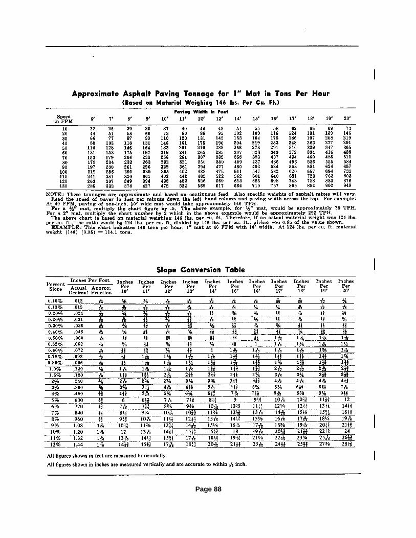
Page 88

TROUBLE-SHOOTING CHART
Page 89
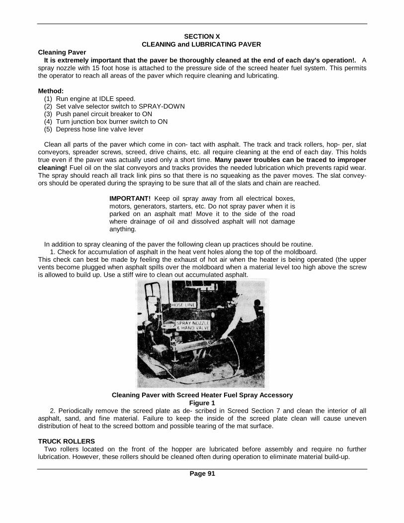
SECTION XCLEANING and LUBRICATING PAVER
Cleaning PaverIt is extremely important that the paver be thoroughly cleaned at the end of each day's operation!. A
spray nozzle with 15 foot hose is attached to the pressure side of the screed heater fuel system. This permitsthe operator to reach all areas of the paver which require cleaning and lubricating.
Method:(1) Run engine at IDLE speed.(2) Set valve selector switch to SPRAY-DOWN(3) Push panel circuit breaker to ON(4) Turn junction box burner switch to ON(5) Depress hose line valve lever
Clean all parts of the paver which come in con- tact with asphalt. The track and track rollers, hop- per, slatconveyors, spreader screws, screed, drive chains, etc. all require cleaning at the end of each day. This holdstrue even if the paver was actually used only a short time. Many paver troubles can be traced to impropercleaning! Fuel oil on the slat conveyors and tracks provides the needed lubrication which prevents rapid wear.The spray should reach all track link pins so that there is no squeaking as the paver moves. The slat convey-ors should be operated during the spraying to be sure that all of the slats and chain are reached.
IMPORTANT! Keep oil spray away from all electrical boxes,motors, generators, starters, etc. Do not spray paver when it isparked on an asphalt mat! Move it to the side of the roadwhere drainage of oil and dissolved asphalt will not damageanything.
In addition to spray cleaning of the paver the following clean up practices should be routine.1. Check for accumulation of asphalt in the heat vent holes along the top of the moldboard.
This check can best be made by feeling the exhaust of hot air when the heater is being operated (the uppervents become plugged when asphalt spills over the moldboard when a material level too high above the screwis allowed to build up. Use a stiff wire to clean out accumulated asphalt.
Cleaning Paver with Screed Heater Fuel Spray AccessoryFigure 1
2. Periodically remove the screed plate as de- scribed in Screed Section 7 and clean the interior of allasphalt, sand, and fine material. Failure to keep the inside of the screed plate clean will cause unevendistribution of heat to the screed bottom and possible tearing of the mat surface.
TRUCK ROLLERSTwo rollers located on the front of the hopper are lubricated before assembly and require no further
lubrication. However, these rollers should be cleaned often during operation to eliminate material build-up.
Page 91

LUBRICATION - GENERAL SUGGESTIONSPROPER LUBRICATION:
Proper Lubrication helps obtain top equipment performance and minimum down-time from worn outbearings. Make it a daily practice. Be sure to comply with all lubrication instructions on the following LubricationChart. Do not neglect any area or detail!
TOO MUCH GREASE:Too Much Grease pumped into bearing housings can overheat bearings and reduce their service life. Use
good judgment.
TOO MUCH LUBRICANT PRESSUREThe use of too much pressure when lubricating a sealed bearing can blow-out the soft seal ring. Once the
seal is blown, the bearing has no grease retention ability and no protection against the entry of dirt into the racearea. Rapid failure results!
When using a hand operated grease gun, stop pumping as soon as the easy stroking begins to change to ahard pumping requirement. When using a pressurized grease system, develop a "feel" for the correct pressureof gun against fitting for automatic pressure relief in case the bearing be- comes filled.
SELECTION OF LUBRICANTS:Texaco Lubricants are recommended on the lubrication chart following. Use only recommended lubricants.
GOOD HABITS:Cleanness when lubricating is vital! The grit which is always present around grease fittings and oil reserves
can destroy a good bearing surface rapidly if it is forced inside with the lubricap.When using a grease gun, wipe the nozzle clean before use.Wipe grease fittings absolutely clean before each application or keep them covered with the special plastic
Lubricaps which are on each paver fitting when it leaves the factory. Keep lubricaps clean while they are off thefittings. Leave an excess of grease on each fitting.
Don't wipe it off until the next greasing. It protects the fitting.Use grease gun with cartridge type supply unit for positive elimination of dirt and abrasive particles in the new
grease.
Plastic Lubricap for Bearing Grease FittingsFigure 2
COLOR CODED LUBRICAPSLubricaps can be installed on all fittings to keep the area around the grease fittings free from dirt and dust.
This Neoprene cap is easily removed and replaced. These inexpensive Lubricaps are available in quantitiesand can be ordered for placement on equipment in the field. Lubricaps are available in colors, so the customercan establish a coding system for different types and time intervals of lubrication. Grease guns and lubricantcontainers with matching color coding make correct lubricating routines easier.
Correct lubrication practices and continued use of the Lubricaps will insure the customer a longer bearing life,as well as eliminate many hours of unnecessary down time. It is important that the lubrication requirements bethoroughly under- stood and followed. SCHOOL YOUR LUBRICATION MAN.
Page 92

LUBRICATION DETAIL
(a) Bearing InspectionAnti-friction bearing assemblies should be checked immediately after stopping the paver, whenever possible,
as their failure is most easily detected by a high operating temperature. If a bearing is too hot to be touched, itis either running without any lubricant; with too much, or has failed.
(b) TransmissionThe main transmission for the "CEDARAPIDS" Bituminous Paver has a capacity of 17 quarts and should be
lubricated with Texaco Multigear or Universal Gear Lubricant EP 90. It is important that the operator check for aflow of oil through the sight gauge each day and check the level of the transmission when making generallubrication inspections. The transmission should be flushed with Rando AA oil every 1,000 hours or seasonally.(See lubrication chart.)
(c) Transfer Gear CasesThere are two transfer gear cases, one located on each side of the paver. Both have a capacity of 91/ quarts.
Use Texaco Multigear or Universal Gear Lubricant EP 90. The same instructions for flushing and checkingshould be followed as for the main transmission. (See lubrication chart.)
(d) Hydraulic SystemThe system has a capacity of 10 gallons. Use Texaco Rando HD-C Oil. When filling the reservoir tank it isimportant that the fluid is allowed time to flow and fill the system. Every 1,000 hours this system must bedrained, the strainer washed, and refilled with recommended lubricant. (See Section 5 for complete details).
(e) Slat Conveyor BearingsEach of the two slat conveyors have four bearings. Two are mounted at the front of the paver and two at theback. The lubrication of these bearings is important. They should be lubricated every 8 hours of operation withTexaco Marfak O lubricant.
(1) To lubricate front slat conveyor bearings, remove front hopper cover plate. (See lubrication chart.)(2) To lubricate rear slat conveyor bearings, see lubrication chart.
(f) Conveyor Drive ChainsThe four conveyor drive chains should be lubricated once each week to minimize wear. To reach the chains
connecting each conveyor drive shaft to the countershafts, remove the rear deck plate on each side of theengine. The two chains connecting the countershafts to the conveyor shafts are located directly beneath therear end of the engine and are readily accessible. Lightly coat all chain links with Texaco EP90 Universal GearLubricant. (Also used in the paver gear cases).
(g) Track Assembly(1) Crawler Track Link Pins - Spray fuel oil over crawler tracks when cleaning paver at the end of each
day's operation to lubricate link pins and keep them from squeaking.(2) Paver tracks are driven from the transfer cases with heavy duty chains and sprockets, that require
cleaning and lubricating at the end of the day's operation. Remove the two rear deck plates and spray fuel oilover the chain and sprocket using the wash-off hose from the heater fuel tank. This will normally keep theasphaltic material soft so that it falls off during the following day's operation.Failure to spray the chain can result in the asphaltic material building up in the chain and on the sprockets untilthe chain becomes so tight it will cause the chain to break.
CAUTION: When spraying chain andsprockets, use care not to spray theelectric clutch on transfer case.
(3) Lower roller and track roller and pivot shaft assemblies are equipped with grease fittings to lubricate thepivot pins and each roller with Texaco Marfak O lubricant every 8 hours of operation. (See lubrication chart).
(4) Track rear sprocket or front idler - Once each year remove the fill plugs and install grease fitting. AddTexaco Marfak O lubricant until new lubricant appears at opposite pipe plug hole. Re- move fitting and replaceboth pipe lugs. (See illustrations in Maintenance Section II)
(h) Spreader Screw BearingsAll bearings for the spreader screws have grease fittings which are easily accessible and should be' lubricated
every 8 hours of operation. It is important these fittings be cleaned before lubricant is applied. Use TexacoMarfak O lubricant. (See lubrication chart).
(i) Travel and Feed Clutches - All travel and feed clutch bearing assemblies must be disassembled andrepacked with Texaco Marfak O lubricant every season.
Page 93
(j) Screed Adjusting Mechanism and Pull ArmsBall joint housings on screed adjusting mechanisms and pull arms are equipped with grease fittings to
lubricate the ball joints with Texaco Marfak O lubricant every 8 hours of operation. (See lubrication chart).(k) Pulleys For Screed Lift CablesThere are two pulleys for each screed lift cable and each has a grease fitting. The fitting of the enclosed
pulley is not in plain sight. All four fittings should be greased once each month(1) Power UnitThe diesel engine that powers the paver must be properly lubricated and maintained to insure the dependable
and smooth performance needed in a paving operation.An individual instruction manual is provided, carefully outlining intervals of time to lubricate, clean air filter,
and change oil along with other points of preventative maintenance. More frequent replacement or cleaning ofair filter will be required in dusty conditions.
Page 94
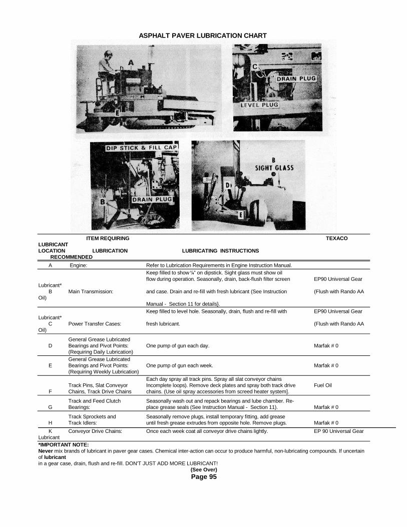
ASPHALT PAVER LUBRICATION CHART
ITEM REQUIRING TEXACOLUBRICANTLOCATION LUBRICATION LUBRICATING INSTRUCTIONS
RECOMMENDED
A Engine: Refer to Lubrication Requirements in Engine Instruction Manual.Keep filled to show ” on dipstick. Sight glass must show oilflow during operation. Seasonally, drain, back-flush filter screen EP90 Universal Gear
Lubricant*B Main Transmission: and case. Drain and re-fill with fresh lubricant (See Instruction (Flush with Rando AA
Oil)Manual - Section 11 for details}.Keep filled to level hole. Seasonally, drain, flush and re-fill with EP90 Universal Gear
Lubricant*C Power Transfer Cases: fresh lubricant. (Flush with Rando AA
Oil)
General Grease LubricatedD Bearings and Pivot Points: One pump of gun each day. Marfak # 0
(Requiring Daily Lubrication)General Grease Lubricated
E Bearings and Pivot Points: One pump of gun each week. Marfak # 0(Requiring Weekly Lubrication)
Each day spray all track pins. Spray all slat conveyor chainsTrack Pins, Slat Conveyor Incomplete loops). Remove deck plates and spray both track drive Fuel Oil
F Chains, Track Drive Chains chains. (Use oil spray accessories from screed heater system].
Track and Feed Clutch Seasonally wash out and repack bearings and lube chamber. Re-G Bearings: place grease seals (See Instruction Manual - Section 11). Marfak # 0
Track Sprockets and Seasonally remove plugs, install temporary fitting, add greaseH Track Idlers: until fresh grease extrudes from opposite hole. Remove plugs. Marfak # 0
K Conveyor Drive Chains: Once each week coat all conveyor drive chains lightly. EP 90 Universal GearLubricant*IMPORTANT NOTE:Never mix brands of lubricant in paver gear cases. Chemical inter-action can occur to produce harmful, non-lubricating compounds. If uncertainof lubricantin a gear case, drain, flush and re-fill. DON'T JUST ADD MORE LUBRICANT!
(See Over)Page 95
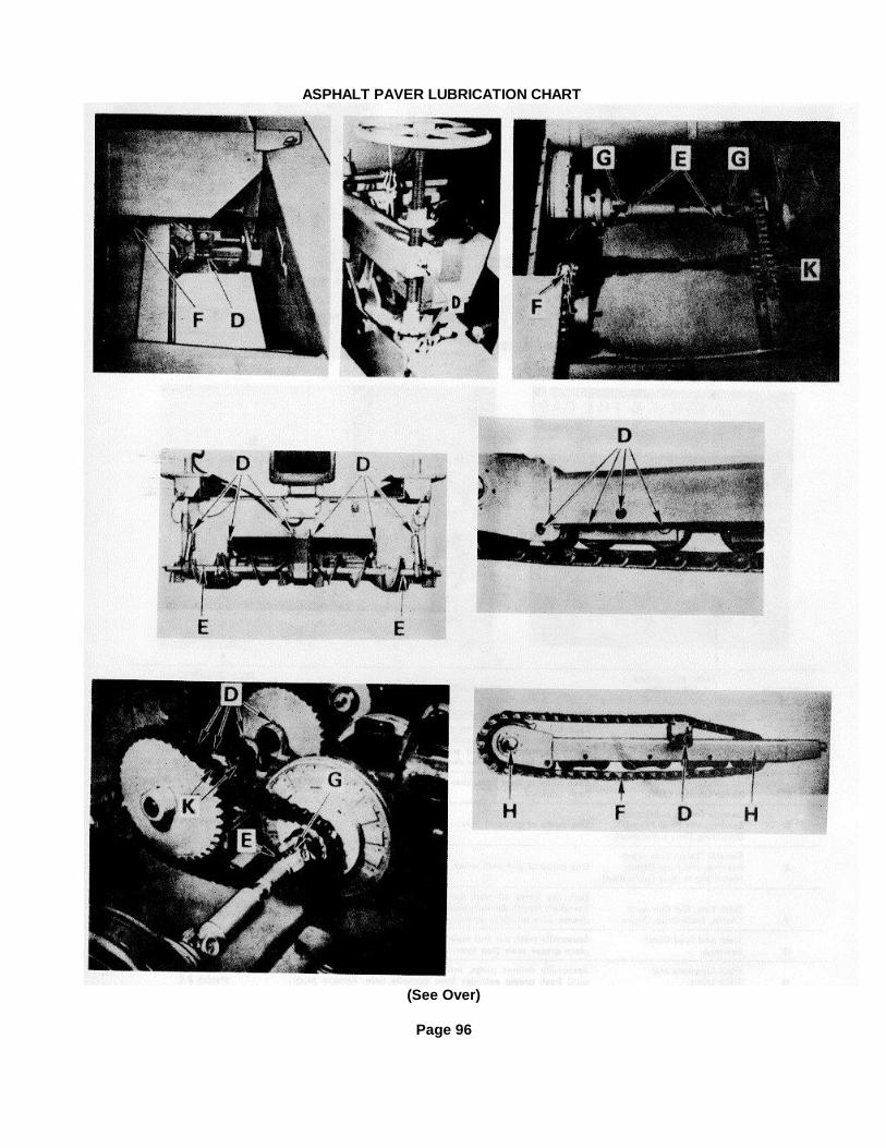
ASPHALT PAVER LUBRICATION CHART
(See Over)
Page 96

SECTION XIMechanical Maintenance
TABLE OF CONTENTS
Subject Page
Crawler Tracks .......................................................................................................... 99-102Adjusting tension ................................................................................................. 99Replacing track assembly .................................................................................... 100Replacing oscillating roller ................................................................................... 100Drive chain take-up .............................................................................................. 101Replacing track sprockets ........................................ ........................................... 101Lubricating track sprocket and track idler bearings .................. ............................ 101Replacement of huck-bolted sprockets .............................. .................................. 102
Track Drive Transfer Cases ...................................................................................... 103-108Checking for wear ............................................... ................................................ 103internal inspection and adjustment ................................. ..................................... 104Case repair ..................................................... .................................................... 107
Slat Conveyors .................................................... ..................................................... 109-110Slat turn-over ................................................... ................................................... 109Slat chain take-up ............................................... ................................................ 109Conveyor drive chain take-up .............................................................................. 109Replacing liners under slat conveyors .............................. ................................... 110
Screw Conveyors ......................................................................................................110 &111
Restoring screws to original diameter .............................. .................................... 110Refacing screws with Ni-hard liners ................................ ..................................... 110
Electric Clutches - travel and feed ...........................................................................112 &113
Inspection of clutches .......................................................................................... 112Adjustment of clutches ........................................... ............................................. 112Replacing worn-out clutch parts ........................................................................... 113
Screed Assembly ............................................... ....................................................... 114-116Removing quick-change bottom ................................... ....................................... 114Installing new bottom ............................................ .............................................. 114Checking bolts .................................................. .................................................. 114Handwheel screw maintenance ...........................................................................115 &
116
Vibrator Control Knob Installation & Tight ening .................................................... 117
Page 97

TABLE OF CONTENTSContinued
Electrically Released Track Brakes ......................................................................... 117-119General information ............................................................................................ 117Armature clearance ............................................................................................. 118Wear pattern ....................................................................................................... 118Replacing worn-out parts ..................................................................................... 118Brake electrical module........................................................................................ 119
Main Clutch (manually Operated) ............................................................................120 &121
Clutch adjustment ............................................................................................... 121
Engine Power Take-off Assembly ............................................................................ 121
24 Speed Transmission (Manually Shifted) ............................................................ 122-128Component part description ................................................................................ 122-127Assembly of parts on bevel pinion shaft .............................................................. 123Replace of transmission oil pump......................................................................... 127Transmission oil line filter ....................................................................................127 &
128
125 Volt A.C. Generator ............................................................................................128 &129
Loss of voltage .................................................................................................... 128Maintenance .................................................... ................................................... 128V-belt tension .................................................... .................................................. 129
12 Volt D.C. Generator .............................................................................................. 129
Seasonal Paver Overhaul Recommendations.......................................................... 130
Page 98

CRAWLER TRACKSThe most expensive mistake the owner of any track type piece of equipment can make is to assume that
such an uncomplicated mechanism as a crawler track needs no care. An effective service life is built into thetrack, but without proper care its life will be shortened.
The track, rollers, sprockets and take up idlers should be inspected at least once a week. Lubrication shouldbe according to recommendations. Everytime the paver is cleaned, the track should be sprayed with fuel oil.There is enough lubricant in the fuel oil to keep the track pins from rusting and binding.
Track tension is most important. The tension de- termination method shown in Figure 2 is a guide. Propertrack tension depends on the type of laying operation. When the base is sandy there tends to be a buildupon the track bushings. This material will pack and the track tension will increase. The drive sprocket will jump inthe track and cause excessive strain on the rear track sprocket bearings and front idler bearings.If the tracks are too tight, there is unnecessary strain on the drive assembly and the engine will lug excessively,and fuel consumption will be high.
A very loose track has a tendency to come off when the machine pivots or backs up an incline. Even if itdoes not come off a loose track still may cause wear on the rollers, sprocket teeth and track. Loose track willtend to whip at travel speeds, which will cause severe impact loads on all running gear parts and allowadditional movement of the contacting surfaces, which consequently increases wear to all parts.
IMPORTANT! A new paver or one having a new set of tracks will require daily tightening of the tracks until alllink pins have "worn in" and stretching of the track no longer occurs. When this initial stretching stops it will onlybe necessary to check and tighten the tracks occasionally.
Method of Adjusting Track Tension:1. Drive the paver to a point where the front end overhangs the track support surface enough to allow the
movement of a long handled wrench engaging the track adjusting Nut "B" on each side of the paver (SeeFigure 3).
2. Loosen the locknut and turn Adjusting Nut "B" in the normal way to tighten or loosen.
Bottom View of Tractor Assembly Measuring Track. TensionFigure 1 Figure 2
3. Take a measurement of the sag in each track (See Figure 2) and adjust the tension accordingly to arriveat the 67/g" dimension shown. Be sure to measure at the lowest point of track sag.
4. Tighten the locknuts after making an adjustment.Tension Pre-load:
A minimum tension on the track is set at the factory by adjustment of the "pre-load". The spring is partlycompressed by the Cap which is drawn to within 2" or 2¼¥4" of the Base Plate (See Figure 3) by adjustment ofthe stud Hex Nuts"C". This Portion of the tension assembly requires no further adjustment! If a spring or other parts arereplaced, adjust the Pre-load to this specified dimension.
Page 99

Track Tension Adjustment (Factory assembly view) Track Link and Pin DetailFigure 3 Figure 4
CAUTION! Always take the proper precautions when making such an adjustment where parts are subjectedto strong spring tension.Replacing Crawler Track Assembly(1) Removing Crawler Assembly: (Figure 4)
a. Elevate paver to allow adequate working area under the hopper.b. Release tension on track assembly.c. Drive the roll pins out of each end of one of the track pins.d. Drive track pin out of crawler link.e. Attach a cable to the "broken" track and pull track off track frame.
(2) Replacing Crawler Assembly:One complete track is shipped in two sections for ease of handling. One section of the track will have one (1)
more link than the other section. Couple these two sections together with track pin for one complete trackassembly.
a. Place blocking of sufficient height on top of track frame to support tracks level with upper rollerassembly.
b. Attach cable to one end of the track assembly and pull tracks over top of track frame until looseends of track are under track frame toward the hopper end.
c. Couple the two ends of tracks together with track pin.d. Drive roll pin into each end of track pin.e. Adjust track to the recommended tension.f. Release and remove jacks that elevated paver.
Oscillating Track Roller (Partially dismantled)Figure 5
Replacing Oscillating Roller Assembly(Figure 5)
Three sets of oscillating track roller assemblies are part of each track assembly. When bushings and rollersrequire replacement, these assemblies can quickly be removed from the track frame by the followingprocedures:
IMPORTANT: Operating paver with worn track roller bushings will cause wavy surfaces on the laid mat,and unsatisfactory transverse joints, erratic depth control and marks on mat when paver stops. (1) Elevatemachine until it is possible to loosen track take-up assembly allowing track to hang free.
(2) Remove the complete oscillating roller assembly by removing the four nuts "A" which hold it to the trackframe.
(3) To further disassemble the rollers from the oscillating assembly, remove bolt and lock, Items "B" and "C."Then, push shaft through the roller.
Page 100
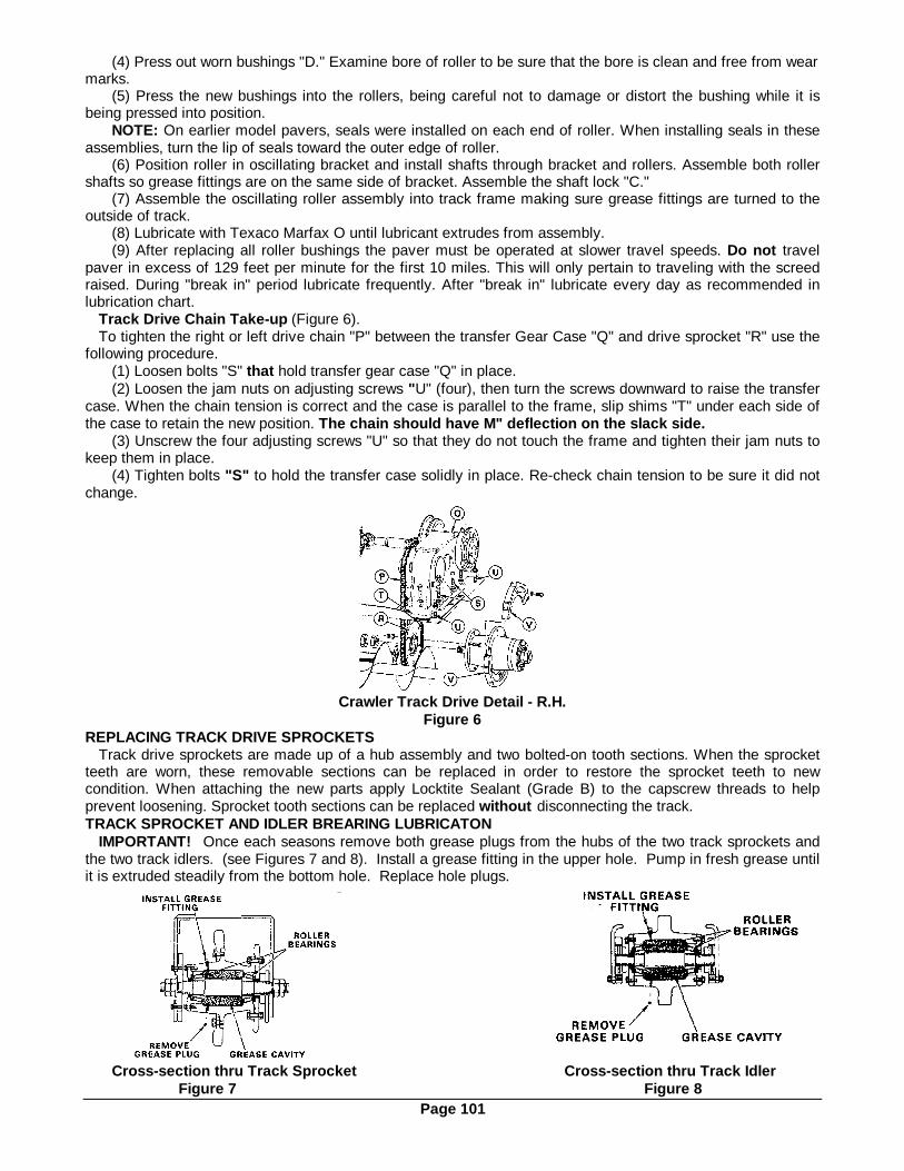
(4) Press out worn bushings "D." Examine bore of roller to be sure that the bore is clean and free from wearmarks.
(5) Press the new bushings into the rollers, being careful not to damage or distort the bushing while it isbeing pressed into position.
NOTE: On earlier model pavers, seals were installed on each end of roller. When installing seals in theseassemblies, turn the lip of seals toward the outer edge of roller.
(6) Position roller in oscillating bracket and install shafts through bracket and rollers. Assemble both rollershafts so grease fittings are on the same side of bracket. Assemble the shaft lock "C."
(7) Assemble the oscillating roller assembly into track frame making sure grease fittings are turned to theoutside of track.
(8) Lubricate with Texaco Marfax O until lubricant extrudes from assembly.(9) After replacing all roller bushings the paver must be operated at slower travel speeds. Do not travel
paver in excess of 129 feet per minute for the first 10 miles. This will only pertain to traveling with the screedraised. During "break in" period lubricate frequently. After "break in" lubricate every day as recommended inlubrication chart.
Track Drive Chain Take-up (Figure 6).To tighten the right or left drive chain "P" between the transfer Gear Case "Q" and drive sprocket "R" use the
following procedure.(1) Loosen bolts "S" that hold transfer gear case "Q" in place.(2) Loosen the jam nuts on adjusting screws "U" (four), then turn the screws downward to raise the transfer
case. When the chain tension is correct and the case is parallel to the frame, slip shims "T" under each side ofthe case to retain the new position. The chain should have M" deflection on the slack side.
(3) Unscrew the four adjusting screws "U" so that they do not touch the frame and tighten their jam nuts tokeep them in place.
(4) Tighten bolts "S" to hold the transfer case solidly in place. Re-check chain tension to be sure it did notchange.
Crawler Track Drive Detail - R.H.Figure 6
REPLACING TRACK DRIVE SPROCKETSTrack drive sprockets are made up of a hub assembly and two bolted-on tooth sections. When the sprocket
teeth are worn, these removable sections can be replaced in order to restore the sprocket teeth to newcondition. When attaching the new parts apply Locktite Sealant (Grade B) to the capscrew threads to helpprevent loosening. Sprocket tooth sections can be replaced without disconnecting the track.TRACK SPROCKET AND IDLER BREARING LUBRICATON
IMPORTANT! Once each seasons remove both grease plugs from the hubs of the two track sprockets andthe two track idlers. (see Figures 7 and 8). Install a grease fitting in the upper hole. Pump in fresh grease untilit is extruded steadily from the bottom hole. Replace hole plugs.
Cross-section thru Track Sprocket Cross-section thru Track IdlerFigure 7 Figure 8
Page 101
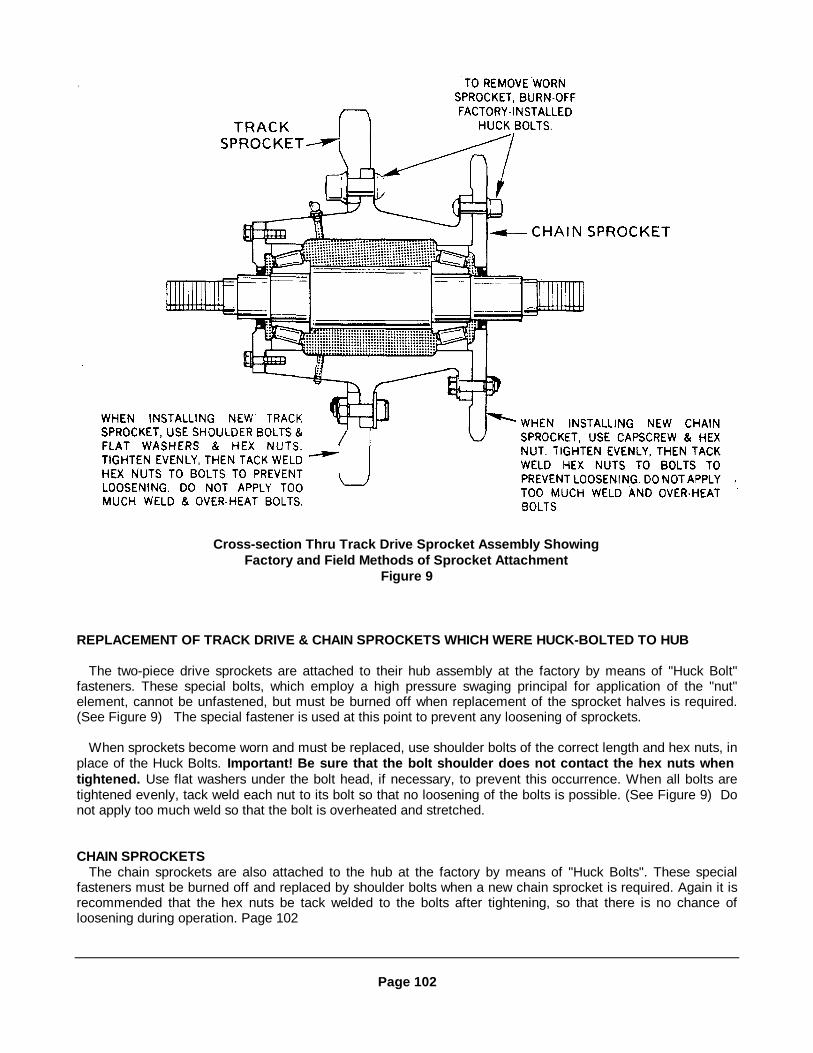
Cross-section Thru Track Drive Sprocket Assembly ShowingFactory and Field Methods of Sprocket Attachment
Figure 9
REPLACEMENT OF TRACK DRIVE & CHAIN SPROCKETS WHICH WERE HUCK-BOLTED TO HUB
The two-piece drive sprockets are attached to their hub assembly at the factory by means of "Huck Bolt"fasteners. These special bolts, which employ a high pressure swaging principal for application of the "nut"element, cannot be unfastened, but must be burned off when replacement of the sprocket halves is required.(See Figure 9) The special fastener is used at this point to prevent any loosening of sprockets.
When sprockets become worn and must be replaced, use shoulder bolts of the correct length and hex nuts, inplace of the Huck Bolts. Important! Be sure that the bolt shoulder does not contact the hex nuts whentightened. Use flat washers under the bolt head, if necessary, to prevent this occurrence. When all bolts aretightened evenly, tack weld each nut to its bolt so that no loosening of the bolts is possible. (See Figure 9) Donot apply too much weld so that the bolt is overheated and stretched.
CHAIN SPROCKETSThe chain sprockets are also attached to the hub at the factory by means of "Huck Bolts". These special
fasteners must be burned off and replaced by shoulder bolts when a new chain sprocket is required. Again it isrecommended that the hex nuts be tack welded to the bolts after tightening, so that there is no chance ofloosening during operation. Page 102
Page 102

Checking Shaft Bearings For Looseness Figure 10
CHECKING & ADJUSTING TRACK DRIVE TRANSFER CASES
The two transfer cases for the track drive system can best be protected against shock loading andsubsequent bearing wear by keeping the tracks and the drive chains properly tightened and well lubricated.When a paver is operated with loose tracks and drive chains, shock loading occurs each time the travelclutches and brakes are engaged. The tapered roller bearings and gears on the output shaft, and the ballbearings and pinion on the stub shaft, are subjected to extreme stress each time the paver starts and stops.
Extreme drive loading also occurs when tracks and drive chains are allowed to accumulate a coating ofhardened asphalt. It is important that they be spray cleaned and lubricated thoroughly with fuel oil after eachdays operation so that the asphalt remains soft and drops off during subsequent operation. Whenexcessive loading is allowed to occur due to inadequate spray cleaning, the drive chains are stretched anddevelop the looseness that increases shock loading.
It is recommended that the tension of the drive chains be checked after each week of operation. Whencorrectly tightened a drive chain can just barely be deflected by hand. It should not be drawn up "drum tight".
It is also recommended that anytime a loose chain is to be tightened, the output shaft of that transfer casebe carefully checked for looseness.
This can be done as follows:(1) With paver engine stopped and track brakes Off, turn the clutch rotor on the transfer case so that
there is an equal amount of slack in the drive chain on both sides of the sprocket.(2) Using a pry bar and some blocking as shown in Figure 10, put some upward pressure on the output
shaft and see if any vertical movement of the shaft is noticeable. Exert some end wise pressure on the shaft inboth directions and see if any horizontal movement of the shaft is noticeable. The output shaft bearings arepre-loaded at assembly and there should be no movement possible in any direction. If there is noticeablemovement it is strongly recommended that the transfer case be repaired or adjusted so that a part failure doesnot occur during operation. The cost of inspection, adjustment, replacement, or field repair during an out-of-service maintenance period is far less than the cost of a break-down during paving.
Page 103

L.H. Transfer Case (Current Model) - Exploded View Figure 11
TRANSFER CASE INSPECTION & ADJUSTMENTA.- Remove the transfer case from the paver and move it to a shop area where the unit can be opened,cleaned and inspected internally without risk of contamination from wind borne dust, etc.
B.- Before opening a transfer case clean the outside surfaces of all loose dirt.
C.- Remove the case cover. Drain the oil and flush the interior with solvent to remove all oil and residue.
D.- Inspect the gears for their wear patterns. (See Figure 13) Pay particular attention to the wear patterns ofgears (29) and (37), Figures 11 and 12, as the drive loading is greatest on these gears. If any gears in the caseshow signs of improper wear or if there is a looseness of any shaft or bearing, the case should be dismantledand checked for the following requirements:
(1) All bearings must be tight in the case or retainer. If they are loose due to an out-of-round bore, a newbearing will not correct the looseness. Pay particular attention to output shaft area. (Bearings 34 and 39).
(2) All bearings must be in good condition. Worn bearings cannot maintain the high degree of shaftalignment required.
(3) All shafts must be rigidly fixed in a parallel attitude.
(4) Input shaft should not have more than .003” end float. (See Step E)
(5) Tapered roller bearings on output shaft must be accurately pre-loaded. (See Step H)
(6) Oil seals must be in good condition so that a rapid loss of oil does not occur.
E.- If necessary, make a micrometer check at the two critical points on each bearing retainer (3) and (15) forthe input shaft (12). See Figure 16 for correct dimensions. In the event they are worn out- of-tolerance replacethe retainers.
Adjust the clearance of the tapered bearings (6) and (7) on input shaft (12). This is done by adjustingshim kit (4) so that the shaft has .001" to .003" end float. (Important! The installation of new bearings willhelp assure trouble-free performance.)
F. - Carefully check the two stub shafts for vertical looseness. If there is looseness in shafts(22) or (28)-replace the ball bearings (20) and (26). (There is no ball bearing adjustment.) However, before installing newbearings at these points check. The bores of the housing for size, roundness, and axial alignment. (SeeFigures 17 and 18 for correct
Page 104

L.H. Transfer Case (Current Model) - Cross Section View Figure 12
Item Part Description3 Cover, Mounting4 Shim Kit5 Seal, Oil6 Roller Bearing7 Roller Bearing12 Shaft, Input13 Pinion, Input14 Snap Ring15 Cover, Mounting19 Cover, Bearing20 Ball Bearing21 Gear, Drive22 Shaft, Stub23 Gear, Driven24 Cover, Bearing25 Cover, Bearing26 Ball Bearing27 Gear, Intermediate28 Shaft, Stub29 Gear, Drive32 Retainer, Bearing33 Shim Kit34 Roller Bearing35 Gasket36 Spacer, Output Shaft37 Gear, Output38 Shaft, Output39 Roller Bearing40 Gasket41 Seal, Oil42 Carrier, Bearing
Page 105

Examples Of Gear Tooth Wear Patterns Figure 13
Start Rolling Torque Test Rotation Figure 14
Reading Rolling Torque Test Scale Figure 15dimensions.) This should be done with machinists gauges or micrometers. When bores are oversize or out-of-round, ashock loading occurs during operation and new bearings are quickly ruined. Refer to paragraph J headed "Case Repair"which follows.
Important! Leave the stub shaft (28) out of the case until after the rolling torque check is made on the output shaftas described in Step I.
G.- Check the bore of the housing for correct diameter, roundness, and axial alignment at the points where output shaftbearings (34) and (39) are installed. It is vitally important that these bores be correct as shown in Figures 17 and 18. Ifthey do not conform to specifications, refer to Step J covering case repair.
H.- Adjust the clearance of the tapered bearings (34) and (39) to produce a .014" pre-load. This is done by adjustingshim pack (33) so that all end float is just barely eliminated, then removing .014" from shim pack (33) and againtightening the bearings retainer screws.
NOTE: When normal deflection of the transfer case walls occurs, the pre-load will actually be considerablyless than .014". The rolling torque check described in the following paragraph should be made to verifythat an accurate pre-load has been set.
I.- Make a rolling torque check of the output shaft pre-load in the following manner:
(1) Remove pinion shaft assembly (28) from the case so that output shaft (38) will be free to rotate.
Page 106

(2) Install the chain sprocket on the output shaft.
(3) Obtain a 10 ft. length of strong cord (50 lb. test) and a reliable hand-held spring scale such as the onesupplied with each paver Duo-matic system for ade line tensioning. (0 to 100 lbs. capacity).
(4) Tie one end of the cord to a sprocket and tooth, then wind several wraps around the sprocket hub and attachthe spring scale hook.
(5) Pull on the scale to tighten the cord and use your free hand to start rotation of the sprocket. (See Figure 14)Observe the amount of pull required to keep the sprocket turning.(See Figure 15)If the pre-load is correct, a pull of 16to 24 lbs. will be required. (This equals 40 to 60 inch pounds of torque; 16 to 24 x 2.5" radius of sprocket hub). If morethan 24 lbs. of pull is required, add some shim thickness to loosen the pre-load. If less than 16 lbs. is required, removesome shim thickness.
CASE REPAIR
J.- It is vitally important that all bearing bores in the transfer case be in "new part" condition in order for bearings andshafts to be accurately aligned and rigidly held. If a bore is worn over-size or out-of- round by an old bearing, areplacement bearing will fail rapidly. This is due to the shock loading which results from a hammering action and frommisalignment of the shaft.
If parts have failed in a case, or severe mismatch of gear teeth has produced a poor "wear pattern" the case boresshould be checked by a machinist, using micrometers, dial indicators, etc. The factory dimensions given in Figures 16thru 18 will provide the necessary checking details. If serious discrepancies are found, the case should be replaced, orfield re-built to new condition.
Bearing retainers and carriers as shown in Figure 16 must also have accurate bore and diameter. Re- place anyones that do not conform to specified tolerances.
Removable Bearing Supports Figure 16
Page 107

Transfer Case - Side View Figure 17
Transfer Case - Top View Figure 18
Note: Case bores must be axially aligned with mating bores.
Page 108

Slat Conveyor Chain Tightener (Four Used) Figure 19SLAT CONVEYORSInverting Slat Bars
The right and left slat conveyors consist of a series of bars, linked together by two continuous chains attached tothe end of the bars. Either the right or left slat conveyor can be turned over to allow use of the other side as follows:
(1) Loosen chain (refer to following paragraph).(2) Remove pin from chain link and break chain.(3) Turn slat conveyor over and replace.(4) Couple chain.(5) Tighten chain.
Slat Conveyor Take-upTo adjust chain (Refer to Figure 19):(1) Remove hopper end cover plate "B" from intake end of hopper "A".(2) Loosen lock-nut "C" and tighten take-up.(3) To loosen chain, loosen take-up nut "D".(4) Tighten locknut "C" after proper adjustment.IMPORTANT! Care should be taken that the two chains of each conveyor are tightened equally. The chain will be
properly tightened when 1" sag is present between return track and front sprockets.CAUTION: DO NOT OVER-TIGHTEN. THIS WILL CAUSE EXCESS WEAR ON CHAIN. Also be sure that chain
cover guards are in good repairs for maximum protection to the chain from the feed materials.(5) When chain is properly tightened, replace hopper end cover plate before operating.
Slat Conveyor & Spreader Screw Drive Chain Take-up (Refer to Figure 20)The right slat conveyor and spreader screw and the left slat conveyor and spreader screw are driven by individual
chain drives.To tighten chain (be sure engine is not running):(1) Remove bolts "A" that holds cover plate "B" in place.(2) Remove cover plate "B".(3) Loosen bolts "C" that hold Idler shaft take-up plates "D" in place.NOTE: Idler shaft take-up plates are slotted for chain adjustment. To tighten chains, slide idler shaft take-up
plates forward and tighten bolts. When slots are used up in plates, slide plates back, tighten bolts "C" and make thefollowing adjustments:
(4) Loosen nuts "E" that hold take-up plates "F” in place.(5) Make chain adjustment with bolt "H".(6) If the limit of adjustment is reached before the chains are tight, back off bolts "H" to relieve tension of carriage
bolts "E".(7) Shift carriage bolts E to the adjacent hole in Support "G" to obtain maximum adjustment, then readjust bolts
"H".(8) With sprockets "J" and "K" in line, tighten nuts "E".(9) Check tightness at opening "L". When both chains are properly adjusted, there should be a deflection of
approximately 1/2" on each chain. It is important to maintain this tightness at all times!(10) Replace cover plate "B".(11) If chain "M" is too loose (dragging on deck) break chain and remove link or /2 link until properly adjusted. This
chain can run looser than those in Step 9.
Conveyor Drive Chain Tighteners Figure 20Page 109
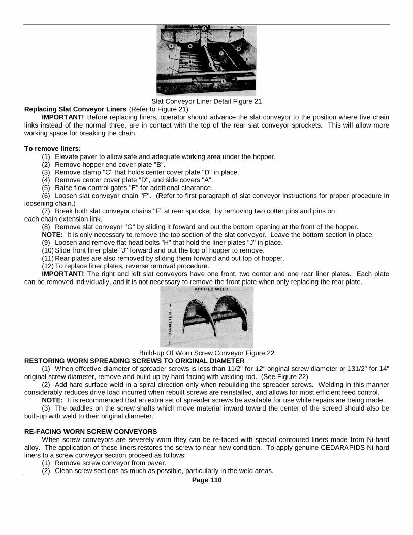
Slat Conveyor Liner Detail Figure 21Replacing Slat Conveyor Liners (Refer to Figure 21)
IMPORTANT! Before replacing liners, operator should advance the slat conveyor to the position where five chainlinks instead of the normal three, are in contact with the top of the rear slat conveyor sprockets. This will allow moreworking space for breaking the chain.
To remove liners:(1) Elevate paver to allow safe and adequate working area under the hopper.(2) Remove hopper end cover plate "B".(3) Remove clamp "C" that holds center cover plate "D" in place.(4) Remove center cover plate "D", and side covers "A".(5) Raise flow control gates "E" for additional clearance.(6) Loosen slat conveyor chain "F". (Refer to first paragraph of slat conveyor instructions for proper procedure in
loosening chain.)(7) Break both slat conveyor chains "F” at rear sprocket, by removing two cotter pins and pins on
each chain extension link.(8) Remove slat conveyor "G" by sliding it forward and out the bottom opening at the front of the hopper.NOTE: It is only necessary to remove the top section of the slat conveyor. Leave the bottom section in place.(9) Loosen and remove flat head bolts "H" that hold the liner plates "J" in place.(10) Slide front liner plate "J" forward and out the top of hopper to remove.(11) Rear plates are also removed by sliding them forward and out top of hopper.(12) To replace liner plates, reverse removal procedure.IMPORTANT! The right and left slat conveyors have one front, two center and one rear liner plates. Each plate
can be removed individually, and it is not necessary to remove the front plate when only replacing the rear plate.
Build-up Of Worn Screw Conveyor Figure 22RESTORING WORN SPREADING SCREWS TO ORIGINAL DIAMETER
(1) When effective diameter of spreader screws is less than 11/2" for 12" original screw diameter or 131/2" for 14"original screw diameter, remove and build up by hard facing with welding rod. (See Figure 22)
(2) Add hard surface weld in a spiral direction only when rebuilding the spreader screws. Welding in this mannerconsiderably reduces drive load incurred when rebuilt screws are reinstalled, and allows for most efficient feed control.
NOTE: It is recommended that an extra set of spreader screws be available for use while repairs are being made.(3) The paddles on the screw shafts which move material inward toward the center of the screed should also be
built-up with weld to their original diameter.
RE-FACING WORN SCREW CONVEYORSWhen screw conveyors are severely worn they can be re-faced with special contoured liners made from Ni-hard
alloy. The application of these liners restores the screw to near new condition. To apply genuine CEDARAPIDS Ni-hardliners to a screw conveyor section proceed as follows:
(1) Remove screw conveyor from paver.(2) Clean screw sections as much as possible, particularly in the weld areas.
Page 110

Formed Ni-hard Liner For Screw Conveyors Figure 23(3) Using several C-clamps attach the pieces of liner to the screw face starting at the drive shaft end as shown in
Figure 24. By starting at this end, the main wear surface of the section will be covered and any small area not coveredwill be at the discharge end. Adjust liner pieces to extend about 1/8" above the edges of the screw flight as shown inFigure 27. Be sure that the first piece applied is accurately aligned so that the remaining liners will fit properly along theflight.
(4) Using only a low hydrogen weld rod make a continuous weld along the inside edge ("A" Figures 24 and 27).Make welds at each of the two Pockets ("B" Figures 25 and 27). On the first and last liners of each flight make a weld atthe exposed edge ("C" Figure 26) for extra strength.
NOTE: The small cracks which develop in the liners from the welding process are normal and should not beconsidered defects.
Making Hub Weld Figure 24
Filling Weld Pockets Figure 25
Welding Liner Edge Figure 26
Cross-section Thru Screw Flight & Liner Figure 27
Page 111

Electric Clutches - RH SideFigure 28
ELECTRIC CLUTCHES - TRAVEL & FEED
InspectionThe life span of the clutches will be increased by making a thorough periodic inspection.The operator should be familiar with the operation of these clutches. He should assume the responsibility of
inspecting and maintaining each clutch as follows:(1) Check to see that clutches are free from oil and grease.(2) Clean clutches with oil-free solvents.(3) Keep clutches covered by walkways.IMPORTANT! Keep walkways in place except when servicing.(4) Check electrical wiring for all clutches to see if there are any loose connections or broken wires.(5) Maintain a minimum opening of .046" (3/64") between the Armature "C" and Rotor "B". (See Figure 29) This
dimension should be checked simultaneously at 3 points, 120° apart. All present paver clutches have a Scribe Line onthe OD of the field "A" for assembly purposes, align the inward edge of the outer pole of the Rotor "B" with this ScribeLine visually to a tolerance of plus 1/32" minus .000". This setting will provide proper clearance internally between theRotor and the field.
(6) Pavers in the field without Scribe Line maintain the measurement of 3/4" .008" between the outer edge of theField Mounting Flange "A" and edge of Rotor "B".
CAUTION: If dimension is less or Field "A" is rubbing against Rotor "B", DO NOT MOVE MACHINE. Make thefollowing adjustments to eliminate clutch damage.
Feed Clutch Adjustment (Refer to Figure 29)NOTE: Travel clutch is identical except for hub detail.(1) To adjust clutch for .046" (3/64") opening, loosen set screws "P" on Hub "F” and move Hub until proper
measurement of .046" is reached between Rotor "B" and Armature "C". Check this measurement at three points aroundthe circumference of the clutch. Tighten set screws "P" and be sure Armature "C" slides free on pin "Q".
(2) To adjust clutch for alignment to the Scribe Mark within + 1 / 32" minus .000”, remove bolts "G" that hold DriveAssembly "H" in place. Detach Drive Assembly "H". Free Lock Washer "J" from Nut "K" and remove Nut "K". RemoveWasher "J" and "L". Remove Chain from Sprocket "M". Use Bearing Puller to remove Hub and Armature Assemblyfrom Shaft. Remove Two Set Screws "N” that hold Taper-lok Bushing "E" and Rotor Hub"D" in place.
CAUTION: DO NOT DETACH Hub "D", from Rotor "B" for this particular clutch adjustment. LEAVE HUB "D"INPLACE.
(3) By adjusting Taper-lok Bushing "E" the alignment of the Rotor "D" can be obtained. Before assembling RotorHub "D" to Tapered Bushing "E", rinse mating parts and shaft with solvent to remove any oil film on parts to beassembled.
(4) Assemble Rotor and Taper-lok Bushing on shaft and tighten set screws "N" to 800-inch lbs. wrench-torque onscrews. After tightening, rap bushing with hammer to seat it into hub. Tighten set screws again. Repeat alternatehammering and screw tightening until 800-inch lbs. wrench-torque can no longer move the screws.
Page 112
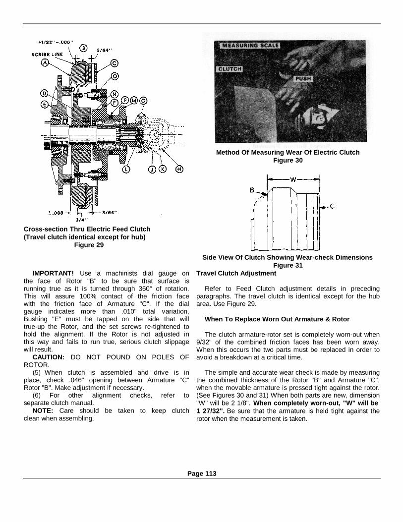
Cross-section Thru Electric Feed Clutch(Travel clutch identical except for hub)
Figure 29
Method Of Measuring Wear Of Electric ClutchFigure 30
Side View Of Clutch Showing Wear-check DimensionsFigure 31
IMPORTANT! Use a machinists dial gauge onthe face of Rotor "B" to be sure that surface isrunning true as it is turned through 360° of rotation.This will assure 100% contact of the friction facewith the friction face of Armature "C". If the dialgauge indicates more than .010" total variation,Bushing "E" must be tapped on the side that willtrue-up the Rotor, and the set screws re-tightened tohold the alignment. If the Rotor is not adjusted inthis way and fails to run true, serious clutch slippagewill result.
CAUTION: DO NOT POUND ON POLES OFROTOR.
(5) When clutch is assembled and drive is inplace, check .046" opening between Armature "C"Rotor "B". Make adjustment if necessary.
(6) For other alignment checks, refer toseparate clutch manual.
NOTE: Care should be taken to keep clutchclean when assembling.
Travel Clutch Adjustment
Refer to Feed Clutch adjustment details in precedingparagraphs. The travel clutch is identical except for the hubarea. Use Figure 29.
When To Replace Worn Out Armature & Rotor
The clutch armature-rotor set is completely worn-out when9/32" of the combined friction faces has been worn away.When this occurs the two parts must be replaced in order toavoid a breakdown at a critical time.
The simple and accurate wear check is made by measuringthe combined thickness of the Rotor "B" and Armature "C",when the movable armature is pressed tight against the rotor.(See Figures 30 and 31) When both parts are new, dimension"W" will be 2 1/8". When completely worn-out, "W" will be1 27/32". Be sure that the armature is held tight against therotor when the measurement is taken.
Page 113
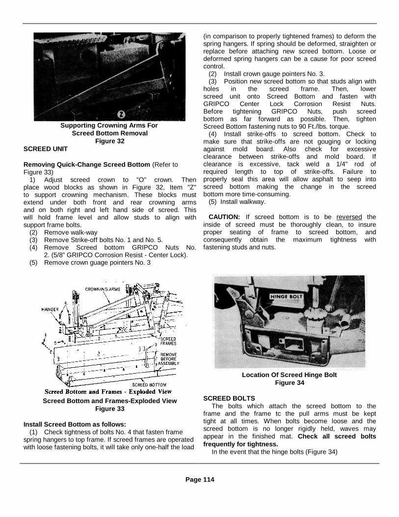
Supporting Crowning Arms ForScreed Bottom Removal
Figure 32SCREED UNIT
Removing Quick-Change Screed Bottom (Refer toFigure 33)
1) Adjust screed crown to "O" crown. Thenplace wood blocks as shown in Figure 32, Item "Z"to support crowning mechanism. These blocks mustextend under both front and rear crowning armsand on both right and left hand side of screed. Thiswill hold frame level and allow studs to align withsupport frame bolts.
(2) Remove walk-way(3) Remove Strike-off bolts No. 1 and No. 5.(4) Remove Screed bottom GRIPCO Nuts No.
2. (5/8” GRIPCO Corrosion Resist - Center Lock).(5) Remove crown guage pointers No. 3
(in comparison to properly tightened frames) to deform thespring hangers. If spring should be deformed, straighten orreplace before attaching new screed bottom. Loose ordeformed spring hangers can be a cause for poor screedcontrol.
(2) Install crown gauge pointers No. 3.(3) Position new screed bottom so that studs align with
holes in the screed frame. Then, lowerscreed unit onto Screed Bottom and fasten withGRIPCO Center Lock Corrosion Resist Nuts.Before tightening GRIPCO Nuts, push screedbottom as far forward as possible. Then, tightenScreed Bottom fastening nuts to 90 Ft./lbs. torque.
(4) Install strike-offs to screed bottom. Check tomake sure that strike-offs are not gouging or lockingagainst mold board. Also check for excessiveclearance between strike-offs and mold board. Ifclearance is excessive, tack weld a 1/4" rod ofrequired length to top of strike-offs. Failure toproperly seal this area will allow asphalt to seep intoscreed bottom making the change in the screedbottom more time-consuming.
(5) Install walkway.
CAUTION: If screed bottom is to be reversed theinside of screed must be thoroughly clean, to insureproper seating of frame to screed bottom, andconsequently obtain the maximum tightness withfastening studs and nuts.
Screed Bottom and Frames-Exploded ViewFigure 33
Install Screed Bottom as follows:(1) Check tightness of bolts No. 4 that fasten frame
spring hangers to top frame. If screed frames are operatedwith loose fastening bolts, it will take only one-half the load
Location Of Screed Hinge BoltFigure 34
SCREED BOLTSThe bolts which attach the screed bottom to the
frame and the frame tc the pull arms must be kepttight at all times. When bolts become loose and thescreed bottom is no longer rigidly held, waves mayappear in the finished mat. Check all screed boltsfrequently for tightness.
In the event that the hinge bolts (Figure 34)
Page 114

become worn, they should be replaced so that noplay develops at that critical point to produce awaviness in the mat. Hinge bolts are made with "1/2'UNC pulling bolt hole to aid in bolt removal (See Figure 35).
Detailed Of Screed Hinge Bolt In-placeFigure 35).
HANDWHEEL SCREW MAINTENANCEBoth handwheel screw assemblies should be kept
in good operating condition so that they hold thescreed rigidly at the desired setting. Looseness at thetwo pull arm coupling points or at the two screedcoupling points will allow free up and downmovement of the screed and corresponding waves inthe mat surface. There must never be more thanthree notches of play (free handwheel movement,without affect on the screed).
Swivel Nut Adjustment (Refer to Figure 36)The pull arm couplings are slotted Swivel Nuts (4)
which utilize the ball and socket principle. Thesocket is made up of the pull arm (1) and Cap (7)with four Shim Packs (3) used for adjustability.Adjustment of the Shim Pack thickness changes theamount of "squeeze" exerted on the slotted SwivelNut (4) and the corresponding tightness of fitagainst the Screw (2) threads.
Whenever looseness is felt, first check the fourCapscrews (6) for tightness. If they are tight, removethem and Cap (7). Remove an equal amount ofShim Pack (3) stock from the four packs and reassemble.
Replace worn Swivel Nuts (4) when adjustment nolonger corrects looseness.
Ball Coupling (Refer to Figure 37)Normally handwheel screw looseness will be due
to clearance at the two Swivel Nuts (4). It can,however, be due to badly worn ball bearings at thelower end coupling point. If it is determined that thescreed couplings are at fault, refer to followingparagraphs for replacement instructions.
Detail Of Screed Handwheel Screw And Pull-arm Swivel Nut CouplingFigure 36
Page 115

Handwheel Coupling With Ball Bearing & One-piece Bearing HousingFigure 37
REPLACEMENT OF BALL BEARING IN HANDWHEEL COUPLING (See Figure 37)The handwheel screw ball bearing (5) with one piece bearing housing (3) is a non-adjustable coupling arrangement. In
the event of ball bearing wear the bearing (5) for each handwheel screw (1) should be replaced as follows: (Refer to theabove illustration for numbered items.)
A. Remove the screed end plate. Drive out wedge keys and remove the small access late under the screed walkway toexpose the hold-down screws (6).
B. Remove the four capscrews (6) which attach the housing (3) to the deck plate.C. Remove the four capscrews (10) which secure the upper ball joint. Remove cap (I 1) so that the entire handwheel
screw assembly can be lifted off the screed.D. Unscrew and remove retaining screw (7) and washers (8).E. Pull the screw shaft (1) out of the ball bearing (5).F. Turn ball bearing (5) 900 in the housing so that it can be aligned with the slots in the housing and driven out the
bottom opening.G. Replace the snap ring (2) on the screw shaft if necessary.H. Install the new ball bearing and re-assemble all parts by reversing the dismantling procedure.I. Pump bearing chamber full of grease.
Page 116
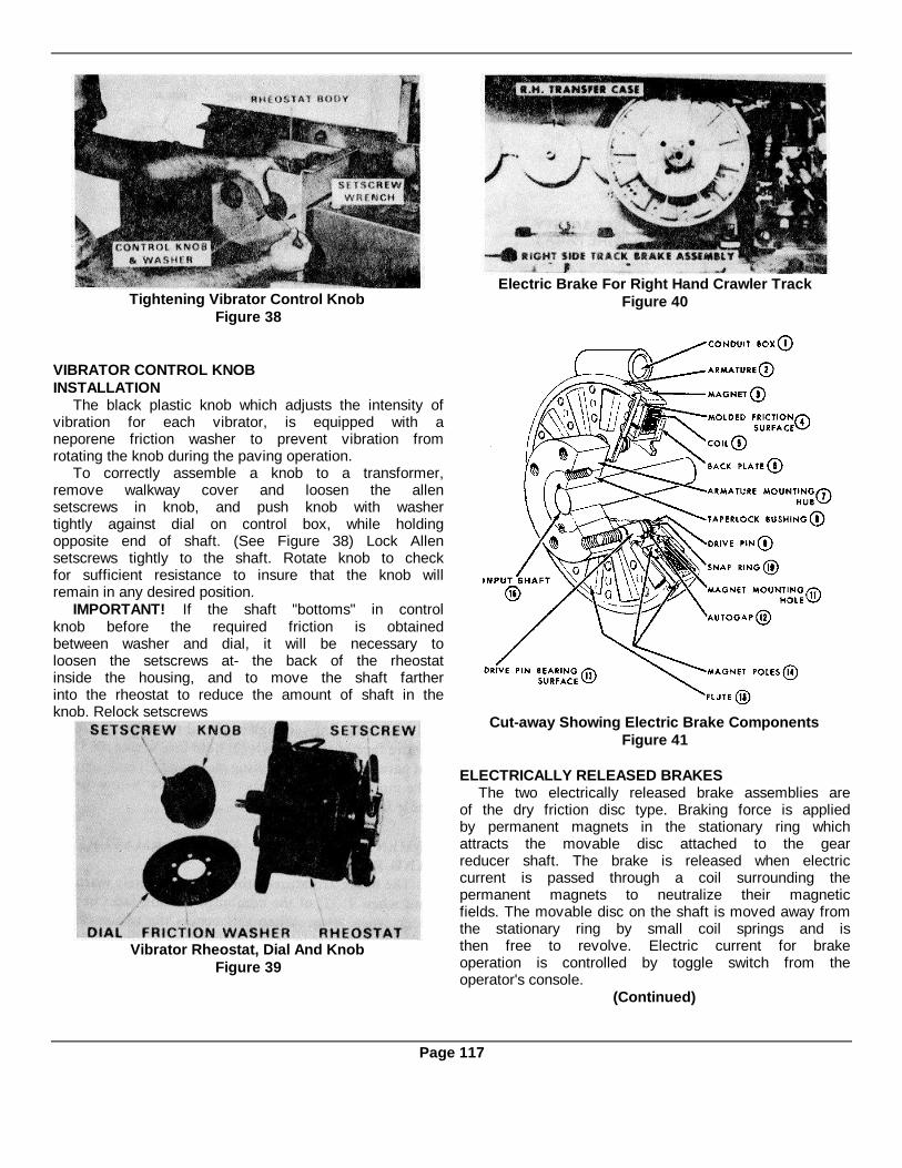
Tightening Vibrator Control KnobFigure 38
VIBRATOR CONTROL KNOBINSTALLATION
The black plastic knob which adjusts the intensity ofvibration for each vibrator, is equipped with aneporene friction washer to prevent vibration fromrotating the knob during the paving operation.
To correctly assemble a knob to a transformer,remove walkway cover and loosen the allensetscrews in knob, and push knob with washertightly against dial on control box, while holdingopposite end of shaft. (See Figure 38) Lock Allensetscrews tightly to the shaft. Rotate knob to checkfor sufficient resistance to insure that the knob willremain in any desired position.
IMPORTANT! If the shaft "bottoms" in controlknob before the required friction is obtainedbetween washer and dial, it will be necessary toloosen the setscrews at- the back of the rheostatinside the housing, and to move the shaft fartherinto the rheostat to reduce the amount of shaft in theknob. Relock setscrews
Vibrator Rheostat, Dial And KnobFigure 39
Electric Brake For Right Hand Crawler TrackFigure 40
Cut-away Showing Electric Brake ComponentsFigure 41
ELECTRICALLY RELEASED BRAKESThe two electrically released brake assemblies are
of the dry friction disc type. Braking force is appliedby permanent magnets in the stationary ring whichattracts the movable disc attached to the gearreducer shaft. The brake is released when electriccurrent is passed through a coil surrounding thepermanent magnets to neutralize their magneticfields. The movable disc on the shaft is moved away fromthe stationary ring by small coil springs and isthen free to revolve. Electric current for brakeoperation is controlled by toggle switch from theoperator's console.
(Continued)
Page 117

Detail Of Brake Auto-gap Drive PinFigure 42
(Refer to Figures 41 & 42 for Part Identification)The magnet ring (3) is bolted to the paver track
drive gear case, with the case input shaft extension(16) passing through the ring but not attached to it.This ring contains the permanent magnets and thewindings of the electro magnet. Its outer faceincludes the friction surface (4). Armature (2) is themovable disc which is loosely held by four drive pins(9) and coil springs. These pins project from hub (7)which is keyed to the input shaft extension from thegear case. The armature (2) is free to move laterallyalong the shaft but is slaved to the shaft by the drivepins. The permanent magnets therefore draw thearmature tight against the friction face (4) of thestationary magnet ring (3). This prevents anymovement of the armature and consequently anyrotation of the gear case shaft.
Small coil springs on the drive pins (9) arecompressed when the armature is held by thepermanent magnets. When the brakes are to bereleased the operator moves the console toggleswitch to Neutral or Travel. Electric current thenenergizes the electro magnetic coil in the magnetring (3) and neutralizes the magnetic attraction ofthe permanent magnets. The coil springs on thedrive pins force the armature (2) away from thefrictioi face on the magnet ring and the armatureand gear case shaft are then free to rotate. When thebrake switch is at Neutral or Travel there mustalways be a clearance between the armature and themagnet ring friction face.
As the friction faces wear from repeatedapplication of the brake, the gap between themincreases. The desired gap of 1/16" should bemaintained by adjustment of the armature hub (7)and its taper-lock bushing (8) on shaft (16).
Detail Of Drive Pin Safety WiringFigure 43
DRIVE PIN SAFETY WIRINGWhenever the safety wire on brake drive pins (9) is
removed, it should be restored before the brake isagain operated. See details in Figure 43.
Brake Armature ClearanceAutomatic wear adjustment, or armature follow-
up, is provided by allowing the armature to slidefreely axially on the drive pins. (See Figure 42). Thisprovides maximum armature life with a minimumamount of care and attention. As the frictionsurfaces "wear in" the armature advances on thepins so full contact with magnet is maintained at alltimes.
Wear PatternWear grooves appear on the armature and
magnet surfaces after extended service, (Figure 41).This is a normal wear condition and will not impairfunctioning of the unit or cause it to lose torque. Infact, a new brake may require burnishing, orrunning-in, before maximum rated torque may bedeveloped. Never machine the armature or magnetcontact surfaces to remove grooving or scoring.
Remachining the face of a worn armature is neverrecommended. But a worn magnet face shouldalways be machined if it is to be used with areplacement armature. In refacing a worn magnet:
(1) machine only enough material to clean up theentire face of the magnet; (2) hold face within .005"of parallel with the mounting plate; and (3) undercutthe molded facing material .002" to .004" below thepole faces.
WHEN TO REPLACE WORN ARMATUREAND ROTOR
The brake armature-rotor set is completely wornout when 9/32" of the combined friction faces hasbeen worn away. When this occurs the two partsmust be replaced in order to avoid brake slippage ata critical time.
Page 118

Method Of Measuring Wear Of Electric BrakeFigure 44
The simple and accurate wear check is made bymeasuring the combined thickness of Magnet (3)and Armature (2) when the armature is pressed tightagainst the magnet. (See Figures 44 & 45) Whenboth parts are new, dimension Y will be 3-1/16".When completely worn-out, Y will be 2-3/4". Besure that the console switch is at, BRAKE so that thearmature is held tight against the rotor when themeasurement is taken.
Side View Brake Showing Wear-check DimensionFigure 45
Cross-section Thru Electric Brake Magnet AssemblyFigure 46
BRAKE ELECTRICAL MODULEThe electrically released brake system includes a
plug-in relay and E.M.F. bleeder module located inthe main electric panel. The relay is for ON-OFFpower application by remote control switch. Thebleeder is for electromotive force dissipation whenthe power contacts open. (See Figure 47)
Adjustment of the brake release point is coveredby Figure 48.
Location Of Brake Relays & E.M.F. BleederFigure 47
Variable Resistor For Brake Release AdjustmentFigure 48
Page 119

Figure 49
COMPOPNENT PARTS IDENTIFICATION - TWIN DISC C-110 CLUTCH
Ref. Ref.No. Description Qty. No Description Qty1 Hub & Back Plate 1 10 Lever Link Pin 82 Adjusting Yoke 1 11 Cone Collar 13 Finger Lever 4 12 Bolt 24 Lever Pin 4 13 Nut 25 Cotter Pin 4 14 Cotter Pin 86 Adjusting Lock Pin 1 15 Washer (Collar) 47 Adjusting Lock Pin Spring 1 16 Driving Plate (3 Segments Each) 18 Sliding Sleeve 1 17 Floating Plate 19 Lever Link 8 18 Release Spring 6
COMPONENT PART IDENTIFICATION - POWER TAKE-OFF ASSEMBLY (FIGURE 50)
Ref. Ref.No. Description Qty. No Description Qty
1 Driving Ring 1 15 Shaft 12 Yoke, Throw Out 1 16 Seal, Oil 23 Key 1 17 Gasket 14 Grease Line 1 18 Instruction Plate,Clutch Adjustment 15 Lockwasher 1 19 Snap Ring 16 Locknut 1 20 Clutch, Twin Disc Model C-1107 Bearing 1 (See above parts identification list)8 Shaft, Clutch 1 21 Fitting, Grease 29 Handle 2 22 Fitting, Grease 210 Key 2 23 Lube Line - Shaft Bearing 111 Bell Housing 1 24 Lube Line - Yoke Throw Out13 Bearing 1 Bearing 114 Cover 1 25 Capscrew (Nylock) 8
Page 120

Clutch Adjustment (See Figure 49)(a) Shift 24 Speed Transmission to Neutral. Stop
engine and remove ignition key.(b) Remove inspection door from Bell Housing
(11). Dis-engage clutch.(c) Rotate clutch by means of generator V-belt
until Lock Pin (6) is accessible.(d) Pull out Lock Pin (6) and insert wire or nail to
hold it disengaged.(e) Hold generator V-belt so that Shaft (15)
cannot turn.(f) Turn the Yoke and Sleeve Assemblies (2) & (8)
clockwise to reduce slippage when clutch is engaged,or counterclockwise to increase clearance whenclutch is dis-engaged.
(g) Release Lock Pin (6) to hold the setting, butbe sure the Pin enters one of the locking grooves.
Power Take-off & Clutch Assembly for GM Diesel EngineFigure 50
Page 121
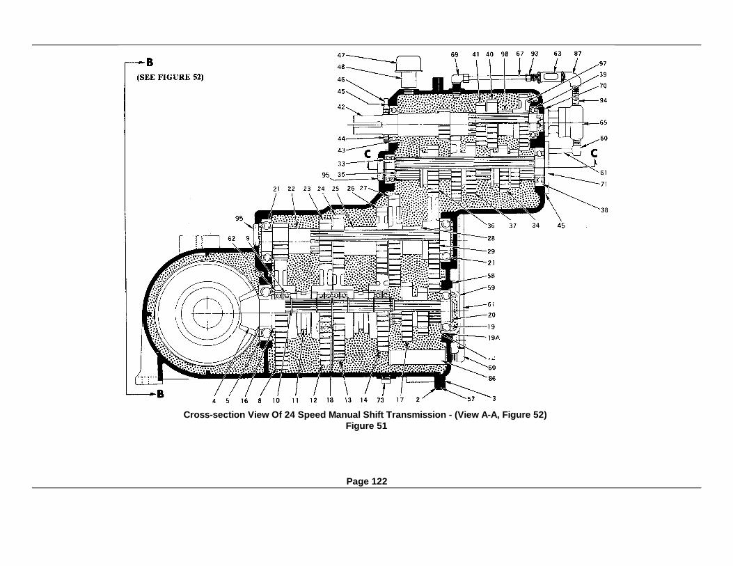
Cross-section View Of 24 Speed Manual Shift Transmission - (View A-A, Figure 52)Figure 51
Page 122
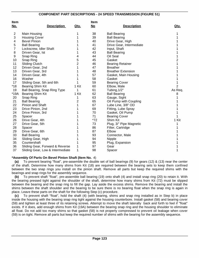
COMPONENT PART DESCRIPTIONS - 24 SPEED TRANSMISSION (FIGURE 51)
Item ItemNo. Description Qty. No Description Qty.
2 Main Housing 1 38 Ball Bearing 13 Housing Cover 1 39 Ball Bearing 14 Bevel Pinion 1 40 Drive Gear, High 15 Ball Bearing 1 41 Drive Gear, Intermediate 17 Lockscrew, Idler Shaft 1 42 Input, Shaft 18 Driven Gear, Ist 1 43 Ball Bearing 19 Snap Ring 4 44 Oil Seal 110 Snap Ring 5 45 Gasket 211 Sliding Clutch 2 46 Bearing Retainer 112 Driven Gear, 2nd 1 47 Breather 113 Driven Gear, 3rd 1 48 Breather Extension 114 Driven Gear, 4th 1 57 Gasket, Main Housing 116 Washer 1 58 Gasket 117 Sliding Gear, 5th and 6th 1 59 Bearing Cover 1
*18 Bearing Shim Kit 1 Kit 60 Elbow, Male 219 Ball Bearing, Snap Ring Type 1 61 Tubing,1/2" As Req.
*19A Bearing Shim Kit 1 Kit 62 Ball Bearing 820 Snap Ring 1 63 Gauge, Sight 121 Ball Bearing 2 65 Oil Pump with Coupling 122 Pinion and Shaft 1 67 Lube Line, 3/8" OD 123 Drive Pinion, 2nd 1 69 Fitting, Lube Spray 124 Drive Pinion, 3rd 1 70 Gasket, Oil Pump 125 Spacer 1 71 Bearing Cover 126 Drive Gear, 4th 1 *72 Shim Kit 1 Kit27 Drive Gear, 5th 1 73 Plug, 3/" Pipe Magnetic 128 Spacer 1 86 Filter, Cartridge 129 Drive Gear, 6th 1 87 Elbow 133 Ball Bearing 1 93 Connector, Male 134 Sliding Gear, High 1 94 Nipple 135 Countershaft 1 95 Plug, Expansion 136 Sliding Gear, Forward & Reverse 1 97 Gear 137 Sliding Gear, Low & Intermediate 1 98 Spacer 1
*Assembly Of Parts On Bevel Pinion Shaft (Item No. 4)(a) To prevent bearing "float", pre-assemble the double set of ball bearings (9) for gears (12) & (13) near the center
of the shaft. Determine how many shims from Kit (18) are required between the bearing sets to keep them confinedbetween the two snap rings you install on the pinion shaft. Remove all parts but keep the required shims with thebearings and snap rings for the assembly sequence.
(b) To prevent shaft "float", pre-assemble ball bearing (19) onto shaft (4) and install snap ring (20) to retain it. Withthe bearing pressed tight against the shoulder of the shaft, determine how many shims from Kit (72) must be slippedbetween the bearing and the snap ring to fill the gap. Lay aside the excess shims. Remove the bearing and install theshims between the shaft shoulder and the bearing to be sure there is no bearing float when the snap ring is again inplace. Leave these parts on the shaft for the following Step (c) procedure.
(c) To prevent shaft "float", hold the shaft (4) (with bearing, shims and snap ring installed as in Step b) in placeinside the housing with the bearing snap ring tight against the housing counterbore. Install gasket (58) and bearing cover(59) and tighten at least three of its retaining screws. Attempt to move the shaft laterally back and forth to feel if "float"exists. If it does, add enough shims from Kit (19A) between the bearing snap ring and the housing shoulder to eliminateall float. Do not add too many shims so that gasket (58) is not properly compressed to prevent oil leakage when cover(59) is on tight. Remove all parts but keep the required number of shims with the bearing for the assembly sequence.
Page 123
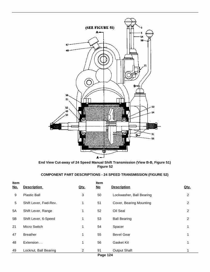
End View Cut-away of 24 Speed Manual Shift Transmission (View B-B, Figure 51)Figure 52
COMPONENT PART DESCRIPTIONS - 24 SPEED TRANSMISSION (FIGURE 52)
Item ItemNo. Description Qty. No Description Qty.
9 Plastic Ball 3 50 Lockwasher, Ball Bearing 2
5 Shift Lever, Fwd-Rev. 1 51 Cover, Bearing Mounting 2
5A Shift Lever, Range 1 52 Oil Seal 2
5B Shift Lever, 6-Speed 1 53 Ball Bearing 2
21 Micro Switch 1 54 Spacer 1
47 Breather 1 55 Bevel Gear 1
48 Extension . . 1 56 Gasket Kit 1
49 Locknut, Ball Bearing 2 91 Output Shaft 1Page 124

Cross-section View of 24 Speed Manual shift Transmission (View C-C, Figure 51)Figure 53
COMPONENT PART DESCRIPTIONS - 24 SPEED TRANSMISSION (FIGURE 53)
Item ItemNo. Description Qty. No Description Qty.
1 Housing, Fwd-Rev. Shift 1 21A Micro Switch 11A Housing, Range Shift 1 23 Jam Nut 22 Gasket 1 24 Retaining Screw 17 Lockscrew, Idler Shaft 1 24A Expansion Plug 210 Shaft, Fwd-Rev. 1 25 Detent Spring I
10A Shaft, Range 1 30 Ball Bearing 210B Shaft, Low & Intermediate 1 31 Shaft, Idler Gear 111 Shift Fork, Fwd-Rev. 1 32 Idler Gear, Reverse 112 Oil Seal 1 33 Ball Bearing 1
12A Expansion Plug 2 34 Sliding Gear, High 113 Detent Ball 1 35 Countershaft 1
13A Shift Fork, High 1 36 Sliding Gear, Fwd-Rev. 114 Detent Spring 1 37 Sliding Gear, Low & Intermediate 1
14A Shift Fork, Low & Intermediate 1 38 Ball Bearing 117 Capscrew 1 45 Gasket I
17A Detent Ball 1 71 Cover for Bearing I18 Retaining Screw 1 95 Expansion Plug 121 Capscrew 1
Page 125

Side & End View Cross-sections Of 6 Speed Shift Lever ModuleFigure 54
126

COMPONENT PART DESCRIPTIONS - 24 SPEED TRANSMISSION (FIGURE 54)
Item ItemNo. Description Qty. No Description Qty.
1 Housing 1 19 Plug 12 Gasket 1 20 Plunger, Locking 43 Gasket, Shifter Cover 1 21 Spring 24 Cover, Shifter 1 22 Ball 35 Shift Lever, Six Speed 1 23 Pin 16 Spring, Shift Shaft 1 24 Expansion Plug 37 Washer, Shift Cap 1 28 Retainer, Spring 38 Cap, Shift Housing 1 29 Spring 39 Ball, Shift Lever 1 30 Nut 3
10 Shifter Shaft, 5th & 6th 1 32 Pin, Groove 311 Shifter Shaft, 3rd & 4th 1 33 Boot, Cover 112 Shifter Shaft, 1st & 2nd 1 34 Clamp, Boot 113 Shifter Dog, 5th & 6th 1 36 Collar, Shifter Stop 114 Fork, 5th & 6th 1 37 Pin, Roll 115 Fork, 3rd & 4th 116 Shifter Dog, 1st & 2nd 117 Fork, 1st & 2ND 1
REPLACEMENT OF TRANSMISSION OIL PUMPThe paver is equipped with an oil pump on front end of transmission. (Item 65, Figure 51)This pump provides positive
lubrication circulation to gears and bearing in the main transmission.
If it should be necessary to replace pump, it is important that it be properly mounted.
Failure to follow this assembly procedure can result in premature failure of the pump.METHOD:
1. Check condition of upper shaft bearings in transmission. A slight lateral movement of shaft should be possible ifbearings and shah are in acceptable operating condition.
2. Inspect pump coupling for wear and make sure it will slide freely on pump shaft. Also, inspect driving slot forcoupling in transmission shaft. Replace parts if worn.
3. Assemble pump to transmission and only finger tighten bolts. Fill pump with the recommended transmissionlubricant.
4. Attach lube lines to pump. Do not completely tighten lines so that the pump will be free to align itself to thetransmission while rotating.
5. Start engine and engage clutch. While pump is operating , tighten mounting capscrews evenly andprogressively.
6. Tighten lube lines securely.7.
TRANSMISSION OIL LINE FILTERA fine mesh filter screen is used ahead of the oil supply line of the transmission pump to keep the foreign particles
from damaging the pump. This filter is a cartridge type unit which is screwed into the transmission housing. The oil pumpsuction line fitting is then screwed into the center of the filter cartridge. (Item 86, Figure 51)
If an oil pump in apparent good condition fails to maintain a good flow of oil through the sight glass, a plugged filterscreen may be responsible. If this is suspected, back-flush the strainer and transmission case as follows:
1. Disconnect the suction line to the pump and attach a hose and funnel so that flushing solution can be poured intothe line.
2. Drain the transmission oil, then re-install the drain plug.3. Pour a quantity of Texaco Rando AA flushing solution into the gear case through the pump suction line to
back-flush the filter screen. Fill the case to a point above the normal oil level (on dipstick) and allow several hours for thesolution to dissolve the oil residue.
(Continued)Page 127

Transmission Oiling system - Exploded ViewFigure 55
4. Drain the flushing solution.5. With the drain plug removed, pour someadditional fresh solution into the pump lines as afinal flushing of the screen.6. Re-attach line. Replace drain plug. Fill caseto proper level with Texaco #EP90 Universal GearLubricant (about 17 quarts) and test pump forproper flow through sight glass.
NOTE: The filter screen flushing procedureis recommended as a seasonal lubricationrequirement in keeping with goodequipment maintenance programs. Wherenormally gear cases are drained, flushed,and re-filled with fresh lubricant for anupcoming season, this procedure variesonly in that the flushing solution is pouredinto the case through the pump suction lineso that the filter screen back-flush occursautomatically.
LOSS OF GENERATOR VOLTAGE (125 V.A.C.)Occasionally, Winpower 3600 RPM generator
will lose its residual magnetism and fail to produceAC power. This is very unusual, unless thegenerator has been dis-assembled, or has received asevere jolt. In such a case it will be necessary to"flash the field" in order for the generator to againproduce power.
To 'flash the field" a step-down transformerwith a nominal 125 V.A.C. primary winding and a12 to 30 volt secondary winding can be used. A12.6 volt filament transformer will also do the job.(See Figure 56).
The transformer primary should have a cordwith a plug for a 125 V.A.C. wall receptical. The
Method Of Flashing 125 V AC GeneratorFigure 56
secondary should have extension leads with insulatedprobes.
METHOD: With the generator rotating atproper speed, plug the transformer into any"Hot" 125 VAC outlet and touch the probesto L1 & L2 connections at the junction boxon the generator. A momentary contact isall that is required.
GENERATOR MAINTENANCELittle maintenance is required other than routine inspectionand cleaning. The bearings are prelubricated and will be along life item unless damaged by accident or excessivedriving belt tension.The interior of the generator should be clean andunobstructed. Slip rings and brushholders should be keptfree from dirt, oil, and moisture. If compressed air isavailable it can be used effectively for cleaning.
Page 128
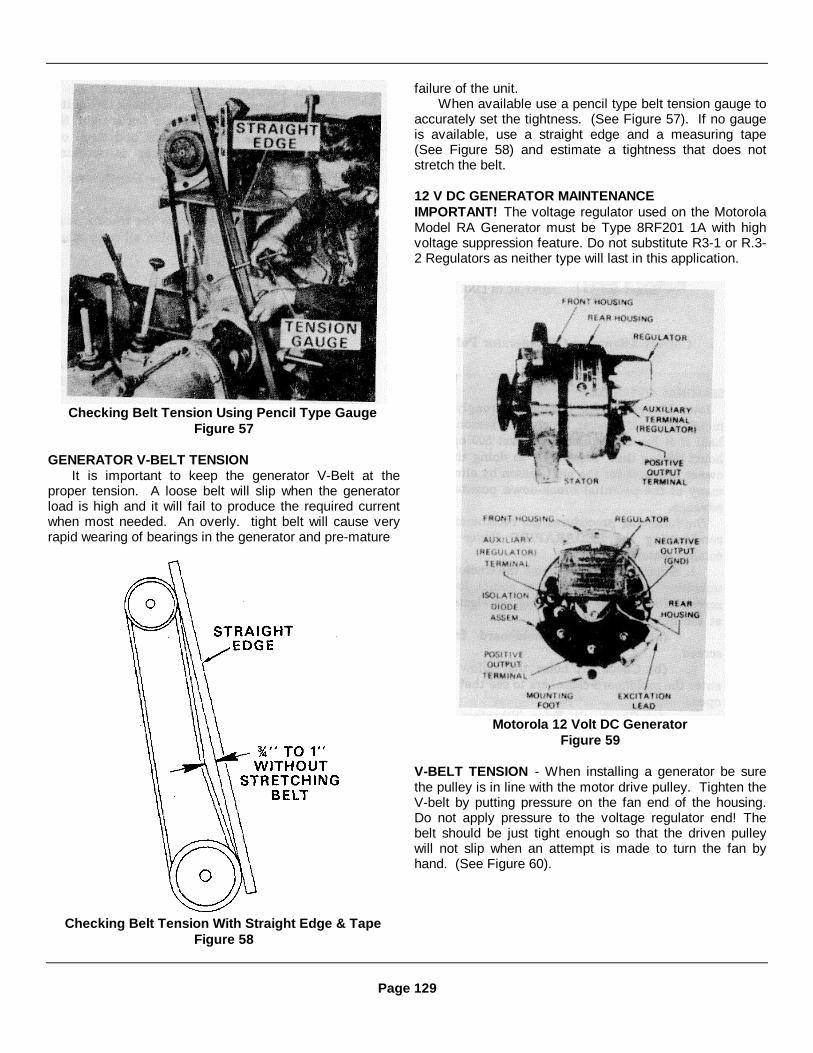
Checking Belt Tension Using Pencil Type GaugeFigure 57
GENERATOR V-BELT TENSIONIt is important to keep the generator V-Belt at the
proper tension. A loose belt will slip when the generatorload is high and it will fail to produce the required currentwhen most needed. An overly. tight belt will cause veryrapid wearing of bearings in the generator and pre-mature
Checking Belt Tension With Straight Edge & TapeFigure 58
failure of the unit.When available use a pencil type belt tension gauge to
accurately set the tightness. (See Figure 57). If no gaugeis available, use a straight edge and a measuring tape(See Figure 58) and estimate a tightness that does notstretch the belt.
12 V DC GENERATOR MAINTENANCEIMPORTANT! The voltage regulator used on the MotorolaModel RA Generator must be Type 8RF201 1A with highvoltage suppression feature. Do not substitute R3-1 or R.3-2 Regulators as neither type will last in this application.
Motorola 12 Volt DC GeneratorFigure 59
V-BELT TENSION - When installing a generator be surethe pulley is in line with the motor drive pulley. Tighten theV-belt by putting pressure on the fan end of the housing.Do not apply pressure to the voltage regulator end! Thebelt should be just tight enough so that the driven pulleywill not slip when an attempt is made to turn the fan byhand. (See Figure 60).
Page 129

Correct Alignment of Generator PulleyFigure 60
SEASONAL OVERHAULIowa Manufacturing Company strongly recommends
that each paver be given a seasonal overhaul if it hasaccumulated at least 500 operating hours during thatseason. By so doing the paver owner prepares for the nextseason by eliminating many of the potential break-downpossibilities in advance.
The following procedures are recommended forconditioning the CEDARAPIDS Paver for the comingseason.
1. Separate the screed from the tractor unit byunbolting the arm at the pivot points, loosen the screedlifting cables and unplug the electric cable at the quick-disconnect.
(a) Remove the moldboard from the screed.(b) Check all holes that allow heat to enter the
moldboard chambers to see that they are open.(c) Check all Eriez Vibrators for the proper
setting. Follow procedure as outlined in Section 7.(d) Check all wiring and connections to make
sure they are not broken or bare. Take care to check theheavy crossover cable.
(e) Check the screed plate thickness and lookfor cracks.
(f) Disassemble the depth control screws andsocket. Clean out and check for wear and excessivelooseness in these sockets, which could cause a wavy mat.
(g) Clean out the heater fuel tank.(h) Clean out the heater; check the igniter tip
and porcelain. Be sure blower fan is tight. Set tips asoutlined in manual. Check and clean out pump. Be surethe transformer is working.
WARNING: Cover must be over transformer atall times.
2. Check over all wiring on the tractor, looking forloose or bare wire. Tighten all connections on:
(a) Relays(b) Toggle switches(c) Limit switch on the reverse shifter bar(d) Depth control limit switches(e) Manual override switch(f) Check the 125 volt generator V-belt drive
and mounting. Check pulley set screws for tightness.(g) Check the 12 VDC Generator V-belt drive
and mounting. Check pulley set screws for tightness.3. Refer to the engine manufacturer's manual
for all periodic maintenance instructions. Strict compliancewith these instructions will help assure steady and efficientoperation of the vital power plant.
4. Drain and flush the transmission and transfercases and fill with the correct quantity and type of oil.
5. Check electric clutches - make sure eachclutch is getting the proper amount of current. This shouldbe a minimum of 11.4 volts when machine is in operation.Make sure all clutch settings are maintained as noted inElectric Clutch Paragraphs, this Section.
6. Remove the slat and screw conveyors.(a) The liners for the slat conveyor may need
replacing.(b) If the chain of the slat conveyor is starting
to show wear it may be reversed.(c) Check the conveyor sprockets if they show
excess wear, replace at this time.(d) Check all the roller bearings and tighten all
hold down bolts.(e) The outboard bearing for the screw
conveyor may need replacing.(f) Hardface the screw conveyor. An extra
hardfaced screw conveyor should be kept in stock. As theone on the machine starts to show wear, it should bereplaced and built back up with hardface.
Page 130

7. Remove track, upper lower, and oscillating rollers. Replace all track roller shafts that show wear. The rollerscan be rebushed if the bore is not damaged. It the bore is damaged either a new roller is needed or a salvage operationcan be performed by boring the roller oversize and pressing in a steel sleeve. For bore sizes, consult Iowa Manu-facturing Company, Service Engineering Department.
(a) Check the sprockets and shoes.(b) Clean out the guard around the track drive chain.(c) Check the bolts which hold the flange drive sprocket to the rear track drive sprocket. Make sure they are
S.A.E. bolts with a double jam nut and tightened properly.8. Drain hydraulic fluid reservoir. Clean tank and suction filter. Re-fill with fresh fluid. (See Section 5)
Page 131

SECTION XII
Purchased Component Vendor Instructions
Page 133

PART IV.
VANE PUMPS
V100, V200, V300, V400
V500, AND V2P SERIES

TABLE OF CONTENTS
Section PageI INTRODUCTION
A. Purpose of Manual ..................................................................................................... 2B. General Information ................................................................................................... 2
II DESCRIPTIONA. General ............................... ...................................................................................... . 4B. Assembly and Construction ................... .................................................................... 4C. Flow Control and Relief Valve ................ ................................................................... 4D. Application ............................. ................................................................................... 4
III PRINCIPLES OF OPERATIONA. Pumping Cartridge ..................................................................................................... 4B. Hydraulic Balance ...................................................................................................... 5C. Pressure Plate ........................... ................................................................................ 5D. Flow Control and Relief Valve ................ ................................................................... 5
IV INSTALLATION AND OPERATING INSTRUCTIONSA. Installation Drawings .................................................................................................. 6B. Drive Connections ..................................................................................................... 6C. Shaft Rotation ............................. .............................................................................. 6D. Piping and Tubing ......................... ............................................................................ 6E. Hydraulic Fluid Recommendations ............................................................................. 6F. Overload Protection.................................................................................................... 7G. Port Positions............................................................................................................. 7H. Start-Up...................................................................................................................... 8
V SERVICE INSPECTION AND MAINTENANCEA. Service Tools ............................................................................................................. 8B. Inspection ................................................................................................................... 8C. Adding Fluid To The System .................. .................................................................. 8D. Adjustments ............................. ................................................................................. 8E. Lubrication ................................................................................................................. 8F. Replacement Parts ......................... ........................................................................... 8G. Trouble-Shooting........................................................................................................ 8
VI OVERHAULA. General ................................ ..................................................................................... 10B. Disassembly ............................. ................................................................................. 10C. Inspection and Repair ................................................................................................ 10D. Assembly ................................................................................................................... 11
VII TESTING................................................................................................................................. 11
1

Section I - INTRODUCTION
A. PURPOSE OF MANUALThis manual has been prepared to assist the users of Vickers balanced vane type hydraulic single pumps in properly
installing, maintaining and repairing their units. In the sections which follow, the single pumps are described in detail,their theory of operation is discussed and instructions are given for their proper installation, maintenance and overhaul.
The general series of models covered are V100, V200, V300, V400, V500 and V2P. The information given applies tothe latest design configurations listed in Table I. Earlier designs are covered only insofar as they are similar to thepresent equipment.
B. GENERAL INFORMATION1. Related Publications - Service parts information and installation dimensions are not contained in this manual.
The parts catalogs and installation drawings listed in Table I are available from any Vickers Mobile Division ApplicationEngineering office, or from:
VickersMobile Hydraulics DivisionProduct Service DepartmentP.O. Box 302, Troy, Michigan
2. Model Codes - There are many variations within each basic model series, which are covered by variables in themodel code. Table II is a complete breakdown of the code covering these units. Service inquiries should always includethe complete unit model number, which is stamped on the pump cover.
TABLE IPARTS CATALOGS AND INSTALLATION DRAWINGS
MODEL DESIGN NO. PARTS INSTALLATIONSERIES (See Table II) CATALOG DRAWING
V100 -10 M-2031-S M-152060V200 -12 M-1771-S M-190082V300 -11 M-2033-S M-128797V400 M-127065V500 -10 M-1262-S M-236696V2P -10 M-2002-S M-289405
Figure 1
2
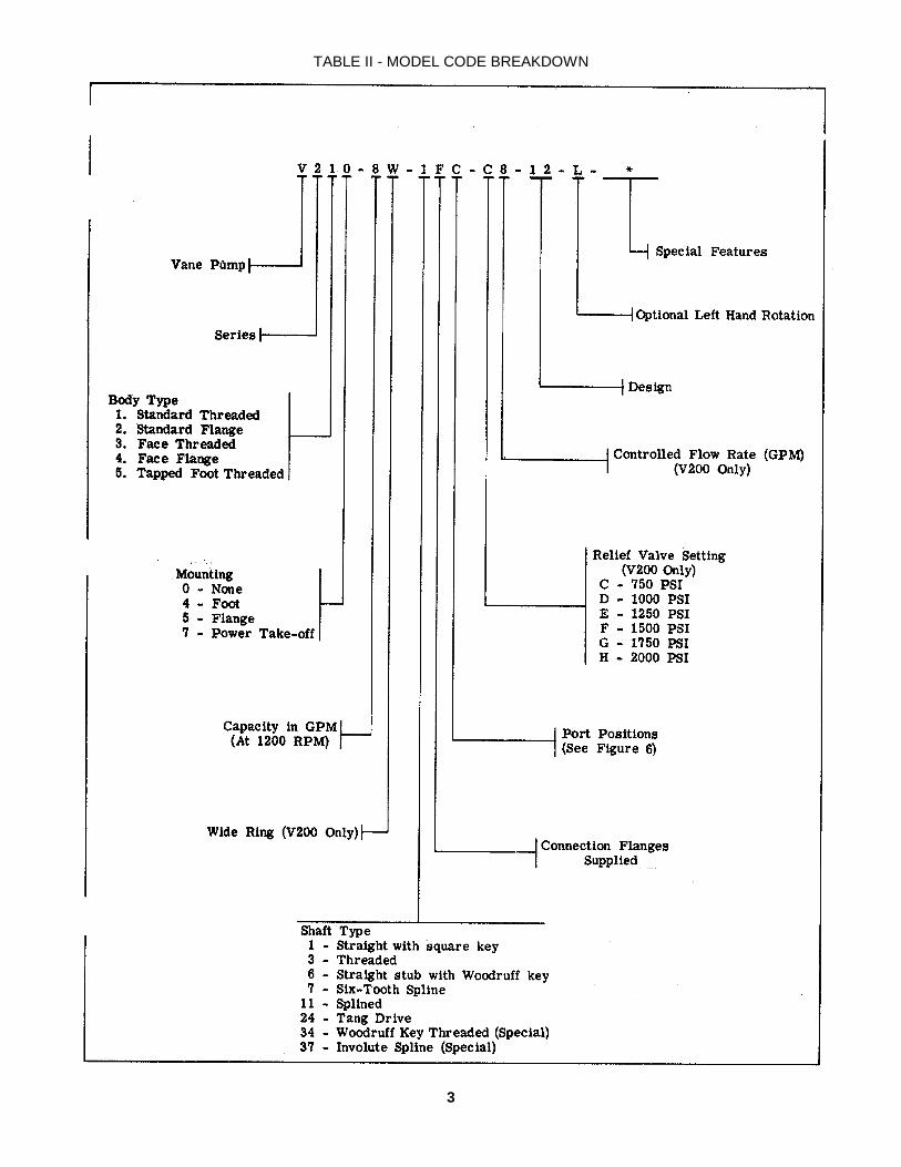
TABLE II - MODEL CODE BREAKDOWN
3

Section II - DESCRIPTION
A. GENERAL
Pumps in this series are used to develop hydraulic fluidflow for the operation of Mobile equipment. The positivedisplacement pumping cartridges are the rotary vane typewith shaft side loads hydraulically balanced. The flow ratedepends on the pump size and the speed at which it isdriven.
All units are designed so that the direction of rotation,pumping capacity and port positions can be readilychanged to suit particular applications.
B. ASSEMBLY AND CONSTRUCTION
The V200 series pump illustrated in cutaway in Figure1 is representative of all single pumps in this series. Theunit consists principally of a ported body and cover, a driveshaft supported by two ball bearings, a pumping cartridgeand a pressure plate. The components of the cartridge arean elliptical ring, a slotted rotor splined to the drive shaftand twelve vanes fitted to the rotor slots.
As the rotor is driven by the driveshaft, the vanes generatefluid flow by carrying fluid around the elliptical ring contour(see section m). Fluid enters the cartridge through theinlet port in the body and is discharged through thepressure plate to the outlet port in the cover.
C. FLOW CONTROL AND RELIEF VALVE
V200 pumps are available with an integr Flow Controland Relief Valve in the pump cover. This limits the fluidflow in the system to a maximum prescribed rate andprevents excessive pressure build-up. Fluid not requiredin the system is recirculated to tank.
D. APPLICATION
Pump ratings in GPM as shown in the model coding are at1200 RPM. For ratings at other speeds, methods ofinstallation and other application information, VickersMobile Division Application engineering personnel shouldbe consulted.
Section III - PRINCIPLES OF OPERATION
A. PUMPING CARTRIDGE
As mentioned in Section II;, fluid flow is developed inthe pumping cartridge. The action of the cartridge isillustrated in Figure 2. The rotor is driven within the ring bythe driveshaft, which is coupled to a power source. Asthe rotor turns, centrifugal force on the vanes causes themto follow the elliptical inner surface of the ring.
Radial movement of the vanes and turning of the rotorcause the chamber between the vanes to increase as thevanes pass the inlet sections of the ring. This results in alow pressure condition which allows atmospheric pressureto force fluid into the chambers. (Fluid outside the inlet isat atmospheric pressure or higher.)
Figure 2
4

This fluid is trapped between the vanes and carried pastthe large diameter or dwell section of the ring. As theoutlet section is approached, the ring diameter decreasesand the fluid is forced out into the system. Systempressure is fed under the vanes, assuring their sealingcontact against the ring during normal operation.
B. HYDRAULIC BALANCE
The pump ring is shaped so that the two pumpingchambers are formed diametrically opposed. Thus,hydraulic forces which would impose side loads on theshaft cancel each other out.
C. PRESSURE PLATE
The pressure plate seals the pumping chamber as shown inFigure 3. A light spring holds the plate against thecartridge until pressure builds up in the system. Systempressure is effective against the area at the back of theplate, which is larger than the area exposed to the pumpingcartridge. Thus, an unbalanced force holds the plateagainst the cartridge, sealing the cartridge and providingthe proper running clearance for the rotor and vanes.
D. FLOW CONTROL AND RELIEF VALVE
1. Maximum pump delivery and maximum systempressure are determined by the integral flow control and'relief valve in a special outlet cover used on some V200pumps. This feature is illustrated schematically in Figure4. An orifice in the cover limits maximum flow. A pilot-operated type relief valve shifts to divert excess fluid de-livery to tank, thus limiting the system pressure to aprescribed maximum.
2. Figure 4A shows the condition when the total pumpdelivery can be passed through the orifice.
Figure 3
This condition usually occurs only at low drive speeds.The large spring chamber is connected to the pressureport through an orifice. Pressure in this chamber equalizespressure at the other end of the relief valve spool and thelight spring holds the spool closed. Pump delivery isblocked from the tank port by the spool land.
3. When pump delivery is more than the flow ratedetermined by the orifice plug, a pressure build-up forcesthe spool open against the light spring. Excess fluid isthrottled past the spool to the tank port as shown in Figure4B.
4. If pressure in the system builds up to the reliefvalve setting (Figure 4C), the pilot poppet is forced off itsseat. Fluid in the large spring chamber flows through thespool and out to tank. This flow causes a pressuredifferential on the spool, shifting it against the light spring.All pump delivery is thus permitted to flow to tank.
Figure 4
5

Section IV- INSTALLATION and OPERATING INSTRUCTIONS
A. INSTALLATION DRAWINGS
B. DRIVE CONNECTIONS
CAUTION
Vickers pump shafts are designed to be installed incouplings, pulleys, etc., with a slip fit or very lighttap. Pounding can injure the bearings. Shafttolerances are shown on the pump installationdrawings. (See Table I.)
1. Direct Mounting - A pilot on the pump mountingflange (Figure 5) assures correct mounting and shaft
Figure 5
and shaft alignment, provided the pilot is firmly seated inthe accessory pad of the power source. Care should beexercised in tightening all flange mounting screws toprevent misalignment.
If gaskets are used between flanges, they should beinstalled carefully so as to lay flat. Shaft keys andcouplings must be properly seated to avoid slipping andpossible shearing.
2. Indirect Drive - Chain, spur gear or vee beltpulley drives may also be used with these pumps. Flatbelt drives are not recommended because of thepossibility of slipping.
To prevent excessive side loads on the pumpbearings, it is important to check for correct alignmentand guard against excessive belt or chain tension.
C. SHAFT ROTATION
Vickers pumps are normally assembled for righthand(clockwise) rotation as viewed from the shaft ends. Apump made for lefthand rotation is identified by an "L" inthe model code (See Table II).
NOTE
These pumps must be driven in the direction of thearrows cast on the pump ring. If it is desired to changethe direction of drive rotation, it is necessary to reversethe ring. (See Section VI-B-D and Figure 9. )
CAUTION
Never drive a pump in the wrong direction of rotation.Seizure may result, necessitating expensive repairs.
D. PIPING AND TUBING
1. All pipes and tubing must be thoroughly cleanedbefore installation. Recommended methods of cleaningare sand blasting, wire brushing and pickling.
NOTE
For instructions on pickling refer to Vickers instructionsheet M-9600.
2. To minimize flow resistance and the possibility ofleakage, only as many fittings and connections as arenecessary for proper installation should be used.
3. The number of bends in tubing should be kept to aminimum to prevent excessive turbulence and friction ofoil flow. Tubing must not be bent too sharply. Therecommended radius for bends is three times the insidediameter of the tube.
E. HYDRAULIC FLUID RECOMMENDATIONS
The oil in a hydraulic system serves as the powertransmission medium. It is also the system's lubricant andcoolant. Selection of the proper oil is a requirement forsatisfactory system performance and life. Oil must beselected with care and with the assistance of a reputablesupplier.
TWO IMPORTANT FACTORS IN SELECTING AN OILARE:
1. Antiwear Additives - The oil selected must containthe necessary additives to insure high anti-wearcharacteristics.
2. Viscosity - The oil selected must have properviscosity to maintain adequate lubricating film at systemoperating temperature.
SUITABLE TYPES OF OIL ARE:
1. Crankcase Oil meeting API service classificationMS. The MS (most severe) classification is the key toproper selection of crankcase oils for Mobile hydraulicsystems.
6

2. Antiwear Type Hydraulic Oil - There is no commondesignation for oils of this type. However, they areproduced by all major oil suppliers and provide theantiwear qualities of MS crankcase oils.
3. Certain Other Types Of Petroleum Oils are suitablefor Mobile hydraulic service if they meet the followingprovisions:
(a) Contain the type and content of antiwearimpounding found in MS crankcase oils or have passedpump tests similar to those used in developing the antiweartype hydraulic oils.
(b) Meet the viscosity recommendations shown inthe following table.
(c) Have sufficient chemical stability for Mobilehydraulic system service.
The following types of oil are suitable if they meet theabove three provisions:
Series 3 Diesel Engine OilAutomatic Transmission Fluid Types A, F and DEXRONHydraulic Transmission Fluid Types C-1 and C-2
The following table summarizes oil typesrecommended for use with Vickers equipment in Mobilehydraulic systems by viscosity and service classification.
* Ambient Start Up Temperature** See paragraph on Viscosity Index
OPERATING TEMPERATURE
The temperatures shown in table are cold start-up tomaximum operating. Suitable start-up procedures must befollowed to insure adequate lubrication during systemwarm-up.
ARCTIC CONDITIONS
Arctic conditions represent a specialized field whereextensive use is made of heating equipment beforestarting. If necessary, this, and judicious use of SAE 5W orSAE 5W-20 oil in line with the viscosity guide lines shownin the table, may be used. Dilution of SAE 10W (SM) oilwith maximum of 20% by volume of kerosene or lowtemperature diesel fuel is permissible. During cold start-up, avoid high speed operation of hydraulic systemcomponents until the system is warmed up to provideadequate lubrication. Operating temperature should beclosely monitored to avoid exceeding a temperature of
130°F with any of these light weight or diluted oils.
OTHER FACTORS IN SELECTING AN OIL ARE:
1. Viscosity - Viscosity is the measure of fluidity. Inaddition to dynamic lubricating properties, oil must havesufficient body to provide adequate sealing effect betweenworking parts of pumps, valves, cylinders and motors, butnot enough to cause pump cavitation or sluggish valveaction. Optimum operating viscosity of the oil should bebetween 80 SSU and 180 SSU. During sustained hightemperature operation viscosity should not fall below 60SSU.
2. Viscosity Index - Viscosity index reflects the wayviscosity changes with temperature. The smaller theviscosity change the higher the viscosityindex. Theviscosity index of hydraulic system oil should not be lessthan 90. Multiple viscosity oils, such as SAE 10W-30,incorporate additives to improve viscosity index (polymerthickened). Oils of this type generally exhibit bothtemporary and permanent decrease in viscosity due to theoil shear encountered in the operating hydraulic system.Accordingly, when such oils are selected, it is desirable touse those with high shear stability to insure that viscosityremains within recommended limits.
3. Additives - Research has developed a number ofadditive agents which materially improve variouscharacteristics of oil for hydraulic systems. Theseadditives are selected to reduce wear, increase chemicalstability, inhibit corrosion and depress the pour point. Themost desirable oils for hydraulic service contain higheramounts of antiwear compounding.
SPECIAL REQUIREMENTS
Where special considerations indicate a need to departfrom the recommended oils or operating conditions, seeyour Vickers sales representative.
CLEANLINESS
Thorough precautions should always be observed toinsure that the hydraulic system is clean:
1. Clean (flush) entire system to remove paint, metalchips, welding shot, etc.
2. Filter each change of oil to prevent introduction ofcontaminant into the system.
3. Provide continuous oil filtration to remove sludgeand products of wear and corrosion generated during thelife of the system.
4. Provide continuous protection of system from entryof airborne contamination.
5. During usage, proper oil filling and servicing offilters, breathers, reservoirs, etc., cannot be over-emphasized.
Hydraulic SystemOperating
TemperatureRange
(Min. * to Max.)
SAE ViscosityDesignation
AmericanPetroleum
Institute (API)Service
Classification0°F to 180°F 10W MS0°F to 210°F 10W-30** MS
50°F to 2100F 20-20W MS
7
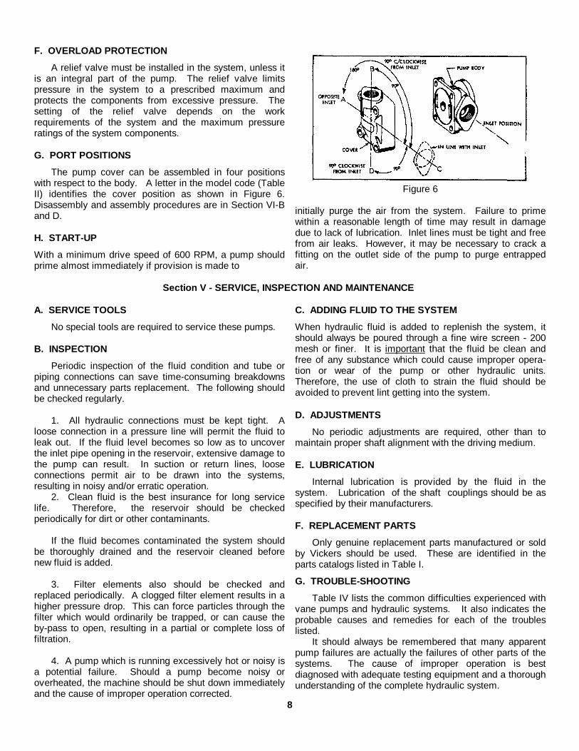
F. OVERLOAD PROTECTION
A relief valve must be installed in the system, unless itis an integral part of the pump. The relief valve limitspressure in the system to a prescribed maximum andprotects the components from excessive pressure. Thesetting of the relief valve depends on the workrequirements of the system and the maximum pressureratings of the system components.
G. PORT POSITIONS
The pump cover can be assembled in four positionswith respect to the body. A letter in the model code (TableII) identifies the cover position as shown in Figure 6.Disassembly and assembly procedures are in Section VI-Band D.
H. START-UP
With a minimum drive speed of 600 RPM, a pump shouldprime almost immediately if provision is made to
Figure 6
initially purge the air from the system. Failure to primewithin a reasonable length of time may result in damagedue to lack of lubrication. Inlet lines must be tight and freefrom air leaks. However, it may be necessary to crack afitting on the outlet side of the pump to purge entrappedair.
Section V - SERVICE, INSPECTION AND MAINTENANCE
A. SERVICE TOOLS
No special tools are required to service these pumps.
B. INSPECTION
Periodic inspection of the fluid condition and tube orpiping connections can save time-consuming breakdownsand unnecessary parts replacement. The following shouldbe checked regularly.
1. All hydraulic connections must be kept tight. Aloose connection in a pressure line will permit the fluid toleak out. If the fluid level becomes so low as to uncoverthe inlet pipe opening in the reservoir, extensive damage tothe pump can result. In suction or return lines, looseconnections permit air to be drawn into the systems,resulting in noisy and/or erratic operation.
2. Clean fluid is the best insurance for long servicelife. Therefore, the reservoir should be checkedperiodically for dirt or other contaminants.
If the fluid becomes contaminated the system shouldbe thoroughly drained and the reservoir cleaned beforenew fluid is added.
3. Filter elements also should be checked andreplaced periodically. A clogged filter element results in ahigher pressure drop. This can force particles through thefilter which would ordinarily be trapped, or can cause theby-pass to open, resulting in a partial or complete loss offiltration.
4. A pump which is running excessively hot or noisy isa potential failure. Should a pump become noisy oroverheated, the machine should be shut down immediatelyand the cause of improper operation corrected.
C. ADDING FLUID TO THE SYSTEM
When hydraulic fluid is added to replenish the system, itshould always be poured through a fine wire screen - 200mesh or finer. It is important that the fluid be clean andfree of any substance which could cause improper opera-tion or wear of the pump or other hydraulic units.Therefore, the use of cloth to strain the fluid should beavoided to prevent lint getting into the system.
D. ADJUSTMENTS
No periodic adjustments are required, other than tomaintain proper shaft alignment with the driving medium.
E. LUBRICATION
Internal lubrication is provided by the fluid in thesystem. Lubrication of the shaft couplings should be asspecified by their manufacturers.
F. REPLACEMENT PARTS
Only genuine replacement parts manufactured or soldby Vickers should be used. These are identified in theparts catalogs listed in Table I.
G. TROUBLE-SHOOTING
Table IV lists the common difficulties experienced withvane pumps and hydraulic systems. It also indicates theprobable causes and remedies for each of the troubleslisted.
It should always be remembered that many apparentpump failures are actually the failures of other parts of thesystems. The cause of improper operation is bestdiagnosed with adequate testing equipment and a thoroughunderstanding of the complete hydraulic system.
8

TABLE IV - TROUBLE SHOOTING CHARTTROUBLE PROBABLE CAUSE REMEDY
PUMP NOT DELIVERINGFLUID
DRIVEN IN THE WRONG DIRECTIONOF ROTATION
The drive direction must be changedimmediately to prevent seizure. Figure 9shows the correct ring position for eachdirection of rotation.
COUPLING OR SHAFT SHEARED ORDISENGAGED
Disassemble the pump and check the shaftand cartridge for damage. (See SectionVI.) Replace the necessary parts.
FLUID INTAKE PIPE IN RESERVOIRRESTRICTED
Check all strainers and filters for dirt andsludge. Clean if necessary.
FLUID VISCOSITY TOO HEAVY TO PICKUP PRIME
Completely drain the system. Add newfiltered fluid of the proper viscosity.
AIR LEAKS AT THE INTAKE PUMP NOTPRIMING
Check the inlet connections to determinewhere air is being drawn in. Tighten anyloose connections. See that the fluid in thereservoir is above the intake pipe opening.Check the minimum drive speed whichmay be too slow to prime the pump.
RELIEF VALVE STUCK OPEN (MODELSWITH INTEGRAL RELIEF VALVE ONLY).
Disassemble the pump and wash the valvein clean solvent. Return the valve to itsbore and check for any stickiness. Agritty feeling on the valve periphery can bepolished with crocus cloth. Do not removeexcess material, round off the edges of thelands or attempt to polish the bore. Washall parts and reassemble the pump.
VANE(S) STUCK IN THE ROTORSLOT(S)
Disassemble the pump. Check for dirt ormetal chips. Clean the parts thoroughlyand replace any damaged pieces. Ifnecessary flush the system and refill it withclean fluid.
INSUFFICIENT PRESSUREBUILD-UP
SYSTEM RELIEF VALVE SET TOO LOW Use a pressure gauge to correctly adjustthe relief valve.
WORN PARTS CAUSING INTERNALLEAKAGE OF PUMP DELIVERY -
Replace pump cartridge.
PUMP MAKING NOISE PUMP INTAKE PARTIALLY BLOCKED Service the intake strainers. Check thefluid condition and, if necessary, drain andflush the system. Refill with clean fluid.
AIR LEAKS AT THE INTAKE OR SHAFTSEAL. (OIL IN RESERVOIR WOULDPROBABLY BE FOAMY)
Check the inlet connections and seal todetermine where air is being drawn in.Tighten any loose connections andreplace the seal if necessary. See that thefluid in the reservoir is above the intakepipe opening.
PUMP DRIVE SPEED TOO SLOW ORTOO FAST
Operate the pump at the recommendedspeed.
COUPLING MISALIGNMENT Check if the shaft seal bearing or otherparts have been damaged. Replace anydamaged parts. Realign the coupledshafts.
9
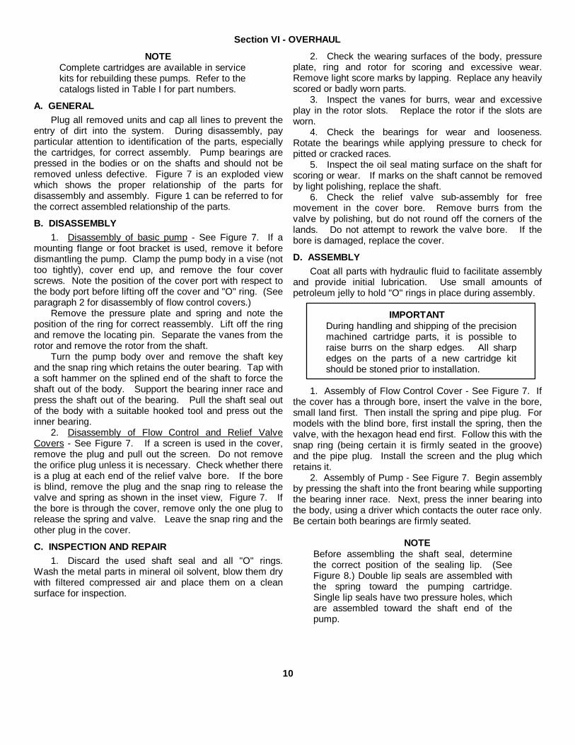
Section VI - OVERHAUL
NOTEComplete cartridges are available in servicekits for rebuilding these pumps. Refer to thecatalogs listed in Table I for part numbers.
A. GENERALPlug all removed units and cap all lines to prevent the
entry of dirt into the system. During disassembly, payparticular attention to identification of the parts, especiallythe cartridges, for correct assembly. Pump bearings arepressed in the bodies or on the shafts and should not beremoved unless defective. Figure 7 is an exploded viewwhich shows the proper relationship of the parts fordisassembly and assembly. Figure 1 can be referred to forthe correct assembled relationship of the parts.
B. DISASSEMBLY1. Disassembly of basic pump - See Figure 7. If a
mounting flange or foot bracket is used, remove it beforedismantling the pump. Clamp the pump body in a vise (nottoo tightly), cover end up, and remove the four coverscrews. Note the position of the cover port with respect tothe body port before lifting off the cover and "O" ring. (Seeparagraph 2 for disassembly of flow control covers.)
Remove the pressure plate and spring and note theposition of the ring for correct reassembly. Lift off the ringand remove the locating pin. Separate the vanes from therotor and remove the rotor from the shaft.
Turn the pump body over and remove the shaft keyand the snap ring which retains the outer bearing. Tap witha soft hammer on the splined end of the shaft to force theshaft out of the body. Support the bearing inner race andpress the shaft out of the bearing. Pull the shaft seal outof the body with a suitable hooked tool and press out theinner bearing.
2. Disassembly of Flow Control and Relief ValveCovers - See Figure 7. If a screen is used in the cover,remove the plug and pull out the screen. Do not removethe orifice plug unless it is necessary. Check whether thereis a plug at each end of the relief valve bore. If the boreis blind, remove the plug and the snap ring to release thevalve and spring as shown in the inset view, Figure 7. Ifthe bore is through the cover, remove only the one plug torelease the spring and valve. Leave the snap ring and theother plug in the cover.
C. INSPECTION AND REPAIR1. Discard the used shaft seal and all "O" rings.
Wash the metal parts in mineral oil solvent, blow them drywith filtered compressed air and place them on a cleansurface for inspection.
2. Check the wearing surfaces of the body, pressureplate, ring and rotor for scoring and excessive wear.Remove light score marks by lapping. Replace any heavilyscored or badly worn parts.
3. Inspect the vanes for burrs, wear and excessiveplay in the rotor slots. Replace the rotor if the slots areworn.
4. Check the bearings for wear and looseness.Rotate the bearings while applying pressure to check forpitted or cracked races.
5. Inspect the oil seal mating surface on the shaft forscoring or wear. If marks on the shaft cannot be removedby light polishing, replace the shaft.
6. Check the relief valve sub-assembly for freemovement in the cover bore. Remove burrs from thevalve by polishing, but do not round off the corners of thelands. Do not attempt to rework the valve bore. If thebore is damaged, replace the cover.
D. ASSEMBLYCoat all parts with hydraulic fluid to facilitate assembly
and provide initial lubrication. Use small amounts ofpetroleum jelly to hold "O" rings in place during assembly.
IMPORTANTDuring handling and shipping of the precisionmachined cartridge parts, it is possible toraise burrs on the sharp edges. All sharpedges on the parts of a new cartridge kitshould be stoned prior to installation.
1. Assembly of Flow Control Cover - See Figure 7. Ifthe cover has a through bore, insert the valve in the bore,small land first. Then install the spring and pipe plug. Formodels with the blind bore, first install the spring, then thevalve, with the hexagon head end first. Follow this with thesnap ring (being certain it is firmly seated in the groove)and the pipe plug. Install the screen and the plug whichretains it.
2. Assembly of Pump - See Figure 7. Begin assemblyby pressing the shaft into the front bearing while supportingthe bearing inner race. Next, press the inner bearing intothe body, using a driver which contacts the outer race only.Be certain both bearings are firmly seated.
NOTEBefore assembling the shaft seal, determinethe correct position of the sealing lip. (SeeFigure 8.) Double lip seals are assembled withthe spring toward the pumping cartridge.Single lip seals have two pressure holes, whichare assembled toward the shaft end of thepump.
10
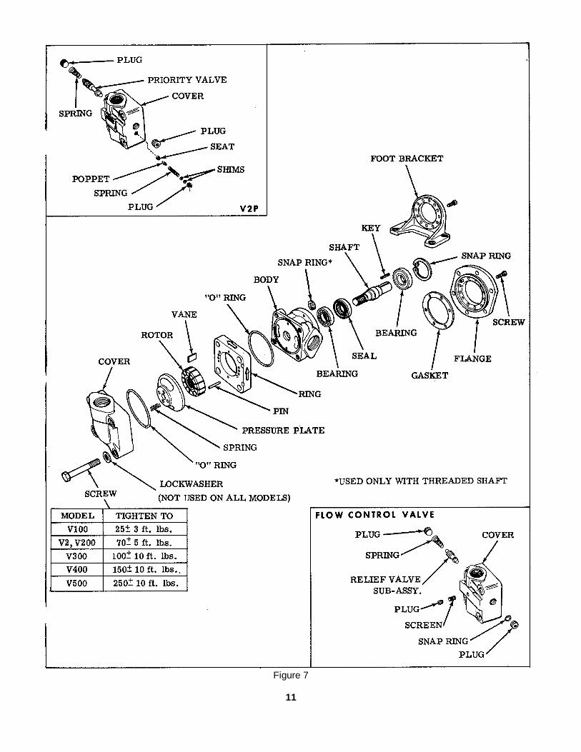
Figure 7
11
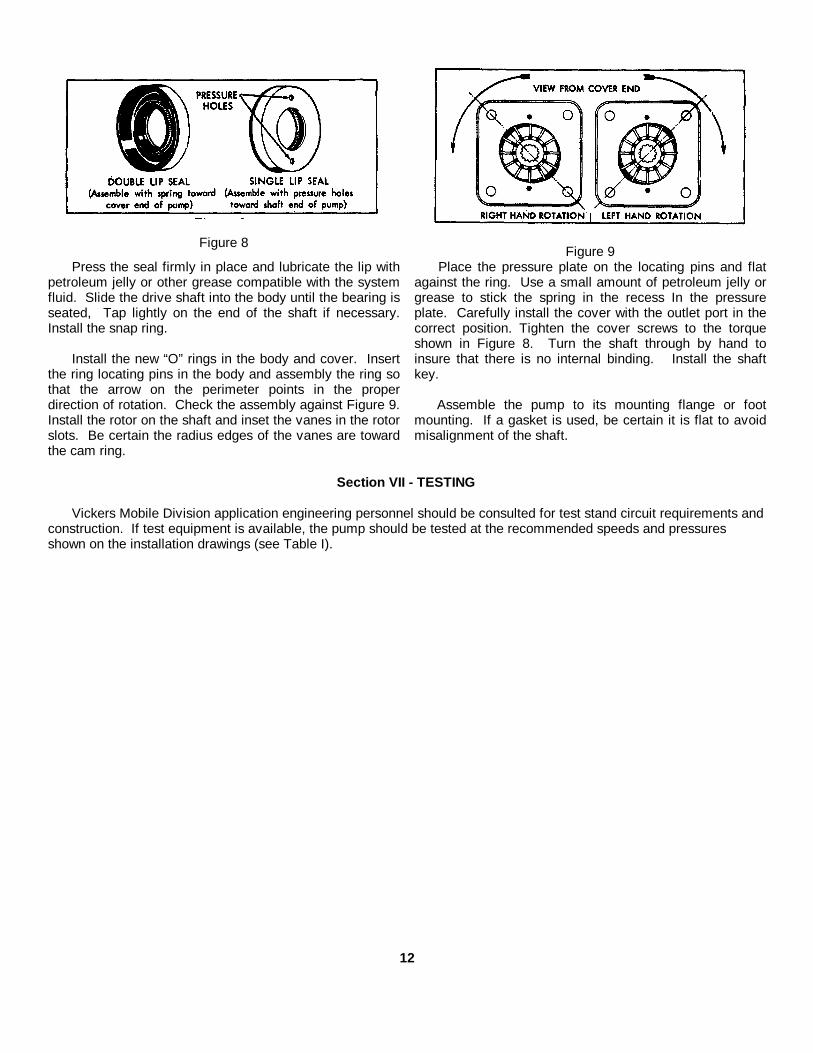
Figure 8Figure 9
Press the seal firmly in place and lubricate the lip withpetroleum jelly or other grease compatible with the systemfluid. Slide the drive shaft into the body until the bearing isseated, Tap lightly on the end of the shaft if necessary.Install the snap ring.
Install the new “O” rings in the body and cover. Insertthe ring locating pins in the body and assembly the ring sothat the arrow on the perimeter points in the properdirection of rotation. Check the assembly against Figure 9.Install the rotor on the shaft and inset the vanes in the rotorslots. Be certain the radius edges of the vanes are towardthe cam ring.
Place the pressure plate on the locating pins and flatagainst the ring. Use a small amount of petroleum jelly orgrease to stick the spring in the recess In the pressureplate. Carefully install the cover with the outlet port in thecorrect position. Tighten the cover screws to the torqueshown in Figure 8. Turn the shaft through by hand toinsure that there is no internal binding. Install the shaftkey.
Assemble the pump to its mounting flange or footmounting. If a gasket is used, be certain it is flat to avoidmisalignment of the shaft.
Section VII - TESTING
Vickers Mobile Division application engineering personnel should be consulted for test stand circuit requirements andconstruction. If test equipment is available, the pump should be tested at the recommended speeds and pressuresshown on the installation drawings (see Table I).
12
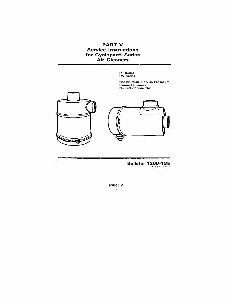
PART V1
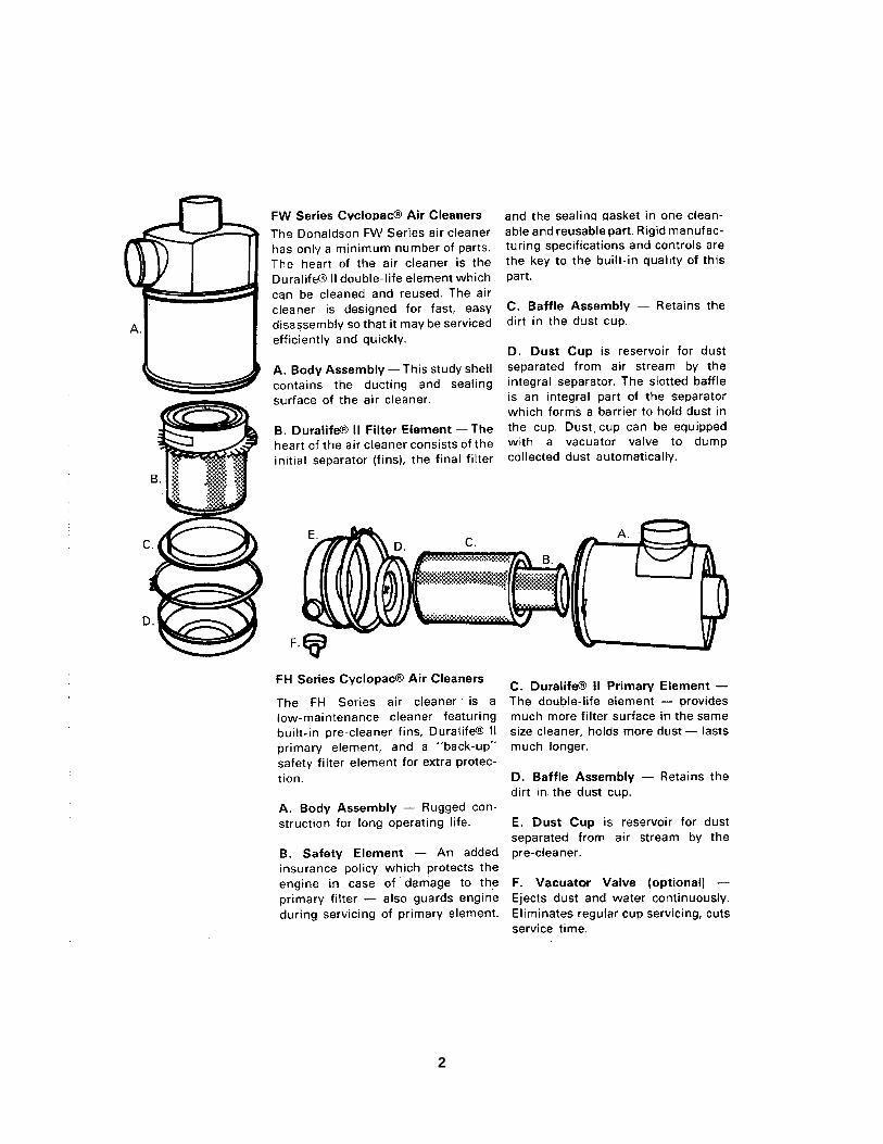
2
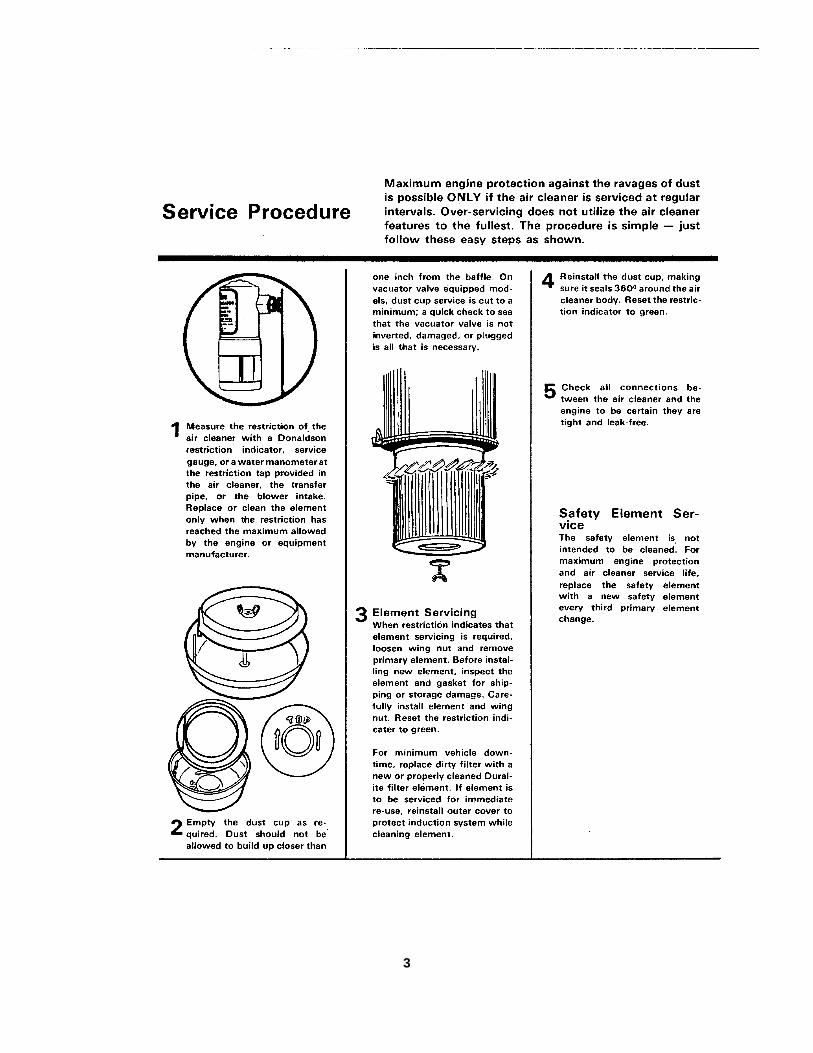
3

4

PART VI. PARTS LISTINGFOR
PAVING MACHINE, BITUMINOUS MATERIAL
CRAWLER MOUNTED
MODEL BSF-400
Serial Numbers 35627 thru 35633 inclusive
Contract No. DSA-700-77-C8481
Serial Numbers 36955 thru 36964 inclusive
Contract No. DAAE07-79-C5795
SECTION INDEX
DESCRIPTION SECTIONComponents Index ........................................................................................................... 1
Track ................................................................................................................................ 2
Main Frame .....................................................................................................................Hopper Wings ..................................................................................................................Tractor Accessories (Emblems and Attachments .............................................................Hoods, Covers and Walkways ........................................................................................ 3Acoustic Details - Hood, Covers and Walkways ...............................................................Operators Seat ................................................................................................................Operator Remote Control - Main Clutch and Forward - Reverse Shifter ...........................
Conveyors, Slat and Screw.............................................................................................. 4
Screed.............................................................................................................................. 5
Power Mounting and Drives ............................................................................................. 6Power Mounting PartsAir Cleaner and Exhaust SystemAlternator and DriveGenerator and DriveAutomatic Throttle ControlPower Take Off24 Speed Transmission, Clutch and Drive ShaftClutch, Transfer Case and BrakesStandard Conveyor Drive
Hydraulic ......................................................................................................................... 7
Electrical ......................................................................................................................... 8
}

SECTION 1
COMPONENTS

COMPONENTS
REF. NO. DESCRIPTION SECTION1 Track 22 Main Frame 33 Hopper Wings 34 Tractor Accessories 35 Hoods, Covers, and Walkways 36 Acoustic Details 37 Operators Seat 38 Slat Conveyor 49 Skirtboards and Covers - Slat Conveyor 410 Screw Conveyor 411 Remote Adjustable Screw Control 412 Screed 513 Screed Pull Arms 514 Oil Burner 515 Screed Lift 516 Power Mounting and Drive 617 Hydraulic Components 718 Base Electrical Parts 819 Screed Electrical Parts 8
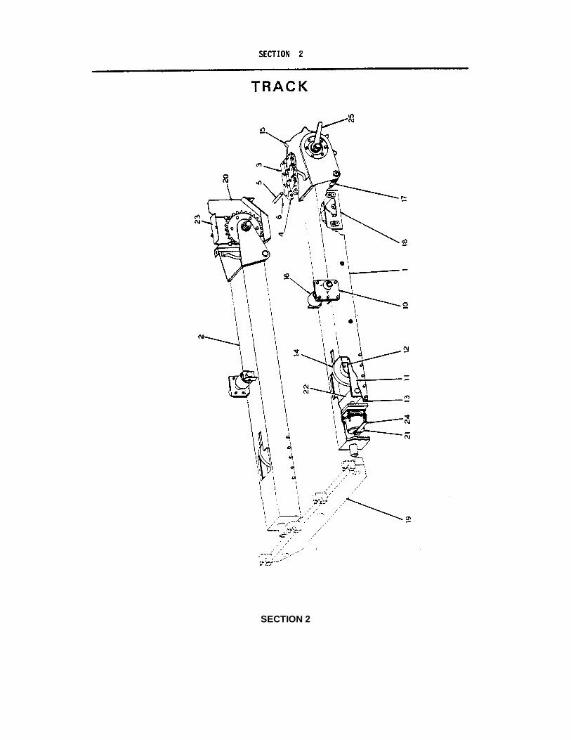
SECTION 2

TRACK
REF. NO. PART NUMBER DESCRIPTION QUANTITY1 5036BV03 Frame, Track - Left Hand 12 50368V02 Frame, Track - Right Hand 13 5036BD56 Track Link Assembly (27 Links) 2
5036BD56A Track Link Assembly (26 Links) 24 5036A43C Link, Track 1065 5036BD27 Pin 1066 7238-127 Pin, Roll 5/16" x 1-1/2" 21210 5036BD29 Trunnion 2
7010-045 Capscrew, 3/4" x 2-1/4" Hex Head NC 87012-030 Nut, 3/4" Hex NC 87014-009 Lockwasher, 3/4" 8
11 5036BP09 Bar, Side Yoke 412 7238-135 Pin, Roll 5/16" x 3-1/2" 413 5036BP10 Bar, Guide 4
7010-022 Capscrew, 1/2" x 1-1/2" Hex Head NC 167014-005 Lockwasher, 1/2" 16
14 See Take Up Idler - Section 2 215 See Rear Sprocket - Section 2 216 See Upper Roller - Section 2 217 See Lower Roller - Section 2 218 See Track Roller and Pivot Shaft - Section 2 619 Beam - See Main Frame - Section 120 5036BD49 Guard - Left Hand (Not Shown) 1
5036BD50 Guard - Right Hand (Shown) 17010-025 Capscrew, 1/2" x 2-1/4" Hex Head NC 27010-022 Capscrew, 1/2" x 1-1/2" Hex Head NC 445890-102-19 Locknut, ½ " NC 67014-020 Lockwasher, 1/2" 6
21 See Track Spring - Section 2 222 5036BD13 Anchor 223 5036BD51 Cover, Guard 2
7010-013 Capscrew, 3/8" x 1" Hex Head NC 27014-003 Lockwarsher. 3/8" 27014-018 Washer, 3/8" Flat 2
24 45500-750-05 Wrench, Track Adjusting 225 45500-750-02 Wrench, Track Frame (Not Shipped With Paver -
Available From Factory) 2
NOTE: Quantities Shown are for Both Tracks.

TRACK SPRING
REF. NO. PART NUMBER DESCRIPTION QUANTITY
1 5036BP06 Base 12 5036BP07 Spring, Outer 13 5036BP05 Cap 14 5036BP08 Spring, Inner 15 7017-029 Nut, 5/8" Jam NC 86 7008-342 Bolt, 1½ " x 17" NC 17 7017-036 Nut, 1½ " Jam NC 2
NOTE: Quantities are shown for one assembly only.

REAR SPROCKET
REF. NO. PART NUMBER DESCRIPTION QUANTITY
1 9704-050-01 Split Sprocket Assembly 12 5036BD53-02 Hub 13 5036BD54-01 Sprocket, Tooth Section 14 7455-013 Screw, Shoulder 3/4" x 1-1/2" 64A 7014-023 Washer, 3/4" 65 45890-102-17 Locknut, 5/8" NC 66 7258-013 Cone, Timken 27 7258-004 Cup, Timken 28 5036B059 Sprocket 19 5036BD06-02 Cap 110 7048-046 Shim, .020" 111 7048-047 Shim, .007" 112 7048-048 Shim, .005" 113 45200-040 Seal, Oil 214 50368D07 Plate 115 7049-003 Washer, Timken 216 7017-038 Nut, 1-3/4" Jam NC 417 7394-103 Capscrew, 5/8" x 2-1/4" Hex Head NF 618 7010-023 Capscrew, 1/2" x 1-3/4" Hex Head NC 1219 7017-051 Nut, 5/8" Jam Hex NF 620 7014-005 Lockwasher, 1/2" 1221 7024-001 Plug, '1/8" Pipe 222 5036B004 Shaft 123 See Track - Section 2
NOTE: Quantities listed are for one assembly only.
LITHO IN U.S.A

TAKE-UP IDLER
REF. NO. PART NUMBER DESCRIPTION QUANTITY
1 5036BD26-02 Idler, Track 12 9701-020 Shaft 13 7376-005 Cone, Timken 24 7376-001 Cup, Timken 2-5 50368D10-02 Cap 26 7048-014 Shim, .020" As Req.7 7048-015 Shim, .0071's As Req.8 7048-016 Shim, .005" As Req.9 45200-008 Seal, Oil 210 7010-021 Capscrew, 1/2" x 1-1/4" Hex Head NC 811 7014-005 Lockwasher, 1/2" 812 7024-001 Plug, 1/8" Pipe 2
NOTE: Quantities listed are for one assembly only.
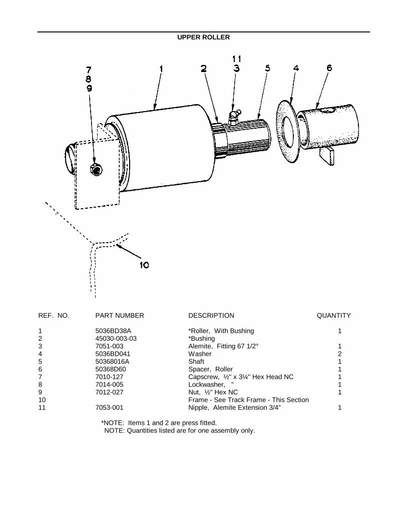
UPPER ROLLER
REF. NO. PART NUMBER DESCRIPTION QUANTITY
1 5036BD38A *Roller, With Bushing 12 45030-003-03 *Bushing3 7051-003 Alemite, Fitting 67 1/2° 14 5036BD041 Washer 25 50368016A Shaft 16 50368D60 Spacer, Roller 17 7010-127 Capscrew, ½ " x 3¼" Hex Head NC 18 7014-005 Lockwasher, " 19 7012-027 Nut, ½ " Hex NC 110 Frame - See Track Frame - This Section11 7053-001 Nipple, Alemite Extension 3/4" 1
*NOTE: Items 1 and 2 are press fitted.NOTE: Quantities listed are for one assembly only.
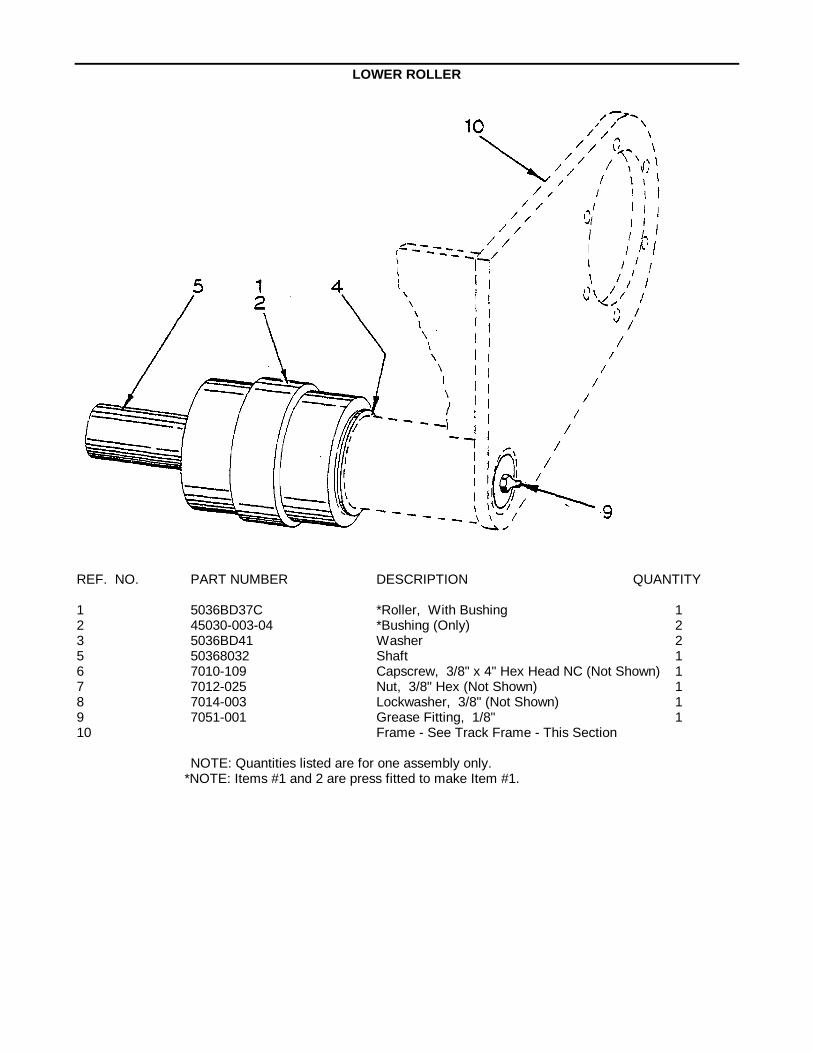
LOWER ROLLER
REF. NO. PART NUMBER DESCRIPTION QUANTITY
1 5036BD37C *Roller, With Bushing 12 45030-003-04 *Bushing (Only) 23 5036BD41 Washer 25 50368032 Shaft 16 7010-109 Capscrew, 3/8" x 4" Hex Head NC (Not Shown) 17 7012-025 Nut, 3/8" Hex (Not Shown) 18 7014-003 Lockwasher, 3/8" (Not Shown) 19 7051-001 Grease Fitting, 1/8" 110 Frame - See Track Frame - This Section
NOTE: Quantities listed are for one assembly only.*NOTE: Items #1 and 2 are press fitted to make Item #1.
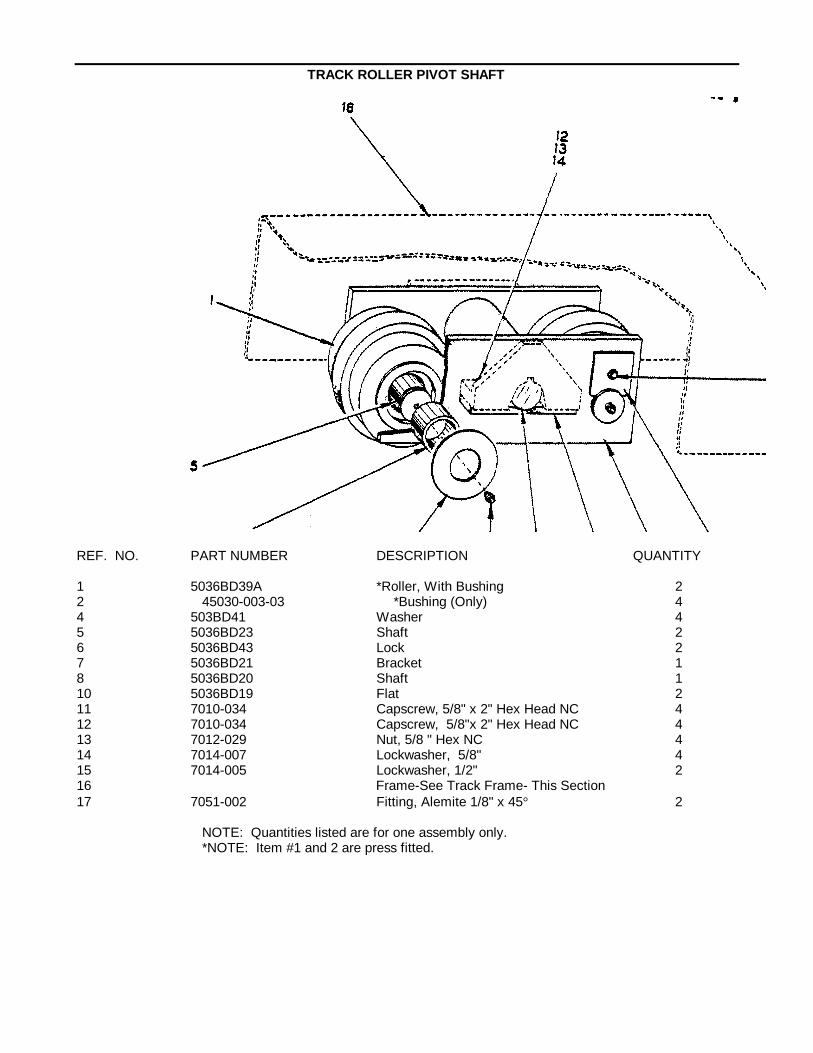
TRACK ROLLER PIVOT SHAFT
REF. NO. PART NUMBER DESCRIPTION QUANTITY
1 5036BD39A *Roller, With Bushing 22 45030-003-03 *Bushing (Only) 44 503BD41 Washer 45 5036BD23 Shaft 26 5036BD43 Lock 27 5036BD21 Bracket 18 5036BD20 Shaft 110 5036BD19 Flat 211 7010-034 Capscrew, 5/8" x 2" Hex Head NC 412 7010-034 Capscrew, 5/8"x 2" Hex Head NC 413 7012-029 Nut, 5/8 " Hex NC 414 7014-007 Lockwasher, 5/8" 415 7014-005 Lockwasher, 1/2" 216 Frame-See Track Frame- This Section17 7051-002 Fitting, Alemite 1/8" x 45° 2
NOTE: Quantities listed are for one assembly only.*NOTE: Item #1 and 2 are press fitted.
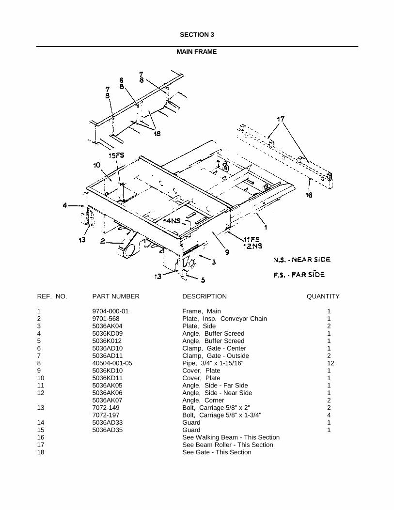
SECTION 3
MAIN FRAME
REF. NO. PART NUMBER DESCRIPTION QUANTITY
1 9704-000-01 Frame, Main 12 9701-568 Plate, Insp. Conveyor Chain 13 5036AK04 Plate, Side 24 5036KD09 Angle, Buffer Screed 15 5036K012 Angle, Buffer Screed 16 5036AD10 Clamp, Gate - Center 17 5036AD11 Clamp, Gate - Outside 28 40504-001-05 Pipe, 3/4" x 1-15/16" 129 5036KD10 Cover, Plate 110 5036KD11 Cover, Plate 111 5036AK05 Angle, Side - Far Side 112 5036AK06 Angle, Side - Near Side 1
5036AK07 Angle, Corner 213 7072-149 Bolt, Carriage 5/8" x 2" 2
7072-197 Bolt, Carriage 5/8" x 1-3/4" 414 5036AD33 Guard 115 5036AD35 Guard 116 See Walking Beam - This Section17 See Beam Roller - This Section18 See Gate - This Section
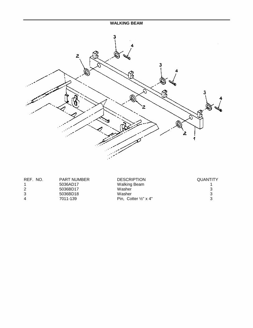
WALKING BEAM
REF. NO. PART NUMBER DESCRIPTION QUANTITY1 5036AD17 Walking Beam 12 5036BD17 Washer 33 5036BD18 Washer 34 7011-139 Pin, Cotter ½ " x 4" 3

BEAM ROLLER ASSEMBLY
REF. NO. PART NUMBER DESCRIPTION QUANTITY
1 5036AD32 Tube 12 41218-037-00 Shaft 13 7130-105 Setscrew, Socket Type 1/2" x 1-1/4 "-
NC - Cone Point 44 7017-027 Nut, Jam 1/2" - NC 45 7302-013 Bearing 2
NOTE: Quantities shown are for one Assembly only.
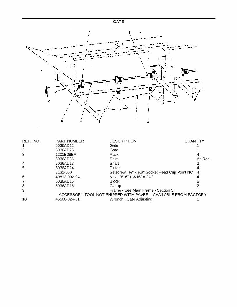
GATE
REF. NO. PART NUMBER DESCRIPTION QUANTITY1 5036AD12 Gate 12 5036AD25 Gate 13 1201B08BA Rack 4
5036AD36 Shim As Req.4 5036AD13 Shaft 25 5036AD14 Pinion 4
7131-050 Setscrew, ¼" x ½ a" Socket Head Cup Point NC 46 40812-002-04 Key, 3/16" x 3/16" x 2¼" 47 5036AD15 Block 68 5036AD16 Clamp 29 Frame - See Main Frame - Section 3
ACCESSORY TOOL NOT SHIPPED WITH PAVER. AVAILABLE FROM FACTORY.10 45500-024-01 Wrench, Gate Adjusting 1
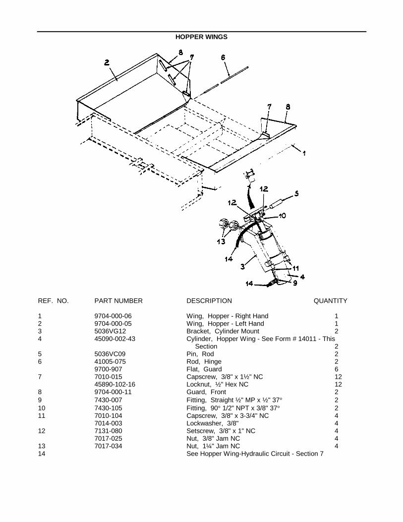
HOPPER WINGS
REF. NO. PART NUMBER DESCRIPTION QUANTITY
1 9704-000-06 Wing, Hopper - Right Hand 12 9704-000-05 Wing, Hopper - Left Hand 13 5036VG12 Bracket, Cylinder Mount 24 45090-002-43 Cylinder, Hopper Wing - See Form # 14011 - This
Section 25 5036VC09 Pin, Rod 26 41005-075 Rod, Hinge 2
9700-907 Flat, Guard 67 7010-015 Capscrew, 3/8" x 1½ " NC 12
45890-102-16 Locknut, ½ " Hex NC 128 9704-000-11 Guard, Front 29 7430-007 Fitting, Straight ½ " MP x ½ " 37° 210 7430-105 Fitting, 90° 1/2" NPT x 3/8" 37° 211 7010-104 Capscrew, 3/8" x 3-3/4" NC 4
7014-003 Lockwasher, 3/8" 412 7131-080 Setscrew, 3/8" x 1" NC 4
7017-025 Nut, 3/8" Jam NC 413 7017-034 Nut, 1¼" Jam NC 414 See Hopper Wing-Hydraulic Circuit - Section 7

CYLINDER-HOPPER WINGS
REF. NO. PART NUMBER DESCRIPTION QUANTITY
45090-002-43 Cylinder - Complete 11 45090-524-24 Piston2 45090-524-23 Piston 13 45090-524-22 Tube, 2nd Stage 14 45090-524-21 Tube, 1st Stage 15 45090-536-07 Case 16 45090-539-03 Head 17 45090-539-02 Head 18 45090-524-08 *Piston Ring 19 45090-524-07 *Piston Ring 110 45090-512-58 *O-Ring 111 45090-512-59 *O-Ring 112 45090-512-53 *O-Ring 113 45090-511-31 *Back Up Washer 114 45090-512-54 *O-Ring 115 45090-511-32 *Back Up Washer 116 45090-526-38 *U-Cup and Load O-Ring 117 45090-526-39 *U-Cup and Load O-Ring 118 45090-526-36 *Seal, Wiper 119 45090-526-37 *Seal, Wiper 1
*NOTE: These parts may be purchased as a repair kit by orderingPart Number 45090-526-35.
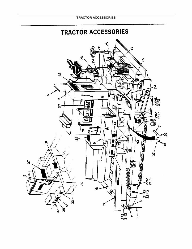
TRACTOR ACCESSORIES
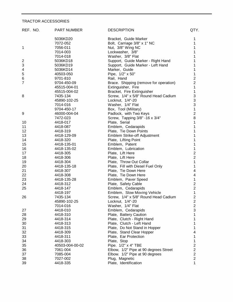
TRACTOR ACCESSORIES
REF. NO. PART NUMBER DESCRIPTION QTY.
5036KD20 Bracket, Guide Marker 17072-052 Bolt, Carriage 3/8" x 1" NC 1
1 7056-011 Nut, 3/8" Wing NC 17014-003 Lockwasher, 3/8" 17014-018 Washer, 3/8" Flat 1
2 5036KD18 Support, Guide Marker - Right Hand 13 5036KD19 Support, Guide Marker - Left Hand 14 5036KD14 Marker, Guide 15 40503-050 Pipe, 1/2" x 50" 16 9701-810 Rail, Hand 27 9704-450-09 Brace. Shipping (remove for operation) 2
45515-004-01 Extinguisher, Fire 145515-004-02 Bracket, Fire Extinguisher 1
8 7435-134 Screw, 1/4" x 5/8" Round Head Cadium 345890-102-25 Locknut, 1/4"-20 37014-016 Washer, 1/4" Flat 39704-450-17 Box, Tool (Military) 1
9 46000-004-04 Padlock, with Two Keys 27472-023 Screw, Tapping 3/8" -16 x 3/4" 8
10 4418-017 Plate, Serial 111 4418-087 Emblem, Cedarapids 112 4418-319 Plate, Tie Down Points 113 4418-129-09 Emblem Strike-off Adjustment 114 4418-320 Plate, Lifting Point 115 4418-135-01 Emblem, Patent 116 4418-135-02 Emblem, Lubrication 117 4418-305 Plate, Lift Here 218 4418-306 Plate, Lift Here 219 4418-304 Plate, Throw Out Collar 120 4418-135-18 Plate, Fill with Diesel Fuel Only 121 4418-307 Plate, Tie Down Here 422 4418-308 Plate, Tie Down Here 423 4418-135-28 Emblem, Paver Speed 124 4418-312 Plate, Safety Cable 225 4418-147 Emblem, Cedarapids 2
4418-197 Emblem, Slow Moving Vehicle 126 7435-134 Screw, 1/4" x 5/8" Round Head Cadium 2
45890-102-25 Locknut, 1/4"-20 27014-016 Washer, 1/4" Flat 2
27 4418-010 Emblem, Cedarapids 328 4418-310 Plate, Battery Caution 129 4418-314 Plate, Clutch - Right Hand 130 4418-313 Plate, Clutch - Left Hand 131 4418-315 Plate, Do Not Stand in Hopper 132 4418-309 Plate, Stand Clear Hopper 433 4418-311 Plate, Ear Protection 134 4418-303 Plate, Stop 135 40503-004-00-02 Pipe. 1/2" x 4" TBE 236 7061-004 Elbow, 1/2" Pipe at 90 degrees Street 237 7085-004 Elbow. 1/2" Pipe at 90 degrees 238 7027-002 Plug, Magnetic 239 4418-335 Plate, Identification 1

HOODS, COVERS AND WALKWAYS
REF. NO. PART NUMBER DESCRIPTION QUANTITY
1 9704-300-29 Shell, Radiator 12 9704-300-30 Hood, Rear 13 9704-300-31 Cover, Transmission 14 9704-300-32 Cover, Six Speed 15 9704-300-33 Hood, Center 16 9704-300-34 Panel, Side 27 9704-300-35 Cover, End 18 9704-300-36 Panel, Electric Box 19 45775-282-03 Boot, Shifter 310 46000-004-05 Lock, With Keys 111 46000-004-07 Hasplock, With Padlock & Keys 412 41733-003-01 Tape, Sponge 1" x 2" 0.713 9704-300-37 Brace, Transmission Cover 114 9704-300-72 Cover, Vandal 215 9704-300-73 Cover, Clutch 216 9704-300-75 Angle, Hood Support 217 5036KN03 Angle, Walkway Support 218 9704-300-76 Walkway, Floor Plate 419 45890-252-07 Bolt, 5/16" Washer Head NF 29

ACOUSTIC MATERIALHOODS, COVERS, WALKWAYS
REF. NO. PART NUMBER DESCRIPTION QUANTITY
1 9704-300-66 Acoustic Material, Side Panel 22 9704-300-67 Acoustic Material, Center Hood 13 9704-300-84 Acoustic Material, Walkway 44 9704-300-88 Acoustic Material, Hood 15 9704-300-89 Acoustic Material, Hood 16 9704-300-90 Acoustic Material, Hood End Cover 17 9704-301-76 Acoustic Material, Transmission Cover 18 9704-301-77 Acoustic Material, Transmission Cover 19 9704-301-78 Acoustic Material, Transmission Cover 110 9704-301-79 Acoustic Material, Transmission Cover 1

OPERATORS SEAT STANDARD
REF.NO. PART NO. DESCRIPTION QUANTITY
1 5036MD01 Seat Assembly 12 5036iNID01-01 Cushion, Seat 13 5036MD01-02 Cushion, Back Rest 14 5036MD02 Pedestal 1

SLAT CONVEYOR
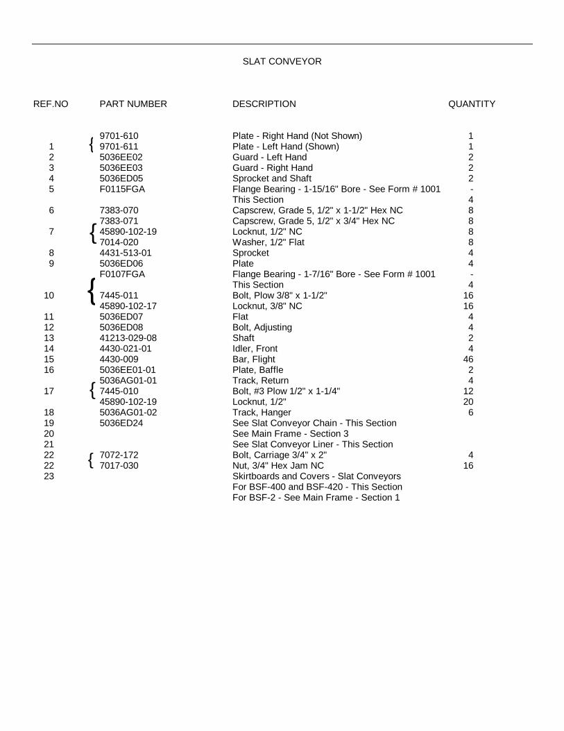
SLAT CONVEYOR
REF.NO PART NUMBER DESCRIPTION QUANTITY
9701-610 Plate - Right Hand (Not Shown) 11 9701-611 Plate - Left Hand (Shown) 12 5036EE02 Guard - Left Hand 23 5036EE03 Guard - Right Hand 24 5036ED05 Sprocket and Shaft 25 F0115FGA Flange Bearing - 1-15/16" Bore - See Form # 1001 -
This Section 46 7383-070 Capscrew, Grade 5, 1/2" x 1-1/2" Hex NC 8
7383-071 Capscrew, Grade 5, 1/2" x 3/4" Hex NC 87 45890-102-19 Locknut, 1/2" NC 8
7014-020 Washer, 1/2" Flat 88 4431-513-01 Sprocket 49 5036ED06 Plate 4
F0107FGA Flange Bearing - 1-7/16" Bore - See Form # 1001 -This Section 4
10 7445-011 Bolt, Plow 3/8" x 1-1/2" 1645890-102-17 Locknut, 3/8" NC 16
11 5036ED07 Flat 412 5036ED08 Bolt, Adjusting 413 41213-029-08 Shaft 214 4430-021-01 Idler, Front 415 4430-009 Bar, Flight 4616 5036EE01-01 Plate, Baffle 2
5036AG01-01 Track, Return 417 7445-010 Bolt, #3 Plow 1/2" x 1-1/4" 12
45890-102-19 Locknut, 1/2" 2018 5036AG01-02 Track, Hanger 619 5036ED24 See Slat Conveyor Chain - This Section20 See Main Frame - Section 321 See Slat Conveyor Liner - This Section22 7072-172 Bolt, Carriage 3/4" x 2" 422 7017-030 Nut, 3/4" Hex Jam NC 1623 Skirtboards and Covers - Slat Conveyors
For BSF-400 and BSF-420 - This SectionFor BSF-2 - See Main Frame - Section 1
{
{
{
{
{
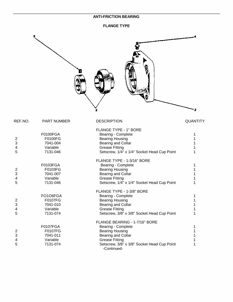
ANTI-FRICTION BEARING
FLANGE TYPE
REF.NO. PART NUMBER DESCRIPTION QUANTITY
FLANGE TYPE - 1" BOREF0100FGA Bearing - Complete 1
2 F0100FG Bearing Housing 13 7041-004 Bearing and Collar 14 Variable Grease Fitting 15 7131-046 Setscrew, 1/4" x 1/4" Socket Head Cup Point 1
FLANGE TYPE - 1-3/16" BOREF0103FGA Bearing - Complete 1
2 F0103FG Bearing Housing 13 7041-007 Bearing and Collar 14 Variable Grease Fitting 15 7131-046 Setscrew, 1/4" x 1/4" Socket Head Cup Point 1
FLANGE TYPE - 1-3/8" BOREFO1O6FGA Bearing - Complete 1
2 F0107FG Bearing Housing 13 7041-010 Bearing and Collar 14 Variable Grease Fitting 15 7131-074 Setscrew, 3/8" x 3/8" Socket Head Cup Point 1
FLANGE BEARING - 1-7/16" BOREF0107FGA Bearing - Complete 1
2 F0107FG Bearing Housing 13 7041-011 Bearing and Collar 14 Variable Grease Fitting 15 7131-074 Setscrew, 3/8" x 3/8" Socket Head Cup Point 1
-Continued-
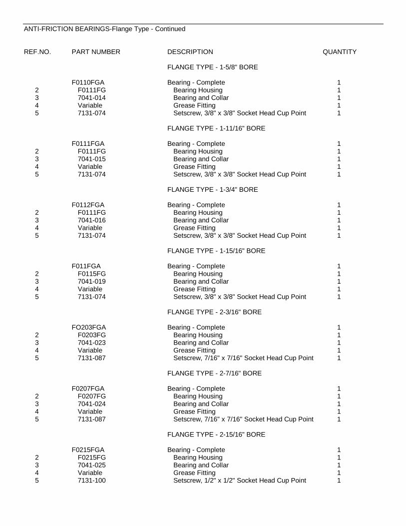
ANTI-FRICTION BEARINGS-Flange Type - Continued
REF.NO. PART NUMBER DESCRIPTION QUANTITY
FLANGE TYPE - 1-5/8" BORE
F0110FGA Bearing - Complete 12 F0111FG Bearing Housing 13 7041-014 Bearing and Collar 14 Variable Grease Fitting 15 7131-074 Setscrew, 3/8" x 3/8" Socket Head Cup Point 1
FLANGE TYPE - 1-11/16" BORE
F0111FGA Bearing - Complete 12 F0111FG Bearing Housing 13 7041-015 Bearing and Collar 14 Variable Grease Fitting 15 7131-074 Setscrew, 3/8" x 3/8" Socket Head Cup Point 1
FLANGE TYPE - 1-3/4" BORE
F0112FGA Bearing - Complete 12 F0111FG Bearing Housing 13 7041-016 Bearing and Collar 14 Variable Grease Fitting 15 7131-074 Setscrew, 3/8" x 3/8" Socket Head Cup Point 1
FLANGE TYPE - 1-15/16" BORE
F011FGA Bearing - Complete 12 F0115FG Bearing Housing 13 7041-019 Bearing and Collar 14 Variable Grease Fitting 15 7131-074 Setscrew, 3/8" x 3/8" Socket Head Cup Point 1
FLANGE TYPE - 2-3/16" BORE
FO203FGA Bearing - Complete 12 F0203FG Bearing Housing 13 7041-023 Bearing and Collar 14 Variable Grease Fitting 15 7131-087 Setscrew, 7/16" x 7/16" Socket Head Cup Point 1
FLANGE TYPE - 2-7/16" BORE
F0207FGA Bearing - Complete 12 F0207FG Bearing Housing 13 7041-024 Bearing and Collar 14 Variable Grease Fitting 15 7131-087 Setscrew, 7/16" x 7/16" Socket Head Cup Point 1
FLANGE TYPE - 2-15/16" BORE
F0215FGA Bearing - Complete 12 F0215FG Bearing Housing 13 7041-025 Bearing and Collar 14 Variable Grease Fitting 15 7131-100 Setscrew, 1/2" x 1/2" Socket Head Cup Point 1
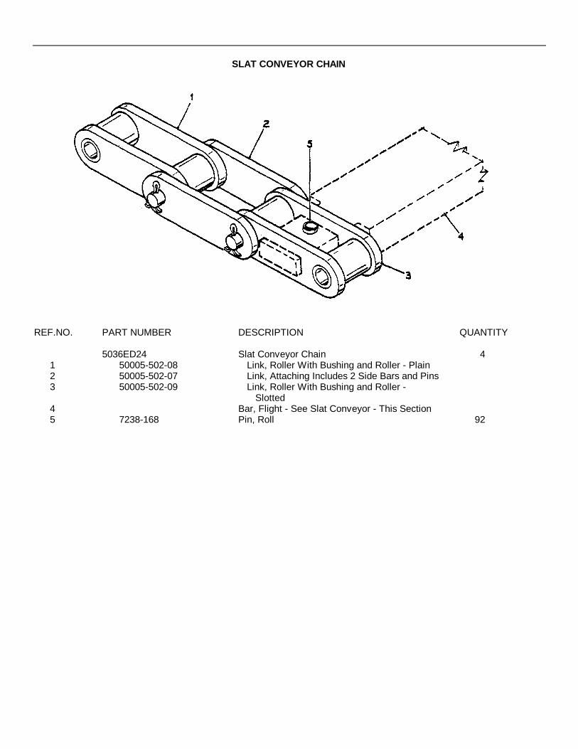
SLAT CONVEYOR CHAIN
REF.NO. PART NUMBER DESCRIPTION QUANTITY
5036ED24 Slat Conveyor Chain 41 50005-502-08 Link, Roller With Bushing and Roller - Plain2 50005-502-07 Link, Attaching Includes 2 Side Bars and Pins3 50005-502-09 Link, Roller With Bushing and Roller -
Slotted4 Bar, Flight - See Slat Conveyor - This Section5 7238-168 Pin, Roll 92
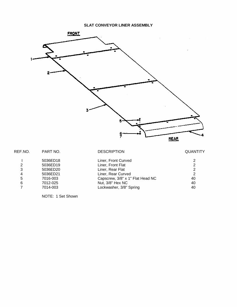
SLAT CONVEYOR LINER ASSEMBLY
REF.NO. PART NO. DESCRIPTION QUANTITY
I 5036ED18 Liner, Front Curved 22 5036ED19 Liner, Front Flat 23 5036ED20 Liner, Rear Flat 24 5036ED21 Liner, Rear Curved 25 7016-003 Capscrew, 3/8" x 1" Flat Head NC 406 7012-025 Nut, 3/8" Hex NC 407 7014-003 Lockwasher, 3/8" Spring 40
NOTE: 1 Set Shown

GREASE PIPING
SLAT CONVEYOR

GREASE PIPINGSLAT CONVEYOR
REF.NO. PART NUMBER DESCRIPTION QUANTITY
1 Run #1 - Slat Conveyor Front ShaftBearing Grease Piping
7061-001 Elbow, Street 1/8" x 90° 440500-001-08-01 Nipple, 1/8" x 1-1/2" 47085-001 Elbow, Pipe 1/8" x 90° 440500-007-0.8-01 Nipple, 1/8" x 7-1/2" 47084-001 Coupling, Pipe 1/8" 47051-002 Fitting, Grease 1/8" x 45° 445000-251-01 Clamp, Tube 47095-035 Bolt, Stove 1/4" x 1/2" NC 47014-001 Lockwasher, 1/4" 4
2 Run #2 - Slat Conveyor Rear ShaftOuter Bearing Grease Piping
7061-001 Elbow, Street 1/8" x 90° 240500-002-00-01 Nipple, 1/8" x 2" 27085-001 Elbow, Pipe 1/8" x 90° 240500-007-08-01 Nipple, 1/8" x 7-1/2" 27085-001 Elbow, Pipe 1/8" x 90° 240500-008-00-01 Nipple, 1/8" x 8" 27084-001 Coupling, Pipe 1/8" 27051-002 Fitting, Grease 1/8" x 45° 27000E23B Base, Tube Clamp 27095-035 Bolt, Stove 1/4" x 1/2" NC 27014-001 Lockwasher, 1/4" 245000-251-01 Tube, Clamp 2
3 Run #3 - Slat Conveyor Rear ShaftInner Bearing Grease Piping
7061-001 Elbow, Street 1/8" x 90° 240500-002-00-01 Nipple, 1/8" x 2" 27085-001 Elbow, Pipe 1/8" x 90° 240500-008-08-01 Nipple, 1/8" x 8-1/2" 27085-001 Elbow, Pipe 1/8" x 90° 240500-013-00-01 Nipple, 1/8" x 13" 27084-001 Coupling, Pipe 1/8" 27051-002 Fitting, Grease 1/8" x 45° 245000-251-01 Clamp, Tube 27000E23B Base, Tube Clamp 27095-035 Bolt, Stove 1/4" x 1/2" NC 27014-001 Lockwasher, 1/4" 2

SKIRTBOARD AND COVERS
SLAT CONVEYOR
REF.NO. PART NUMBER DESCRIPTION QUANTITY
1 5036AD09-01 Cover, Front 22 5036AK13 Skirtboard, Front 23 5036AD05 Skirtboard, Rear 44 5036AD07 Cover, Center 15 See Main Frame - Section 3

GREASE PIPING
SCREW CONVEYOR
REF.NO. PART NUMBER DESCRIPTION QUANTITY1
Grease Piping, Screw Conveyor Inner Bearing40500-004-00-01 Nipple, 1/8" x 4" 27061-001 Elbow, Pipe 1/8" x 90° 440500-008-00-01 Nipple, 1/8" x 8" 47084-001 Coupling, Pipe 1/8" 27051-003 Fitting, Grease 1/8" x 67° 245000-251-01 Clamp, Tube 27000E23B Base, Tube Clamp 27095-035 Bolt, Stove 1/4" x 1/2" NC 27014-001 Lockwasher, 1/4" 2

SCREW CONVEYOR14" DIAMETER
LEFT HAND SIDE SHOWN-RIGHT SIDE TYPICAL-

SCREW CONVEYOR14" DIAMETER - PARTS LIST NO .
REF.NO. PART NUMBER DESCRIPTION QUANTITY
1 5036DD21-01 *Flange - Left Hand (Shown) 15036DD22-01 *Flange - Right Hand (Opposite Side-Not Shown) 1
2 7010-020 Capscrew, 1/2" x 1" Hex Head NC 87014-005 Lockwasher, 1/2" 8
3 F011SFGA Flange Bearing - 1-15/16" Bore - See Form # 1001 4For BSF-2 Paver - See Section 12For Any Other Paver - See This Section
4 9700-608 Plate, Seal 45 5036BD41 Washer 46 7445-013 Bolt, Plow 1/2" x 1/2" 8
45890-102-19 Locknut, 1/2" 87 5036FD03 Sprocket, With Shaft 28 5036FJO2 *Screw - Left Hand (Shown) 1
5036FJ03 *Screw - Right Hand (Opposite Side-Not Shown) 17383-109 Capscrew, Grade 5, 5/8" x 3-3/4" Hex NC 4
9 7014-007 Lockwasher, 5/8" 47012-029 Nut, 5/8" Hex NC 4
10 5036FJ04 *Screw - Left Hand (Shown) 15036FJ05 *Screw - Right Hand (Opposite Side-Not Shown) 1
*Hanger, Bearing - Left Hand (Shown) 111 *Hanger, Bearing - Right Hand (Opposite Side-
Not Shown) 112 47445-003 Bolt, Plow 1/2" x 2p." 8
45890-102-19 Locknut, 1/2" 813 5036FD14 Shaft 214 5036FD22 Agitator 2
40500-015-00-01 Pipe, 1/8" x 15" 215 7084-001 Coupling 2
7051-002 Fitting, Grease 1/8" x 45° 217 See Remote Adjustable Screw Control - This
Section19 See Grease Piping - This Section21 7051-001 Fitting, Grease 1/8" 222 9701-735 Cover, Screw 2
*NOTE: Right and Left Hand is determined by facing direction of paver travel.
{{
{
{
{{
{
{
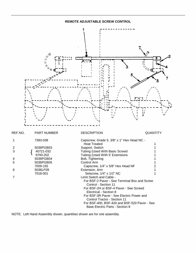
REMOTE ADJUSTABLE SCREW CONTROL
REF.NO. PART NUMBER DESCRIPTION QUANTITY
1 7383-038 Capscrew, Grade 5, 3/8" x 1" Hex Head NC -Heat Treated 1
2 5036PGB03 Support, Switch 13 40721-032 Tubing (Used With Basic Screed 1
9700-202 Tubing (Used With 5' Extensions 14 5036PGB04 Bolt, Tightening 15 5036PGB05 Control Arm 1
7009-155 Capscrew, 1/4" x 5/8" Hex Head NF 26 5036LF09 Extension, Arm 1
7018-001 Setscrew, 1/4" x 1/2" NC 17 Limit Switch and Cable -
For BSF-2 Paver - See Terminal Box and ScrewControl - Section 11
For BSF-2H or BSF-4 Paver - See ScreedElectrical - Section 8
For BSF-3R Paver - See Electric Power andControl Tractor - Section 11
For BSF-400, BSF-420 and BSF-520 Paver - SeeBase Electric Parts - Section 8
NOTE: Left Hand Assembly shown, quantities shown are for one assembly.
{
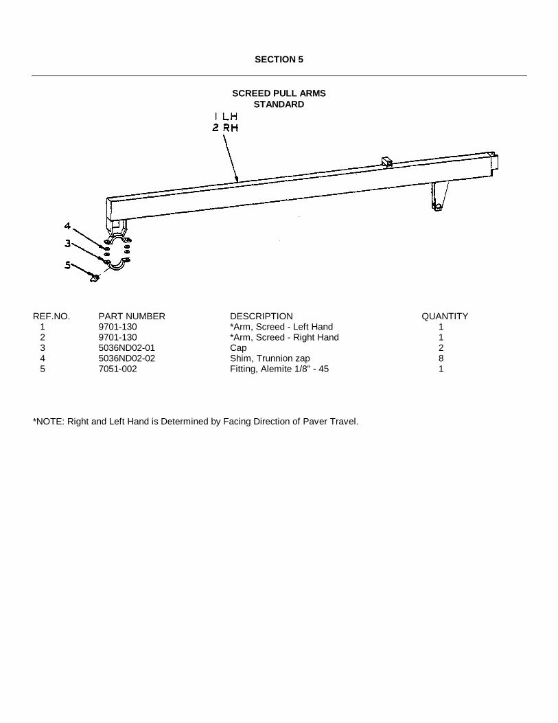
SECTION 5
SCREED PULL ARMSSTANDARD
REF.NO. PART NUMBER DESCRIPTION QUANTITY1 9701-130 *Arm, Screed - Left Hand 12 9701-130 *Arm, Screed - Right Hand 13 5036ND02-01 Cap 24 5036ND02-02 Shim, Trunnion zap 85 7051-002 Fitting, Alemite 1/8" - 45 1
*NOTE: Right and Left Hand is Determined by Facing Direction of Paver Travel.
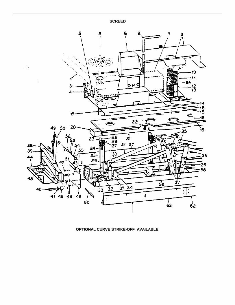
SCREED
OPTIONAL CURVE STRIKE-OFF AVAILABLE

SCREED
REF.NO. PART NUMBER DESCRIPTION QUANTITY1 See Screed Pull Arms - This Section2 See Screed Adjusting Mechanism - This Section
9701-699 Moldboard, Models BSF-2, BSF-3R, BSF-400 andBSF-420 1
9701-700 Moldboard, Models BSF-2H, BSF-4 and BSF-520 13 7012-027 Nut, 1/2" Hex NC 20
5036NH21 Washer 207472-026 Screw, 3/8" x 1¼" Swage Form 147012-025 Nut, 3/8" NC 14
4 5036NH07 Bolt, 1½ " x 6" Hex Head NC 25 7017-036 Nut, 1½ " 46 9701-192 *Stair - Right Hand (Not Shown) 1
9701-193 *Stair - Left Hand (Shown) 17 See Screed Vibrator
BSF-2 and BSF-3R - Section 11BSF-2H, BSF-4, BSF-520, BSF-420 and BSF-400 -Section 8
8 See Burner Oil Lines - This Section8A 9700-559 Liner, Burner Stack With Insulation 19 9701-199 Hand Rail 110 45335-500-07 Clamp 211 5036NK02-01 Guard 112 5036NH12 Gauge, Crown 213 5036NH49 Back Plate, Gauge Crown 214 9701-249 Frame, Screed 115 5036NJ04 Seal 416 5036NH38 Plate, Mounting 417 5036N025 Walkway 1
5021DE01 Key, Stud 418 41700-114-24 Insulation 119 5036NU03 Panel, Inner 120 5036ND22 Plate, End 221 5036ND21 Duct, Heat 122 5036ND23 Clip 823 5036RUB15 Gauge, Strike-Off Height 4
5036RUF04 Bar and Bolt Adjusting 424 7383-070 Capscrew, Grade 5, ½ " x 1½ " Hex Head NC 4
7014-005 Lockwasher, ½ " 425 5036NU13 Support, Strike-Off Adjust 826 5036NU06 Pointer, Strike-Off Gauge 427 7012-029 Nut, 5/8" Hex NC 828 5036RUB06 Bracket, Adjusting 429 5036NH46 Bolt, 3/4" x 2¼" Hardened 162 4 45890-103-02 Locknut, 3/4" Hex NC 1630 7012-034 Nut, 1¼" Hex NC 431 9701-509 Arm, Crown Adjusting 432 7010-023 Capscrew, Grade 5, ½ " x 1" Hex Head NC 833 9700-404 *Frame, Screed - Right Hand (Not Shown) 1
9704-405 *Frame, Screed - Left Hand (Shown) 134 5036NH04 Link, Outside 835 See Crown Adjusting Mechanism - This Section
-Continued-
{{
{
{
{
{

SCREED - Continued
REF.NO. PART NUMBER DESCRIPTION QUANTITY
36 5036NH05 Link, Center 837 5036NH06 Bolt, 3/4" x 2-3/4" Hex Head NC 8
7017-030 Nut, 3/4" Jam 1638 9701-042 *Plate, Side - Right Hand (Not Shown) 1
9701-043 *Plate, Side - Left Hand (Shown) 139 9701-044 *Arm, Support - Right Hand (Not Shown) 1
9701-045 *Arm, Support - Left Hand (Shown) 140 7010-157 **Capscrew, 1" x 3k" Hex Head NC 241 7014-025 **Washer, 1" Flat 242 9700-199 **Spacer 243 7012-032 **Nut, I" Hex NC 4
5036RD06B *Shoe, Cut-Off 12" (Not Shown) 144 5036RD07B *Shoe, Cut-Off 24" (Shown) 1
7010-021 Capscrew, ½ " x 1i" Hex Head NC 245 7014-020 Washer, ½ " Flat 2
7014-005 Lockwasher, ½ " 27012-027 Nut, ½ " Hex NC 2
46 9700-197 *Plate, End - Right Hand (Not Shown) 19700-195 *Plate, End - Left Hand (Shown) 1
47 7389-056 Capscrew, Grade 5, 5/8" x 2" Flat Head 47010-035 Capscrew, 5/8" x 2¼" Hex 'Head NC 4
48 7014-007 Lockwasher, 5/8" 449 5036NB03 Anchor, Chain Adjustment 2
7014-023 Washer, 3/4" Flat 250 5036NB04 **Handle 251 9704-900-11 **Handle 252 7455-002 Screw, Shoulder 653 7453-601 Washer, 5/8" Compression Type 1254 5036NU05 Washer 655 5036RUB07 Seal 656 5036RUF02 *Strike-Off Flat 60" 157 5036RUF03 *Strike-Off Flat 60" 158. 5036NH02-07 Indicator, Crown 259 9701-063 Screed, Bottom 160 45500-036-06 Gauge, Strike-Off 161 45500-020-06 Wrench, 5/16" Allen 1
OPTIONAL'CURVED STRIKE-OFFS AVAILABLE62 5036RUG02 *Strike-Off, Curved - Right Hand63 5036RUG03 *Strike-Off, Curved - Left Hand
*NOTE: Right and Left Hand is determined by direction of paver travel.
**NOTE: Items 40, 41, 42, 43, 50 and 51 are included by Ordering HardwarePackage, Part Number 9701-369.

DUAL CROWN ADJUSTING MECHANISM
REF. NO. PART NUMBER DESCRIPTION QUANTITY1 5036QL02 Turnbuckle, Front 12 9700-179 Turnbuckle, Rear 13 5036QL04 Drawbolt - Right Hand Thread - Front 14 9700-429 Drawbolt - Right Hand Thread - Rear 15 5036QLO5 Drawbolt - Left Hand Thread' 26 5036NH06 Bolt, 3/4" x 2-3/4" 47 45890-103-02 Locknut, 3/4" Jam NC 88 9700-161 Chain Package 1
50005-020 Chain, Roller 5.1'50005-020-01 Link, Offset Coupler 150005-020-03 Link, Connecting 1
9 5036QL14 Spreader 110 See Screed - This Section11 5036QL13 Angle, Clip 212 9700-181 Sprocket 113 9700-180 Collar, Adjusting 114 7253-050 Ring, Retaining 1
7010-021 Capscrew, 1/2" x 1-1/4" Hex NC 215 7014-005 Lockwasher, 1/2" 2
7012-027 Nut, 1/2" Hex NC 216 9700-109 Lock 117 9700-183 Gauge 118 45500-750-06 Wrench 1
{

SCREED ADJUSTING MECHANISM

SCREED ADJUSTING MECHANISM
REF.NO PART NUMBER DESCRIPTION QUANTITY1 5036ND31 Handwheel 2
7131-052 Setscrew, ¼" x 3/4" Socket Head Cup Point 22 40800-002 Key, ¼" Square x 2" 23 9704-550-41 Screw, Screed Adjusting 24 5036ND54-01 Indicator 25 7018-022 Setscrew, 3/8" x 5/8" Square Head 26 9700-395 Scale 27 5036ND18 Shim, 1/16" As Req.8 5036ND51 Shim, 1/32" As Req.9 5036ND30 Cap 2
10 5036ND32-01 Nut 211 5036ND56 Bracket 212 5036ND33-01 Lock 213 5036ND19 Lever, Step Latch 214 5036NH13 Spring, Compression 215 4431-550-02 Bearing - Complete 215A 4431-550-01 Bearing 215B 7041-026 Ball Bearing 215C 7051-001 Grease Fitting, 1/8" 216 7253-040 Ring, Snap 217 5036NH26 Gasket, Bottom 218 7383-230 Lockscrew, Grade 5, 5/8" x 1;" NC 219 7014-022 Washer, 5/8" Flat 420 7383-080 Capscrew, Grade 5, ½ " x 4" NC 421 7383-076 Capscrew, Grade 5, ½ " x 3" NC 422 45890-102-19 Locknut, ½ " NC 8
{

BURNER AND OIL LINE
REF. NO. PART NUMBER DESCRIPTION QUANTITY9704-500-63 Spray Hose - Complete 1
1 45251-006-05 Extension 12 45251-001-76 Valve, Shut-Off 13 50030-001-21 Hose, 3/8" ID As Req.4 45191-004-05 Clamp, 3/8" Hose 25 40500-002-08-02 Nipple, Half 1/8" x 2 1/2" 16 45251-006-07 O-Ring 17 45251-006-06 O-Ring 18 45251-006-03 Nozzle, Cap 19 5036ND26A Tank, Fuel 110 45186-002-03 Strainer, Fuel 111 50030-001-21 Hose, 3/8" ID x 22" 212 7431-003 Connector, 3/8" Hose x ¼" NPT 213 7061-002 Elbow, ¼," 900 St. 214 7107-002 Bushing, 3/8" x i" Pipe Reducer 115 7431-008 Connector, 3/8" Hose x 3/8" - 370 216 7430-004 Fitting, ¼" MP x 3/8" - 370 St. 217 7304-001 Reducer, 1/4" x 1/8" NPT 118 40500-000-12-01 Nipple, 1/8" NPT 1
5036ND62 Bracket, Tank Mounting 219 7435-139 Screw, Machine ¼" x 1¼" NC 2
7014-016 Washer, ½ " Flat 27012-023 Nut, ¼" Hex NC 2
20 9704-550-61 Walkway 121 See Screed Oil Burner - This Section

SCREED OIL BURNER

SCREED OIL BURNER
REF.NO PART NUMBER DESCRIPTION QUANTITY
9704-550-62 Screed Oil Burner - Complete1 9700-881 Cover 12 7010-077 Capscrew, ¼"-20 x ½ " 4
7007-064 Washer, ¼" 43 45652-507-02 Housing 14 9704-550-25 Manifold 1
45652-508-02 Band, Shutter 15 7435-139 Screw, ¼" x ¼" Round Head 1
7439-006 Lockwasher, ¼" 17440-012 Nut, ¼"-20 1
6 45652-529-01 Wheel, Blower 17 4431-451-01 Standoff, Motor 18 7010-006 Capscrew, 5/16" x 3/4" 28 7014-002 Lockwasher, 5/16" 29 46098-400-09 Motor 1
10 47436-098 Screw, #10-32 x 3/4" 47439-003 Lockwasher, #10 4
11 45652-511-06 Coupling 112 45652-528-01-01 Pump, Fuel Unit 113 7010-013 Capscrew,. 3/8" x 1" 2
7014-003 Lockwasher, 3/8" 214 45252-003-02 Valve, Solenoid 215 40500-002-00-01 Nipple, 1/8" NPT x 2" 116 45652-518-02 Valve, Shut Off 117 40500-001-08-01 Nipple, 1/8" NPT x 1½ " 118 45652-518-01 Valve, Shut Off 900 119 45652-516-03 Line, Fuel Oil 120 9704-550-48 Electrode Oil Pipe - See Form # 14390 -
This Section 17435-135 Screw, ¼" x 3/4" Round Head 2
21 7439-006 Lockwasher, ¼" 27014-016 Washer, ¼" Flat 2
22 9704-600-60 Coil Switch - Complete 123 9704-550-28 Bracket 124 46176-006-01 Coil, Ignition 125 46200-009-03 Switch 126 9704-550-43 Name Tag 127 9704-500-29 Insulator 128 9704-600-58 Cable to Pulsator 129 45345-001-05 Spirap 1.3'30 9704-600-59 Wire, Coil to Switch 131 Liner, With Insulations - See Screed - This
Section
{
{
{
{

ELECTRODE AND OIL PIPE
REF.NO PART NUMBER DESCRIPTION QUANTITY
9704-550-48 Electrode and Oil Pipe - Complete1 45652-533-12 Bracket 12 45652-505-27 Rod, Negative Electrode 13 45652-505-24 Electrode 1
7435-098 Screw, #10-24 x 3/4" Round Head NC - Cadium4 Plated 1
7439-003 Lockwasher, #10 - Cadium Plated 15 9704-600-05 Wire, Ignition 16 9700-504 Pipe, Oil 17 9700-571 Nut, Fixture 28 7014-018 Washer, 3/8" Flat 29 45652-513-02 Cone, Air 1
10 45652-512-05 Adapter, Nozzle 111 45652-512-15 Nozzle, Tip 1.35 GPH @ 70° 1
7131-039 Setscrew, -10-24 x 1/2" 112 7439-003 Lockwasher, #10 - Cadium Plated 1
7440-009 Nut, #10-24 NC - Cadium Plated 113 7131-035 Setscrew, #10-24 x 1/4" 1
{
{
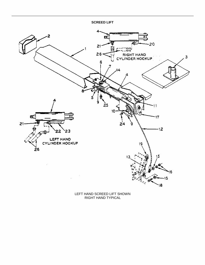
SCREED LIFT
LEFT HAND SCREED LIFT SHOWNRIGHT HAND TYPICAL

SCREED LIFT
REF.NO. PART NUMBER DESCRIPTION QUANTITY
1 5036CL03 Housing, Screed Lift 22 9701-145 Baffle, Screed Lift Housing 23 9704-450-03 Support, Operator Seat 24 45090-002-32 Cylinder - See Form # 11023 - This Section 25 5032-176-03 Shroud 26 5032-176-04 Support, Sheave 27 5032-176-05 Pin 28 40510-000-12 Spacer, 12" XH Pipe x 3/4" 49 5036CD04-01 Sheave 4
10 5036CD12 Shaft, Sheave 211 5036CD21 Shaft, Cable Anchor 212 9704-100-03 Cable, Screed Lift 213 9704-100-04 Cable, Safety 214 7014-028 Washer, 1-3/8"' Flat 215 7014-023 Washer, 3/4" Flat 416 7017-030 Nut, 3/4" Jam NC 417 5036CF07 Screed, Hook 218 7010-047 Capscrew, 3/4" x 2-3/4" NC 219 7262-009 Shackle 220 7430-006 Fitting, Straight 3/8" MP x ½ " 37° 121 7430-007 Fitting, Straight ½ " MP x ½ " 37° 222 7430-013 Fitting, Straight 3/8" FP x ½ " 37° 123 40539-005-08-01 Nipple, 3/8" XH Pipe x 5½ " 124 7051-001 Fitting, Grease 225 7051-003 Fitting, Grease 226 See Auxiliary Hydraulic Circuit - Section 727 See Screed Lift Hydraulic Circuit - Section 7
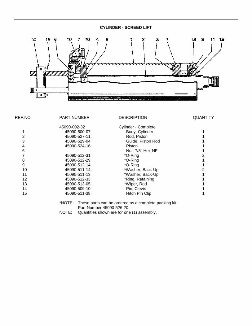
CYLINDER - SCREED LIFT
REF.NO. PART NUMBER DESCRIPTION QUANTITY
45090-002-32 Cylinder - Complete1 45090-500-07 Body, Cylinder 12 45090-527-11 Rod, Piston 13 45090-529-04 Guide, Piston Rod 14 45090-524-16 Piston 16 Nut, 7/8" Hex NF 17 45090-512-31 *O-Ring 28 45090-512-29 *O-Ring 19 45090-512-14 *O-Ring 110 45090-511-14 *Washer, Back-Up 211 45090-511-13 *Washer, Back-Up 112 45090-512-33 *Ring, Retaining 113 45090-513-05 *Wiper, Rod 114 45090-509-10 Pin, Clevis 115 45090-511-38 Hitch Pin Clip 1
*NOTE: These parts can be ordered as a complete packing kit,Part Number 45090-526-20.
NOTE: Quantities shown are for one (1) assembly.

12" SCREED EXTENSIONWITH ADJUSTABLE STRIKE - OFFS
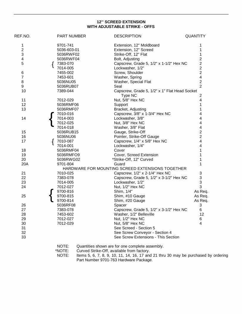
12’’ SCREED EXTENSIONWITH ADJUSTABLE STRIKE - OFFS
REF.NO. PART NUMBER DESCRIPTION QUANTITY
1 9701-741 Extension, 12" Moldboard 12 5036-603-01 Extension, 12" Screed 13 5036RWF02 Strike-Off, 12" Flat 14 5036RWF04 Bolt, Adjusting 25 7383-070 Capscrew, Grade 5, 1/2" x 1-1/2" Hex NC 2
7014-005 Lockwasher, 1/2" 26 7455-002 Screw, Shoulder 27 7453-601 Washer, Spring 48 5036NU05 Washer, Special Flat 29 5036RUB07 Seal 210 7389-044 Capscrew, Grade 5, 1/2" x 1" Flat Head Socket
Type NC 211 7012-029 Nut, 5/8" Hex NC 412 5036RMF06 Support 113 5036RMF07 Bracket, Adjusting 1
7010-016 Capscrew, 3/8" x 1-3/4" Hex NC 414 7014-003 Lockwasher, 3/8" 4
7012-025 Nut, 3/8" Hex NC 47014-018 Washer, 3/8" Flat 4
15 5036RUB15 Gauge, Strike-Off 216 5036NU06 Pointer, Strike-Off Gauge 217 7010-087 Capscrew, 1/4" x 5/8" Hex NC 4
7014-001 Lockwasher, 1/4" 418 5036RMF04 Cover 119 5036RMFO9 Cover, Screed Extension 120 5036RWG02 *Strike-Off, 12" Curved 120A 9701-804 Guard 1
HARDWARE FOR MOUNTING SCREED EXTENSIONS TOGETHER21 7010-025 Capscrew, 1/2" x 2-1/4" Hex NC 322 7383-078 Capscrew, Grade 5, 1/2" x 3-1/2" Hex NC 323 7014-005 Lockwasher, 1/2" 324 7012-027 Nut, 1/2" Hex NC 3
9700-816 Shim, 1/4" As Req.25 9700-815 Shim, #10 Gauge As Req.
9700-814 Shim, #20 Gauge As Req.26 5036RF08 Spacer 327 7383-078 Capscrew, Grade 5, 1/2" x 3-1/2" Hex NC 628 7453-602 Washer, 1/2" Belleville 1229 7012-027 Nut, 1/2" Hex NC 630 7012-029 Nut, 5/8" Hex NC 431 See Screed - Section 532 See Screw Conveyor - Section 433 See Screw Extensions - This Section
NOTE: Quantities shown are for one complete assembly.*NOTE: Curved Strike-Off, available from factory.NOTE: Items 5, 6, 7, 8, 9, 10, 11, 14, 16, 17 and 21 thru 30 may be purchased by ordering
Part Number 9701-763 Hardware Package.
{
{{
{

SCREW EXTENSIONS
LEFT HAND SIDE SHOWN-RIGHT SIDE TYPICAL-
REF.NO. PART NUMBER DESCRIPTION QUANTITY
1 5032-12!e-17 Screw, Section - Right Hand 12 5032-125-18 Screw, Section - Left Hand 13 5032-125-19 Shaft, Stub 24 See Screw Conveyor - Section 4

HEAT DUCT EXTENSION
REF.NO. PART NUMBER DESCRIPTION QUANTITY
1 5036RF09 Extension, Heat Duct 12 See Screed - Section 5

MATERIAL RETAINING PLATES

MATERIAL RETAINING PLATES
REF.NO. PART NUMBER DESCRIPTION QUANTITY
1 9700-514 Plate, Material 22 9700-225 Brace 13 9700-350 Angle, Retainer 14 9700-352 Support, Brace 25 5036RY04 Bar, Clamp 1
9704-700-31 Hardware Package (Includes Items 5 thru 13)6 7010-022 Capscrew, 1/2" x 1-1/2" NC 47 7014-005 Lockwasher, 1/2" 118 7012-027 Nut, 1/2" Hex NC 119 7072-101 Bolt, Carriage 1/2" x 1-1/4" NC 510 0119A04 Bolt, Carriage 1/2" x 5-1/2" 211 7014-020 Washer, 1/2" Flat 2
See Screed Pull Arms - BSF-2H and BSF-4 - This12 Section
See Screed Pull Arms - BSF-2 and BSF-3R -Section 5
13 See 5' Screw Extension - BSF-2H and BSF-4 -Section 4
{
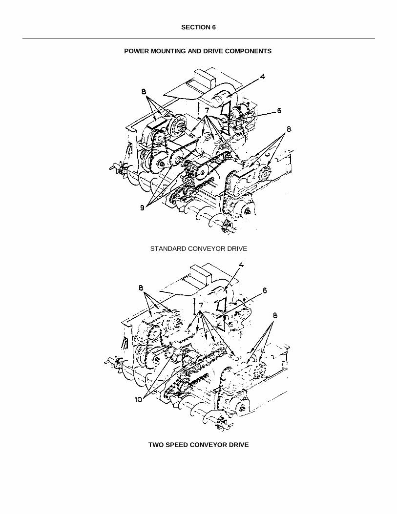
SECTION 6
POWER MOUNTING AND DRIVE COMPONENTS
STANDARD CONVEYOR DRIVE
TWO SPEED CONVEYOR DRIVE
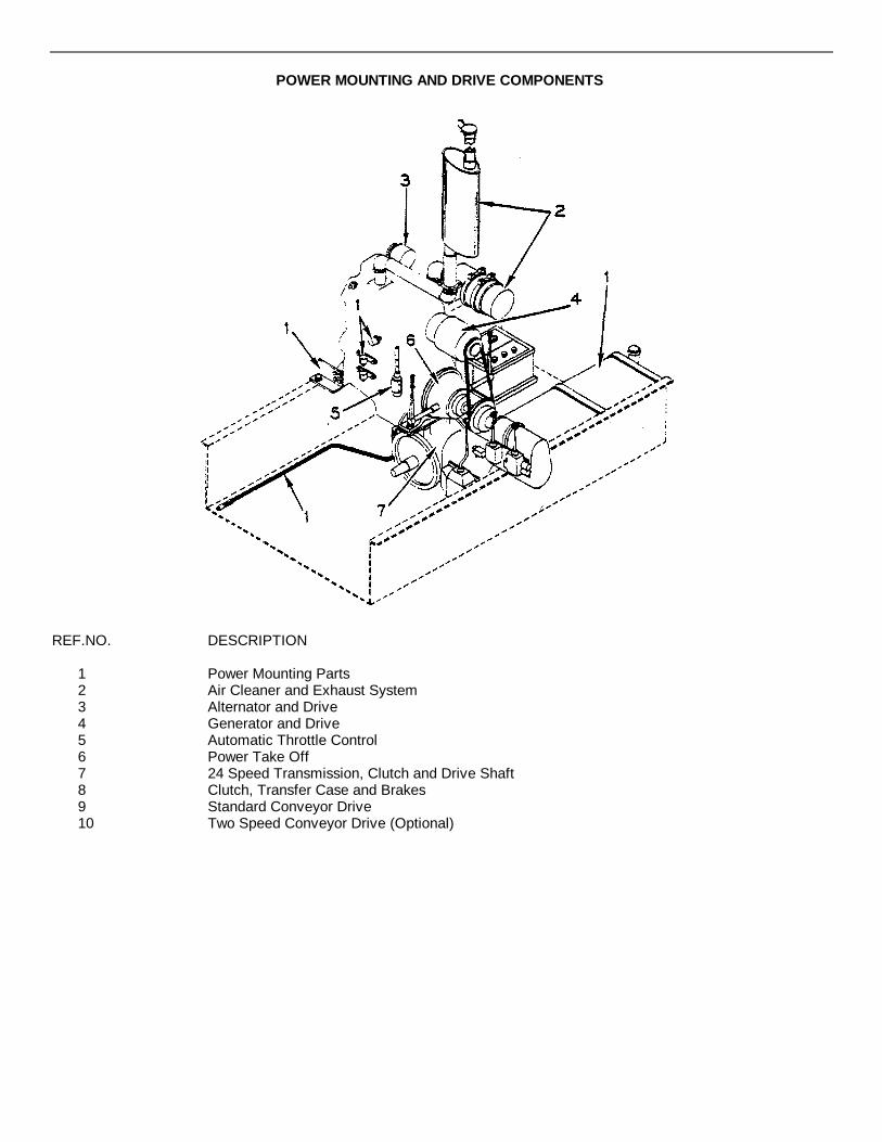
POWER MOUNTING AND DRIVE COMPONENTS
REF.NO. DESCRIPTION
1 Power Mounting Parts2 Air Cleaner and Exhaust System3 Alternator and Drive4 Generator and Drive5 Automatic Throttle Control6 Power Take Off7 24 Speed Transmission, Clutch and Drive Shaft8 Clutch, Transfer Case and Brakes9 Standard Conveyor Drive10 Two Speed Conveyor Drive (Optional)
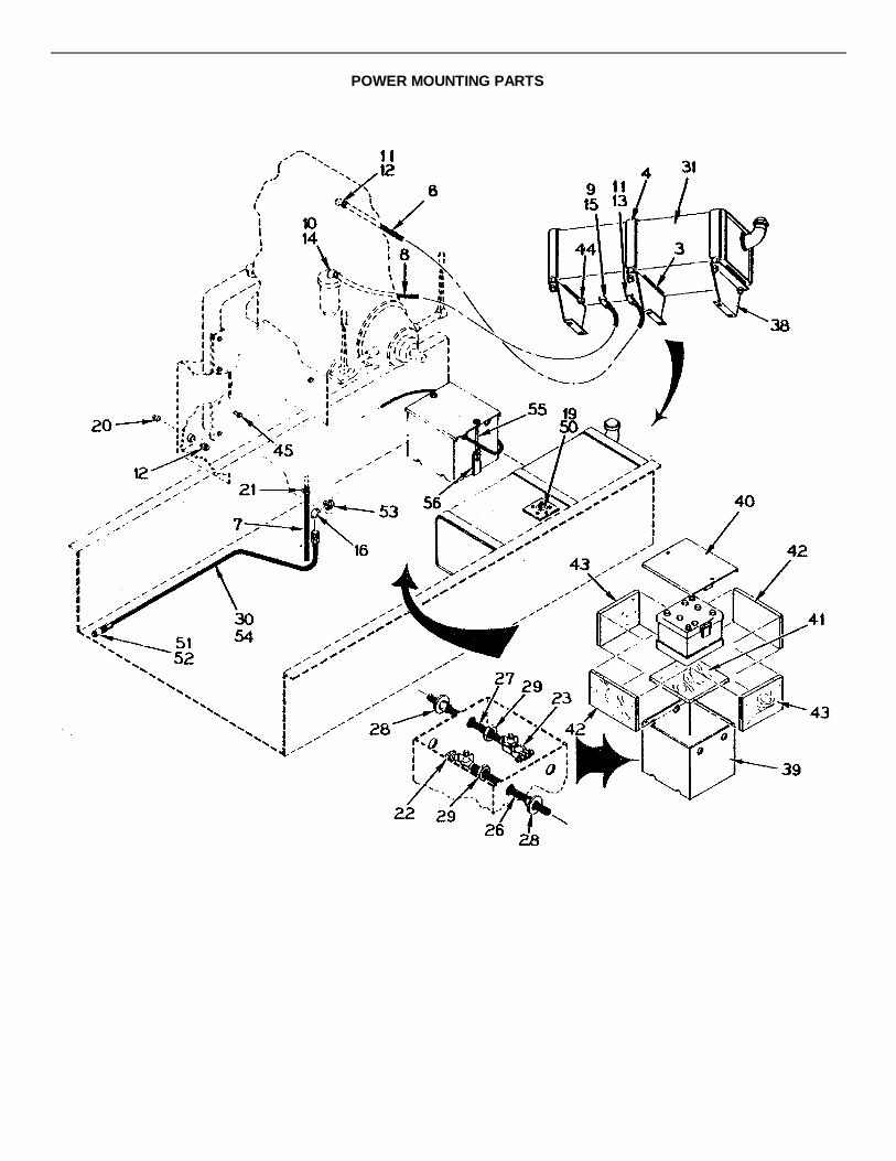
POWER MOUNTING PARTS
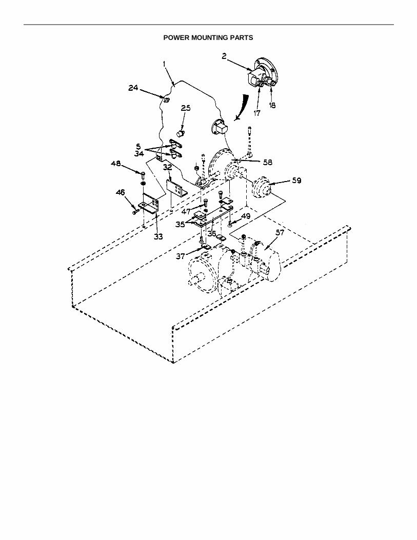
POWER MOUNTING PARTS

POWER MOUNTING PARTS
REF.NO. PART NUMBER DESCRIPTION QUANTITY
1 45924-008-02 Power MountingMake - GMC DieselModel # 3-53
12 45080-001-07 Pump, Hydraulic - See Form # 12560 -
This Section 13 41733-003-02 Tape, Anti Squeak 1/8" x 1½ " 3.0'4 5036GD21A Strap, Tank 35 46325-002-09 Relay, Magnetic Continuous 26 50030-002-01 Hose, ¼" ID x 5'-6" 5.5'7 50030-002-01 Hose, ¼" ID x 24" 2.0'8 50030-002-02 Hose, 3/8" ID x 4'-6" 4.5'9 7431-004 Hose End, 3/8" NPT Rigid Male 110 7431-008 Hose End, 3/8" NPT Sy. Female 111 7431-006 Hose End, ¼" Swivel Female 212 7430-002 Connector, ¼" Tube ¼" Pipe 213 7430-017 Elbow, 90° ¼" Tube x ¼" Pipe 114 7430-019 Elbow, 90° 3/8" Tube x 3/8" Pipe 115 45191-501-08 Elbow, 90° 3/8" 116 7430-022 Fitting, 90° ½ " MP x ½ " 37° 117 7430-007 Fitting, Straight ,½ " MP x ½ " 37° 118 45191-250-07 Fitting, Straight 1" MP x 1" Hose 119 9704-302-06 Sender, Fuel 120 7024-002 Plug, ¼" NPT 121 45191-004-28 Clamp, Hose 122 7296-006 Terminal, Stud Type - Negative 123 7296-005 Terminal, Stud Type - Positive 124 45865-003-03 Sensor, Temp Sending 125 45865-002-17 Sensor, Oil Pressure Sending 126 5008U20U Cable, Battery 127 5008U20T Cable, Battery - Starter 128 46026-004-03 Bushing, Male Fiber 229 46026-016-03 Locknut, Conduit 230 9701-416 Hose - Complete 1
50036-070-00 Hose, ½ " ID x 70" 145191-503-13 Male Pipe End 145191-503-15 Swivel Fitting JIC 37° 1
31 9704-302-05 Tank, Modified Fuel 132 9704-300-50 Bracket, Engine Mount 133 9704-300-51 Bracket, Engine Mount 134 9704-300-52 Bracket, Relay Mount 2
5036GF10 Shim, 1/8" As Req.35 5036GF11 Shim, 1/16" As Req.
5036GF12 Shim, 1/32" As Req.36 5036GF31 Support, Engine - Rear 1
-Continued-
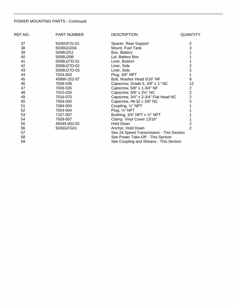
POWER MOUNTING PARTS - Continued
REF.NO. PART NUMBER DESCRIPTION QUANTITY
37 5036GF31-01 Spacer, Rear Support 238 5036GD20A Mount, Fuel Tank 339 5008U25J Box, Battery 140 5008U26B Lid, Battery Box 141 5008U27D-01 Liner, Bottom 142 5008U27D-02 Liner, Side 243 5008U27D-03 Liner, Side 244 7024-003 Plug, 3/8" NPT 145 45890-252-07 Bolt, Washer Head 5/16" NF 846 7838-038 Capscrew, Grade 5, 3/8" x 1" NC 1247 7009-026 Capscrew, 5/8" x 1-3/4" NF 248 7010-035 Capscrew, 5/8" x 2¼" NC 249 7016-075 Capscrew, 3/4" x 2-3/4" Flat Head NC 250 7504-050 Capscrew, #8-32 x 3/8” NC 551 7084-004 Coupling, ½ " NPT 152 7024-004 Plug, ½ " NPT 153 7107-007 Bushing, 3/4" NPT x ½ " NPT 154 7509-007 Clamp, Vinyl Cover 13/16" 155 45045-002-02 Hold Down 256 5036GFG01 Anchor, Hold Down 257 See 24 Speed Transmission - This Section58 See Power Take-Off - This Section59 See Coupling and Sheave - This Section

HYDRAULIC PUMP
REF.NO. PART NUMBER DESCRIPTION QUANTITY
45080-001-07 Pump Assembly1 45080-500-17 Ring Snap 12 45080-504-01 Bearing 13 45080-507-05 Shaft 14 45080-506-05 Key 15 45080-502-07 Kit, Seal 16 45080-504-09 Bearing 17 45080-521-05 Body 18 45080-501-20 Bolt 29 45080-512-06 Pin 210 45080-511-02 Cartridge Kit 111 45080-513-10 Plate, Pressure 112 45080-517-08 Spring 113 45080-525-02 Cover 114 45080-525-03 Capscrew,-Cover 4
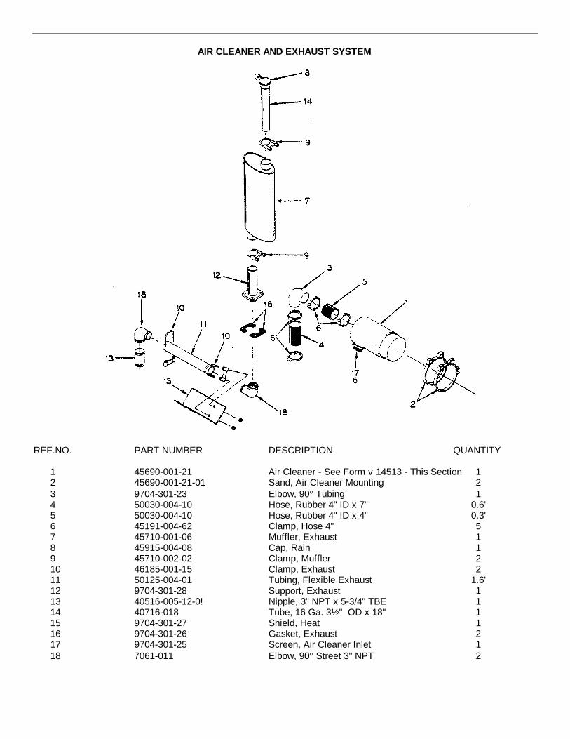
AIR CLEANER AND EXHAUST SYSTEM
REF.NO. PART NUMBER DESCRIPTION QUANTITY
1 45690-001-21 Air Cleaner - See Form v 14513 - This Section 12 45690-001-21-01 Sand, Air Cleaner Mounting 23 9704-301-23 Elbow, 90° Tubing 14 50030-004-10 Hose, Rubber 4" ID x 7" 0.6'5 50030-004-10 Hose, Rubber 4" ID x 4" 0.3'6 45191-004-62 Clamp, Hose 4" 57 45710-001-06 Muffler, Exhaust 18 45915-004-08 Cap, Rain 19 45710-002-02 Clamp, Muffler 210 46185-001-15 Clamp, Exhaust 211 50125-004-01 Tubing, Flexible Exhaust 1.6'12 9704-301-28 Support, Exhaust 113 40516-005-12-0! Nipple, 3" NPT x 5-3/4" TBE 114 40716-018 Tube, 16 Ga. 3½ " OD x 18" 115 9704-301-27 Shield, Heat 116 9704-301-26 Gasket, Exhaust 217 9704-301-25 Screen, Air Cleaner Inlet 118 7061-011 Elbow, 90° Street 3" NPT 2

AIR CLEANER
REF.NO. PART NUMBER DESCRIPTION QUANTITY
45690-001-21 Air Cleaner - Complete 11 * Body 12 45690-001-21-03 Element 13 45690-001-21-04 Kit, Nut and Gasket 14 &5690-001-21-05 Clamp 15 45690-001-21-06 Baffle 16 45690-001-21-07 Cup, Dust 1
*NOTE: The Body is not a service item. The manufacturer recommends replacement of entirecleaner if body is damaged.
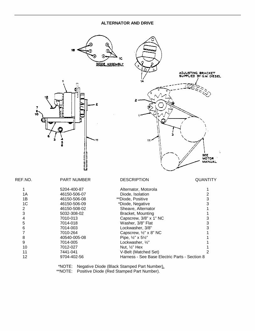
ALTERNATOR AND DRIVE
REF.NO. PART NUMBER DESCRIPTION QUANTITY
1 5204-400-87 Alternator, Motorola 11A 46150-506-07 Diode, Isolation 21B 46150-506-08 **Diode, Positive 31C 46150-506-09 *Diode, Negative 32 46150-508-02 Sheave, Alternator 13 5032-308-02 Bracket, Mounting 14 7010-013 Capscrew, 3/8" x 1" NC 35 7014-018 Washer, 3/8" Flat 36 7014-003 Lockwasher, 3/8" 37 7010-264 Capscrew, ½ " x 8" NC 18 40540-005-08 Pipe, ½ " x 5½ " 19 7014-005 Lockwasher, ½ " 110 7012-027 Nut, ½ " Hex 111 7441-041 V-Belt (Matched Set) 212 9704-402-56 Harness - See Base Electric Parts - Section 8
*NOTE: Negative Diode (Black Stamped Part Number),**NOTE: Positive Diode (Red Stamped Part Number).

GENERATOR AND DRIVE
REF.NO. PART NUMBER DESCRIPTION QUANTITY
1 46150-001-75 Generator - See Winpower Manual - This Section 12 01B04-002-03 Sheave 13 7401-018 Bushing 14 7118-031 Belt 15 9704-300-41 Support, Mounting 16 5036GE29 Bracket, Adjusting 17 5032-301-15 Clip, Generator Mounting 38 5032-301-21 Bracket, Rear 19 5032-301-22 Bracket, Front 110 7389-024 Capscrew, 3/8" x 1" Socket Flat Head NC 2
7007-140 Washer, 3/8" Shakeproof 211 See Coupling and Sheave - This Section12 7010-087 Capscrew, 3/8" x 5/8" NC 4
7014-001 Lockwasher, ¼” 47010-013 Capscrew, 3/8" x 1" NC 2
13 7014-003 Lockwasher, 3/8" 27014-018 Washer, 3/8" Flat 27383-040 Capscrew, Grade 5, 3/8" x 1½ " N C 3
14 7014-003 Lockwasher, 3/8" 37014-018 Washer, 3/8" Flat 37010-014 Capscrew, 3/8" x 1¼" NC 6
15 7012-025 Nut, 3/8" Hex NC 67014-003 Lockwasher, 3/8" 67014-018 Washer, 3/8" Flat 67010-021 Capscrew, ½ " x 1¼" NC 3
16 7012-027 Nut, ½ " Hex NC 37014-005 Lockwasher, ½ " 3
{
{
{{
{{

OPERATING AND MAINTENANCEINSTRUCTIONS
Model No.FM3V2-B/3
INSTRUCTION MANUAL
INTRODUCTION
The information in this manual covers revolving field type alternators using static excitation. This type of excitation willbe discussed in detail in later paragraphs of this manual. The information contained should be studied carefully and theinstruction book kept at hand for ready reference. Read very carefully the paragraphs on proper use and maintenance.
The equipment described is the result of careful engineering design and manufacturing techniques. It has beenthoroughly inspected and tested before shipment. Carefully inspect on delivery for evidence of shipping damage. Ifdamage has occurred it should be noted on the freight bill in order that acclaim can be filed to recover the cost of thedamage. If the damage appears to be of a major nature, the fault should be corrected before using.
If you wish to contact your dealer or the factory, make sure you mention the model and serial number as listed on thenameplate on the side of the alternator.
Winpower alternators are designed to deliver voltage and current identical to that of a normal power line. Equipment thatcan be operated on normal power can also be operated by the alternator, provided the capacity of the alternator is notexceeded. It should be remembered that the power line, for all practical purposes, is backed by an unlimited generator.
Promptly fill in and return the guarantee card enclosed in the front of the manual.
ALTERNATOR
The alternator is a revolving field type, using a static system for excitation and control of the voltage regulation. Thesection below describes the static excitation. The rotor in a two pole machine must revolve at 3600 RPM for 60 hertzcurrent and at 3000 RPM for 50 hertz. Frequency varies in direct relation to the speed of rotation. The governor of thedriving engine or tractor will therefore determine the variation in frequency. An unstable governor orone that droops in speed excessively under load will result in excessive frequency variation. A droop at 5% in speed willresult in a frequency variation of 3 hertz. This variation is of little consequence for most equipment to be powered. Thedriving engine should have sufficient power to maintain speed under load. The best of governors cannot control anoverloaded engine.
WHAT IS STATIC EXCITATION?
The word "static" means without motion; thus, the term "static excited" means that the control system which provides thecurrent for the electro-magnetic field is provided without the use of an out-moded revolving DC armature. Commutatorsand commutator brushes with the inherent problem of sparking and maintenance are eliminated. The use of amechanical voltage regulator with vibrating or multiple moving contacts is also eliminated.
- 2 -
Direct current is required for the electro-magnetic field. A single coil is wound in the alternator stator (the stationarywinding) to provide the current for the base field. This coil is entirely separate from the main winding and is at rightangles in mechanical position. The AC voltage generated in this coil is fed to a full wave silicon diode bridge to providerectified direct current for the base field. As the field is the rotating component, the current connection is accomplishedby the use of slip rings and brushes. The base field is connected to ring #1 (nearest to the bearing) and ring #3. Thebase field is designed to provide magnetic lines of force required to generate rated voltage with no load on the alternator.
In order to maintain close voltage regulation as the load is varied, a control field is used. The control circuit consists ofan additional full wave bridge, in series with one load line, and a control winding on the field poles. The control field isconnected to ring #1 and ring #2. When a load is connected to the alternator, this current is rectified and fed through thecontrol field winding. By this means, the total strength of the field is varied in relation to the load.
The description of static excitation opened with the statement that "static" is-defined as without motion. In laterparagraphs the revolving field has been discussed. To avoid confusion, a word of explanation is in order. There must besome relative motion between the coils which generate voltage and the magnetic field which causes the voltage to beproduced. In a revolving field generator, the winding that produces the voltage is stationary and the field poles revolve.The reverse is true in the case of a revolving armature generator; the field is stationary and the voltage producingwinding rotates.
LOAD CONNECTION
Standard connection for 2000 watt, single voltage alternators use duplex grounding type receptacles. Specialapplications, to be used as part of other equipment, may provide a plate to accept conduit fittings. Short leads arebrought out for connection.
Larger capacity machines are provided with an outlet box enclosing a terminal strip for connection. Optional panels areavailable for capacities above 2000 watts. These are designed to be installed in the field. A voltage indicator, a circuitbreaker, 15 ampere duplex receptacle and a 50 ampere receptacle are included in the special panels. The voltageindicator uses a color band of red and green in place of a numbered scale. Voltage and frequency are correct in thegreen portion of the color band.
MAINTENANCE
Little maintenance is required other than routine inspection and cleaning. The bearings are pre-lubricated and will be along life item unless damage by accident or excessive driving belt tension.
The interior of the alternator should be clean and unobstructed. Slip rings and brushholders should be kept free from dirt,oil and moisture. If compressed air is available it can be used effectively for cleaning.
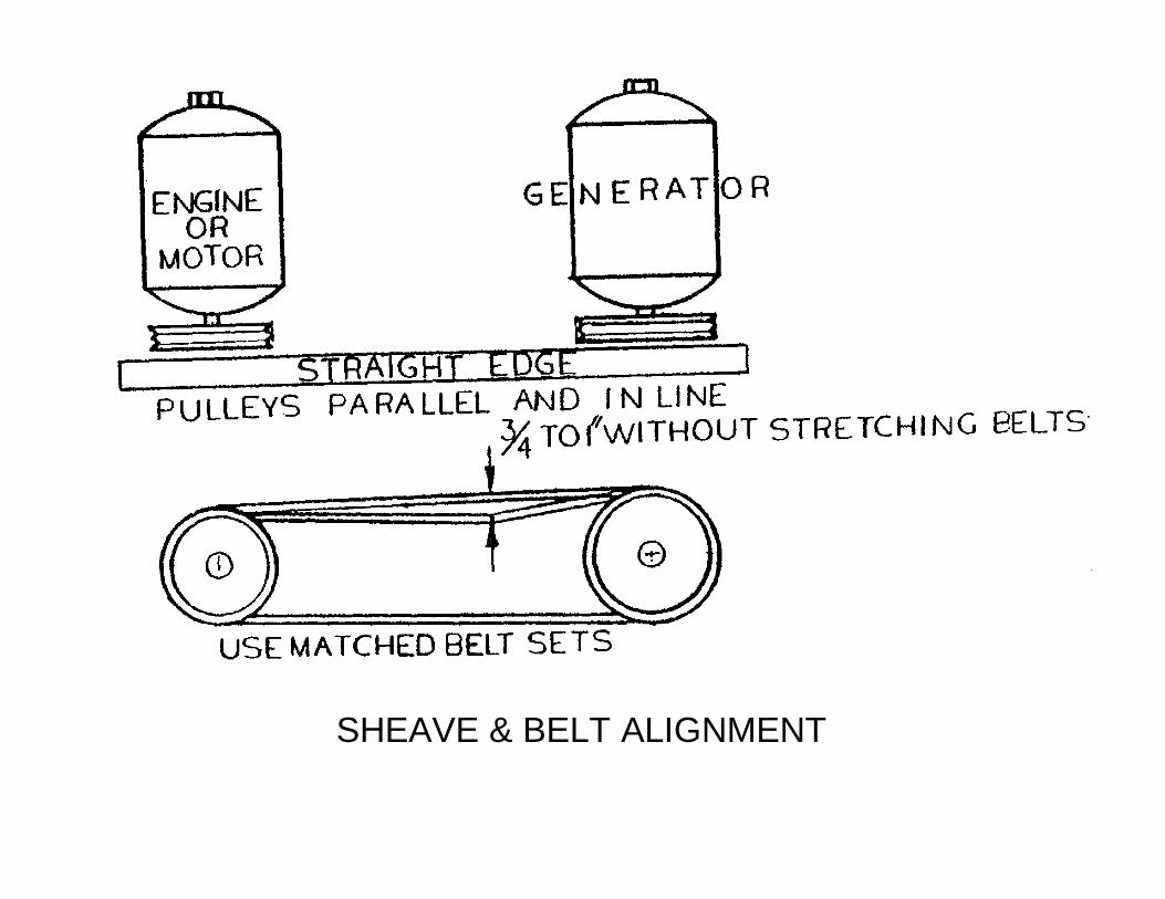
SHEAVE & BELT ALIGNMENT

LOW OUTPUT VOLTAGEPOSSIBLE CAUSE REMEDY
Low Speed 1. Check for overload on the engine.2. Defective governor. Check governor spring
ension, tight or defective throttle leverand joints.
3. Defective engine.High line loss. Indicated by lower voltage at Increase size of line wiring. Might also beload than at generator terminals. the result of loose connections which will be
indicated by excessive heating at the looseconnections.
Shorted or grounded field coil. In some cases See information for testing field circuits.one coil only, that is shorted or grounded,will reduce voltage to approximately one halfof rating.Defective compound field circuit. Field See information for testing field circuits.connected to Rings #1 and *2.Defective control field bridge. See information on-testing bridge assemblies.
HIGH OUTPUT VOLTAGEExcessive speed Check governor linkage, spring tension, etc.
Governor linkage must be free from dirt & gum.EXCESSIVE HEATING
Clogged ventilating inlet and/or outlet. Clean. Make sure interior is unobstructed.-Excessive heat from other equipment Construct baffle or some means to direct heat
in another direction.Overload Reduce load.
NO OUTPUT VOLTAGEPoor Brush Contact: Brushes tight in holder. Clean Brushholder. Brush should move freely
in holder.Weak Brush Spring Tension Brush spring tension should snap brush into
contact with ring when lifted and released.Film on Collector Rings caused by corrosive Clean rings with fine sandpaper during rotation.or dirty atmosphere. Caution: Tape sandpaper to stiff cardboard for
safety.Defective Rectifier Bridge (See illustration Replace defective bridge assembly. Find assem-for method of checking bridge.) bly number under DIODE ASSEMBLY in parts list.Openifield circuit (See illustration for Replace Rotor Assembly.method for checking.)Grounded or shorted field coil(s) (See illus- Replace Rotor Assembly.tration for method.)Loss of residual magnetism. This is a condi- See note under field assembly for proceduretion brought about by some unusual condition. to restore magnetism.It will always occur after disassembly.Defective Stator:Shorted winding. This can be identified by theuse of a "growler" at a competent rewindingshop Replace the Stator. See illustration forGrounded winding. Check by test lamp from testing method. (Include generator modelstator winding to frame and serial number on the order.)Open winding circuit. Check all circuits forcontinuity IE: S2 to S1, S4 to L1.
Step by Step Check List
1. Check alternator shaft speed. Should be 3600 RPM, 60 hertz at full load.
2. Check voltage output at terminal ends of Lines L1 and L2. If volt-age is correct at this point, make a progressive check from this point through the wiring system.
3. Check brush contact to rings. Brushes and holders should be free from dirt. Brush should snap back when lifted and released. Using caution to prevent scratching the ring or chipping the brush, a thin knife edge can be inserted for lifting the brush.
4. Inspect all wiring for loose or broken connection. Look for loose or broken solder joints. If a solder joint needs repairing on a diode, use a hot iron to accomplish repair quickly. Blow on the joint for quick cooling. Diodes can be destroyed by prolonged heat.
5. Check diodes. (See method outlined under Bridge Assemblies). Isolate all brushes from the rings by inserting heavy paper under the brush. Remove one quick disconnect clip from the base field bridge. This will isolate all parallel circuits.
6. Before removing the paper insulation from under brushes, check out the rotor as outlined under Field Assembly. If voltage is correct at no load but drops excessively on load, and correct speed is maintained, suspect the control field or the control field connections.
7. When the voltage at correct speed is very low at no load and approximately 50% of rating on load, the base stator winding may be open. Check for a circuit between the brown leads connected to the base field bridge. Disconnect one lead before making check.
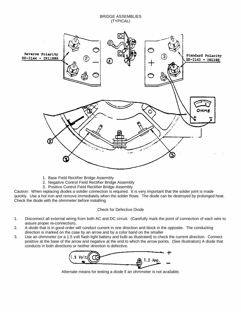
BRIDGE ASSEMBLIES(TYPICAL)
1. Base Field Rectifier Bridge Assembly2. Negative Control Field Rectifier Bridge Assembly3. Positive Control Field Rectifier Bridge Assembly
Caution: When replacing diodes a solider connection is required. It is very important that the solder joint is madequickly. Use a hot iron and remove immediately when the solder flows. The diode can be destroyed by prolonged heat.Check the diode with the ohmmeter before installing.
Check for Defective Diode
1. Disconnect all external wiring from both AC and DC circuit. (Carefully mark the point of connection of each wire to assure proper re-connection).
2. A diode that is in good order will conduct current in one direction and block in the opposite. The conducting direction is marked on the case by an arrow and by a color band on the smaller
3. Use an ohmmeter (or a 1.5 volt flash light battery and bulb as illustrated) to check the current direction. Connect positive at the base of the arrow and negative at the end to which the arrow points. (See illustration) A diode that conducts in both directions or neither direction is defective.
Alternate means for testing a diode if an ohmmeter is not available.

BRUSHHOLDER ASSEMBLY
Models rated at 2000 watts and under use one bracket assembly 2 as shown in solid lines. Models above that ratinghave two brushes on rings #1 and #2 (numbering from end of shaft) and use added bracket 1 as shown in dotted lines.
Note: When replacing brushes, the most simple method is todisconnect the entire bracket assembly by removingthe screw at each end. The bracket can then be tiltedforward for easy access to the brushholder caps.
1. A-745 Brushholder bracket (right) 6. Y-114 Brush2. A-746 Brushholder bracket (left) 7. S-6096 Clamp3. B-701 Brushholder 8. *2005 Screws4. B-791-A Cap 9. #1110 Lock Washer5. B-701-B Clip 10. #2652 Screw - Self tapping

FIELD ASSEMBLY
Resistance of Field Circuits at 25°C -(77°F)
Model Base Field (Ring #1 to 3) Control Field (Ring #1 to 2)FM3V2-B/3 43 to 53 ohms Less than 1 ohmFM2V2-B 32 to 42 ohms Less than 1 ohmFM4V2-B 43 to 53 ohms Less than 1 ohmFM4V2-C 43 to 53 ohms Less than 1 ohmFM6V2-C 47 to 57 ohms Less than 1 ohm
Note: When ordering replacement field assemblies, be sure to include model and serial number from nameplate on alternator frame.
TESTING A FIELD CIRCUIT
Make sure that all brushes are not in contact with the slip rings. If the alternator has not been disassembled, paperinserted between the brush and slip ring will serve as insulation. The complete brushholder bracket can be removed ifthis procedure is preferred, by removing the screws and nuts at each end of the bracket. The brush gear may use onebracket or two brackets, depending on the capacity of the alternator. When two are used, both must be insulated ordisconnected.
To measure the resistance of the base field, touch the ohmmeter leads to ring #1 and #3 as shown in the illustration.Measure from rings #1 and #2 for the control field.
A resistance appreciably lower than shown on the table indicates shorted turns in one or both field coils. The resistanceof less than one ohm on the control field is too low to measure accurately with the average ohmmeter. A complete circuitbetween rings should be indicated. A high resistance would indicate a broken connection.
A grounded field circuit can be identified by connecting the meter from the slip rings to the rotor shaft.
NOTE: Occasionally an alternator will lose residual magnetism. It is very unusual unless the alternator has beendisassembled, in which case it will be necessary to "flash the field" on the first start.
(continued)
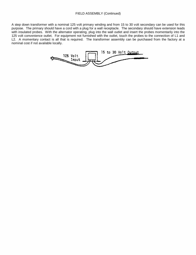
FIELD ASSEMBLY (Continued)
A step down transformer with a nominal 125 volt primary winding and from 15 to 30 volt secondary can be used for thispurpose. The primary should have a cord with a plug for a wall receptacle. The secondary should have extension leadswith insulated probes. With the alternator operating, plug into the wall outlet and insert the probes momentarily into the125 volt convenience outlet. For equipment not furnished with the outlet, touch the probes to the connection of L1 andL2. A momentary contact is all that is required. The transformer assembly can be purchased from the factory at anominal cost if not available locally.

STATOR ASSEMBLY
Note: When ordering replacement stator assemblies be sure to include the model and serial number from the nameplate on the side of the generator.
The stator assembly has a winding to develop voltage for the base field. The lead extensions from this winding arecolored brown. Connection from this winding is to the base bridge.
A single, two pole winding is used for two wire, single voltage models. This winding connects to the control (Series) fieldbridge. The control bridge is divided into a positive and a negative side and is in series with the load. (See bridgeassembly illustration)
Three wire, dual voltage models use two identical, two pole windings. Each winding generates 125 volts. The voltagefrom either line to neutral is, therefore, 125. From L1 to L: the winding is in series for 250 volt output.
When a fault in the stator is suspected each individual winding should be checked. The resistance of 'the separatewindings will be low, less than one ohm, but a complete circuit should be indicated. IE: #S1 to #S2, #S4 to #L1.
The various windings should also be checked for ground. For this purpose connect an ohmmeter from a bare spot on theframe to one lead of each coil. A meter deflection indicates a grounded winding.
When all stator leads are disconnected, there should be no circuit from one winding to any other. If a circuit is indicated,the winding is shorted.
If any of the above conditions are indicated, the stator assembly must be replaced.

PARTS LIST PL-01229FM3V2-B/3
(IOWA MFG. CO.)46150-001-75
FIND NO. PART NO. DESCRIPTION REQ'D/UNIT
1 G-5208-9 Stator Frame Assembly 12 G-5285-2 Rotor Assembly 13 D-59 Bearing 24 11099 Retaining Ring 25 A-722-5 Drive End Bell 16 S-6242 Bearing Retainer 27 G-4799-3 Bearing End Bell Assembly 18 A-726-3 End Bell 19 A-746 Brushholder Bracket 19a A-745 Brushholder Bracket 1
10 B-701 Brushholder 511 B-701-1 Brushholder Cap 512 B-701-2 Brushholder Clip 513 Y-114 Brush 514 S-6096 Clamp 515 G-5298-3 Rectifier Assembly (Neg.) 116 G-5297-3 Rectifier Assembly (Pos.) 117 EE-2171 Rectifier Assembly (Shunt) 118 J-545 Board, Insulating 119 J-546 Bushing 420 4074-2 Screw 1/4-20 x 7-1/2 121 4074-4 Screw 1/4-20 x 6-1/2 322 A-727 Fan 123 V-1059 End Hood 124 V-1085 Handy Box 125 EE-910 Cover 126 S-6982-1 Cover Plage 1
Wiring Diagram E-7374PARTS DRAWING E-8594

E-8594
E-8594

E-7
E-7374

AUTOMATIC THROTTLE CONTROL

AUTOMATIC THROTTLE CONTROL
REF.NO. PART NUMBER DESCRIPTION QUANTITY
5036XG21 Bracket, Solenoid 11 7436-093 Screw, #10-32 x 3/8" 4
7439-003 Lockwasher, #10 47014-043 Washer, 3/16" Flat 1
2 46205-001-12 Solenoid 13 7012-046 Nut, 5/16" NF 14 9704-300-85 Coupler, Threaded 15 5036XG23 Link, Throttle 16 5036XG24 Pin, Lower Link 17 5036XG25 Pin, Upper Link 18 7011-001 Pin, Cotter 3/32" x 1" 29 5036XG26 Lever, Throttle 110 7025-001 Capscrew, ¼" x 3/4" Nylok Socket Head 111 7014-001 Lockwasher, ¼" 212 5036XG27 Bracket, Idler Stop 113 7072-054 Bolt, Carriage 3/8" x 1½ " NC 114 7012-025 Nut, 3/8" Hex NC 115 7010-014 Capscrew, 3/8" x 1¼" NC 216 7014-003 Lockwasher, 3/8" 417 45870-001-19 Spring 118 5036XG01-08 Clamp, Bowden Wire 119 7010-087 Capscrew, ¼" x 5/8" NC 120 7012-023 Nut, ¼" NC 121 7014-017 Washer, 5/16" Flat 322 7010-015 Capscrew, 3/8" x 1½ " NC 223 5036XG01-10 Lever, Fuel Stop 124 5036XD12 Collar Set 125 7435-071 Screw, #8-32 x ¼" 126 7026-003 Capscrew, 1/4" x 1¼" Socket Head NF 127 7012-045 Nut, ¼" NF 128 7438-007 Washer, ¼" Shakeproof 1
{

POWER TAKE-OFFDIESEL ENGINE
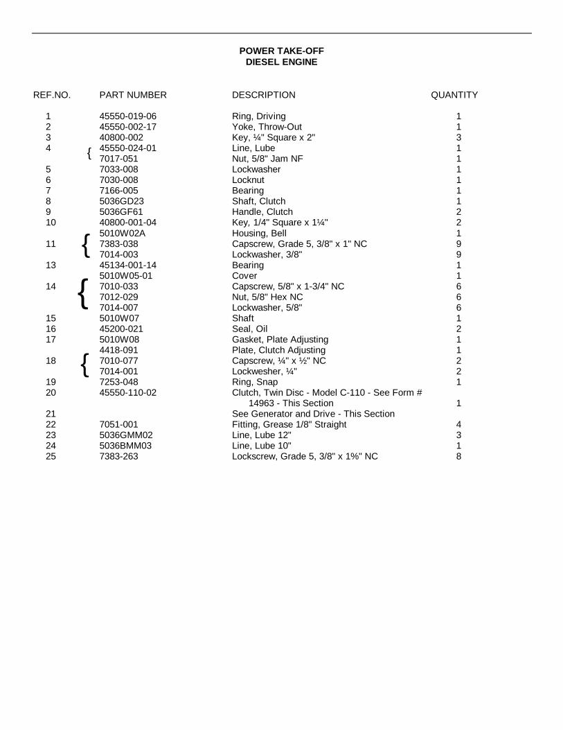
POWER TAKE-OFFDIESEL ENGINE
REF.NO. PART NUMBER DESCRIPTION QUANTITY
1 45550-019-06 Ring, Driving 12 45550-002-17 Yoke, Throw-Out 13 40800-002 Key, ¼" Square x 2" 34 45550-024-01 Line, Lube 1
7017-051 Nut, 5/8" Jam NF 15 7033-008 Lockwasher 16 7030-008 Locknut 17 7166-005 Bearing 18 5036GD23 Shaft, Clutch 19 5036GF61 Handle, Clutch 210 40800-001-04 Key, 1/4" Square x 1¼" 2
5010W02A Housing, Bell 111 7383-038 Capscrew, Grade 5, 3/8" x 1" NC 9
7014-003 Lockwasher, 3/8" 913 45134-001-14 Bearing 1
5010W05-01 Cover 114 7010-033 Capscrew, 5/8" x 1-3/4" NC 6
7012-029 Nut, 5/8" Hex NC 67014-007 Lockwasher, 5/8" 6
15 5010W07 Shaft 116 45200-021 Seal, Oil 217 5010W08 Gasket, Plate Adjusting 1
4418-091 Plate, Clutch Adjusting 118 7010-077 Capscrew, ¼" x ½ " NC 2
7014-001 Lockwesher, ¼" 219 7253-048 Ring, Snap 120 45550-110-02 Clutch, Twin Disc - Model C-110 - See Form #
14963 - This Section 121 See Generator and Drive - This Section22 7051-001 Fitting, Grease 1/8" Straight 423 5036GMM02 Line, Lube 12" 324 5036BMM03 Line, Lube 10" 125 7383-263 Lockscrew, Grade 5, 3/8" x 1%" NC 8
{
{
{
{
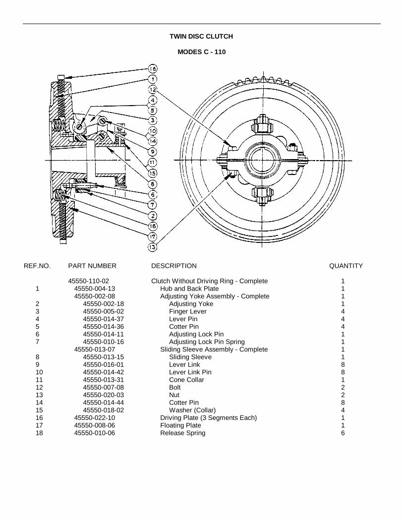
TWIN DISC CLUTCH
MODES C - 110
REF.NO. PART NUMBER DESCRIPTION QUANTITY
45550-110-02 Clutch Without Driving Ring - Complete 11 45550-004-13 Hub and Back Plate 1
45550-002-08 Adjusting Yoke Assembly - Complete 12 45550-002-18 Adjusting Yoke 13 45550-005-02 Finger Lever 44 45550-014-37 Lever Pin 45 45550-014-36 Cotter Pin 46 45550-014-11 Adjusting Lock Pin 17 45550-010-16 Adjusting Lock Pin Spring 1
45550-013-07 Sliding Sleeve Assembly - Complete 18 45550-013-15 Sliding Sleeve 19 45550-016-01 Lever Link 810 45550-014-42 Lever Link Pin 811 45550-013-31 Cone Collar 112 45550-007-08 Bolt 213 45550-020-03 Nut 214 45550-014-44 Cotter Pin 815 45550-018-02 Washer (Collar) 416 45550-022-10 Driving Plate (3 Segments Each) 117 45550-008-06 Floating Plate 118 45550-010-06 Release Spring 6
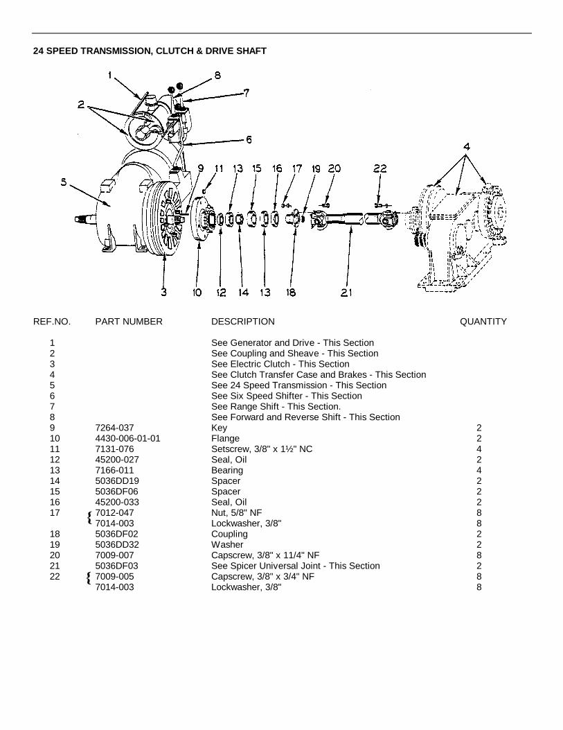
24 SPEED TRANSMISSION, CLUTCH & DRIVE SHAFT
REF.NO. PART NUMBER DESCRIPTION QUANTITY
1 See Generator and Drive - This Section2 See Coupling and Sheave - This Section3 See Electric Clutch - This Section4 See Clutch Transfer Case and Brakes - This Section5 See 24 Speed Transmission - This Section6 See Six Speed Shifter - This Section7 See Range Shift - This Section.8 See Forward and Reverse Shift - This Section9 7264-037 Key 210 4430-006-01-01 Flange 211 7131-076 Setscrew, 3/8" x 1½ " NC 412 45200-027 Seal, Oil 213 7166-011 Bearing 414 5036DD19 Spacer 215 5036DF06 Spacer 216 45200-033 Seal, Oil 217 7012-047 Nut, 5/8" NF 8
7014-003 Lockwasher, 3/8" 818 5036DF02 Coupling 219 5036DD32 Washer 220 7009-007 Capscrew, 3/8" x 11/4" NF 821 5036DF03 See Spicer Universal Joint - This Section 222 7009-005 Capscrew, 3/8" x 3/4" NF 8
7014-003 Lockwasher, 3/8" 8

COUPLING AND SHEAVE
REF.NO. PART NUMBER DESCRIPTION QUANTITY
1 45476-001-02 *Coupling - Complete With Bolts 12 45476-502-04 *Bolt Set (Only) 43 4431-038-01 Flange 14 4430-008-01 Sheave 15 40803-002-12 Key, 1/2" x 1/2" x 2-3/4" 16 40802-002-08 Key, 3/8" x 3/8" x 2 1/2)'" 17 7131-074 Setscrew, 3/8" x 3/8" NC 28 7131-077 Setscrew, 3/8" x 5/8" NC 2
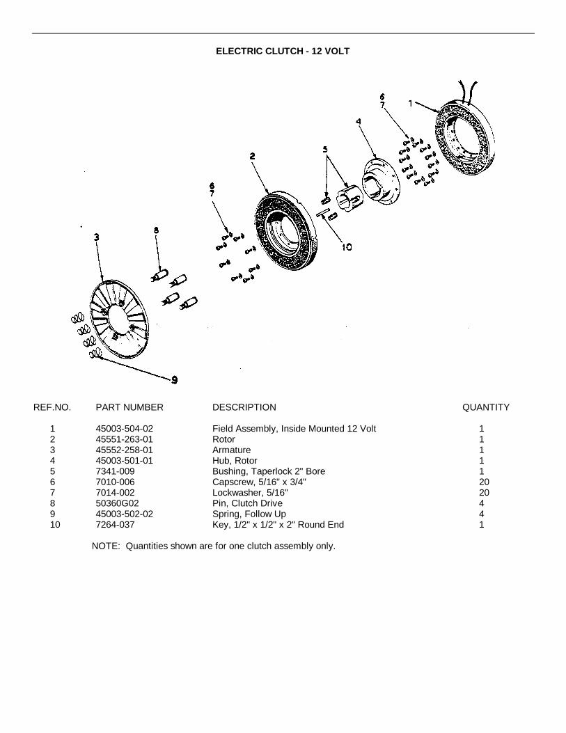
ELECTRIC CLUTCH - 12 VOLT
REF.NO. PART NUMBER DESCRIPTION QUANTITY
1 45003-504-02 Field Assembly, Inside Mounted 12 Volt 12 45551-263-01 Rotor 13 45552-258-01 Armature 14 45003-501-01 Hub, Rotor 15 7341-009 Bushing, Taperlock 2" Bore 16 7010-006 Capscrew, 5/16" x 3/4" 207 7014-002 Lockwasher, 5/16" 208 50360G02 Pin, Clutch Drive 49 45003-502-02 Spring, Follow Up 410 7264-037 Key, 1/2" x 1/2" x 2" Round End 1
NOTE: Quantities shown are for one clutch assembly only.

24 SPEED TRANSMISSION
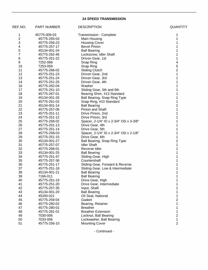
24 SPEED TRANSMISSION
REF.NO. PART NUMBER DESCRIPTION QUANTITY
1 45775-009-03 Transmission - Complete 12 45775-255-03 Main Housing 13 45775-256-23 Housing Cover 14 45775-257-17 Bevel Pinion 15 45134-001-24 Ball Bearing 17 45775-262-46 Lockscrew, Idler Shaft 18 45775-251-22 Driven Gear, 1st 19 7252-068 Snap Ring 410 7253-059 Snap Ring 511 45775-266-02 Sliding Clutch 212 45775-251-23 Driven Gear, 2nd 113 45775-251-24 Driven Gear, 3rd 114 45775-251-25 Driven Gear, 4th 116 45775-262-04 Washer 117 45775-251-10 Sliding Gear, 5th and 6th 118 45775-267-01 Bearing Shim, #13 Standard 119 45134-001-26 Ball Bearing, Snap Ring Type 120 45775-261-02 Snap Ring, #10 Standard 121 45134-001-14 Ball Bearing 222 45775-257-06 Pinion and Shaft 123 45775-251-11 Drive Pinion, 2nd 124 45775-251-12 Drive Pinion, 3rd 125 45775-258-02 Spacer, 2-1/4" ID x 2-3/4" OD x 3-3/8" 126 45775-251-13 Drive Gear, 4th 127 45775-251-14 Drive Gear, 5th 128 45775-258-03 Spacer, 2-1/4" ID x 2-3/4" OD x 2-1/8" 129 45775-251-15 Drive Gear, 6th 130 45134-001-27 Ball Bearing, Snap Ring Type 231 45775-257-07 Idler Shaft 132 45775-268-01 Reverse Idler 133 45134-001-25 Ball Bearing 134 45775-251-47 Sliding Gear, High 135 45775-257-36 Countershaft 136 45775-251-17 Sliding Gear, Forward & Reverse 137 45775-251-18 Sliding Gear, Low & Intermediate 138 45134-001-21 Ball Bearing 139 7166-011 Ball Bearing 140 45775-251-19 Drive Gear, High 141 45775-251-20 Drive Gear, Intermediate 142 45775-257-35 Input, Shaft 143 45134-001-20 Ball Bearing 144 45200-021 Oil Seal, National 145 45775-259-04 Gasket 246 45775-260-02 Bearing, Retainer 147 45775-280-01 Breather 148 45775-281-01 Breather Extension 149 7030-006 Locknut, Ball Bearing 250 7033-006 Lockwasher, Ball Bearing 151 45775-256-10 Mounting Cover 2
- Continued -
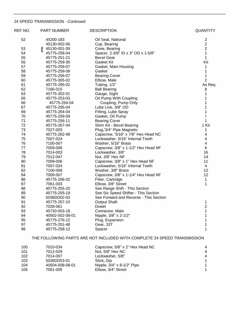
24 SPEED TRANSMISSION - Continued
REF.NO. PART NUMBER DESCRIPTION QUANTITY
52 45200-183 Oil Seal, National 245130-002-06 Cup, Bearing 2
53 45130-001-09 Cone, Bearing 254 45775-258-04 Spacer, 2-3/8" ID x 3" OD x 1-5/8" 155 45775-251-21 Bevel Gear 156 45775-259-30 Gasket Kit Kit57 45775-259-07 Gasket, Main Housing 158 45775-259-08 Gasket 159 45775-256-07 Bearing Cover 160 45775-305-02 Elbow, Male 261 45775-295-02 Tubing, 1/2" As Req.62 7166-015 Ball Bearing 863 45775-302-01 Gauge, Sight 165 45775-253-03 Oil Pump With Coupling 166 45775-254-04 Coupling, Pump Only 167 45775-295-04 Lube Line, 3/8" OD 169 45775-264-04 Fitting, Lube Spray 170 45775-259-09 Gasket, Oil Pump l71 45775-256-11 Bearing Cover 172 45775-267-04 Shim Kit - Bevel Bearing 1 Kit73 7027-003 Plug,'3/4" Pipe Magnetic 174 45775-262-48 Capscrew, '5/16" x 7/8" Hex Head NC 475 7007-024 Lockwasher, 5/16" Internal Teeth 476 7100-007 Washer, 5/16" Brass 477 7009-008 Capscrew, 3/8" x 1-1/2" Hex Head NF 678 7014-003 Lockwasher, 3/8" 1679 7012-047 Nut, 3/8" Hex NF 1480 7009-006 Capscrew, 3/8" x 1" Hex Head NF 1181 7007-024 Lockwasher, 5/16" Internal Teeth 482 7100-008 Washer, 3/8" Brass 1284 7009-007 Capscrew, 3/8" x 1-1/4" Hex Head NF 1286 45775-296-02 Filter, Cartridge 187 7061-003 Elbow, 3/8" Street 188 45775-255-20 See Range Shift - This Section89 45775-255-19 See Six Speed Shifter - This Section90 5036DD02-03 See Forward and Reverse - This Section91 45775-257-10 Output Shaft 192 7028-061 Dowel 293 45720-003-18 Connector, Male 194 40502-002-08-01 Nipple, 3/8" x 2-1/2" 195 45775-276-12 Plug, Expansion 197 45775-251-48 Gear, 33T 198 45775-258-12 Spacer 1
THE FOLLOWING PARTS ARE NOT INCLUDED WITH COMPLETE 24 SPEED TRANSMISSION
100 7010-034 Capscrew, 5/8" x 2" Hex Head NC 4101 7012-029 Nut, 5/8" Hex NC 4102 7014-007 Lockwasher, 5/8" 4103 5036DD53-01 Stick, Dip 1104 40504-008-08-01 Nipple, 3/4" x 8-1/2" Pipe 1105 7061-005 Elbow, 3/4" Street 1

RANGE SHIFT

RANGE SHIFT
REF.NO. PART NUMBER DESCRIPTION QUANTITY
45775-255-20 Range Shifter Assembly 11 45775-255-13 Housing, Range Shift 12 45775-259-46 Gasket, Range Shift Housing 13 45775-259-11 Gasket,-Shifter Cover 14 45775-256-30 Cover, Shifter 15 45775-269-02 Shift Lever, Range 16 45775-270-01 Spring, Shift Shaft 17 45775-262-03 Washer, Shift Cap 18 45775-273-01 Cap, Shift Housing 19 45775-252-01- Ball, Shift Lever 110 45775-257-38 Shifter Shaft, High 111 45775-257-37 Shifter Shaft, Low and Intermediate 112 45775-276-01 Expansion Plug, 1-1/8" 213 45775-271-04 Fork, High 114 45775-271-14 Fork, Low and Intermediate 115 45775-274-02 Plunger, Interlock 216 45775-270-03 Spring 117 45775-277-01 Ball 218 45775-260-03 Retainer, Spring 219 45250-020-04 Plug, 1/2" Pipe 120 7011-064 Pin, Cotter 1/8" x 2" 121 7064-016 Capscrew, 1/2" x 1-3/4" Hex Head NF 222 7010-013 Capscrew, 3/8" x 1" Hex Head NC 824 45775-276-02 Expansion Plug, 1-1/4" 825 45775-270-04 Spring 226 7007-031 Lockwasher, Internal Teeth 1-1/4" OD 227 45775-278-03 Nut, 3/4" Hex Jam NF 228 45775-282-01 Boot, Cover 129 45775-261-04 Clamp, Boot 130 7014-003 Lockwasher, 3/8" 8
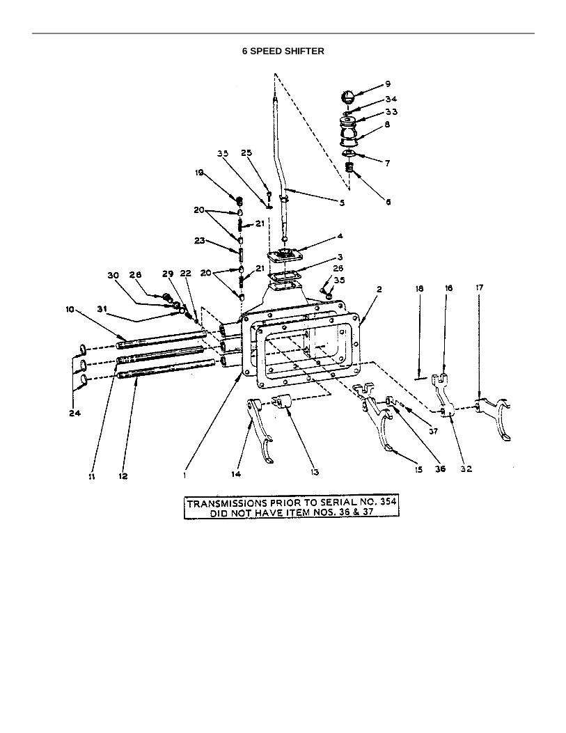
6 SPEED SHIFTER

6 SPEED SHIFTER
REF.NO. PART NUMBER DESCRIPTION QUANTITY
45775-255-19 Six Speed Shifter - Complete 11 45775-255-04 Housing 12 45775-259-10 Gasket 13 45775-259-11 Gasket, Shifter Cover 14 45775-256-09 Cover, Shifter 15 45775-269-01 Shift Lever, Six Speed 16 45775-270-01 Spring, Shift Shaft 17 45775-262-03 Washer, Shift Cap 18 45775-273-01 Cap, Shift Housing 19 45775-252-01 Ball, Shift Lever 110 45775-257-11 Shifter Shaft, 5th and 6th 111 45775-257-12 Shifter Shaft, 3rd and 4th 112 45775-257-13 Shifter Shaft, 1st and 2nd 113 45775-272-01 Shifter Dog, 5th and 6th 114 45775-271-01 Fork, 5th and 6th 115 45775-271-02 Fork, 3rd and 4th 116 45775-272-02 Shifter Dog, 1st and 2nd 117 45775-271-03 Fork, 1st and 2nd 118 7011-064 Pin, Cotter 1/8" x 2" 119 7024-003 Plug, 3/8" American Standard Pipe 120 45775-274-01 Plunger, Locking 421 45775-270-05 Spring 222 45775-277-01 Ball 323 45775-275-01 Pin, 1/4" x 1" Interlock 124 45775-276-01 Expansion Plug, 1-1/8" 325 7010-013 Capscrew, 3/8" x 1" Hex Head NC 426 7009-006 Capscrew, 3/8" x 1" Hex Head NF 1028 45775-260-03 Retainer, Spring 329 45775-270-04 Spring 330 7017-052 Nut, 3/4" Jam NF 331 7007-031 Lockwasher, Internal Teeth 1-1/4" OD 332 45775-275-03 Pin, Groove 333 45775-282-01 Boot, Cover 134 45775-261-04 Clamp, Boot 135 7014-003 Lockwasher, 3/8" 1436 45775-265-06 Collar, Shifter Stop 137 7238-116 Pin, Roll 1/4" 1
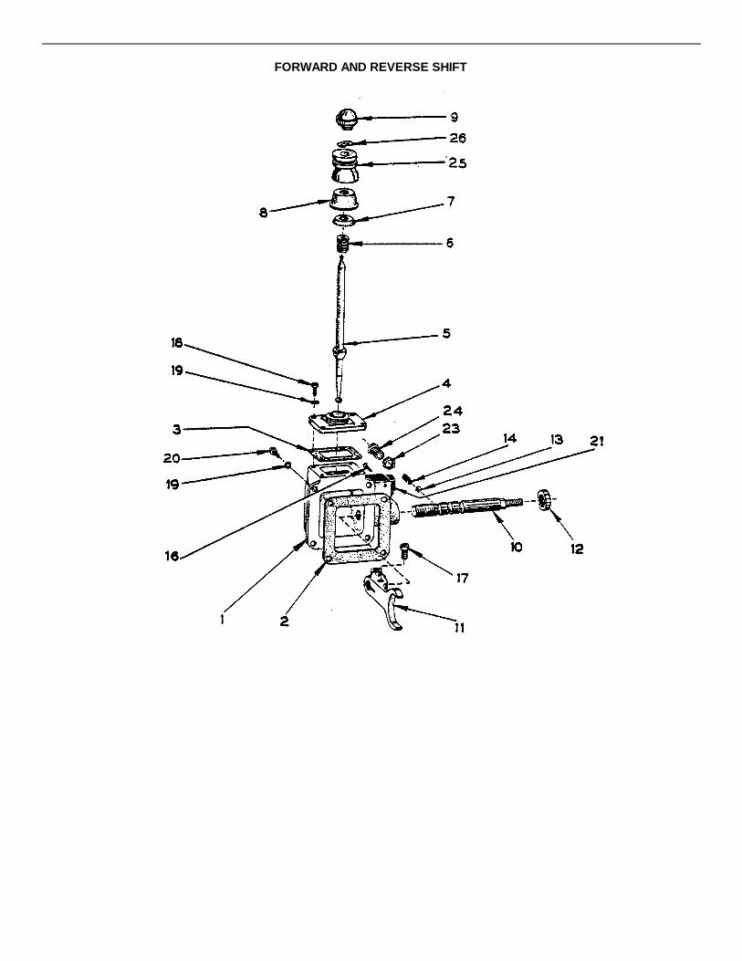
FORWARD AND REVERSE SHIFT

FORWARD AND REVERSE SHIFT
REF.NO. PART NUMBER DESCRIPTION QUANTITY
5036DD02-03 Forward and Reverse Shift - Complete 11 45775-255-06 Housing 12 45775-259-12 Gasket, Housing 13 45775-259-11 Gasket, Shifter Cover 14 45775-256-30 Cover, Shifter 15 45775-269-03 Shift Lever, Forward and Reverse 16 45775-270-01 Spring, Shift Shaft 17 45775-262-03 Washer, Shift Cap 18 45775-273-01 Cap, Shift Housing 19 45775-252-01 Ball, Shift Lever 110 45775-257-16 Shifter, Shaft 111 45775-271-06 Fork, Forward and Reverse 112 45200-184 Seal, Oil 113 45775-277-01 Ball 114 45775-270-04 Spring 116 45775-262-47 Capscrew, 1-1/2" Socket Head NC 417 7065-016 Capscrew, 1-1/2" x 1-3/4" Hex Head NF 118 7010-013 Capscrew, 3/8" x 1" Hex Head NC 419 7014-003 Lockwasher, 3/8" 820 7009-006 Capscrew, 3/8" x 1" Hex Head NF 421 46200-001-13 Micro-Switch 123 7017-052 Nut, 3/4" Jam NF 124 45775-260-03 Retainer, Spring 125 45775-282-01 Boot, Cover 126 45775-261-04 Clamp, Boot 1

SPICER UNIVERSAL JOINT
REF.NO. PART NUMBER DESCRIPTION QUANTITY
5036DF03 Spicer Universal Joint Assembly,Complete 1
1 45377-500-01 Flange Yoke 22 45377-500-02 Sleeve Yoke Assembly 13 45377-501-01 Dust Cap 14 45377-502-01 Steel Washer 15 45377-502-02 Cork Washer 16 45377-503-01 Shaft Sub-Assembly 17 45377-504-01 Journal & Bearing Kit 2
45377-505-01 Journal Cross Assembly 245377-506-01 Bearing Assembly 845377-507-01 Snap Ring 845377-508-01 Zerk Nipple 245377-509-01 Journal Gasket 8
Quantities shown are for One Assembly Only.

CLUTCH, TRANSFER CASE AND BRAKES

CLUTCH, TRANSFER CASE AND BRAKES
REF.NO. PART NUMBER DESCRIPTION QUANTITY
1 45775-009-04 See Transfer Case - Right Hand - This Section 12 45775-009-05 See Transfer Case - Left Hand - This Section 13 See Electrically Released Brake - This Section 24 See Electric Clutch - This Section 25 4430-007-01 Flange 26 7340-017 Bushing 27 5036DD51 Key 28 4430-006-01-02 Flange 29 7131-076 Setscrew, 3/81' x ½ i NC 410 Key - See Electric Clutch - This Section 211 45200-027 Seal, Oil 212 7166-011 Bearing 413 5036DD19 Spacer 214 5036DF06 Spacer 215 7010-022 Capscrew, ½ ”x 1;½ " NC 816 7012-027 Nut, ½ " Hex NC 8
7014-005 Lockwasher, ½ i" 817 4430-003-01 Flange 218 5036DD55 Chain 219 9700-055 Sprocket, Transfer Case - Standard 1
9700-054 Sprocket, Transfer Case - Slow Down 120 9700-056 Plate, Retaining 221 7009-014 Capscrew, ½ ” x 1 ½ ” NF 4
7014-005 Lockwasher, ½ " 422 (7018-050 Setscrew 8
7017-029 Nut, 5/8" Jam NC 823 (7010-048 Capscrew, 3/4" x 3" NC 16
7012-009 Lockwasher, 3/4" 1624 For BSF-420 Paver - See Two Speed Transmission,
Hydraulic Motor, Clutch and Drive Shaft -This Section
For BSF-400 Paver - See 24 Speed Transmission,Clutch and Drive Shaft - This Section
25 See Track Drive - Section 2
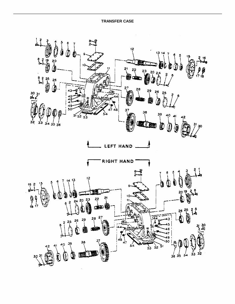
TRANSFER CASE
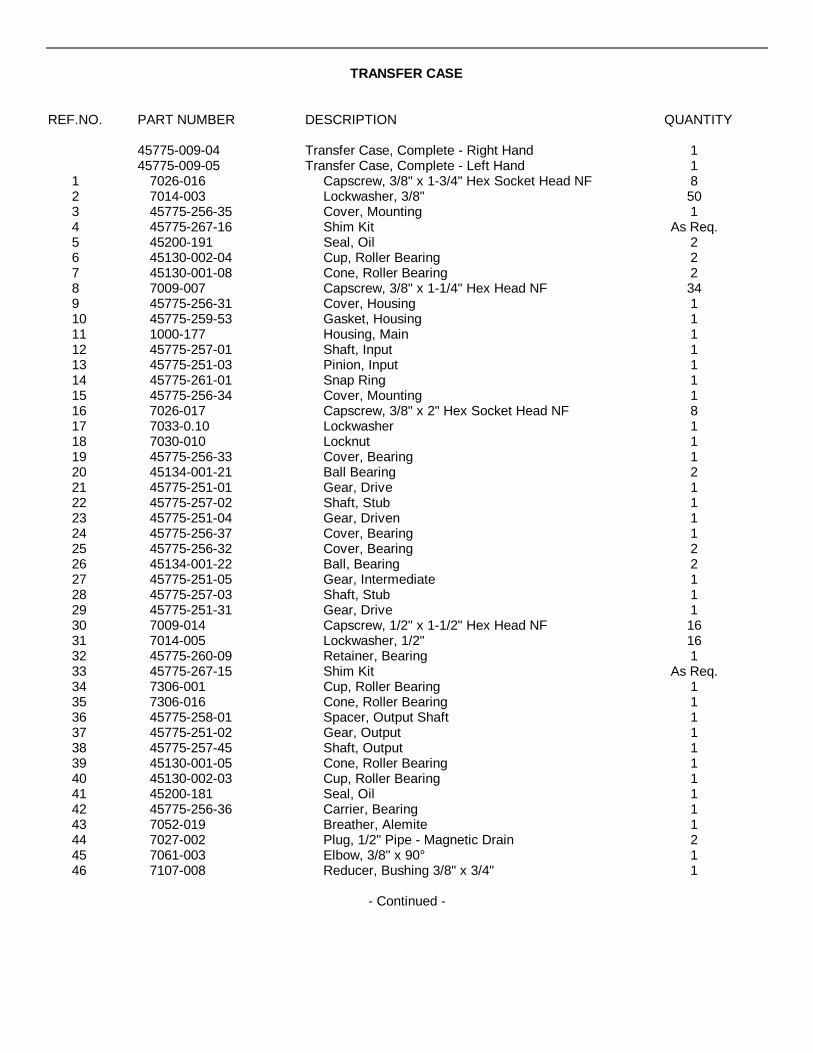
TRANSFER CASE
REF.NO. PART NUMBER DESCRIPTION QUANTITY
45775-009-04 Transfer Case, Complete - Right Hand 145775-009-05 Transfer Case, Complete - Left Hand 1
1 7026-016 Capscrew, 3/8" x 1-3/4" Hex Socket Head NF 82 7014-003 Lockwasher, 3/8" 503 45775-256-35 Cover, Mounting 14 45775-267-16 Shim Kit As Req.5 45200-191 Seal, Oil 26 45130-002-04 Cup, Roller Bearing 27 45130-001-08 Cone, Roller Bearing 28 7009-007 Capscrew, 3/8" x 1-1/4" Hex Head NF 349 45775-256-31 Cover, Housing 110 45775-259-53 Gasket, Housing 111 1000-177 Housing, Main 112 45775-257-01 Shaft, Input 113 45775-251-03 Pinion, Input 114 45775-261-01 Snap Ring 115 45775-256-34 Cover, Mounting 116 7026-017 Capscrew, 3/8" x 2" Hex Socket Head NF 817 7033-0.10 Lockwasher 118 7030-010 Locknut 119 45775-256-33 Cover, Bearing 120 45134-001-21 Ball Bearing 221 45775-251-01 Gear, Drive 122 45775-257-02 Shaft, Stub 123 45775-251-04 Gear, Driven 124 45775-256-37 Cover, Bearing 125 45775-256-32 Cover, Bearing 226 45134-001-22 Ball, Bearing 227 45775-251-05 Gear, Intermediate 128 45775-257-03 Shaft, Stub 129 45775-251-31 Gear, Drive 130 7009-014 Capscrew, 1/2" x 1-1/2" Hex Head NF 1631 7014-005 Lockwasher, 1/2" 1632 45775-260-09 Retainer, Bearing 133 45775-267-15 Shim Kit As Req.34 7306-001 Cup, Roller Bearing 135 7306-016 Cone, Roller Bearing 136 45775-258-01 Spacer, Output Shaft 137 45775-251-02 Gear, Output 138 45775-257-45 Shaft, Output 139 45130-001-05 Cone, Roller Bearing 140 45130-002-03 Cup, Roller Bearing 141 45200-181 Seal, Oil 142 45775-256-36 Carrier, Bearing 143 7052-019 Breather, Alemite 144 7027-002 Plug, 1/2" Pipe - Magnetic Drain 245 7061-003 Elbow, 3/8" x 90° 146 7107-008 Reducer, Bushing 3/8" x 3/4" 1
- Continued -
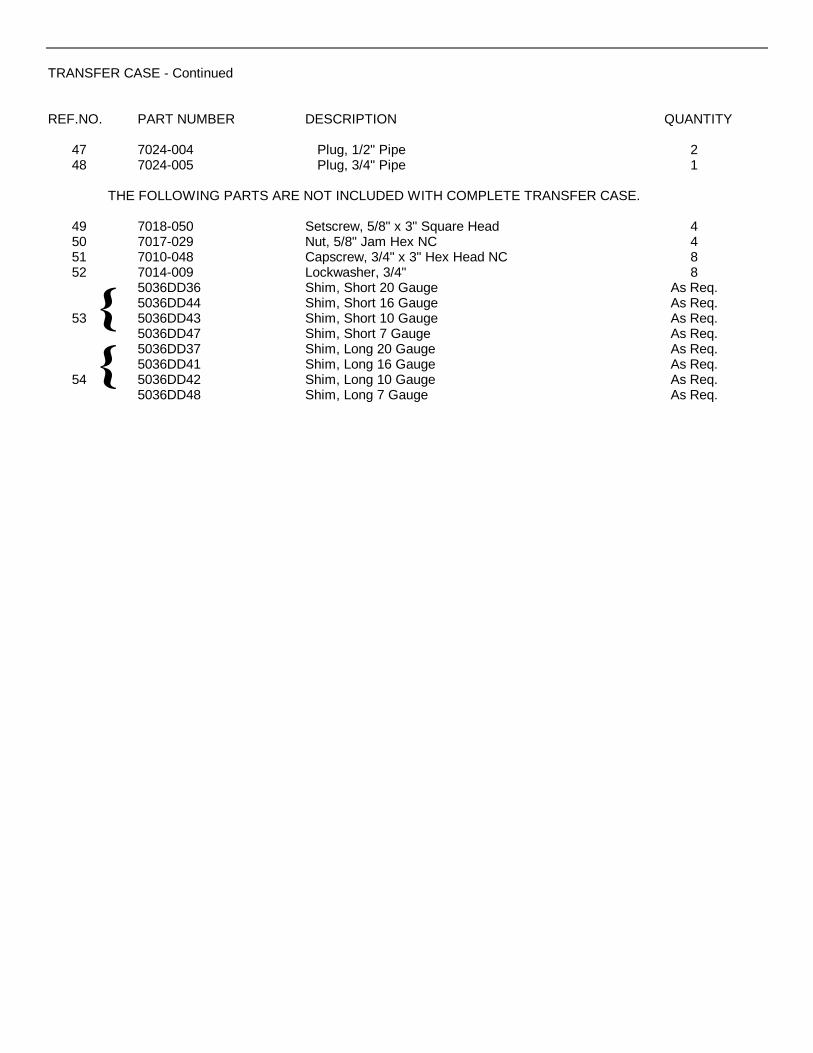
TRANSFER CASE - Continued
REF.NO. PART NUMBER DESCRIPTION QUANTITY
47 7024-004 Plug, 1/2" Pipe 248 7024-005 Plug, 3/4" Pipe 1
THE FOLLOWING PARTS ARE NOT INCLUDED WITH COMPLETE TRANSFER CASE.
49 7018-050 Setscrew, 5/8" x 3" Square Head 450 7017-029 Nut, 5/8" Jam Hex NC 451 7010-048 Capscrew, 3/4" x 3" Hex Head NC 852 7014-009 Lockwasher, 3/4" 8
5036DD36 Shim, Short 20 Gauge As Req.5036DD44 Shim, Short 16 Gauge As Req.
53 5036DD43 Shim, Short 10 Gauge As Req.5036DD47 Shim, Short 7 Gauge As Req.5036DD37 Shim, Long 20 Gauge As Req.5036DD41 Shim, Long 16 Gauge As Req.
54 5036DD42 Shim, Long 10 Gauge As Req.5036DD48 Shim, Long 7 Gauge As Req.
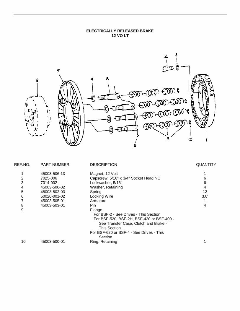
ELECTRICALLY RELEASED BRAKE12 VO LT
REF.NO. PART NUMBER DESCRIPTION QUANTITY
1 45003-506-13 Magnet, 12 Volt 12 7025-006 Capscrew, 5/16" x 3/4" Socket Head NC 63 7014-002 Lockwasher, 5/16" 64 45003-500-02 Washer, Retaining 45 45003-502-03 Spring 126 50020-001-02 Locking Wire 3.0'7 45003-505-01 Armature 18 45003-503-01 Pin 49 Flange
For BSF-2 - See Drives - This SectionFor BSF-520, BSF-2H, BSF-420 or BSF-400 -
See Transfer Case, Clutch and Brake -This Section
For BSF-620 or BSF-4 - See Drives - ThisSection
10 45003-500-01 Ring, Retaining 1

ELECTRIC CLUTCH - 12 VOLT
REF.NO. PART NUMBER DESCRIPTION QUANTITY
1 45003-504-02 Field Assembly, Inside Mounted 12 Volt 12 45551-263-01 Rotor 13 45552-258-01 Armature 14 45003-501-01 Hub, Rotor 15 7341-009 Bushing, Taperlock 2" Bore 16 7010-006 Capscrew, 5/16" x 3/4" 207 7014-002 Lockwasher, 5/16" 208 50360G02 Pin, Clutch Drive 49 45003-502-02 Spring, Follow Up 410 7264-037 Key, 1/2" x 1/2" x 2" Round End 1
NOTE: Quantities shown are for one clutch assembly only.
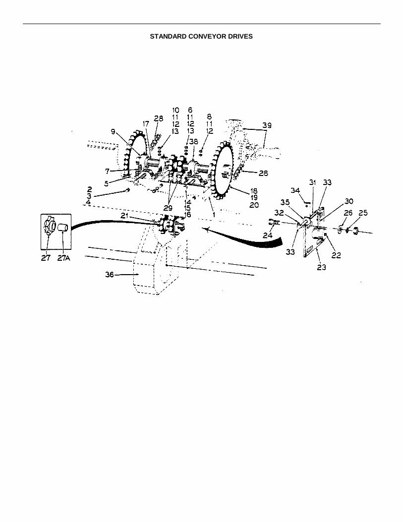
STANDARD CONVEYOR DRIVES

STANDARD CONVEYOR DRIVES
REF.NO. PART NUMBER DESCRIPTION QUANTITY
1 5036DD06 Frame 12 7010-031 Capscrew, 5/8" x 1¼" NC 53 7012-029 Nut, 5/8" Hex NC 54 7014-007 Lockwasher, 5/8" 55 5036DD07 Plate, Take-Up 26 7072-102 Bolt, Carriage ½ " x 1i½ " NC 87 1206B10 Lug, Adjusting 28 7445-001 Bolt, Plow #3 I-" x 1-3/4" NC 49 F0115PGA Pillow Block Bearing - 1-15/16" Bore - See Form #
1003 - This Section 410 7445-002 Bolt, Plow #3 2" x 2" NC 811 7012-027 Nut, ½ " Hex NC 2012 7014-005 Lockwasher, ½ " 2013 7014-020 Washer, ½ " Flat 1614 7153-027 Bolt, Adjusting 3/4" x 8½ " NC 215 7012-008 Nut, 3/4" Square NC 216 7017-030 Nut, 3/4" Jam NC 417 5036DD08 Shaft and Sprocket 218 1387A39E Sprocket, Standard 1
1387A30F Sprocket, Speed Up 119 40803-b03 Key, ½ " Square x 3" 220 7131-077 Setscrew, 3/8".x 5/8" NC 421 5036DD23 Shaft, Idler 122 7024-001 Plug, 1/8" Pipe 223 5036DD24 Plate 124 7010-020 Capscrew, ½ ” x 1" NC 825 7014-005 Lockwasher, l" 826 7014-020 Washer, ½ '" Flat 827 5036DD16 Sprocket, With Bushing 227A 7254-033 Bushing (Only) 228 5036DD38 Chain, #100 Roller Counter Drive 229 9701-132 Chain, #120 Roller Conveyor Drives 230 40500-002-00-01 Nipple, Pipe 1/8" x 2" 231 40500-005-08-01 Nipple, Pipe 1/8" x 5½ " 232 7051-002 Fitting, Alemite 1/8" @45° 233 7085-001 Elbow, 900 Pipe 1/8" 434 7000E23B Base, Tube Clamp 235 7014-018 Washer, 3/8" Flat 236 Main Frame - See Main Frame - Section 338 7051-001 Fitting, Hydraulic Straight 1/8" 439 See Transmission, Clutch and Drive Shaft -
This Section

ANTI-FRICTION BEARING ASSEMBLIES
REF.NO. PART NUMBER DESCRIPTION QUANTITY
PILLOW BLOCK TYPE - 1" BORE1 F0100PGA Bearing Assembly - Complete 12 F0100PG Bearing Housing 13 7041-004 Bearing and Collar 14 Variable Grease Fitting 15 7131-046 Socket Head Set Screw - 1/" x 1/4" Cup Point 1
PILLOW BLOCK TYPE - 1-3/16" BORE
1 F0103PGA Bearing Assembly - Complete 12 F0103PG Bearing Housing 13 7041-007 Bearing and Collar 1
Variable Grease Fitting 15 7131-046 Set Screw, 1/4"x1/4" Socket Head, Cup Point 1
PILLOW BLOCK TYPE - 1-3/8" BORE
1 F0106PGA Bearing Assembly - Complete 12 F107PG Bearing Housing 1
7041-010 Bearing and Collar 1Variable Grease Fitting 1
5 7131-074 Socket Head Set Screw - 3/8" x 3/8" Cup Point 1
PILLOW BLOCK TYPE - 1-7/16" BORE
1 F0107PGA Bearing Assembly - Complete 12 F0107PG Bearing Housing 13 7041-011 Bearing and Collar 14 Variable Grease Fitting 15 7131-074 Socket Head Set Screw - 3/8" x 3/8" Cup Point 1
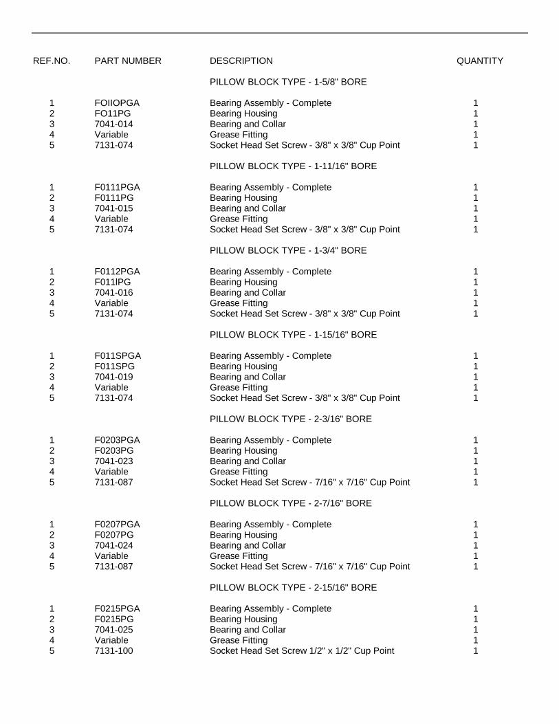
REF.NO. PART NUMBER DESCRIPTION QUANTITY
PILLOW BLOCK TYPE - 1-5/8" BORE
1 FOIIOPGA Bearing Assembly - Complete 12 FO11PG Bearing Housing 13 7041-014 Bearing and Collar 14 Variable Grease Fitting 15 7131-074 Socket Head Set Screw - 3/8" x 3/8" Cup Point 1
PILLOW BLOCK TYPE - 1-11/16" BORE
1 F0111PGA Bearing Assembly - Complete 12 F0111PG Bearing Housing 13 7041-015 Bearing and Collar 14 Variable Grease Fitting 15 7131-074 Socket Head Set Screw - 3/8" x 3/8" Cup Point 1
PILLOW BLOCK TYPE - 1-3/4" BORE
1 F0112PGA Bearing Assembly - Complete 12 F011lPG Bearing Housing 13 7041-016 Bearing and Collar 14 Variable Grease Fitting 15 7131-074 Socket Head Set Screw - 3/8" x 3/8" Cup Point 1
PILLOW BLOCK TYPE - 1-15/16" BORE
1 F011SPGA Bearing Assembly - Complete 12 F011SPG Bearing Housing 13 7041-019 Bearing and Collar 14 Variable Grease Fitting 15 7131-074 Socket Head Set Screw - 3/8" x 3/8" Cup Point 1
PILLOW BLOCK TYPE - 2-3/16" BORE
1 F0203PGA Bearing Assembly - Complete 12 F0203PG Bearing Housing 13 7041-023 Bearing and Collar 14 Variable Grease Fitting 15 7131-087 Socket Head Set Screw - 7/16" x 7/16" Cup Point 1
PILLOW BLOCK TYPE - 2-7/16" BORE
1 F0207PGA Bearing Assembly - Complete 12 F0207PG Bearing Housing 13 7041-024 Bearing and Collar 14 Variable Grease Fitting 15 7131-087 Socket Head Set Screw - 7/16" x 7/16" Cup Point 1
PILLOW BLOCK TYPE - 2-15/16" BORE
1 F0215PGA Bearing Assembly - Complete 12 F0215PG Bearing Housing 13 7041-025 Bearing and Collar 14 Variable Grease Fitting 15 7131-100 Socket Head Set Screw 1/2" x 1/2" Cup Point 1
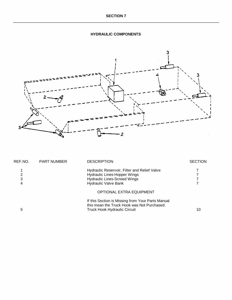
SECTION 7
HYDRAULIC COMPONENTS
REF.NO. PART NUMBER DESCRIPTION SECTION
1 Hydraulic Reservoir, Filter and Relief Valve 72 Hydraulic Lines-Hopper Wings 73 Hydraulic Lines-Screed Wings 74 Hydraulic Valve Bank 7
OPTIONAL EXTRA EQUIPMENT
If this Section is Missing from Your Parts Manualthis mean the Truck Hook was Not Purchased:
5 Truck Hook Hydraulic Circuit 10

HYDRAULIC RESERVOIR, FILTER & RELIEF VALVE

HYDRAULIC RESERVOIR, FILTER & RELIEF VALVE
REF.NO. PART NUMBER DESCRIPTION QUANTITY
1 5036QT05 Brace, Filter 12 40504-011-02-01 Nipple, 3/4" Pipe x 11-1/8" 13 40540-001-02-01 Nipple, 2" Pipe x 1-1/8" 14 40540-002-00-01 Nipple, ½ " Pipe x 2" 15 40500-001-08-01 Nipple, 1/8" Pipe x 1½ " 16 45080-510-21 Filter, Oil 17 45080-510-05 Filter, Oil Fill and Air Cap 18 45259-006-35 Valve, Relief - See Form - 11159 - This Section 19 45191-250-15 Fitting, 3/4" MP x 1" Hose 110 7430-002 Fitting, Str. ¼" MP x ¼ " 370 111 7430-007 Fitting, Str. ½ " MP x ½ " 370 212 7430-046 Fitting, Str. ¾ " MP x ½ " 370 113 45720-769-05 Reducer, Pipe ½ " x ¼" 114 7390-050 Tee, Pipe ½ " 115 7061-001 Elbow, 90º Street 1/8" Pipe 116 7061-005 Elbow, 90º Street 3/4" Pipe 317 7085-005 Elbow, 90º 3/4" Pipe 118 7084-001 Coupling, Pipe 1/8" 119 9704-650-60 Reservoir 120 5036QT03 Cover, Reservoir 121 5036QT04 Gasket, Reservoir 122 45080-510-20 Strainer, Oil 123 7060-004 Gauge, Oil Window 124 7027-003 Plug, Pipe Magnetic 125 7061-007 Elbow, 90º Street 1I" Pipe 126 7107-015 Bushing, Pipe 1¼" x 3/4" 127 45080-510-22 **Element, Filter 128 45080-001-21 **Gauge 1
**NOTE: Items 27 and 28 are furnished with Item # 6.
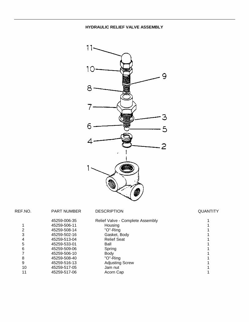
HYDRAULIC RELIEF VALVE ASSEMBLY
REF.NO. PART NUMBER DESCRIPTION QUANTITY
45259-006-35 Relief Valve - Complete Assembly 11 45259-506-11 Housing 12 45259-508-14 "O"-Ring 13 45259-502-16 Gasket, Body 14 45259-513-04 Relief Seat 15 45259-533-01 Ball 16 45259-509-06 Spring 17 45259-506-10 Body 18 45259-508-40 "O"-Ring 19 45259-516-13 Adjusting Screw 110 45259-517-05 Jam nut 111 45259-517-06 Acorn Cap 1

HYDRAULIC LINESHOPPER WINGS
REF.NO. PART NUMBER DESCRIPTION QUANTITY
1 7551-043-33-01 Hose - Complete 250035-043-00 Hose, 3/8" ID x 43" 245191-503-86 Swivel Fitting JIC 37º 245191-503-81 Swivel Fitting JIC 37º 2
2 7552-037-33 Hose - Complete 250036-037-00 Hose, '" ID 37" 245191-503-15 Swivel Fitting JIC 37º 4
3 7552-088-35 Hose - Complete 250036-088-00 Hose, ½ " ID x 88" 245191-503-15 Swivel Fitting JIC 37º 245191-503-47 90º Elbow With SAE 37º Nut 2
4 40540-102-00-01 Pipe, ½ " x 8'-6" 25 45720-770-10 Tee, ½ " Pipe 26 7430-022 Fitting, 90º 1/2" MP x ½ ” 37º 27 7430-007 Fitting, ½ " MP x ½ " 37º 48 7390-003 Elbow, 90º ½ " Pipe 29 See Hydraulic Line-Screed Lift - This Section10 See Reservoir - This Section11 See Valve Bank - This Section12 Pump - See Power Mounting - Section 613 Cylinder - See Hopper Wings - Section 3

HYDRAULIC LINESSCREED LIFT
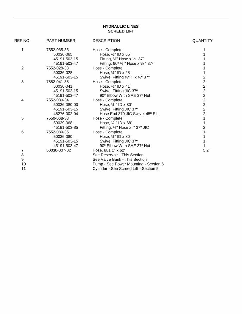
HYDRAULIC LINESSCREED LIFT
REF.NO. PART NUMBER DESCRIPTION QUANTITY
1 7552-065-35 Hose - Complete 150036-065 Hose, ½ " ID x 65" 145191-503-15 Fitting, ½ " Hose x ½ " 37º 145191-503-47 Fitting, 90º ½ " Hose x ½ " 37º 1
2 7552-028-33 Hose - Complete 150036-028 Hose, ½ " ID x 28" 145191-503-15 Swivel Fitting ½ " H x ½ " 37º 2
3 7552-041-35 Hose - Complete 250036-041 Hose, ½ " ID x 41" 245191-503-15 Swivel Fitting JIC 37º 245191-503-47 90º Elbow With SAE 37º Nut 2
4 7552-080-34 Hose - Complete 250036-080-00 Hose, ½ " ID x 80" 245191-503-15 Swivel Fitting JIC 37º 245276-002-04 Hose End 370 JIC Swivel 45º Ell. 2
5 7550-068-33 Hose - Complete 150039-068 Hose, ¼ " ID x 68" 145191-503-85 Fitting, ¼" Hose x i" 37º JIC 2
6 7552-080-35 Hose - Complete 150036-080 Hose, ½ " ID x 80" 145191-503-15 Swivel Fitting JIC 37º 145191-503-47 90º Elbow With SAE 37º Nut 1
7 50030-007-02 Hose, 881 1" x 62" 5.2’'8 See Reservoir - This Section9 See Valve Bank - This Section10 Pump - See Power Mounting - Section 611 Cylinder - See Screed Lift - Section 5
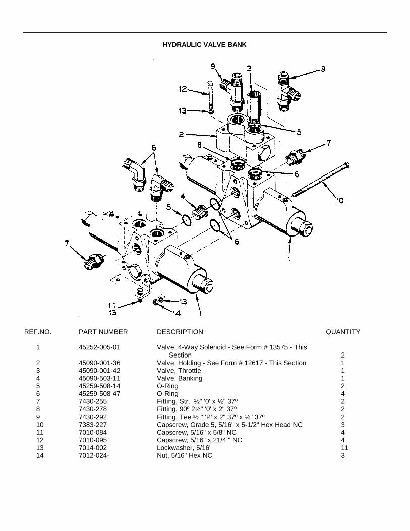
HYDRAULIC VALVE BANK
REF.NO. PART NUMBER DESCRIPTION QUANTITY
1 45252-005-01 Valve, 4-Way Solenoid - See Form # 13575 - ThisSection 2
2 45090-001-36 Valve, Holding - See Form # 12617 - This Section 13 45090-001-42 Valve, Throttle 14 45090-503-11 Valve, Banking 15 45259-508-14 O-Ring 26 45259-508-47 O-Ring 47 7430-255 Fitting, Str. ½ " '0' x ½ " 37º 28 7430-278 Fitting, 90º 2½ " '0' x 2" 37º 29 7430-292 Fitting, Tee ½ " 'P' x 2" 37º x ½ " 37º 210 7383-227 Capscrew, Grade 5, 5/16" x 5-1/2" Hex Head NC 311 7010-084 Capscrew, 5/16" x 5/8" NC 412 7010-095 Capscrew, 5/16" x 21/4 " NC 413 7014-002 Lockwasher, 5/16" 1114 7012-024- Nut, 5/16" Hex NC 3
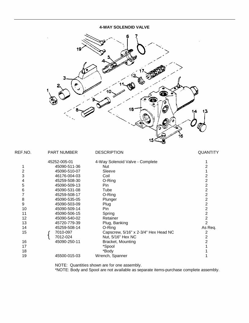
4-WAY SOLENOID VALVE
REF.NO. PART NUMBER DESCRIPTION QUANTITY
45252-005-01 4-Way Solenoid Valve - Complete 11 45090-511-36 Nut 22 45090-510-07 Sleeve 13 46176-004-03 Coil 24 45259-508-30 O-Ring 25 45090-509-13 Pin 26 45090-531-08 Tube 27 45259-508-17 O-Ring 28 45090-535-05 Plunger 29 45090-503-09 Plug 210 45090-509-14 Pin 211 45090-506-15 Spring 212 45090-540-02 Retainer 213 45720-779-39 Plug, Banking 214 45259-508-14 O-Ring As Req.15 7010-097 Capscrew, 5/16" x 2-3/4" Hex Head NC 2
7012-024 Nut, 5/16" Hex NC 216 45090-250-11 Bracket, Mounting 217 *Spool 118 *Body 119 45500-015-03 Wrench, Spanner 1
NOTE: Quantities shown are for one assembly.*NOTE: Body and Spool are not available as separate items-purchase complete assembly.
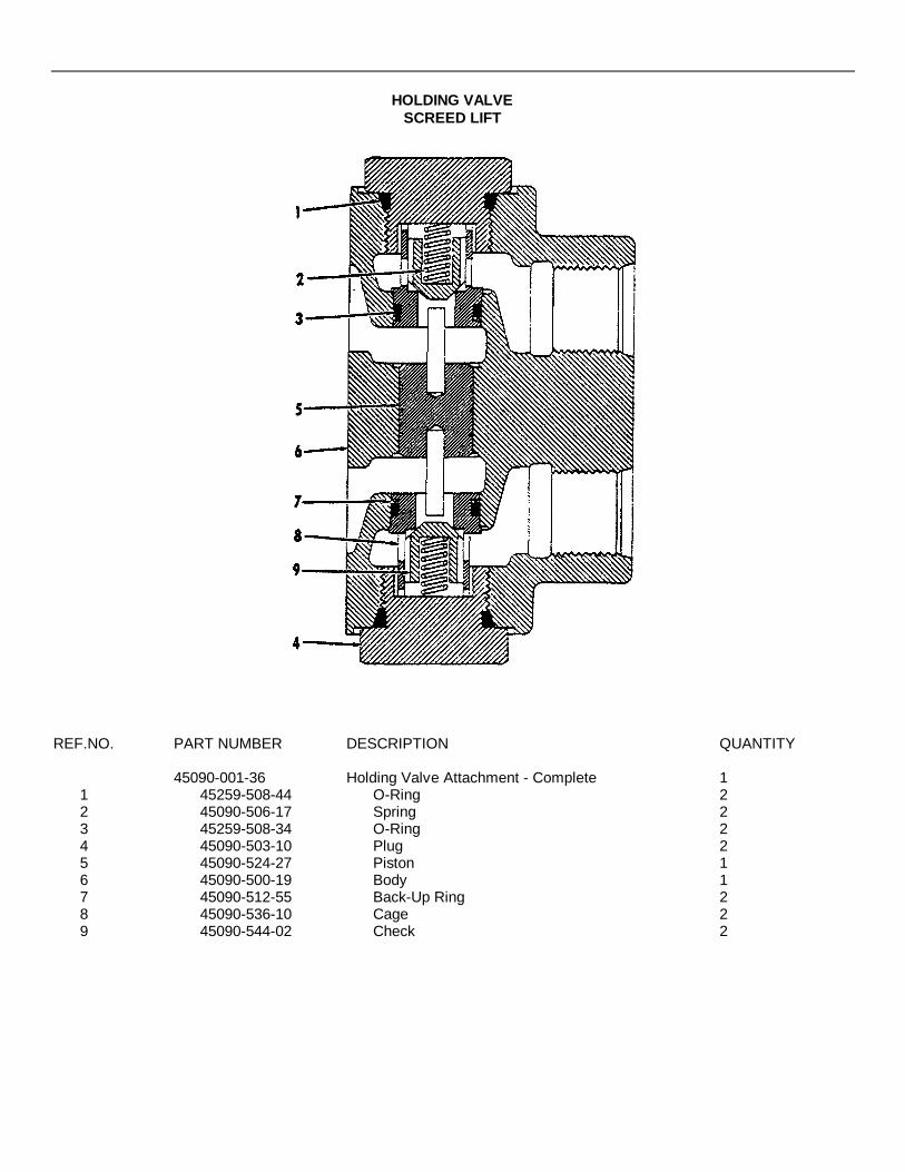
HOLDING VALVESCREED LIFT
REF.NO. PART NUMBER DESCRIPTION QUANTITY
45090-001-36 Holding Valve Attachment - Complete 11 45259-508-44 O-Ring 22 45090-506-17 Spring 23 45259-508-34 O-Ring 24 45090-503-10 Plug 25 45090-524-27 Piston 16 45090-500-19 Body 17 45090-512-55 Back-Up Ring 28 45090-536-10 Cage 29 45090-544-02 Check 2

SECTION 8
BASE ELECTRIC PARTS
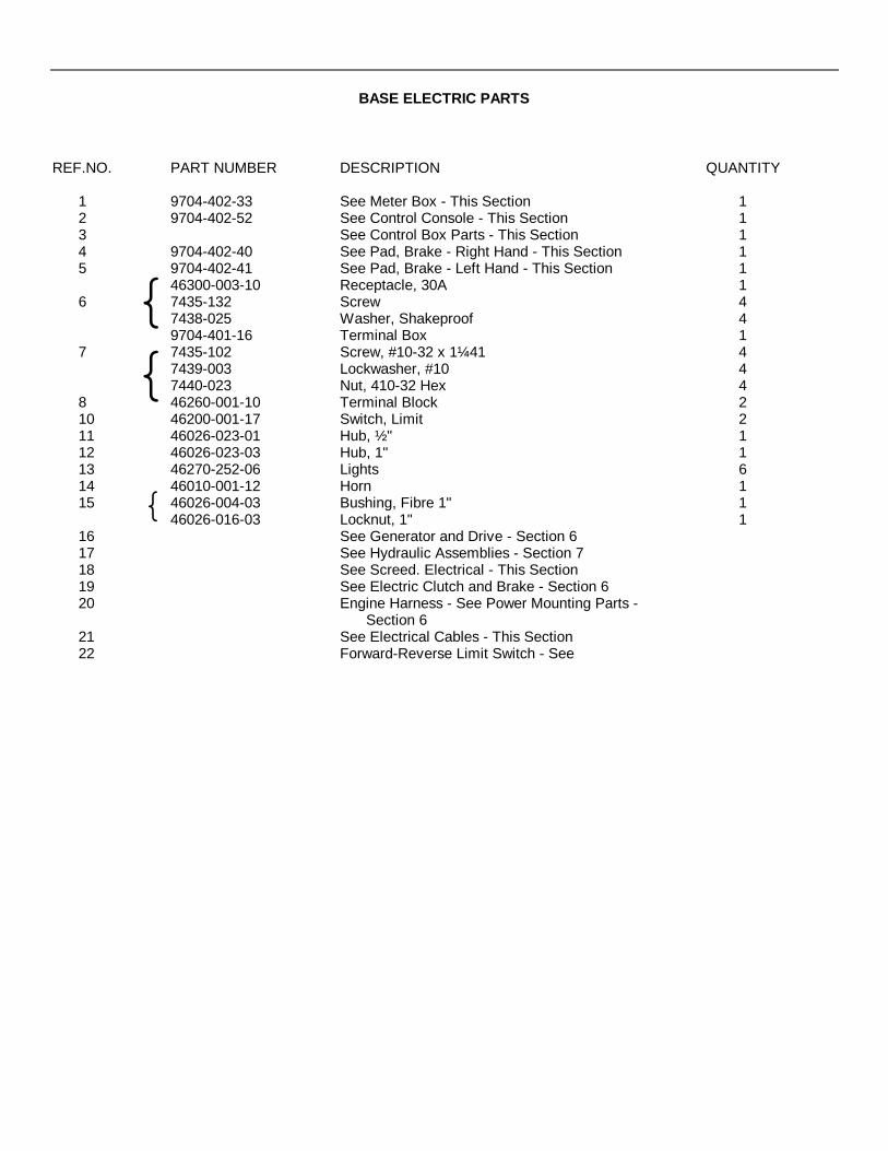
BASE ELECTRIC PARTS
REF.NO. PART NUMBER DESCRIPTION QUANTITY
1 9704-402-33 See Meter Box - This Section 12 9704-402-52 See Control Console - This Section 13 See Control Box Parts - This Section 14 9704-402-40 See Pad, Brake - Right Hand - This Section 15 9704-402-41 See Pad, Brake - Left Hand - This Section 1
46300-003-10 Receptacle, 30A 16 7435-132 Screw 4
7438-025 Washer, Shakeproof 49704-401-16 Terminal Box 1
7 7435-102 Screw, #10-32 x 1¼41 47439-003 Lockwasher, #10 47440-023 Nut, 410-32 Hex 4
8 46260-001-10 Terminal Block 210 46200-001-17 Switch, Limit 211 46026-023-01 Hub, ½ " 112 46026-023-03 Hub, 1" 113 46270-252-06 Lights 614 46010-001-12 Horn 115 46026-004-03 Bushing, Fibre 1" 1
46026-016-03 Locknut, 1" 116 See Generator and Drive - Section 617 See Hydraulic Assemblies - Section 718 See Screed. Electrical - This Section19 See Electric Clutch and Brake - Section 620 Engine Harness - See Power Mounting Parts -
Section 621 See Electrical Cables - This Section22 Forward-Reverse Limit Switch - See
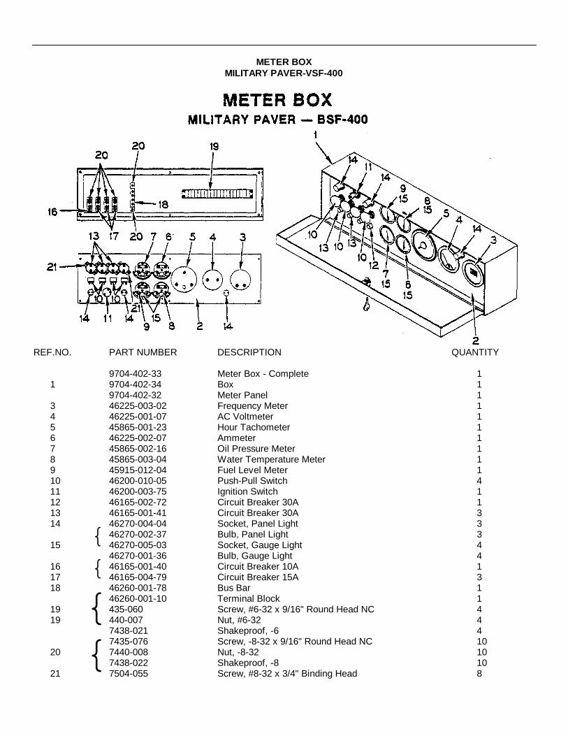
METER BOXMILITARY PAVER-VSF-400
REF.NO. PART NUMBER DESCRIPTION QUANTITY
9704-402-33 Meter Box - Complete 11 9704-402-34 Box 1
9704-402-32 Meter Panel 13 46225-003-02 Frequency Meter 14 46225-001-07 AC Voltmeter 15 45865-001-23 Hour Tachometer 16 46225-002-07 Ammeter 17 45865-002-16 Oil Pressure Meter 18 45865-003-04 Water Temperature Meter 19 45915-012-04 Fuel Level Meter 110 46200-010-05 Push-Pull Switch 411 46200-003-75 Ignition Switch 112 46165-002-72 Circuit Breaker 30A 113 46165-001-41 Circuit Breaker 30A 314 46270-004-04 Socket, Panel Light 3
46270-002-37 Bulb, Panel Light 315 46270-005-03 Socket, Gauge Light 4
46270-001-36 Bulb, Gauge Light 416 46165-001-40 Circuit Breaker 10A 117 46165-004-79 Circuit Breaker 15A 318 46260-001-78 Bus Bar 1
46260-001-10 Terminal Block 119 435-060 Screw, #6-32 x 9/16" Round Head NC 419 440-007 Nut, #6-32 4
7438-021 Shakeproof, -6 47435-076 Screw, -8-32 x 9/16" Round Head NC 10
20 7440-008 Nut, -8-32 107438-022 Shakeproof, -8 10
21 7504-055 Screw, #8-32 x 3/4" Binding Head 8

CONTROL CONSOLE

CONTROL CONSOLE
REF.NO. PART NUMBER DESCRIPTION QUANTITY
9704-402-52 Control Console - Complete With Cover 11 5036JJC12 Cover 12 9704-401-63 Box, Console 13 46200-009-06 Switch 14 46200-009-08 Switch 35 46200-009-21 Switch 36 46200-009-11 Switch 17 46200-009-18 Switch 1
46200-009-08 Switch 28 46955-001-35 Diode9 5036JG09-01 Support, Console 110 5036JJC04 Yoke, Console Mount 111 7014-017 Washer, 5/16" Flat 412 7056-026 Nut, 5/16" Wing 213 4418-296 Instruction Decal 114 9704-402-51 Cable, Control Console to Rear Junction Box 115 46026-016-03 Locknut 1
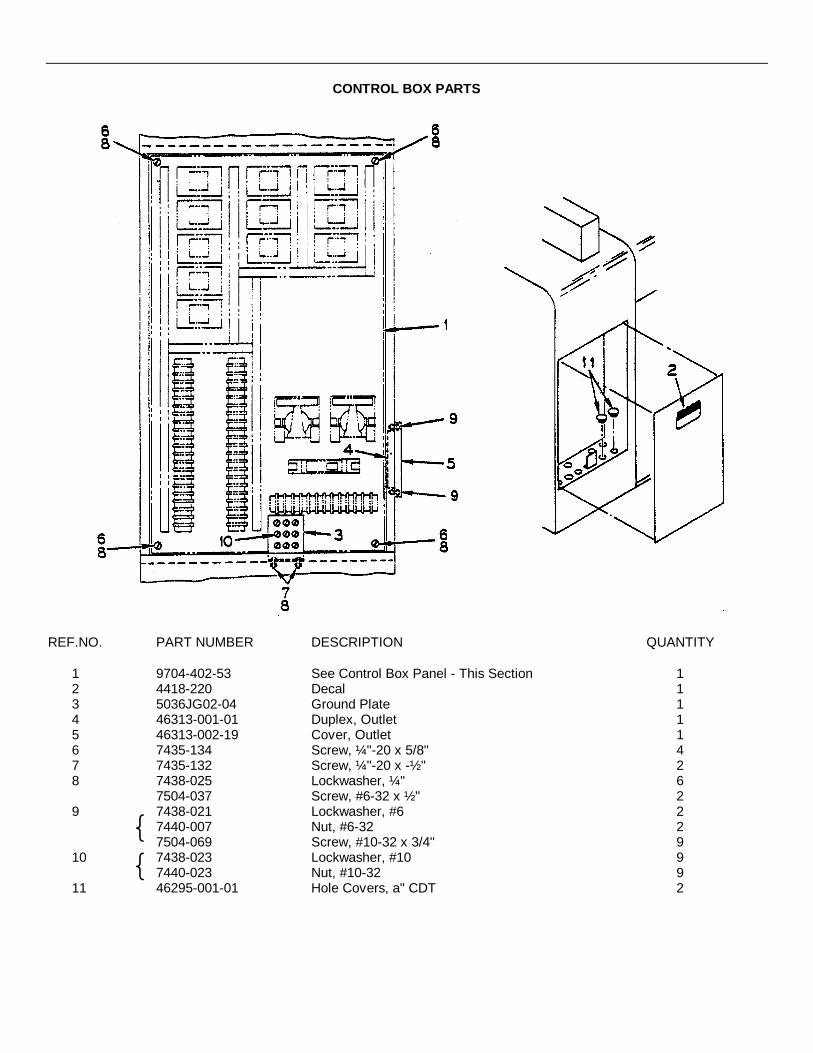
CONTROL BOX PARTS
REF.NO. PART NUMBER DESCRIPTION QUANTITY
1 9704-402-53 See Control Box Panel - This Section 12 4418-220 Decal 13 5036JG02-04 Ground Plate 14 46313-001-01 Duplex, Outlet 15 46313-002-19 Cover, Outlet 16 7435-134 Screw, ¼"-20 x 5/8" 47 7435-132 Screw, ¼"-20 x -½ " 28 7438-025 Lockwasher, ¼" 6
7504-037 Screw, #6-32 x ½ " 29 7438-021 Lockwasher, #6 2
7440-007 Nut, #6-32 27504-069 Screw, #10-32 x 3/4" 9
10 7438-023 Lockwasher, #10 97440-023 Nut, #10-32 9
11 46295-001-01 Hole Covers, a" CDT 2

CONTROL BOX PANEL

CONTROL BOX PANEL
REF.NO. PART NUMBER DESCRIPTION QUANTITY
9704-402-53 Panel - Complete 11 9704-401-05 Panel, Mounting 12 46325-002-16 Relay 23 46325-001-52 Relay 94 9800-019 Module, Bleeder 25 46960-002-54 Resistor 86 46955-001-35 Diodes 87 46165-002-93 Break, 30A 18 46260-001-10 Terminal Block 29 46260-001-04 Terminal Block 110 46015-001-13 Socket, Octal 1111 56000-003-01 Panduit, 1/2" x 1-1/4" 6.0’12 45345-001-02 Tape, Double-Sided 6.0’13 7504-052 Screw, #8-32 x 1/2" 6
438-022 Lockwasher, #8 67504-037 Screw, #6-32 x 1/2" 34
14 438-021 Lockwasher, #6 34
Not Shown
15 9704-402-55 Control Box Wire Harness - Complete 1
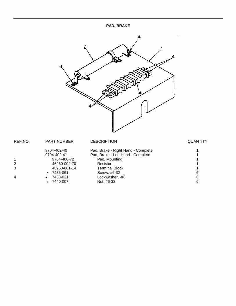
PAD, BRAKE
REF.NO. PART NUMBER DESCRIPTION QUANTITY
9704-402-40 Pad, Brake - Right Hand - Complete 19704-402-41 Pad, Brake - Left Hand - Complete 1
1 9704-400-72 Pad, Mounting 12 46960-002-70 Resistor 13 46260-001-14 Terminal Block 1
7435-061 Screw, #6-32 64 7438-021 Lockwasher, -#6 6
7440-007 Nut, #6-32 6
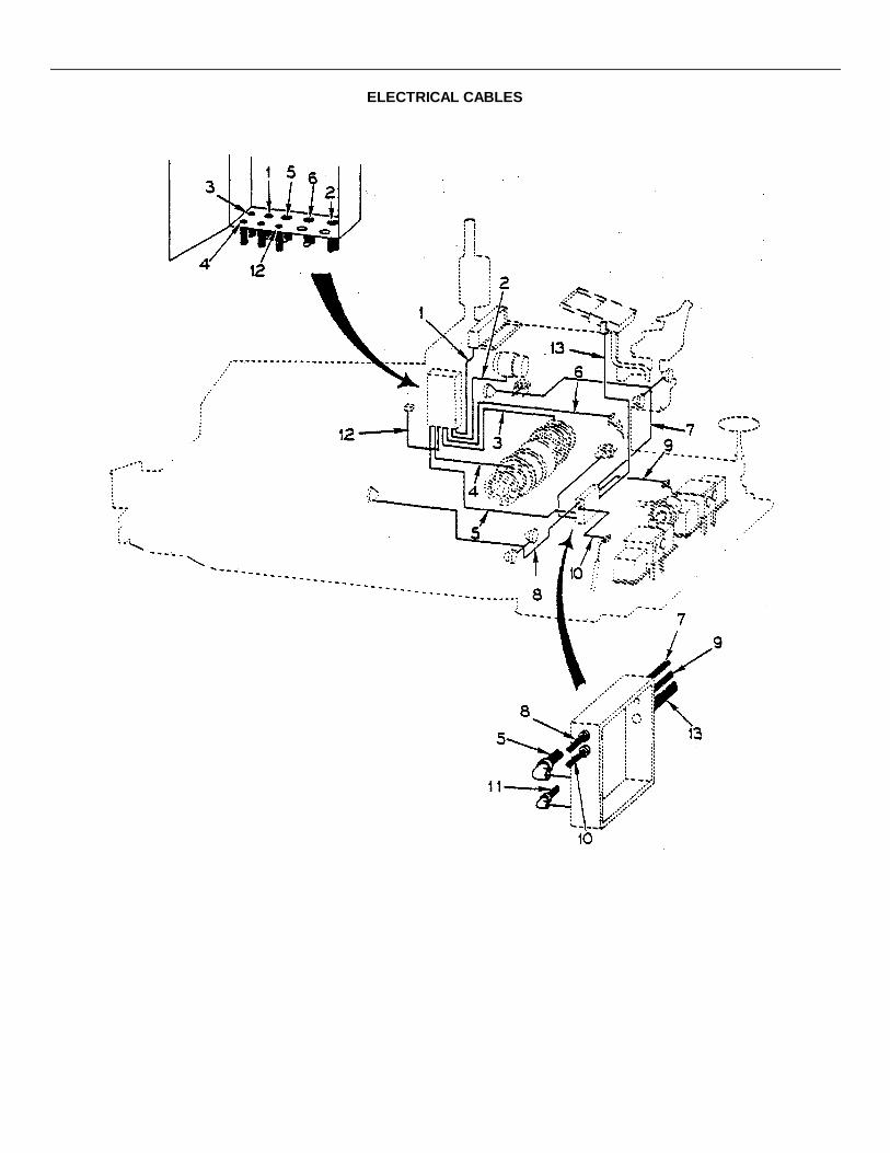
ELECTRICAL CABLES

ELECTRICAL CABLES
REF.NO. PART NUMBER DESCRIPTION QUANTITY
1 9704-402-54 Conduit, Meter Box to Control Box 12 9704-400-84 Conduit, A.C. Generator to Control Box 13 9704-402-42 Cable, Control Box to Right Hand Brake 14 9704-402-43 Cable, Control Box to Left Hand Brake 15 9704-402-49 Cable, Control Box to Rear Junction Box 16 9704-400-78 Cable, Control Box to Screed Receptacle 17 9704-402-46 Cable, Right Hand Lights to Junction Box 18 9704-402-47 Cable, Left Hand Lights to Junction Box 19 9704-402-44 Cable, Limit Switch to Junction Box - Right Hand 110 9704-402-45 Cable, Limit Switch to Junction Box - Left Hand 111 9704-402-48 Cable, Junction Box to Solenoid Bank 112 9704-402-50 Cable, Control Box to Forward-Reverse Limit
Switch 113 See Control Console - Cable-Console to Junction
Box - This Section 1
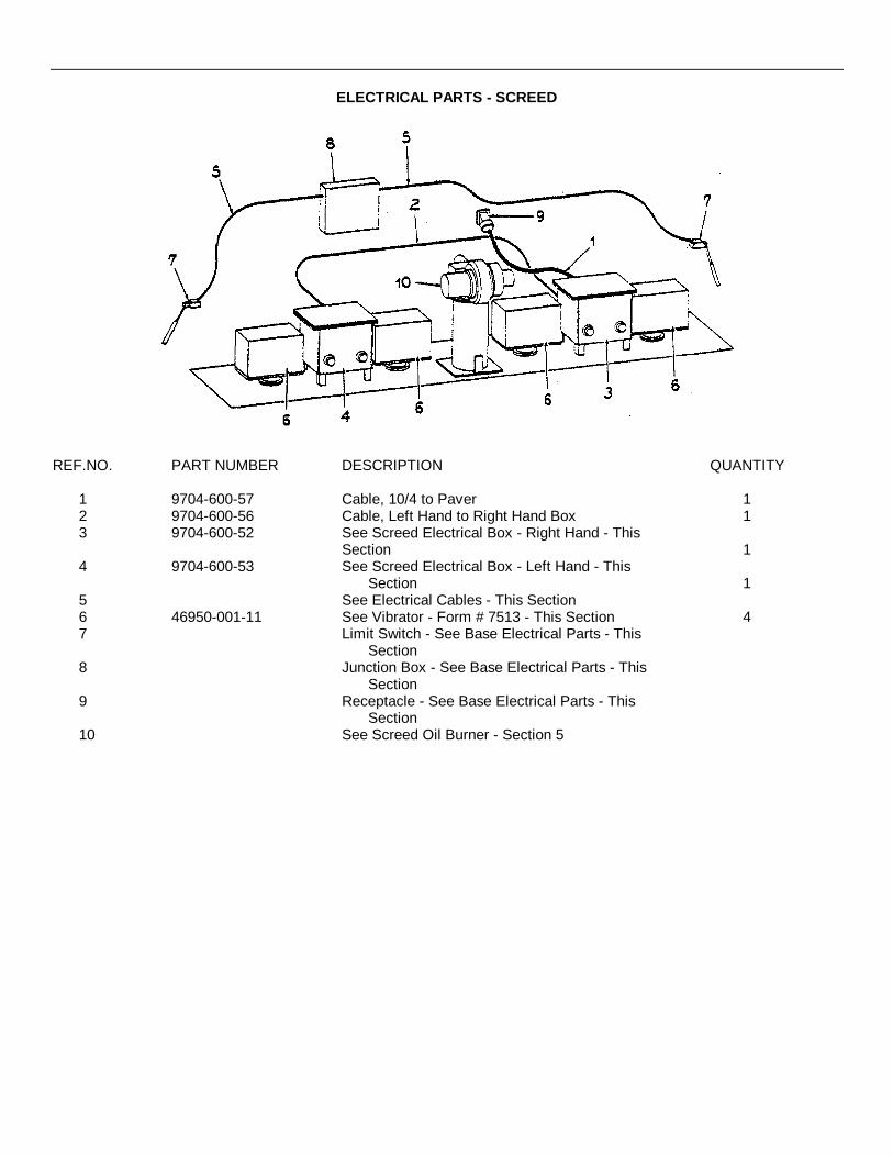
ELECTRICAL PARTS - SCREED
REF.NO. PART NUMBER DESCRIPTION QUANTITY
1 9704-600-57 Cable, 10/4 to Paver 12 9704-600-56 Cable, Left Hand to Right Hand Box 13 9704-600-52 See Screed Electrical Box - Right Hand - This
Section 14 9704-600-53 See Screed Electrical Box - Left Hand - This
Section 15 See Electrical Cables - This Section6 46950-001-11 See Vibrator - Form # 7513 - This Section 47 Limit Switch - See Base Electrical Parts - This
Section8 Junction Box - See Base Electrical Parts - This
Section9 Receptacle - See Base Electrical Parts - This
Section10 See Screed Oil Burner - Section 5

SCREED ELECTRICAL BOX
REF.NO. PART NUMBER DESCRIPTION QUANTITY
1 9704-600-51 Box 22 46245-251-11 Auto-Transformer 23 5036PDG02 Washer, Rubber 24 46260-001-05 Terminal Block 1S 9704-600-06 Pulsator - See Form # 14356 - This Section 16 9800-643 Plate 17 9800-738 Plate 28 9800-626 Cover 1

PULSATOR
REF.NO. PART NUMBER DESCRIPTION QUANTITY
9704-600-06 Pulsator - Complete 11 46960-002-65 Resistor 12 46960-002-30 Resistor 23 46960-002-63 Resistor4 46960-002-47 Resistor 15 46960-002-64 Resistor 26 46180-001-18 Capacitor 27 46180-001-22 Capacitor8 46955-002-01 Transistor 39 46955-002-07 Transistor 110 46955-001-37 Diode11 46955-003-02 Heat Sink
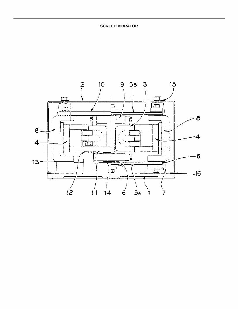
SCREED VIBRATOR

SCREED VIBRATOR
REF.NO. PART NUMBER DESCRIPTION *QUANTITY
46950-001-11 Vibrator - Complete1 46950-520-01 Base Casting 12 46950-505-03 Cover 13 46950-510-02 Armature Assembly 24 46950-521-01 E-Frame Assembly 25 Spring
46950-501-05 (a) Bottom 146950-501-06 (b) Top 1
6 46950-504-02 Spacer, Spring 147 46950-506-02 Clamp, Spring 68 46950-522-01 Support, End 29 46950-523-01 Hammer Assembly 110 46950-524-01 Rod, Tie 211 46950-525-01 Bar, Strike 212 46950-518-02 Shim, Strike Bar As Req.13 46950-518-03 Shim, End Support As Req.14 46950-526-01 Pads, Impact Set of 415 46950-513-10 Grommet, Capscrew - Cover 416 41733-003-03 Seal, Neoprene 4.6'
*NOTE: Quantities Shown are for One vibrator Only. When Ordering always give Eriez ModelNumber and Serial Number.

PART VII
SUPPLEIMNTAL OPERATING, MAINTENANCE, AND REPAIR PAIRTS INSTRUCTIONS
FOR
PAVING MACHINE, BITUMINOUS MATERIAL, CRAWLER-MOUNTEDDIESEL-ENGINE-DRIVEN
TABLE OF CONTENTS
Section I GENERAL Paragraph PagePurpose 1-1 1Scope 1-2 1Description 1-3 1Operational Concept 1-4 1Procurement Status 1-5 1Equipment Publications 1-6 2Personnel and Training 1-7 2Logistics Assistance 1-8 2Warranty 1-9 3Reporting 1-10 3
Section II MAINTENANCEMaintenance Concept 2-1 4Maintenance Allocation Chart 2-2 4Modifications 2-3 4Equipment Improvement Recommendations 2-4 5Equipment Readiness Reporting 2-5 5Maintenance Expenditure Limits 2-6 5Shipment and Storage 2-7 5Destruction to Prevent Enemy Use 2-8 5Fire Protection 2-9 5Basic Issue Items List 2-10 5Maintenance and Operating Supply List 2-11 5Special Tools and Equipment 2-12 5Maintenance Forms and Records 2-13 5
Section III REPAIR PARTS SUPPLY
General 3-1 6Prescribed Load List 3-2 6Authorized Stockage List 3-3 6Requisitioning Repair Parts 3-4 7Submitting Requisitions 3-5 7
i

TABLE OF CONTENTS (Continued)
APPENDIXES PAGE
A Equipment Publications A-1B Warranty Guidelines B-1C Maintenance Allocation Chart C-1D Modification Procedure D-1E Basic Issue Items List E-1F Items Troop Installed Or Authorized List F-1G Prescribed Load List/Authorized Stockage List G-1H Sample Format, DA Form 2765, Part Number Request H-1I Sample Format, MILSTRIP Request (NSN) I-1J Sample Format, MILSTRIP Request (NON-NSN) J-1K Sample Format, MILSTRIP Request (NON-NSN Manual) K-1L Cross Reference Part Number List L-1M Maintenance And Operating Supply List M-1N Preventive Maintenance Checks And Services
Operator/Crew PMCSOrganizational PMCS N-1
O Cleaning And Lubricating Paver O-1P Lubrication Detail P-1Q Asphalt Paver Lubrication Chart Q-1R Index For Engine Repair Parts R-1
ii

SECTION I
GENERAL
1-1. Purpose. To provide User and Support personnel supplemental maintenance and repair parts instructions thathave special application for the Paving Machine - Model BSF-400.
1-2. Scope. This publication applies to Department of the Army Units, Organizations and Activities that use and/orsupport the Paving Machine, Bituminous Material, Crawler - Mounted.
1-3. Description. The Paving Machine, Bituminous Material, Crawler Mounted is designed to lay a uniform high densitymat of asphalt material, on highways, roadways, airport runways, parking lots, and driveways. It is capable of performingjobs having strict control specifications and high production requirements.
The paver will level and compact asphalt material up to 10 inches in depth with mat widths varying from 6 to 20 feet.Mat depth and width are accomplished by adjustment of feed controls and by arrangement and adjustment of thefinishing and compacting device called the "screed."
1-4. Operational Concept. The uniformly mixed hot asphalt material is dumped by truck onto the hopper of the paverat a rate suitable for spreading. The paver contacts the rear wheels of the truck and pushes the vehicle ahead as thepaving progresses. The hot material is metered by two separate slat conveyors to the two spreading screws at the rearof the tractor and ahead of the screed where the feed of material may be manually or automatically regulated for properdistribution. The screed rides up on the asphalt to the degree set on the adjustable controls and varies the thickness andcontour of the mat deposited beneath it. The screed unit is equipped with electric vibrators which assist in the initialcompaction and smoothing of the high density mat. Final compaction is accomplished by separate rolling equipment.
Numerous cut-off and leveling attachments meet the need for varying width and contour requirements.
The screed is equipped with an oil fired heater which is operated prior to paving, in order to bring the screed temperatureup to the temperature of the asphalt so that no sticking or dragging will occur.
Raising and lowering of the full floating screed for paving or travel is done hydraulically by toggle switch control.
1-5. Procurement Status. The procurement contract number is IDA 700-77- C-8481 and was awarded on 15 August1977. Additional Pavers were procured under Contract Number DAAE07-79-C-5795, dtd 29 Jun 79.
1

1-6. Equipment Publications .
a. Initially two sets of the manufacturer's commercial publications will be overpacked and shipped with each paver(reference Appendix a).
b. Additional commercial manuals may be obtained by requisitioning from Defense Construction Supply Center(DCSC). Requisitions to DCSC should be prepared in the same manner as for part numbered repair parts, using theFederal Supply Code for manufacturer's FSCM and manual numbers listed in Appendix A. If DD Form 1348-6 is used,mail it direct to Commander, DCSC, ATTN: DCSC-OSR, Columbus, OH 43215.
c. If additional assistance is required, contact the address in paragraph 1-10 of this publication.
1-7. Personnel and Training.
a. MOS Requirements:
(1) Operator: 62H20, Concrete/Asphalt Equipment Operator.(2) Organizational Maintenance: 62B20, Construction Equipment Repairman.(3) Direct and General Support Maintenance: 62B30, Construction Equipment Repairman; 63G20, Fuel and
Electrical Systems Repairman, 44B20 Metal Body Repairman.
b. New Equipment Training: New Equipment Training Teams (NETTs) are available to major field commands.Requests for NETTs should be forwarded to Commander, US Army Tank-Automotive Materiel Readiness Command(TARCOM), ATTN: DRSTA-MLT, Warren, MI 48090. Training teams should be requested only when trained personnelare not available in the command to operator and/or maintain the paving machine.
1-8. Logistics Assistance.
a. Tank-Automotive Command Field Maintenance Technicians (FMTs) stationed at CONUS and OCONUSinstallations will be fully qualified and available to furnish on-site training and or assistance concurrent with receipt of thepaving machine.
b. Assistance can be obtained by contacting the Logistics Assistance Office listed in Appendix B of AR 700-4.
2

1-9. Warranty. The paving machine contractor warrants the products furnished under this contract according to theterms and conditions described in the equipment publications and Appendix B of this publication. All warrantiesfurnished to the paving machine contractor by subcontractors of assemblies or components utilized in the manufacture ofthe end item will be extended to the Government. See Appendix B for warranty guidelines.
1-10. Reporting. You can improve this publication by recommending improvements, using DA Form 2028(Recommend Changes to Publications and Blank Forms) and mail direct to Commander, US Army Tank-AutomotiveMateriel Readiness Command, ATTN: DRSTA-MBA(S), Warren, MI 48090.
3
SECTION II
MAINTENANCE
2-1. Maintenance Concept. The paving machine will not require any new or special maintenance considerations. Allmaintenance functions can be accomplished within the current maintenance concepts established for constructionequipment.
a. Operator/Crew Maintenance: Operator and crew maintenance is limited to daily preventive maintenance checks andservices.
b Organizational Maintenance: Organizational maintenance consists of scheduled preventive maintenance services,minor repairs and adjustments.
c. Direct Support Maintenance: Direct support maintenance consists of repairs on-site or in a direct support unit's shops.Repairs are accomplished with a minimum of tools and test equipment; the assemblies and end items thus repaired arereturned to their users.
d. General Support Maintenance: General support maintenance overhauls selected assemblies and repairs itemsdesignated by the area support command for return to stock.
e. Depot Maintenance: Depot maintenance overhauls end items and selected major assemblies when they are requiredto satisfy overall Army requirements. Overhaul of the end item may also be performed by contract with themanufacturer.
2-2. Maintenance Allocation Chart. Maintenance will be performed as necessary by the category indicated in theMaintenance Allocation Chart (MAC) (Appendix C) to retain or restore serviceability. All authorized maintenance withinthe capability of a using organization will be accomplished before referring the item to support maintenance. Highercategories will perform the maintenance functions of lower categories when required or directed by the appropriateCommanders. Using and support units may exceed their authorized scope and functions in the MAC when approval isgranted by the next higher support maintenance Commander.
2-3. Modifications . Modifications will be accomplished by the end item manufacturer after TARCOM approves the fieldcampaign or modification plan. See Appendix D.
4
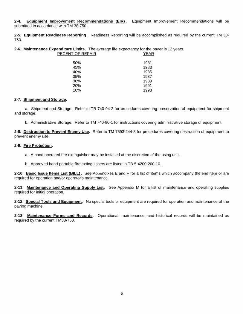
2-4. Equipment Improvement Recommendations (EIR) . Equipment Improvement Recommendations will besubmitted in accordance with TM 38-750.
2-5. Equipment Readiness Reporting. Readiness Reporting will be accomplished as required by the current TM 38-750.
2-6. Maintenance Expenditure Limits. The average life expectancy for the paver is 12 years.PECENT OF REPAIR YEAR
50% 198145% 198340% 198535% 198730% 198920% 199110% 1993
2-7. Shipment and Storage.
a. Shipment and Storage. Refer to TB 740-94-2 for procedures covering preservation of equipment for shipmentand storage.
b. Administrative Storage. Refer to TM 740-90-1 for instructions covering administrative storage of equipment.
2-8. Destruction to Prevent Enemy Use. Refer to TM 7593-244-3 for procedures covering destruction of equipment toprevent enemy use.
2-9. Fire Protection.
a. A hand operated fire extinguisher may be installed at the discretion of the using unit.
b. Approved hand-portable fire extinguishers are listed in TB 5-4200-200-10.
2-10. Basic Issue Items List (BILL) . See Appendixes E and F for a list of items which accompany the end item or arerequired for operation and/or operator's maintenance.
2-11. Maintenance and Operating Supply List . See Appendix M for a list of maintenance and operating suppliesrequired for initial operation.
2-12. Special Tools and Equipment . No special tools or equipment are required for operation and maintenance of thepaving machine.
2-13. Maintenance Forms and Records. Operational, maintenance, and historical records will be maintained asrequired by the current TM38-750.
5

SECTION III
REPAIR PARTS SUPPLY
3-1. General.
a. The basic policies and procedures in AR 710-2, AR 725-50 and DA CIR70)-27 are applicable to repair partsmanagement for construction equipment.
b. Manufacturer's parts manuals are furnished with paver instead of Department of the Army Repair Parts andSpecial Tool List (RPSTL).
c. National Stock Number (NSNs) are initially assigned only to PLL/ASL parts and major assemblies, i.e., engines,transmissions, etc. Additional NSNs are assigned by the supply support activities as demands warrant.
d. Automated Processing (AUTODIN) of Federal Supply Code Manufacturer (FSCM) part number requisitions,without edit fair matching NSNs and exception data, is authorized.
e. Proper use of project codes and weapon systems designator codes on parts requisitions is essential.
f. Repair parts are available from commercial sources and may be purchased locally in accordance with AR 711-2and AR 734-110.
g. Initial Prescribed Load List (PLL) and Authorized Stock List (ASL) will be distributed by US Army Tank-Automotive Materiel Readiness Command (TARCOM), ATTN: DRSTA-FH.
3-2. Prescribed Load List (PLL). The PLL distributed by TARCOM is an estimated 15 days supply recommended forinitial Blockage at organizational maintenance. Management of PLL items will be governed by the provisions of AR 710-2 and local command procedures. Selection of PLL parts for shipment to CONUS/OCOOIUS units is based upon thereceiving Command's recommendation after their review of the TARCOM prepared list. Organizations and activities inCONUS/OCONUS will establish PLL stocks through normal requisitioning process.
3-3. Authorized Stockage List (ASL). The ASL distributed by TARCOM is an estimated 45 days supply of repair partsfor support units and activities. The ASL parts will be shipped according to the recommendations of the receivingcommands, after they have reviewed the initial list distributed by TARCOM. Support units and activities inCONUS/OCONUS will establish ASL stocks through normal requisitioning process.
6

3-4. Requisitioning Repair Parts .
a. Using Units/Organizations: Requisitions (DA Form 2765 Series) will be prepare(d according to AR 710-2 andlocal command directives. Units in CONUS will use Project Code "BGW" In block 19. Units OCONUS will enter in block19 Project Code "JZC", see Appendix H.
b. Support Units and Activities:
(1) General: All MILSTRIP requisitions (DD Form 1348 Series) prepared for repair parts support will includedistribution and Project Codes, see Appendixes I, J, and K.
(2) Distribution Code: Supply customers in CONUS will use code "F" in card column 54. Customers OCONUSwill use the appropriate code from Appendix P, Paragraph P-31(1) AR 725.50.
(3) Project Codes: The applicable Project Code will be entered in card columns 57-59 of requisitions for NSNparts, whether CONUS or OCONUS customers. Project Code "BGW1" will be used by CONUS customers whenrequisitioning part numbered parts. Supply customers OCONUS will use Project Code "JZC" for part numbered parts.
3-5. Submitting Requisitions .
a. Using Units and Organizations will submit DA Form 2765 Series requisitions to designated support units oractivities in accordance with local procedures.
b. Support units and activities will forward MILSTRIP requisitions for NSN parts through the Defense AutomatedAddressing System (DAAS) to the managing Supply Support Activity. Requisitions for part numbered part will lieforwarded through DAAS to the Defense Construction Supply Center (DCSC).
NOTE: When the manufacturer's part number and Federal Supply Code for Manufacturer (FSCM) exceed the space incard columns 8 through 22 of A02/AOB requisitions, prepare an A05/AOE requisition (DD Form 1348-6) and mail it toCommander, Defense Construction Supply Center, ATTN: DCSC-OSR, Columbus, Ohio 43215.
7
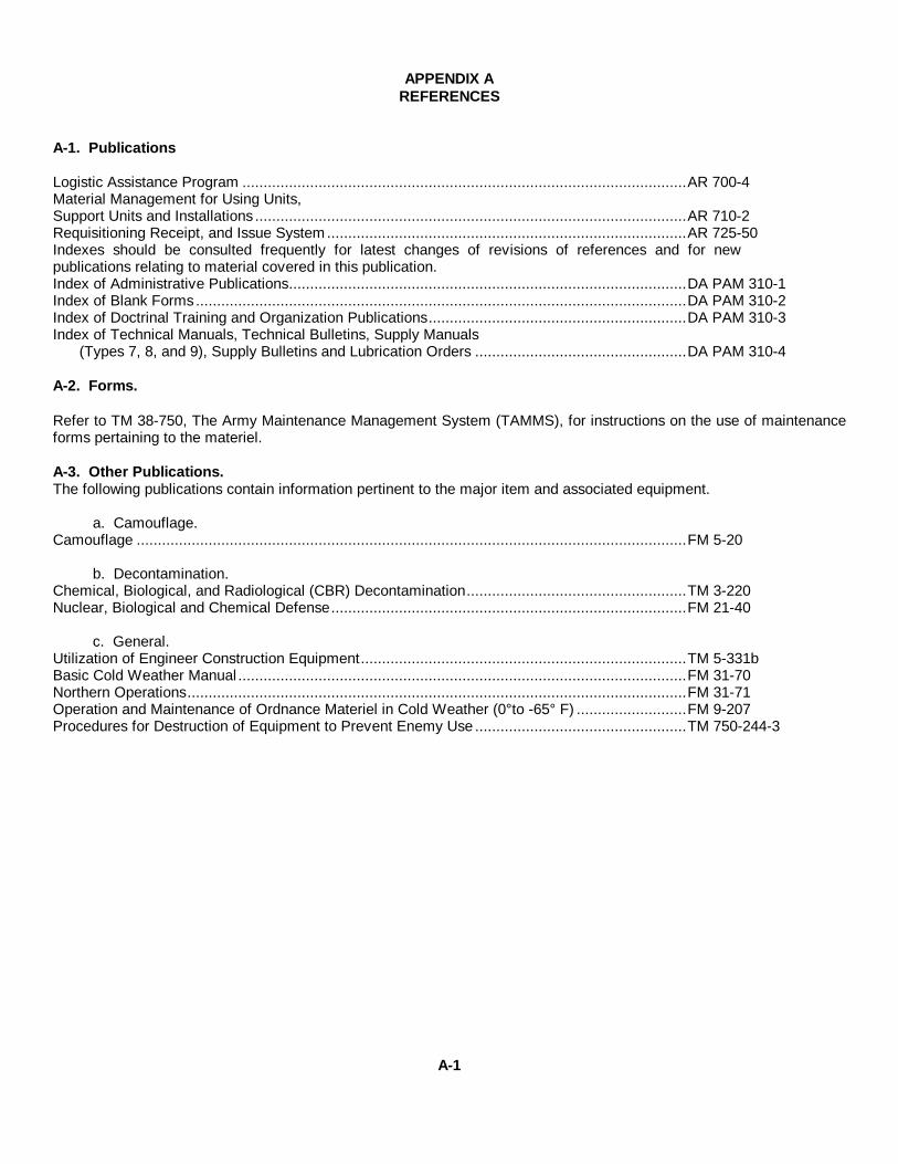
APPENDIX AREFERENCES
A-1. Publications
Logistic Assistance Program .........................................................................................................AR 700-4Material Management for Using Units,Support Units and Installations ......................................................................................................AR 710-2Requisitioning Receipt, and Issue System.....................................................................................AR 725-50Indexes should be consulted frequently for latest changes of revisions of references and for newpublications relating to material covered in this publication.Index of Administrative Publications..............................................................................................DA PAM 310-1Index of Blank Forms ....................................................................................................................DA PAM 310-2Index of Doctrinal Training and Organization Publications.............................................................DA PAM 310-3Index of Technical Manuals, Technical Bulletins, Supply Manuals
(Types 7, 8, and 9), Supply Bulletins and Lubrication Orders ..................................................DA PAM 310-4
A-2. Forms.
Refer to TM 38-750, The Army Maintenance Management System (TAMMS), for instructions on the use of maintenanceforms pertaining to the materiel.
A-3. Other Publications.The following publications contain information pertinent to the major item and associated equipment.
a. Camouflage.Camouflage ..................................................................................................................................FM 5-20
b. Decontamination.Chemical, Biological, and Radiological (CBR) Decontamination....................................................TM 3-220Nuclear, Biological and Chemical Defense....................................................................................FM 21-40
c. General.Utilization of Engineer Construction Equipment.............................................................................TM 5-331bBasic Cold Weather Manual..........................................................................................................FM 31-70Northern Operations......................................................................................................................FM 31-71Operation and Maintenance of Ordnance Materiel in Cold Weather (0°to -65° F) ..........................FM 9-207Procedures for Destruction of Equipment to Prevent Enemy Use ..................................................TM 750-244-3
A-1

APPENDIX AREFERENCES
d. Maintenance and RepairInspection, Care and Maintenance of Antifriction Bearings ............................................................TM 9-214Welding Theory and Application....................................................................................................TM 9-237Hand Portable Fire Extinguishers Approved for Army Users..........................................................TB 5-4200-200-10
e. Administrative Storage.Administrative Storage of Equipment ............................................................................................TM 740-90-1Preservation of USAMECOM Mechanical Equipment forShipment and Storage...................................................................................................................TB 740-97-2
A-2

APPENDIX BWARRANTY GUIDELINES
1. A warranty period of 12 months applies to the Paving Machine, Model BSF-400, manufactured by IOWA Mfg.Co. after delivery to the Government. This warranty applies to the end item, components and all supplies furnishedunder the contract.
2. Using units may not contact their local dealer. You must mail DA Form 2407 to the Maintenance Directorate,TARCOM, at the following address: US Army Tank-Automotive Material Readiness Command, ATTN: DRSTA-MVB,Warren Michigan 48090. To expedite actions you may call the information to AUTOVON 273-3349, 3439, or 3387 withthe information from your DA 2477, section 1, block 1 through 11, blocks 16, 17, 18 and 20.
3. General information:
a. DA Form 24)7 (prepared in accordance with warranty claim actions in TM 38-750) will be used to submitwarranty claims actions for end items when components, parts or assemblies are defective and are covered by amanufacturer's warranty. End items under warranty are identified by a decal plate and/or warranty statement included inthe operator's and maintenance manual for the end item. All warranty actions settled or unsettled will be reported to theNational Maintenance Point (NMP) on DL Form 2407. For warranties settled locally the DA Form 2407 will contain astatement "For Information Only" in block 35.
b. Maintenance activities in support of organizational maintenance are the responsible points of contact betweenthe originator of warranty claims and the National Maintenance Point (US Army Tank-Automotive Material ReadinessCommand, DRSTA-MVB, AUTOVON 273-3349, 273-3439, 273-3.387, Warren, Michigan 48090, which serves as the DLRepresentative with the contractor. in warranty matters. NOTE: In certain instances, the originating organization and thesupport activity are one and the same.
c. Before you take your equipment to a dealer for repair, whether or not it was necessary for you to go through theNMP (TARCOM), check with your local procurement office to see if a funds commitment document is needed.Sometimes, even though the majority of the repairs are covered by the warranty, there may be a small charge for normalmaintenance costs, i.e., oil filters, oil, etc. Further, the cause of damage could be determined by the dealer to be directlyrelated to "operator abuse." In that case, the Government may be obligated to pay for teardown services even if therepairs are no longer desired, or for the complete cost if repairs are to be completed by the dealer.
B-1

APPENDIX B
d. When the equipment is given to the dealer for repairs, find out how long the work will take, the extent of theproblem, if possible, and the charges, if any, which may be involved. Leave the name and telephone number of theperson to be contacted for pickup of the equipment and specifically state that he should be called as soon as the repairsare finished. In addition, state he should be telephoned if unexpected problems, costs and/or delays are encountered.Get the name and telephone number of the Service Manager, for any required follow-up purpose".
e. When you arrive to pick up your equipment after completion of services, make certain that you know exactlywhat repairs were performed and/or parts replaced. This is required for overall problem trend evaluation by the IMP andmust be identified upon completion of warranty services.
f. Telephone the NMP at TARCOM, AUTOVON 273-3349, 273-3439, and/or 273-3383 if:
(1) Your equipment requires repairs and you cannot obtain these services using the procedures listed above.
(2) The length of time required for repairs may seriously hamper your mission, or if the dealer's overall response toyour requirements are not satisfactory.
(3) You have any questions regarding warranty procedures - either in general or about a specific job. Do not waituntil your problems become critical.
g. Do not attempt to conduct negotiations regarding a breach of warranty. This is a function of the ContractingOfficer, through the NMP at TARCOM.
B-2

APPENDIX C
MAINTENANCE ALIOCATICN CHARTFOR
Paving Machine, Bituminous Material, Crawler Mtd.
Section I. INTRODUCTION
1. General: This Maintenance Allocation Chart designates responsibility for performance of Maintenance functions tospecific Maintenance categories.
2. Maintenance functions:
a. Inspect: To determine the serviceability of an item by comparing its physical, mechanical and/or electricalcharacteristics with established standards through examination.
b. Test: To verify serviceability and detect incipient failures by measuring the mechanical or electrical characteristicsof an item and comparing those characteristics with prescribed standards.
c. Service: Operations required periodically to keep an item in proper operating condition, i.e., to clean(decontaminate), to preserve, to drain, to paint, or to replenish fuel, lubricants, hydraulic fluids, or compressed airsupplies.
d. Adjust: To maintain, within prescribed limits, by bringing into proper or exact position, or by setting the operatingcharacteristics to specified parameters.
e. Align: To adjust specified variable elements of an item to bring about optimum or desired performance.
f. Calibrate: To determine and cause corrections to be made or to be adjusted on instruments or test measuring anddiagnostic equipment used in precision measurement. Consists of comparisons of two instruments, one of which is acertified standard of known accuracy, to detect and adjust any discrepancy in the accuracy of the instrument beingcompared.
g. Install: The act of emplacing, seating, or fixing into position an item, part, or module (component or assembly) in amanner to allow the proper functioning of an equipment or system.
h. Replace: The act of substituting a serviceable like type part, subassembly, or module (component or assembly) foran unserviceable counterpart.
i. Repair: The application of maintenance services or other maintenance actions to restore serviceability to an itemby correcting specific damage, fault, malfunction, or failure in a part, subassembly, module (component or assembly),end item, or system.
C-1
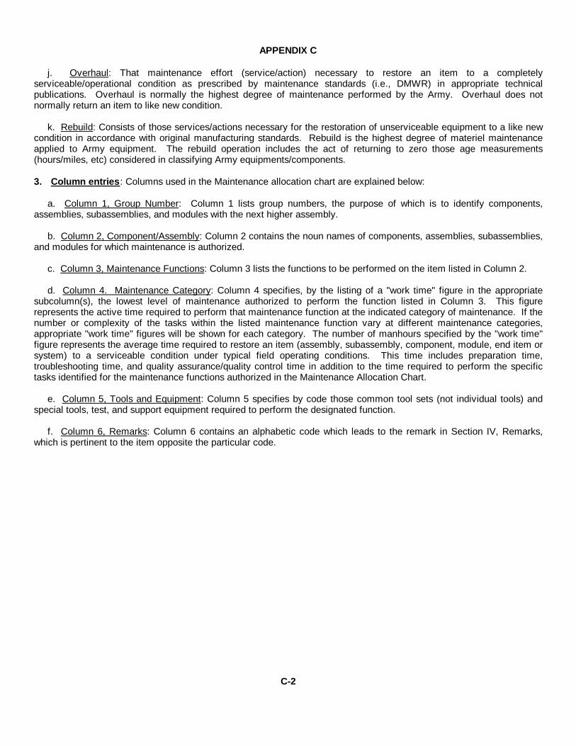
APPENDIX C
j. Overhaul: That maintenance effort (service/action) necessary to restore an item to a completelyserviceable/operational condition as prescribed by maintenance standards (i.e., DMWR) in appropriate technicalpublications. Overhaul is normally the highest degree of maintenance performed by the Army. Overhaul does notnormally return an item to like new condition.
k. Rebuild: Consists of those services/actions necessary for the restoration of unserviceable equipment to a like newcondition in accordance with original manufacturing standards. Rebuild is the highest degree of materiel maintenanceapplied to Army equipment. The rebuild operation includes the act of returning to zero those age measurements(hours/miles, etc) considered in classifying Army equipments/components.
3. Column entries: Columns used in the Maintenance allocation chart are explained below:
a. Column 1, Group Number: Column 1 lists group numbers, the purpose of which is to identify components,assemblies, subassemblies, and modules with the next higher assembly.
b. Column 2, Component/Assembly: Column 2 contains the noun names of components, assemblies, subassemblies,and modules for which maintenance is authorized.
c. Column 3, Maintenance Functions: Column 3 lists the functions to be performed on the item listed in Column 2.
d. Column 4. Maintenance Category: Column 4 specifies, by the listing of a "work time" figure in the appropriatesubcolumn(s), the lowest level of maintenance authorized to perform the function listed in Column 3. This figurerepresents the active time required to perform that maintenance function at the indicated category of maintenance. If thenumber or complexity of the tasks within the listed maintenance function vary at different maintenance categories,appropriate "work time" figures will be shown for each category. The number of manhours specified by the "work time"figure represents the average time required to restore an item (assembly, subassembly, component, module, end item orsystem) to a serviceable condition under typical field operating conditions. This time includes preparation time,troubleshooting time, and quality assurance/quality control time in addition to the time required to perform the specifictasks identified for the maintenance functions authorized in the Maintenance Allocation Chart.
e. Column 5, Tools and Equipment: Column 5 specifies by code those common tool sets (not individual tools) andspecial tools, test, and support equipment required to perform the designated function.
f. Column 6, Remarks: Column 6 contains an alphabetic code which leads to the remark in Section IV, Remarks,which is pertinent to the item opposite the particular code.
C-2

APPEDIX C
Section II. MAINTENANCE: ALLOCATION CHARTPaving Machine, Bituminous Material, Crawler, Mtd.
01 Engine 1,2,3,40100 Engine Assembly Test 2.0
Service 0.1Replace 16.0Repair 21.0Overhaul 48.0
Engine Mounts Replace 3.0
0101 Cylinder Block Test 5.0 1,2,3,4Replace 4.0Repair 20.0
Cylinder Sleeve Replace 3.0Cylinder Head Replace 4.0
Repair 4.0Overhaul 8.0
0102 Crankshaft Replace 5.0 1,2,3,4Main Bearings Replace 4.0Drive Pulley Replace 2.0
0103 Flywheel Replace 3.0 1,2
0104 Pistons & Connecting Rods Replace 3.0 1,2Repair 2.0
Rings & Bearings Replace .5
0105 Rocker Arms Replace .5 1,2Valve Springs Test .8
Replace .3Valve Exhaust Adjust 2.0
Replace 1.0Repair 2.0
Camshaft, Bearings &Gears Replace 4.0
0106 Oil Cooler Service .2 1,2Replace 1.0
Oil Pan Replace 1.5Repair 1.0
*The subcolumns are as follows:C--operator/crewO--organizationalF--direct supportH--general supportD--depot**Work times are included in DMWR
C-3
(5)TOOLS
ANDEQUIP
(3)
MAINTENANCEFUNCTION
(6)
REMARKS
(2)
COMPONENTASSEMBLY
(1)
GROUPNUMBER C O F H D
(4)
MAINTENANCE CATEGORY
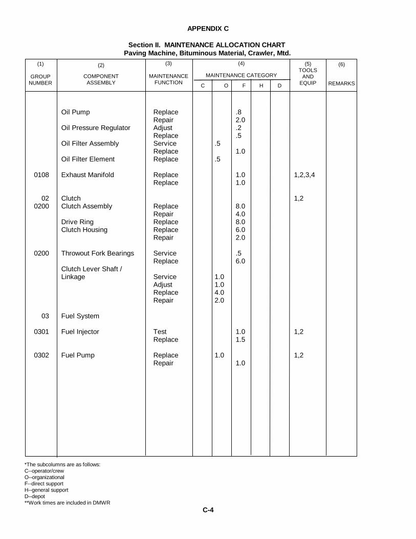
APPENDIX C
Section II. MAINTENANCE ALLOCATION CHARTPaving Machine, Bituminous Material, Crawler, Mtd.
Oil Pump Replace .8Repair 2.0
Oil Pressure Regulator Adjust .2Replace .5
Oil Filter Assembly Service .5Replace 1.0
Oil Filter Element Replace .5
0108 Exhaust Manifold Replace 1.0 1,2,3,4Replace 1.0
02 Clutch 1,20200 Clutch Assembly Replace 8.0
Repair 4.0Drive Ring Replace 8.0Clutch Housing Replace 6.0
Repair 2.0
0200 Throwout Fork Bearings Service .5Replace 6.0
Clutch Lever Shaft /Linkage Service 1.0
Adjust 1.0Replace 4.0Repair 2.0
03 Fuel System
0301 Fuel Injector Test 1.0 1,2Replace 1.5
0302 Fuel Pump Replace 1.0 1,2Repair 1.0
*The subcolumns are as follows:C--operator/crewO--organizationalF--direct supportH--general supportD--depot**Work times are included in DMWR
C-4
(5)TOOLS
ANDEQUIP
(3)
MAINTENANCEFUNCTION
(6)
REMARKS
(2)
COMPONENTASSEMBLY
(1)
GROUPNUMBER C O F H D
(4)
MAINTENANCE CATEGORY

APPENDIX C
Section II. MAINTENANCE ALLOCATION CHARTPaving Machine, Bituminous Material, Crawler, Mtd.
0304 Air Cleaner Service 0.4 1Replace 1.0Repair .5
Air Cleaner Element Replace 0.5
0305 Blower Air Intake Service 0.3 1,2Replace 1.0Repair 2.0
Air-Shut Down Adjust 0.5Replace 1.5Repair 2.0
*The subcolumns are as follows:C--operator/crewO--organizationalF--direct supportH--general supportD--depot**Work times are included in DMWR
C-5
(5)TOOLS
ANDEQUIP
(3)
MAINTENANCEFUNCTION
(6)
REMARKS
(2)
COMPONENTASSEMBLY
(1)
GROUPNUMBER C O F H D
(4)
MAINTENANCE CATEGORY
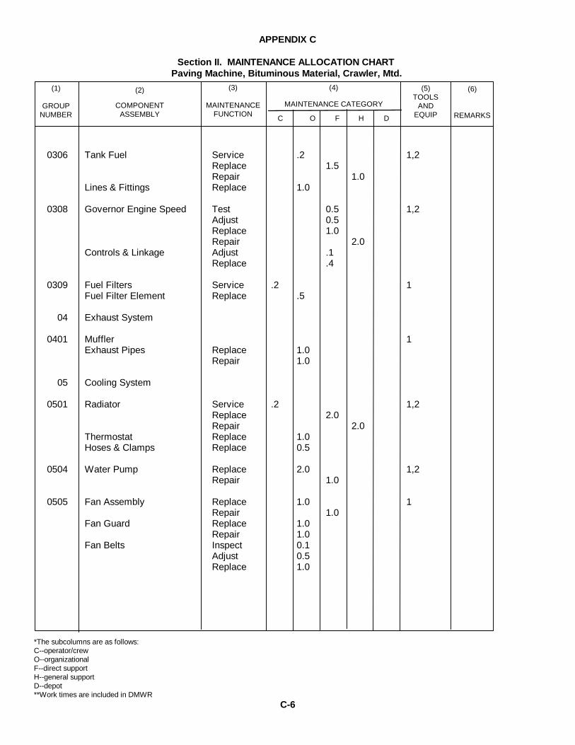
APPENDIX C
Section II. MAINTENANCE ALLOCATION CHARTPaving Machine, Bituminous Material, Crawler, Mtd.
0306 Tank Fuel Service .2 1,2Replace 1.5Repair 1.0
Lines & Fittings Replace 1.0
0308 Governor Engine Speed Test 0.5 1,2Adjust 0.5Replace 1.0Repair 2.0
Controls & Linkage Adjust .1Replace .4
0309 Fuel Filters Service .2 1Fuel Filter Element Replace .5
04 Exhaust System
0401 Muffler 1Exhaust Pipes Replace 1.0
Repair 1.0
05 Cooling System
0501 Radiator Service .2 1,2Replace 2.0Repair 2.0
Thermostat Replace 1.0Hoses & Clamps Replace 0.5
0504 Water Pump Replace 2.0 1,2Repair 1.0
0505 Fan Assembly Replace 1.0 1Repair 1.0
Fan Guard Replace 1.0Repair 1.0
Fan Belts Inspect 0.1Adjust 0.5Replace 1.0
*The subcolumns are as follows:C--operator/crewO--organizationalF--direct supportH--general supportD--depot**Work times are included in DMWR
C-6
(5)TOOLS
ANDEQUIP
(3)
MAINTENANCEFUNCTION
(6)
REMARKS
(2)
COMPONENTASSEMBLY
(1)
GROUPNUMBER C O F H D
(4)
MAINTENANCE CATEGORY

APPENDIX C
Section II. MAINTENANCE ALLOCATION CHARTPaving Machine, Bituminous Material, Crawler, Mtd.
06 Electrical System 1,2,50601 Alternator Test .1
Replace .5Repair 1.5
Generator Test .1Replace .5Repair 1.0
Generator & Alternator Inspect .1Drive Pully Repair .1
Alternator & Generator Inspect .1Drive Belts Adjust .2
Replace .2
0603 Starting Motor Test .1 1,2,5Replace .5Repair 1.5
0607 Instrument PanelAccessories Replace .5 1,5
Replace .7
0608 Circuit Breakers Test .1 1,5Replace .3
0609 Head, Tail, & ConveyorLights Replace .2 1,5
Repair .4
0610 Flasher Replace .2 1,5Limit Switches Replace .2Screed Lift Switch Replace .2
0611 Horn Assembly Replace .3 1,5
0612 Batteries Storage Inspect 0.1 1,5Test .3Replace 0.5Service 0.2
*The subcolumns are as follows:C--operator/crewO--organizationalF--direct supportH--general supportD--depot**Work times are included in DMWR
C-7
(5)TOOLS
ANDEQUIP
(3)
MAINTENANCEFUNCTION
(6)
REMARKS
(2)
COMPONENTASSEMBLY
(1)
GROUPNUMBER C O F H D
(4)
MAINTENANCE CATEGORY
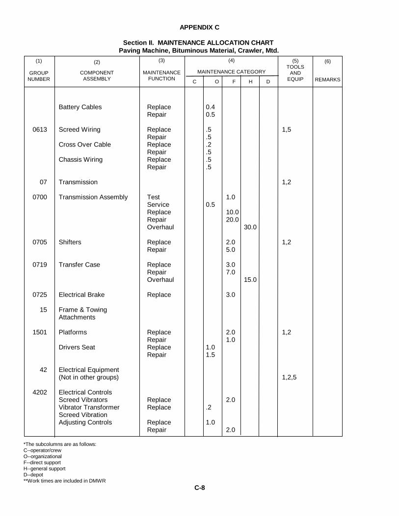
APPENDIX C
Section II. MAINTENANCE ALLOCATION CHARTPaving Machine, Bituminous Material, Crawler, Mtd.
Battery Cables Replace 0.4Repair 0.5
0613 Screed Wiring Replace .5 1,5Repair .5
Cross Over Cable Replace .2Repair .5
Chassis Wiring Replace .5Repair .5
07 Transmission 1,2
0700 Transmission Assembly Test 1.0Service 0.5Replace 10.0Repair 20.0Overhaul 30.0
0705 Shifters Replace 2.0 1,2Repair 5.0
0719 Transfer Case Replace 3.0Repair 7.0Overhaul 15.0
0725 Electrical Brake Replace 3.0
15 Frame & TowingAttachments
1501 Platforms Replace 2.0 1,2Repair 1.0
Drivers Seat Replace 1.0Repair 1.5
42 Electrical Equipment(Not in other groups) 1,2,5
4202 Electrical ControlsScreed Vibrators Replace 2.0Vibrator Transformer Replace .2Screed VibrationAdjusting Controls Replace 1.0
Repair 2.0
*The subcolumns are as follows:C--operator/crewO--organizationalF--direct supportH--general supportD--depot**Work times are included in DMWR
C-8
(5)TOOLS
ANDEQUIP
(3)
MAINTENANCEFUNCTION
(6)
REMARKS
(2)
COMPONENTASSEMBLY
(1)
GROUPNUMBER C O F H D
(4)
MAINTENANCE CATEGORY
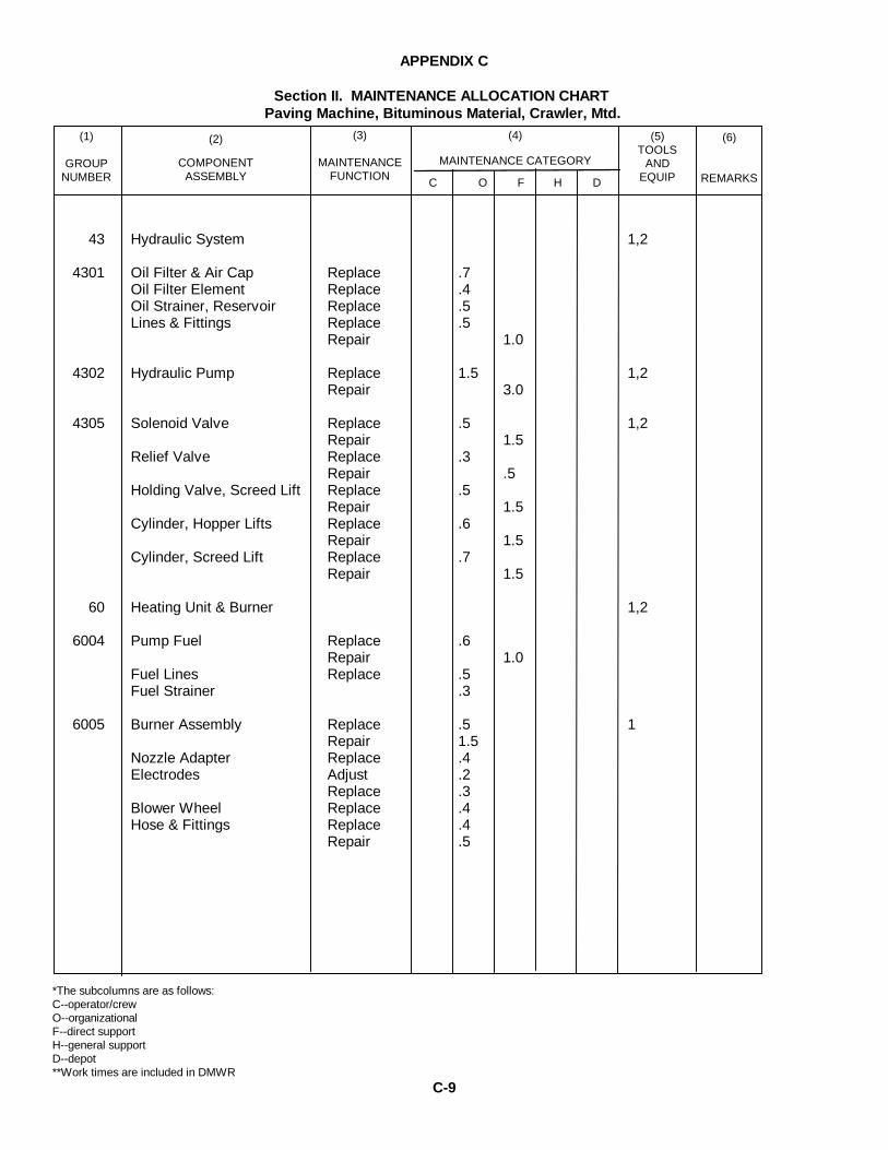
APPENDIX C
Section II. MAINTENANCE ALLOCATION CHARTPaving Machine, Bituminous Material, Crawler, Mtd.
43 Hydraulic System 1,2
4301 Oil Filter & Air Cap Replace .7Oil Filter Element Replace .4Oil Strainer, Reservoir Replace .5Lines & Fittings Replace .5
Repair 1.0
4302 Hydraulic Pump Replace 1.5 1,2Repair 3.0
4305 Solenoid Valve Replace .5 1,2Repair 1.5
Relief Valve Replace .3Repair .5
Holding Valve, Screed Lift Replace .5Repair 1.5
Cylinder, Hopper Lifts Replace .6Repair 1.5
Cylinder, Screed Lift Replace .7Repair 1.5
60 Heating Unit & Burner 1,2
6004 Pump Fuel Replace .6Repair 1.0
Fuel Lines Replace .5Fuel Strainer .3
6005 Burner Assembly Replace .5 1Repair 1.5
Nozzle Adapter Replace .4Electrodes Adjust .2
Replace .3Blower Wheel Replace .4Hose & Fittings Replace .4
Repair .5
*The subcolumns are as follows:C--operator/crewO--organizationalF--direct supportH--general supportD--depot**Work times are included in DMWR
C-9
(5)TOOLS
ANDEQUIP
(3)
MAINTENANCEFUNCTION
(6)
REMARKS
(2)
COMPONENTASSEMBLY
(1)
GROUPNUMBER C O F H D
(4)
MAINTENANCE CATEGORY
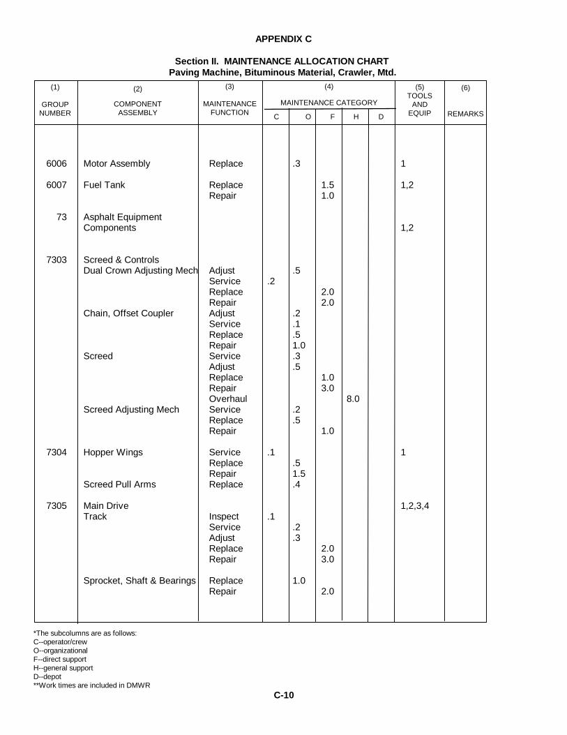
APPENDIX C
Section II. MAINTENANCE ALLOCATION CHARTPaving Machine, Bituminous Material, Crawler, Mtd.
6006 Motor Assembly Replace .3 1
6007 Fuel Tank Replace 1.5 1,2Repair 1.0
73 Asphalt EquipmentComponents 1,2
7303 Screed & ControlsDual Crown Adjusting Mech Adjust .5
Service .2Replace 2.0Repair 2.0
Chain, Offset Coupler Adjust .2Service .1Replace .5Repair 1.0
Screed Service .3Adjust .5Replace 1.0Repair 3.0Overhaul 8.0
Screed Adjusting Mech Service .2Replace .5Repair 1.0
7304 Hopper Wings Service .1 1Replace .5Repair 1.5
Screed Pull Arms Replace .4
7305 Main Drive 1,2,3,4Track Inspect .1
Service .2Adjust .3Replace 2.0Repair 3.0
Sprocket, Shaft & Bearings Replace 1.0Repair 2.0
*The subcolumns are as follows:C--operator/crewO--organizationalF--direct supportH--general supportD--depot**Work times are included in DMWR
C-10
(5)TOOLS
ANDEQUIP
(3)
MAINTENANCEFUNCTION
(6)
REMARKS
(2)
COMPONENTASSEMBLY
(1)
GROUPNUMBER C O F H D
(4)
MAINTENANCE CATEGORY
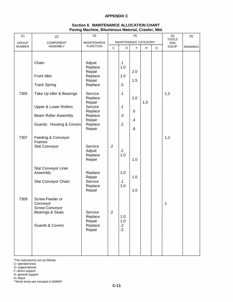
APPENDIX C
Section II. MAINTENANCE ALLOCATION CHARTPaving Machine, Bituminous Material, Crawler, Mtd.
Chain Adjust .1Replace 1.0Repair 2.0
Front Idler Replace 1.0Repair 1.5
Track Spring Replace .5
7305 Take Up Idler & Bearings Service .1 1,2Replace 1.0Repair 1.0
Upper & Lower Rollers Service .1Replace .5
Beam Roller Assembly Replace .3Repair .4
Guards: Housing & Covers Replace .2Repair .8
7307 Feeding & Conveyor 1,2FramesSlat Conveyor Service .2
Adjust .2Replace 1.0Repair 1.0
Slat Conveyor LinerAssembly Replace 1.0
Repair 1.0Slat Conveyor Chain Service .1
Replace 1.0Repair 1.0
7309 Screw Feeder orConveyor 1Screw ConveyorBearings & Seals Service .2
Replace 1.0Repair 1.0
Guards & Covers Replace .2Repair .5
*The subcolumns are as follows:C--operator/crewO--organizationalF--direct supportH--general supportD--depot**Work times are included in DMWR
C-11
(5)TOOLS
ANDEQUIP
(3)
MAINTENANCEFUNCTION
(6)
REMARKS
(2)
COMPONENTASSEMBLY
(1)
GROUPNUMBER C O F H D
(4)
MAINTENANCE CATEGORY

APPENDIX C
Section II. MAINTENANCE ALLOCATION CHARTPaving Machine, Bituminous Material, Crawler, Mtd.
7309 Grease Fittings & Piping Service .1 1,2Replace .2
Chain: SprocketBearings & Idler Service .1
Adjust .1Replace 2.0Repair 1.0
Shaft: BearingsDrive Sprocket: &Chain Service .1
Replace .4Repair .8
Screw Extension Service .1Replace .2Repair .2
Remote Screw Control Adjust .1Repair .1
Material Retaining Plates Service .1Replace .2Repair .4
7313 Screed Vibrator Agitator Adjust .2 1,2Replace .4Repair .6
Screed Extender Adjust .1Replace .6Repair .8
Screed Shim Pack Adjust .1Screed Strik Off Adjust .2
Replace .4Repair .6
Screed Adjusting Cables Replace .5
76 Fire Fighting Equipment 1
7638 Portable Fire Extinguisher Replace .2
*The subcolumns are as follows:C--operator/crewO--organizationalF--direct supportH--general supportD--depot**Work times are included in DMWR
C-12
(5)TOOLS
ANDEQUIP
(3)
MAINTENANCEFUNCTION
(6)
REMARKS
(2)
COMPONENTASSEMBLY
(1)
GROUPNUMBER C O F H D
(4)
MAINTENANCE CATEGORY

MAINTENANCE ALLOCATION CHART FORPAVING MACHINE, BITUMINOUS MATERIAL
CRAWLER MTD., DED
APPENDIX CSECTION III - TOOL AND TEST EQUIPMENT REQUIREMENTSTOOL OR TEST
EQUIPMENTREFERENCE
CODEMAINTENANCE
CATEGORY NOMENCLATURENATIONAL / NATOSTOCK NUMBER
TOOLNUMBER
Unless otherwise noted all maintenancefunctions can be accomplished with thetools contained in the following commontwo sets.
1 O, F, H Shop Equip Contact Maint.TRD MTD (SC 4940-97-CL-E-05)
4940-00-294-9518 T10138
1 O, F, H Shop Equip Org Repair,Light TRK MTD (SC 4940-97-CL-E04
4940-00-294-9516 T13152
1 O, F, H Tool Kit Automotive Maint,Org Maint Common #1 (SC4910-95-CL-A72)
410-00-754-0654 W32593
1 O, F, H Tool Kit Automotive Maint,Org Maint Common #2 (SC4910-95-CL-W26)
5180-00-177-7033 W33004
1 O, F, H Shop Equip Auto Maint andRepair Org Maint Supp #1(SC 4910-95-CL-A73)
4910-00-754-0653 W32867
1 O, F, H Shop Equip Welding FieldMaint (SC 3470-95-CL-A08)
3470-00-357-7268 T16714
1 O, F, H Tool Set, Veh Full TrackedSugg #2 SC 4940-95-CL-A08
4940-00-7541-0743 W65747
2 F, H Shop Equip Gen PurpRepair Semitrir MTD (SC4940-97-CL-E03)
4940-00-287-4894 T10549
2 F, H Tool Kit Automotive, Fueland Elec Sys Repair (SC4910-95-CL-A50)
4910-00-754-0655 W32456
2 F, H Tool Kit, Master Mechanicand Equip Maint andRepair (SC 5180-90-CL-E05)
5180-00-699-5273 W45060
C-13

MAINTENANCE ALLOCATION CHART FORPAVING MACHINE, BITUMINOUS MATERIAL
CRAWLER MTD., DED
APPENDIX CSECTION III - TOOL AND TEST EQUIPMENT REQUIREMENTSTOOL OR TEST
EQUIPMENTREFERENCE
CODEMAINTENANCE
CATEGORY NOMENCLATURENATIONAL / NATOSTOCK NUMBER
TOOLNUMBER
2 F, H Shop Set, Fuel and ElecSys Field Maint Basic (SC4910-95-CL-A01)
4910-00-754-0714 T30414
2 F, H Shop Set, Fuel and ElecSys Field Maint Basic Sup#2 (SC 4910-95-CL-A65)
4910-00-390-7775 T30688
2 Shop Equip Machine Shop,Field Maint Basic (SC3470-95-CL-A02)
3470-00-754-0708 T15644
2 Measuring Lay Out ToolSet, Mach (SC-5280-95-CL-A02)
5280-00-511-1950 W44512
2 Tool Kit Body And FenderRepair
5180-00-754-0643 W33689
3 Wrench Set Socket, ¾ ”Drive Hex Type
5310-00-754-0743 W65747
4 O, F, H Wrench Torque, ¾ ” Drive500 lb Cap
5120-00-542-5577 Y84966
5 O, F, H Multimeter 6625-00-999-7465 M80242
C-14

APPENDIX D
CCE MANUFACTURER FIELD CAMPAIGNS AND MODIFICATION PROCEDURES
D-1

APPENDIX E
BASIC ISSUE ITEMS LIST
(1) (2) (3) (4) (5)QUANTITY
MFR PART NO. MFR FED CODE DESCRIPTION UNIT OF ISSUE FURNISHEDW/EQUIP
45500-020-06 31245 Wrench, Allen 5/16” EA 145500-036-06 31245 Gage, Strike Off EA 145500-750-06 31245 Wrench, Crown Adj EA 1
E-1

APPENDIX F
ITEMS TROOP INSTALLED OR AUTHORIZED LIST(1)
SMRCODE
(2)
NATIONAL STOCKNUMBER
(3)DESCRIPTION
REF No & MFR USABLECODE ON CODE
(4)
UNITOF
MEAS
(5)
QTYAUTH
7520-00-559-9618
7510-00-889-3494
4210-00-889-2221
4930-00-277-9525
4930-00-204-2550
4930-00-288-1511
NOTE: The following items areoverpacked with the paver.
Case, Cotton Duck: MIL-B-11743(81349)
Log Book Binders MIL-B-43064
NOTE: The following items areauthorized but not issued with thepaver.
Extinguisher, Fire Dry Chemical
Grease Gun, Hand
Adapter, Grease Gun Coupling, Rigid
Adapter, Grease Gun Coupling, Flex
EA
EA
EA
EA
EA
EA
1
1
1
1
1
1
F-1

APPENDIX G
INITIAL RECOMMENDATIONPRESCRIBED LOAD LIST (PLL)
AUTHORIZED STOCKAGE LIST (ASL)
END ITEM:Paving Machine, Bituminous
MAKE:IOWA Mfg Co
MODEL:BSF-400
MFR PART NO:N/A
NSN:3895-01-063-7891
SERIAL NUMBER RANGE5627 TO 35633
DATEMar 80
QTY OF PARTS REQ’DFOR NO. OF END ITEMS
SMR CODE NATIONAL STOCKNUMBER
PART NUMBER FSCM PART DESCRIPTION U/M PLL ASL
1-5 1-5 6-20 21-50
PAOZZPAOZZPAOZZPAOZZPAOZZPAOZZPAOZZPAOZZPAOZZPAOZZPAOZZ
2940-00-019-80872910-00-890-24362910-00-792-89854930-01-038-93073030-00-865-24703030-00-421-15533030-00-529-04663030-00-668-72015977-01-089-67834330-00-073-03712940-00-129-9757
55749785573261557496145652-512-1551313955139228B66MS39277-04045652-505-241551P11-8159
7258270040725823124572582725822416196906312450224918265
Element, Oil FilterElement, Fuel Filter SecondaryElement, Fuel Filter PrimaryNozzle, Screed BurnerBelt Set, Crankshaft PulleyBelt Set, Water PumpBelt, Generator DriveBelt Set, Alternator DriveElectrode, Screed BurnerElement, Hyd System Oil FilterElement, Air Cleaner
$1.32.511.591.503.552.115.664.001.704.117.81
EAEAEAEAEAEAEAEAEAEAEA
1112
211
11121111211
12221111221
22221111221
PAGE 1 OF 1
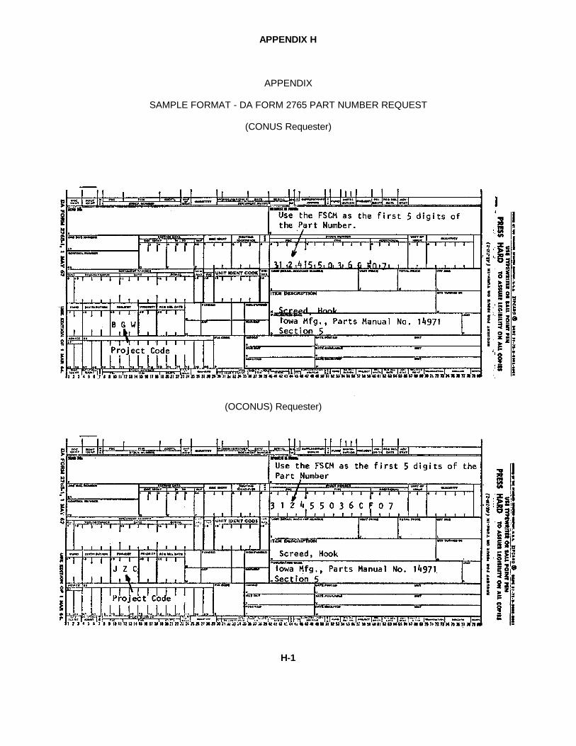
APPENDIX H
APPENDIX
SAMPLE FORMAT - DA FORM 2765 PART NUMBER REQUEST
(CONUS Requester)
(OCONUS) Requester)
H-1
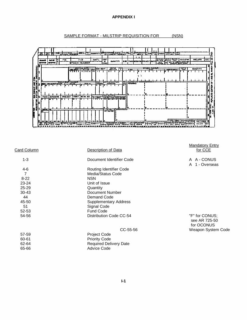
APPENDIX I
SAMPLE FORMAT - MILSTRIP REQUISITION FOR (NSN)
Mandatory EntryCard Column Description of Data for CCE
1-3 Document Identifier Code A∅A - CONUSA∅1 - Overseas
4-6 Routing Identifier Code7 Media/Status Code
8-22 NSN23-24 Unit of Issue25-29 Quantity30-43 Document Number
44 Demand Code45-50 Supplementary Address
51 Signal Code52-53 Fund Code54-56 Distribution Code CC-54 "F" for CONUS;
see AR 725-50for OCONUS
CC-55-56 Weapon System Code57-59 Project Code60-61 Priority Code62-64 Required Delivery Date65-66 Advice Code
I-1
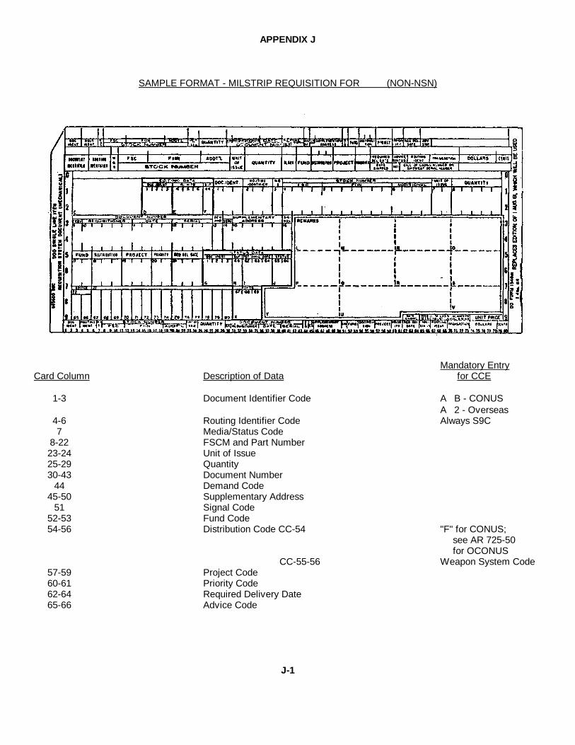
APPENDIX J
SAMPLE FORMAT - MILSTRIP REQUISITION FOR (NON-NSN)
Mandatory EntryCard Column Description of Data for CCE
1-3 Document Identifier Code A∅B - CONUSA∅2 - Overseas
4-6 Routing Identifier Code Always S9C7 Media/Status Code
8-22 FSCM and Part Number23-24 Unit of Issue25-29 Quantity30-43 Document Number
44 Demand Code45-50 Supplementary Address
51 Signal Code52-53 Fund Code54-56 Distribution Code CC-54 "F" for CONUS;
see AR 725-50for OCONUS
CC-55-56 Weapon System Code57-59 Project Code60-61 Priority Code62-64 Required Delivery Date65-66 Advice Code
J-1

APPENDIX J (CONT'D)
Mandatory EntryCard Column Description of Data for CCE
67-69 Blank
70 Identification code applicable toentry in cc 71-80.
A - Technical order or TechnicalManual.
B - End Item Identification
C - Noun Description
D- Drawing or Specification No.
71-80 Reference Identification Identification ofreference specifiedin cc 70
J-2

APPENDIX E
SAMPLE FORMAT - MILSTRIP REQUISITION FOR (NON-NSN)(MANUAL)
FORMDD 1 JAN 71 1348-6 NON-NSN REQUISITION (MANUAL)
K-1

APPENDIX K
INSTRUCTIONS
This form will only be used in those cases where the manufacturer’s code and part number exceed the spacesallocated in card columns 8 - 22 of the requisition.
Mandatory EntryCard Column Description of Data for CCE
1 - 3 Document Identifier Code A∅E - CONUSA∅5 - OCONUS
4 - 6 Routing Identifier Code Always S9C
7 Media Status Code
8 - 22 FSCM and Part Number Leave BlankEnter In Block 1under IdentificationData
23-24 Unit of Issue
25-29 Quantity
30-43 Document Number
44 Demand Code
45-50 Supplementary Address
51 Signal Code
52-53 Fund Code
54-56 Distribution Code CC 54 "F for CONUS. (SeeAR 725-50 forOCONUS)
CC 55-56 Weapon System Code
57-59 Project Code
60-61 Priority Code
62-64 Required Delivery Date
65-66 Advice Code
67-80 Blank
IDENTIFICATION DATA - Lower half of DD Form 13418-6, complete Blocks 1 thru 9.
K-2

APPENDIX L
CROSS REFERENCE PART NUMBER LIST
Iowa P/N Iowa FSCM Prime P/N Prime FSCM
45003-500-02 31245 748-0329 6381045033-501-01 “ 540-0004 “45003-502-02 “ 830-0008 “45003-502-03 “ 800-3042 “45093-503-01 “ 5301-101-01 “45033-504-02 ” 5204-451-14 “45003-505-31 “ 5303-111-001 “45003-505-13 “ DX11576A “45080-001-07 “ V230-8-1C549 6298345090-001-36 “ 3011A 0798345090-002-32 “ XB265 1791345090-002-43 “ C1301656D 1629445090-503-11 “ 4022030 0748845090-526-20 “ XA605 1791345090-526-35 “ 990-90003448 1629445130-091-95 “ 42687 6003845130-001-08 “ 385 “45130-001-09 “ 476 “45130-002-03 “ 42620 “45130-002-04 “ 382A “45130-002-06 “ 472A “45134-001-14 “ 3310 4333445134-001-20 “ 3210 “45134-001-21 “ 3308 “45134-001-22 “ 3309 “45134-001-24 “ 3313 (433343309) “45134-001-25 “ 5207 “45134-001-26 “ 3310G “45134-001-27 “ 3307G “45200-008 “ 450286 8159645200-021 “ 50145S “45200-040 “ 55147S “45200-181 “ 55088S “45200-183 “ 50350S “45200-184 “ 50230S “45200-191 “ 63X1345 7368045252-005-01 “ 7107-256 0798845259-508-14 “ 3-8 0269745259-508-47 “ 2-118 “45377-504-01 “ 5-153X 7244745476-001-02 “ DB7493 7647445550-003-31 “ X117C8 6120845550-019-06 “ 6187A “45550-022-10 “ 6314G “45551-263-01 “ 5204-751-02 6381045552-258-01 “ 315380 1896745652-505-24 “ SC5813 34181
L-1

APPENDIX L
CROSS REFERENCE PART NUMBER LIST
Iowa P/N Iowa FSCM Prime P/N Prime FSCM
45652-512-02 31245 1-3/8LX1/SFNPT 7189545652-512-15 “ 1-35GPH “45652-528-01 “ J2BC100-3 9916645652-529-01 “ AA524-316-1 6039945865 002-16 “ 6464910 7004045865-003-04 “ 6402618 “46098-400-09 “ B122-1061 9450646150-oo0-75 “ FM3V2B3 6612746165-001-40 “ 30055-10 1344546165-001-41 “ CDM15-1 8264746165-002-72 “ CDM35-1 “46165-004-79 “ 30055-15 1344546200-001-13 “ 1LS 1 9192946200-003-75 “ 95582 1344546200-009-06 “ 1TL1-2 9192946200-009-08 “ 2TL1-1 9192946200-009-11 “ 1TL1-6 9192946200-009-18 “ 2TL1-3 9192946205-001-12 “ SA2263-12 7838846225-001-07 “ AEA33353 9491646225-002-07 “ 6474386 7004046225-003-02 “ 6717-134 1612746260-001-10 “ 20-141 7178546955-001-35 “ 1N2071A 0471350005-020-01 “ ANS1-40CONN 8423350005-080-01 “ ANS1-80CONN “7033-006 “ W05 526767048-014 K21820 “7048-015 “ K21807 “7048-016 “ K21805 “7048-046 “ K22420 “7048-047 “ K22407 “7048-048 “ K22405 “7118-031 “ B66 241617166-005 “ 7506 433347166-11 “ 3209 “7166-015 “ 3L13 “7238-127 “ 59-062-312-1500 225997258-004 “ 6420 600387258-013 “ 6454 “7306-001 “ 3920 “7306-016 “ 3982 “7376-001 “ 59425 “7376-005 “ 59175 “7441-041 “ 3V400 (MS 39277-40) 2416145)8)-510-22 “ 1551 02249
“ “ DP-752-10 5059045690-001-21-03 “ P11-8159 18265
L-2

APPENDIX M
APPENDIX _________
MAINTENANCE AND OPERATING SUPPLY LIST
NOMENCLATURE:Paving Machine, Bituminous
MAKE:IOWA Mfg Co
MODEL:BSF-400
MFR PART NO:N/A
NSN:3895-01-063-7891
SERIAL NUMBER RANGE5627 TO 5633
DATEMar 80
(1)
COMPONENTAPPLICATION
(2)MFR PART NO.
ORNAT’L STOCK NO.
(3)
DESCRIPTION
(4)QTY REQF/INITIAL
OPN
(5)QTY REQF/8 HRS
OPN
(6)
NOTESEngine Crankcase
Fuel Tank, Engine
Cooling System
Hydraulic System
Fuel TankScreed Heater
9150-00-188-9858
9150-00-186-6668
9150-00-286-5296
6850-00-181-7933
9150-00-843-1636
9140-00-247-4365
Oil, Lubricating OE/HDO 30MIL-L-2104
Oil, Lubricating OE/HDO10MIL-L-2104
Diesel Fuel, DF2
Anti-Freeze, PermanentMIL-A-46153
Automotive Trans Fluid(Dexron Type F)
Fuel Oil
14 qt.
33 gal.
13 qt.
10 gal.
12.5 gal.
*
*
*
*
*
5 gal.
5 gal.
55 gal. Drum
50-50-solution
* As Required
M-1
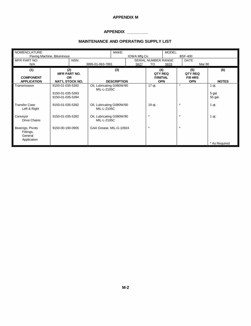
APPENDIX M
APPENDIX _________
MAINTENANCE AND OPERATING SUPPLY LIST
NOMENCLATURE:Paving Machine, Bituminous
MAKE:IOWA Mfg Co
MODEL:BSF-400
MFR PART NO:N/A
NSN:3895-01-063-7891
SERIAL NUMBER RANGE5627 TO 5633
DATEMar 80
(1)
COMPONENTAPPLICATION
(2)MFR PART NO.
ORNAT’L STOCK NO.
(3)
DESCRIPTION
(4)QTY REQF/INITIAL
OPN
(5)QTY REQF/8 HRS
OPN
(6)
NOTESTransmission
Transfer CaseLeft & Right
ConveyorDrive Chains
Bearings, PivotsFittings,GeneralApplication
9150-01-035-5392
9150-01-035-53939150-01-035-5394
9150-01-035-5392
9150-01-035-5392
9150-00-190-0905
Oil, Lubricating G080W/90MIL-L-2105C
Oil, Lubricating G080W/90MIL-L-2105C
Oil, Lubricating G080W/90MIL-L-2105C
GAA Grease, MIL-G-10924
17 qt.
19 qt.
*
*
*
*
*
*
1 qt.
5 gal.55 gal.
1 qt.
1 qt.
* As Required
M-2

APPENDIX N
PREVENTIVE MAINTENANCE CHECKS AND SERVICES
Maintenance Forms and Records
Every mission begins and ends with the paperwork. There isn't much of it, but you have to keep it up. The forms andrecords you fill out have several uses. They are a permanent record of the services, repairs, and modifications made onyour vehicle. They are reports to organizational maintenance and to your commander. And they are a checklist for youwhen you want to know what is wrong with the vehicle after its last use, and whether those faults have been fixed. Forthe information you need on forms and records, see TM 38-750.
Preventive Maintenance Checks and Services
1. Do your before (B) PREVENTIVE MAINTENANCE just before you operate the vehicle. Pay attention to theCAUTIONS and WARNINGS.
2. DURING checks and services (D) of PREVENTIVE MAINTENANCE will be performed while the equipment and/orits component systems are in operation.
3. Do your after (A) PREVENTIVE MAINTENANCE right after operating the vehicle. Pay attention to the CAUTIONSand WARNINGS.
4. Do your weekly (W) PREVENTIVE MAINTENANCE weekly.
5. Do your monthly (M) PREVENTIVE MAINTENANCE once a month.
6. If something doesn't work, troubleshoot it with the instructions in this manual or notify your supervisor.
7. Always do your PREVENTIVE MAINTENANCE in the same order so it gets to be a habit. Once you've had somepractice, you'll spot anything wrong in a hurry.
8. If anything looks wrong and you can't fix it, write it on your DA Form 2404. If you find something seriously wrong,report it to organizational maintenance RIGHT NOW.
9. When you do your PREVENTIVE MAINTENANCE, take along the tools you need to make all the checks. Youalways need a rag or two.
A - Keep it clean: Dirt, grease, oil, and debris only get in the way and may cover up a serious problem. Clean as youwork and as needed. Use dry cleaning solvent (SD-2) on all metal surfaces. Use soap and water when you clean rubberor plastic material.
WARNING
Dry cleaning solvent, used to clean parts is potentially dangerous to personnel andproperty. Do not use near open flame or excessive heat. Flash point of solvent is 100°F- 138°F.
N-1
APPENDIX N
B - Bolts, nuts, and screws: Check them all for obvious looseness, missing, bent or broken condition. You can't try themall with a tool, of course, but look for chipped paint, bare metal, or rust around bolt heads. If you find one you think isloose, tighten it, or report it to organizational maintenance if you can't tighten it.
C - Welds: Look for loose or chipped paint, rust, or gaps where parts are welded together. If you find a bad weld, report itto organizational maintenance.
D - Electric wires and connectors: Look for cracked or broken insulation, bare wires, and loose or broken connectors.Tighten loose connectors and make sure the wires are in good shape.
E - Hoses and fluid lines: Look for wear, damage, and leaks, and make sure clamps and fittings are tight. Wet spotsshow leaks, of course. But a stain around a fitting or connector can mean a leak. If a leak comes from a loose fitting orconnector, tighten it. If something is broken or worn out, report it to organizational maintenance.
10. It is necessary for you to know how fluid leakage affects the status of your vehicle. The following are definitions ofthe types/classes of leakage an operator or crew member needs to know to be able to determine the status of his/hervehicle. Learn, then be familiar with them and REMEMBER - WHEN IN DOUBT, NOTIFY YOUR SUPERVISOR!
Leakage Definitions for Crew/Operator PMCS
Class I Seepage of fluid (as indicated by wetness or discoloration) not great enough to form drops.
Class II Leakage of fluid great enough to form drops but not enough to cause drops to drip from itembeing checked/inspected.
Class III Leakage of fluid great enough to form drops that fall from the item being checked/inspected.
CAUTION
EQUIPMENT OPERATION IS ALLOWABLE WITH MINOR LEAKAGES (CLASS I ORII). OR COURSE, CONSIDERATION MUST BE GIVEN TO THE FLUID CAPACITY INTHE ITEM/SYSTEM BEING CHECKED/INSPECTED. WHEN IN DOUBT, NOTIFYYOUR SUPERVISOR.
N-2
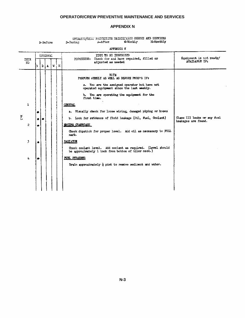
OPERATOR/CREW PREVENTIVE MAINTENANCE AND SERVICES
APPENDIX N
N-3
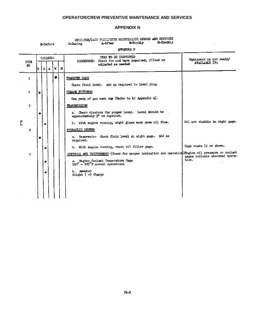
OPERATOR/CREW PREVENTIVE MAINTENANCE AND SERVICES
APPENDIX N
N-4

OPERATOR/CREW PREVENTIVE MAINTENANCE AND SERVICES
APPENDIX N
N-5

OPERATOR/CREW PREVENTIVE MAINTENANCE AND SERVICES
APPENDIX N
N-6
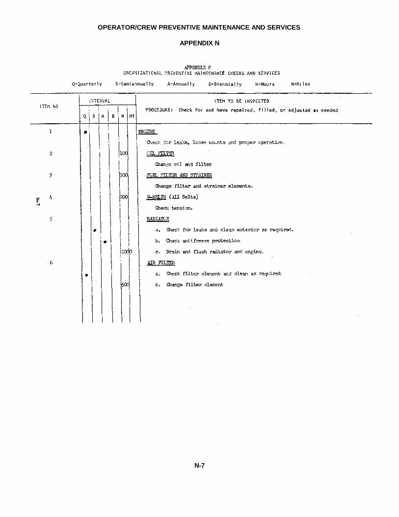
OPERATOR/CREW PREVENTIVE MAINTENANCE AND SERVICES
APPENDIX N
N-7
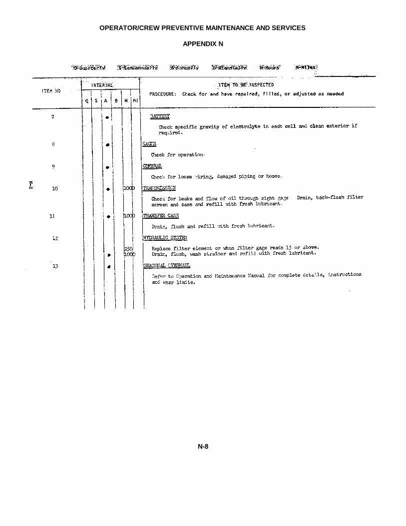
OPERATOR/CREW PREVENTIVE MAINTENANCE AND SERVICES
APPENDIX N
N-8
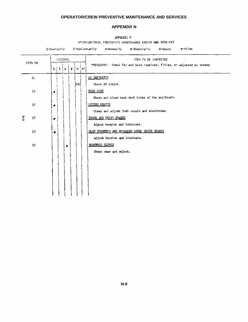
OPERATOR/CREW PREVENTIVE MAINTENANCE AND SERVICES
APPENDIX N
N-9
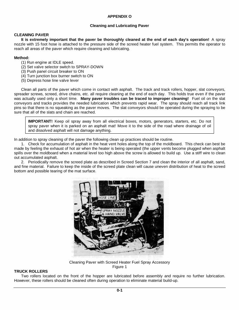
APPENDIX O
Cleaning and Lubricating Paver
CLEANING PAVERIt is extremely important that the paver be thoroughly cleaned at the end of each day's operation! A spray
nozzle with 15 foot hose is attached to the pressure side of the screed heater fuel system. This permits the operator toreach all areas of the paver which require cleaning and lubricating.
Method:(1) Run engine at IDLE speed.(2) Set valve selector switch to SPRAY-DOWN(3) Push panel circuit breaker to ON(4) Turn junction box burner switch to ON(5) Depress hose line valve lever
Clean all parts of the paver which come in contact with asphalt. The track and track rollers, hopper, slat conveyors,spreader screws, screed, drive chains, etc. all require cleaning at the end of each day. This holds true even if the paverwas actually used only a short time. Many paver troubles can be traced to improper cleaning! Fuel oil on the slatconveyors and tracks provides the needed lubrication which prevents rapid wear. The spray should reach all track linkpins so that there is no squeaking as the paver moves. The slat conveyors should be operated during the spraying to besure that all of the slats and chain are reached.
IMPORTANT! Keep oil spray away from all electrical boxes, motors, generators, starters, etc. Do notspray paver when it is parked on an asphalt mat! Move it to the side of the road where drainage of oiland dissolved asphalt will not damage anything.
In addition to spray cleaning of the paver the following clean up practices should be routine.1. Check for accumulation of asphalt in the heat vent holes along the top of the moldboard. This check can best be
made by feeling the exhaust of hot air when the heater is being operated (the upper vents become plugged when asphaltspills over the moldboard when a material level too high above the screw is allowed to build up. Use a stiff wire to cleanout accumulated asphalt.
2. Periodically remove the screed plate as described in Screed Section 7 and clean the interior of all asphalt, sand,and fine material. Failure to keep the inside of the screed plate clean will cause uneven distribution of heat to the screedbottom and possible tearing of the mat surface.
Cleaning Paver with Screed Heater Fuel Spray AccessoryFigure 1
TRUCK ROLLERSTwo rollers located on the front of the hopper are lubricated before assembly and require no further lubrication.
However, these rollers should be cleaned often during operation to eliminate material build-up.
0-1

APPENDIX 0
LUBRICATION - GENERAL SUGGESTIONS
PROPER LUBRICATION:Proper Lubrication helps obtain top equipment performance and minimum down-time from worn out bearings. Make it adaily practice. Be sure to comply with all lubrication instructions on the following Lubrication Chart. Do not neglect anyarea or details.
TOO MUCH GREASE:Too Much Grease pumped into bearing housings can overheat bearings and reduce their service life. Use goodjudgment.
TOO MUCH LUBRICANT PRESSUREThe use of too much pressure when lubricating a sealed bearing can blow-out the soft seal ring. Once the seal is blown,the bearing has no grease retention ability and no protection against the entry of dirt into the race area. Rapid failureresults!When using a hand operated grease gun, stop pumping as soon as the easy stroking begins to change to a hard pumpingrequirement. When using a pressurized grease system, develop a "feel" for the correct pressure of gun against fitting forautomatic pressure relief in case the bearing becomes filled.
SELECTION OF LUWRICANTS:Texaco Lubricants are recommended on the lubrication chart following. Use only recommended lubricants.
GOOD HABITS:Cleanness when lubricating is vital! The grit which is always present around grease fittings and oil reserves can destroy agood bearing surface rapidly if it is forced inside with the lubricant.When using a grease gun, wipe the nozzle clean before use.Wipe grease fittings absolutely clean before each application or keep them covered with the special plastic Lubricapswhich are on each paver fitting when it leaves the factory. Keep lubricaps clean while they are off the fittings.Leave an excess of grease on each fitting. Don't wipe it off until the next greasing. It protects the fitting.Use grease gun with cartridge type supply unit for positive elimination of dirt and abrasive particles in the new grease.
Plastic Lubricap for Bearing Grease FittingsFigure 2
COLOR CODED LubricapsLubricaps can be installed on all fittings to keep the area around the grease fittings free from dirt and dust. This
Neoprene cap is easily removed and replaced. These inexpensive Lubricaps are available in quantities and can beordered for placement on equipment in the field. Lubricaps are available in colors, to the customer can establish acoding system fir different types and time intervals of lubrication. Grease guns and lubricant containers with matchingcolor coding make correct lubricating routines easier.
Correct lubrication practices and continued use of the Lubricaps will insure the customer a longer bearing life, aswell as eliminate many hours of unnecessary down time. It is important that the lubrication requirements be thoroughlyunderstood and followed. SCHOOL YOUR LUBRICATION MAN .
O-2
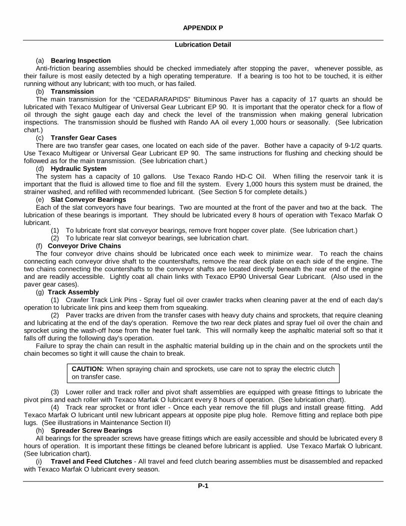
APPENDIX P
Lubrication Detail
(a) Bearing InspectionAnti-friction bearing assemblies should be checked immediately after stopping the paver, whenever possible, as
their failure is most easily detected by a high operating temperature. If a bearing is too hot to be touched, it is eitherrunning without any lubricant; with too much, or has failed.
(b) TransmissionThe main transmission for the “CEDARARAPIDS” Bituminous Paver has a capacity of 17 quarts an should be
lubricated with Texaco Multigear of Universal Gear Lubricant EP 90. It is important that the operator check for a flow ofoil through the sight gauge each day and check the level of the transmission when making general lubricationinspections. The transmission should be flushed with Rando AA oil every 1,000 hours or seasonally. (See lubricationchart.)
(c) Transfer Gear CasesThere are two transfer gear cases, one located on each side of the paver. Bother have a capacity of 9-1/2 quarts.
Use Texaco Multigear or Universal Gear Lubricant EP 90. The same instructions for flushing and checking should befollowed as for the main transmission. (See lubrication chart.)
(d) Hydraulic SystemThe system has a capacity of 10 gallons. Use Texaco Rando HD-C Oil. When filling the reservoir tank it is
important that the fluid is allowed time to floe and fill the system. Every 1,000 hours this system must be drained, thestrainer washed, and refilled with recommended lubricant. (See Section 5 for complete details.)
(e) Slat Conveyor BearingsEach of the slat conveyors have four bearings. Two are mounted at the front of the paver and two at the back. The
lubrication of these bearings is important. They should be lubricated every 8 hours of operation with Texaco Marfak Olubricant.
(1) To lubricate front slat conveyor bearings, remove front hopper cover plate. (See lubrication chart.)(2) To lubricate rear slat conveyor bearings, see lubrication chart.
(f) Conveyor Drive ChainsThe four conveyor drive chains should be lubricated once each week to minimize wear. To reach the chains
connecting each conveyor drive shaft to the countershafts, remove the rear deck plate on each side of the engine. Thetwo chains connecting the countershafts to the conveyor shafts are located directly beneath the rear end of the engineand are readily accessible. Lightly coat all chain links with Texaco EP90 Universal Gear Lubricant. (Also used in thepaver gear cases).
(g) Track Assembly(1) Crawler Track Link Pins - Spray fuel oil over crawler tracks when cleaning paver at the end of each day's
operation to lubricate link pins and keep them from squeaking.(2) Paver tracks are driven from the transfer cases with heavy duty chains and sprockets, that require cleaning
and lubricating at the end of the day's operation. Remove the two rear deck plates and spray fuel oil over the chain andsprocket using the wash-off hose from the heater fuel tank. This will normally keep the asphaltic material soft so that itfalls off during the following day's operation.
Failure to spray the chain can result in the asphaltic material building up in the chain and on the sprockets until thechain becomes so tight it will cause the chain to break.
CAUTION: When spraying chain and sprockets, use care not to spray the electric clutchon transfer case.
(3) Lower roller and track roller and pivot shaft assemblies are equipped with grease fittings to lubricate thepivot pins and each roller with Texaco Marfak O lubricant every 8 hours of operation. (See lubrication chart).
(4) Track rear sprocket or front idler - Once each year remove the fill plugs and install grease fitting. AddTexaco Marfak O lubricant until new lubricant appears at opposite pipe plug hole. Remove fitting and replace both pipelugs. (See illustrations in Maintenance Section II)
(h) Spreader Screw BearingsAll bearings for the spreader screws have grease fittings which are easily accessible and should be lubricated every 8
hours of operation. It is important these fittings be cleaned before lubricant is applied. Use Texaco Marfak O lubricant.(See lubrication chart).
(i) Travel and Feed Clutches - All travel and feed clutch bearing assemblies must be disassembled and repackedwith Texaco Marfak O lubricant every season.
P-1
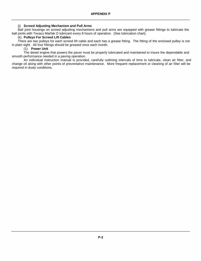
APPENDIX P
(j) Screed Adjusting Mechanism and Pull ArmsBall joint housings on screed adjusting mechanisms and pull arms are equipped with grease fittings to lubricate the
ball joints with Texaco Marfak O lubricant every 8 hours of operation. (See lubrication chart).(k) Pulleys For Screed Lift CablesThere are two pulleys for each screed lift cable and each has a grease fitting. The fitting of the enclosed pulley is not
in plain sight. All four fittings should be greased once each month.(1) Power UnitThe diesel engine that powers the paver must be properly lubricated and maintained to insure the dependable and
smooth performance needed in a paving operation.An individual instruction manual is provided, carefully outlining intervals of time to lubricate, clean air filter, and
change oil along with other points of preventative maintenance. More frequent replacement or cleaning of air filter will berequired in dusty conditions.
P-2
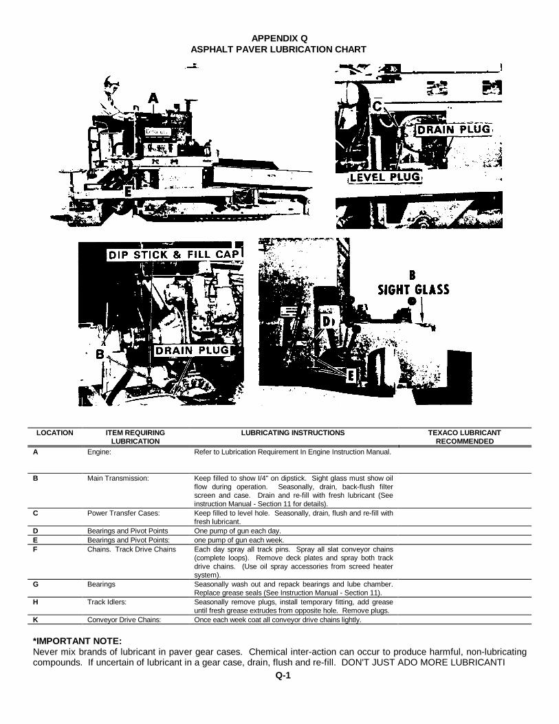
APPENDIX QASPHALT PAVER LUBRICATION CHART
LOCATION ITEM REQUIRINGLUBRICATION
LUBRICATING INSTRUCTIONS TEXACO LUBRICANTRECOMMENDED
A Engine: Refer to Lubrication Requirement In Engine Instruction Manual.
B Main Transmission: Keep filled to show I/4" on dipstick. Sight glass must show oilflow during operation. Seasonally, drain, back-flush filterscreen and case. Drain and re-fill with fresh lubricant (Seeinstruction Manual - Section 11 for details).
C Power Transfer Cases: Keep filled to level hole. Seasonally, drain, flush and re-fill withfresh lubricant.
D Bearings and Pivot Points One pump of gun each day.E Bearings and Pivot Points: one pump of gun each week.F Chains. Track Drive Chains Each day spray all track pins. Spray all slat conveyor chains
(complete loops). Remove deck plates and spray both trackdrive chains. (Use oil spray accessories from screed heatersystem).
G Bearings Seasonally wash out and repack bearings and lube chamber.Replace grease seals (See Instruction Manual - Section 11).
H Track Idlers: Seasonally remove plugs, install temporary fitting, add greaseuntil fresh grease extrudes from opposite hole. Remove plugs.
K Conveyor Drive Chains: Once each week coat all conveyor drive chains lightly.
*IMPORTANT NOTE:Never mix brands of lubricant in paver gear cases. Chemical inter-action can occur to produce harmful, non-lubricatingcompounds. If uncertain of lubricant in a gear case, drain, flush and re-fill. DON'T JUST ADO MORE LUBRICANTI
Q-1
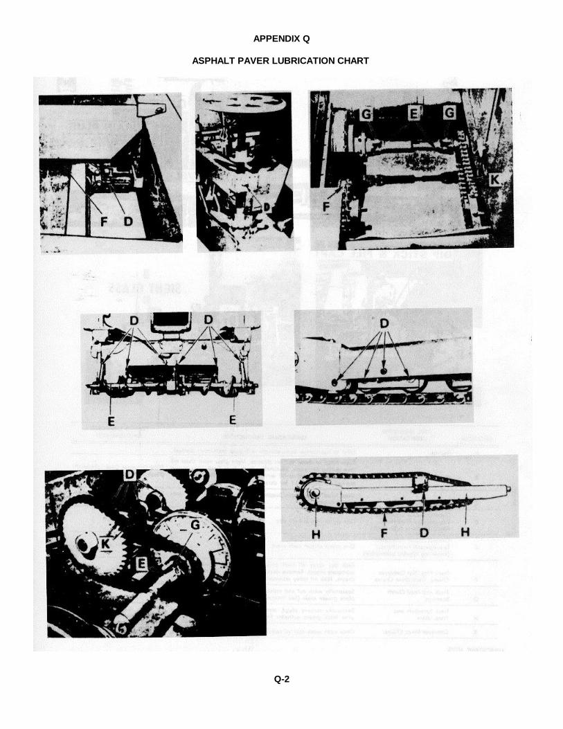
APPENDIX Q
ASPHALT PAVER LUBRICATION CHART
Q-2
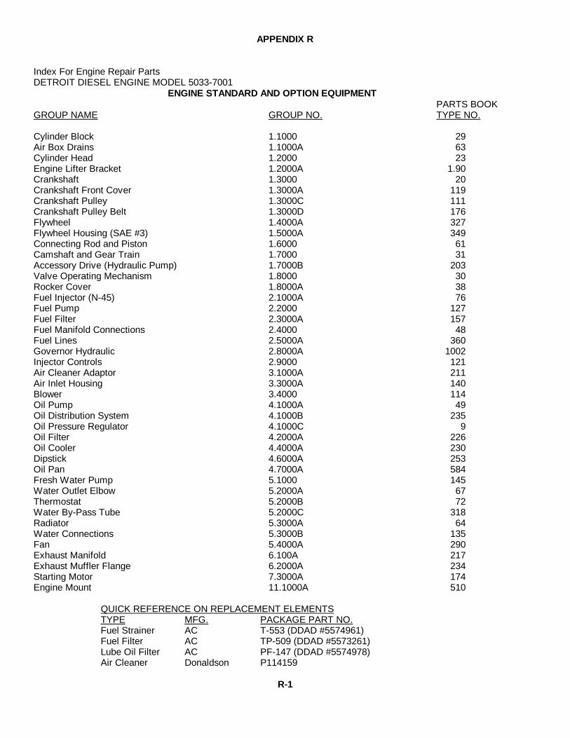
APPENDIX R
Index For Engine Repair PartsDETROIT DIESEL ENGINE MODEL 5033-7001
ENGINE STANDARD AND OPTION EQUIPMENTPARTS BOOK
GROUP NAME GROUP NO. TYPE NO.
Cylinder Block 1.1000 29Air Box Drains 1.1000A 63Cylinder Head 1.2000 23Engine Lifter Bracket 1.2000A 1.90Crankshaft 1.3000 20Crankshaft Front Cover 1.3000A 119Crankshaft Pulley 1.3000C 111Crankshaft Pulley Belt 1.3000D 176Flywheel 1.4000A 327Flywheel Housing (SAE #3) 1.5000A 349Connecting Rod and Piston 1.6000 61Camshaft and Gear Train 1.7000 31Accessory Drive (Hydraulic Pump) 1.7000B 203Valve Operating Mechanism 1.8000 30Rocker Cover 1.8000A 38Fuel Injector (N-45) 2.1000A 76Fuel Pump 2.2000 127Fuel Filter 2.3000A 157Fuel Manifold Connections 2.4000 48Fuel Lines 2.5000A 360Governor Hydraulic 2.8000A 1002Injector Controls 2.9000 121Air Cleaner Adaptor 3.1000A 211Air Inlet Housing 3.3000A 140Blower 3.4000 114Oil Pump 4.1000A 49Oil Distribution System 4.1000B 235Oil Pressure Regulator 4.1000C 9Oil Filter 4.2000A 226Oil Cooler 4.4000A 230Dipstick 4.6000A 253Oil Pan 4.7000A 584Fresh Water Pump 5.1000 145Water Outlet Elbow 5.2000A 67Thermostat 5.2000B 72Water By-Pass Tube 5.2000C 318Radiator 5.3000A 64Water Connections 5.3000B 135Fan 5.4000A 290Exhaust Manifold 6.100A 217Exhaust Muffler Flange 6.2000A 234Starting Motor 7.3000A 174Engine Mount 11.1000A 510
QUICK REFERENCE ON REPLACEMENT ELEMENTSTYPE MFG. PACKAGE PART NO.Fuel Strainer AC T-553 (DDAD #5574961)Fuel Filter AC TP-509 (DDAD #5573261)Lube Oil Filter AC PF-147 (DDAD #5574978)Air Cleaner Donaldson P114159
R-1

TM 5-3895-355-14&P
By Order of the Secretary of the Army:
E. C. MEYERGeneral, United States Army
Official: Chief of Staff
J. C. PENNINGTONMajor General, United States Army
The Adjutant General
Distribution:
To be distributed in accordance with DA Form 12-25B, Operator and Organizational Maintenance requirements for PaverBituminous.
* U.S. GOVERNMENT PRINTING OFFICE : 1993 O - 342-421/63427


PIN: 048084-000


![Detroit Diesel Catalog 2009[1]](https://static.fdocuments.in/doc/165x107/55cf9859550346d033972330/detroit-diesel-catalog-20091.jpg)

