DETERMINING THE MAXIMUM SPEED BORNE BY THE ELASTIC ... · the international conference of the...
5
THE INTERNATIONAL CONFERENCE OF THE CARPATHIAN EURO-REGION SPECIALISTS IN INDUSTRIAL SYSTEMS 7 th EDITION DETERMINING THE MAXIMUM SPEED BORNE BY THE ELASTIC STRUCTURE OF A MACHINE TOOL, PREVIONSTY ITS REMANUFACTURING Dinu DARABĂ 1 , Constantin DOGARIU 2 , Dorel Florea Anania 3 1 Associate Lecturer Eng. and Economist North University of Baia Mare, 62A Dr. V. Babeş street, Romania 2 Professor PHd. eng. University POLITEHNICA of Bucharest, 3 Lecturer PHd. University POLITEHNICA of Bucharest splaiul independentei 313. 1 [email protected] 2 [email protected], 3 [email protected] . Abstract: The finite element method is a numerical method used for solving the complex issues of engineering.. The method comprises of discreting the continuous environment through assemble of finite elements, which interact between them in a finite number of nodes. The interacting forces of the nodes of the model characterize the actions of the interior forces or stresses that are applied upon the contours of the neighboring elements. Key words: finit elements method, remanufacturing, modal analyses, vibration models 1. INTRODUCTION The finite elements method comprises of replacing the real structure (continuous) with an ideal structure (not continuous), divided or discreted into smaller subsets named finite elements. The continuous advance in computers technology paved the way for simulating the different components in exploitation mode, thus concurring to the decreasing or even totally eliminating the necessary costs of the prototypes making and research. The finite element method is a numerical method used for solving the complex issues of engineering. This method was applied for the first time more than 50 years ago and it was continuously developed, so today it is considered to be one of the best methods of efficiently solving a large variety of practical issues. 2.WORK STAGES The method comprises of discreting the continuous environment through assemble of finite elements, which interact between them in a finite number of nodes. The interacting forces of the nodes of the model characterize the actions of the interior forces or stresses that are applied upon the contours of the neighboring elements. So, calculating of a strength element which is considered as a continuous environment with an infinite number of connections has been reduced to calculating of a system with a finite number of connections or degrees of freedom. Discreting the structures can be carried out with linear, plane or spatial finite elements. The structures analysis imposes using two systems of reference [2]: One system which is associated to the structure – named global system – in which the position is defined and its movements are determined; One system which is associated to each element – named local system.
Transcript of DETERMINING THE MAXIMUM SPEED BORNE BY THE ELASTIC ... · the international conference of the...

THE INTERNATIONAL CONFERENCE OF THE CARPATHIAN EURO-REGION SPECIALISTS IN INDUSTRIAL SYSTEMS
7th EDITION
DETERMINING THE MAXIMUM SPEED BORNE BY THE ELASTIC STRUCTURE OF A MACHINE TOOL,
PREVIONSTY ITS REMANUFACTURING
Dinu DARABĂ1 , Constantin DOGARIU2, Dorel Florea Anania 3 1 Associate Lecturer Eng. and Economist North University of Baia Mare, 62A Dr. V. Babeş street, Romania 2Professor PHd. eng. University POLITEHNICA of Bucharest, 3Lecturer
PHd. University POLITEHNICA of Bucharest splaiul independentei 313. [email protected] [email protected], [email protected] .
Abstract: The finite element method is a numerical method used for solving the complex issues of engineering.. The method comprises of discreting the continuous environment through assemble of finite elements, which interact between them in a finite number of nodes. The interacting forces of the nodes of the model characterize the actions of the interior forces or stresses that are applied upon the contours of the neighboring elements. Key words: finit elements method, remanufacturing, modal analyses, vibration models
1. INTRODUCTION The finite elements method comprises of replacing the real structure (continuous) with an ideal structure (not continuous), divided or discreted into smaller subsets named finite elements. The continuous advance in computers technology paved the way for simulating the different components in exploitation mode, thus concurring to the decreasing or even totally eliminating the necessary costs of the prototypes making and research. The finite element method is a numerical method used for solving the complex issues of engineering. This method was applied for the first time more than 50 years ago and it was continuously developed, so today it is considered to be one of the best methods of efficiently solving a large variety of practical issues. 2.WORK STAGES The method comprises of discreting the continuous environment through assemble of finite elements, which interact between them in a finite number of nodes. The interacting forces of the nodes of the model characterize the actions of the interior forces or stresses that are applied upon the contours of the neighboring elements. So, calculating of a strength element which is considered as a continuous environment with an infinite number of connections has been reduced to calculating of a system with a finite number of connections or degrees of freedom. Discreting the structures can be carried out with linear, plane or spatial finite elements. The structures analysis imposes using two systems of reference [2]: One system which is associated to the structure – named global system – in which the
position is defined and its movements are determined; One system which is associated to each element – named local system.
One of the known coordinate systems: Cartesian, cylindrical or spherical, can be chosen as systems of reference. Finite elements of square linear type, stressed within the local plane (q, k), with two degrees of freedom on every node were used, in order to discrete the analyzed structure. The approximation function of movements (u,v) is as it follows [3]:
4
4
3
3
2
2
1
1
4321
4321
0000000
vuvuvuvu
NNNNONNNN
vu
(1.1)
The interpolation functions used in the calculus have the following form [112]:
411
1qkN
for node D; 411
2qkN
for node C;
(1.2)
411
3qkN
for node B; 411
4qkN
for node A .
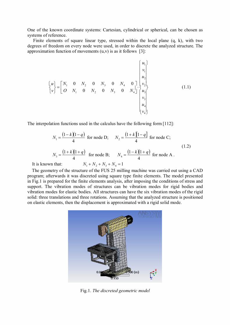
It is known that: 14321 NNNN The geometry of the structure of the FUS 25 milling machine was carried out using a CAD program; afterwards it was discreted using square type finite elements. The model presented in Fig.1 is prepared for the finite elements analysis, after imposing the conditions of stress and support. The vibration modes of structures can be vibration modes for rigid bodies and vibration modes for elastic bodies. All structures can have the six vibration modes of the rigid solid: three translations and three rotations. Assuming that the analyzed structure is positioned on elastic elements, then the displacement is approximated with a rigid solid mode.
Fig.1. The discreted geometric model

Fig.2 shows the conditions of fastening and stress for the analysis of the structure behavior to static stress (the force 2F = 2598 N has its application point on the case of the main shaft, and the force that actions on the machine table has the value of F = 2000 N). The structure is freed from bonds, in the finite elements modal analyses. The first six own frequencies, relative to the six degrees of freedom of the structure (three translations and three rotations) are not taken into account. The structure analysis begins from the 7th own frequency.
Fig. 2. Mode of fastening and stress The first own frequencies obtained by theoretic analysis are low. For example, the frequency of 4.6 Hz, according to Fig.3, is a false frequency that can be corrected by stiffening the table support, as from the analysis it is found that the table support can be broken at this frequency. The 112.3 Hz own vibration, Fig.4 – leads the machine tool to a resonance state that contributes to displacements of the machine structure elements, severely affecting the processing accuracy. A rotation of the machine body and table around the Z axis but in contrary directions is noted in Fig.4, leading to the modification of the position of the tool against the processed part.
Fig.3.Movements of the structure Fig.4. Movements of the structure by f = 4,6 Hz by = 112 Hz

The own mode presented in Fig.5 at the frequency of 140,84 Hz marks out a bending of the machine body and table within the X-Z plane, catastrophically affecting the tool-part position. The theoretical frequency obtained by modal FEM analysis were validate by experimental data acquisition (fig.6) with a Schenk Vibroport 41 (fig.7) [5] from the National Research Centre for Performances of Technological Systems – Optimum (http://sun.cfic.pub.ro
Fig .5. Movements of the structure by f = 140Hz.
Fig.6. Transfer function experimental data acquisition
Fig.7. Vibroport 41
The resonance danger does not appear anymore from the 112 Hz own frequency of the analyzed structure, as the subsequent frequencies are off the domain of the work frequencies. In the view of this analyses, it can be asserted that the own frequency that imposes the maximum value of the remanufactured machine speed is 112 Hz. The relation (1.6) is used for the calculation of the maximum speed that can be attained after the remanufacturing process, thus[3]:
60
min/22/ crotNHzvsradc
(1.3.)
Assuming that the processing speed is:
rotmmfsradrotmmfrotNmmv c //260/min/min/a
(1.4.)
Making the reduction, it results that :
sradrotN c /260min/
(1.5.)
But: fc 2 , then: fN 60 [rev/min] (1.6) Thus the maximum speed will be 6700 rev/ min. 3.CONCLUSIONS
In order to set up a methodology of assessing the dynamic performances of the remanufactured machine tools, previously from commencing their remanufacturing, we chose a milling machine for the theoretic research, as the milling process is a procedure of generating the surfaces, which is highly generating forced vibrations. The dynamic aspects met by the milling machines can be considered as covering for most of the machine tools.
The results of the research should contribute to obtain a valid analytical model that is to characterize the future dynamic behavior of the remanufactured technologic equipment, and which is to offer information that are less evident in the design stage of remanufacturing. 4. REFERENCES [1]. Darabă, D., Analyses of technological equipment structural elements for remanufacturing using the finite element method, microCAD 2008 Inter. Scientific Conference. Machine and Construction Design, University of Miskolc, 2008. [2]. Mogan, Gh. L., Metoda elementelor finite în inginerie, Editura Lux Libris, Braşov, 1997. [3]. Moraru, V.,Ghionea, A., Predincea, N., Aurite, T., Enciu, G., Nicolescu, A., Dogariu, C., Teoria şi proiectarea maşinilo-unelte. Îndrumar de proiectare, Partea a III-a, Litografia I. P. Bucureşti, 1987. [4] Moraru, V., Ispas, C., Rusu, St., Vibratiile si stabilitatea Masinilor-Unelte, Editura Tehnica, Bucuresti, 1982. [5] Ispas, C., Bausic, F., Zapciu, M., Parausan, I., Mohora,C., Dinamica masinilor si utilajelor, Ed. AGIR, bucuresti, 2008 [5]. http://sun.cfic.pub.ro