Determining Corrective Action for Highway Landslide...
27
Determining Corrective Action for Highway Landslide Problems R. F. BAKER, Engineer of Soil Mechanics State Road Commission of West Virginia THE PROBLEM of landslides has plagued highway departments throughout the country for many years. For some states, and particularly West Virginia, the dam- age caused by earth movements represents a major expenditure, one that involves hundreds of thousands of dollars annually. Over 80 percent of the area of West Virginia is located in a landslide-sus- ceptible area. The total number of landslides on the state highways has never been established. However, the writer estimates that this total will approach 1,000 on the 31,000 miles of primary and secondary roads in the state. The complexities of the landslide prob- lem have very few parallels in highway engineering. The literature on the subject carries numerous references to case histories, but none outlines a systematic, complete approach to the solution of a given problem. The recent bibliography published by the Highway Research Board (1) offers a complete summary of the publications relative to mass movements. The work of geologists on landslides has been and is of considerable value. The classification systems suggested by Sharpe (2) and Ladd (3) assist tremen- dously m understanding the complicated variety of movements that occur. From the viewpoint of corrective actions, the report by Ladd is perhaps the most com- prehensive contained in the landslide literature. Numerous engineers (4, 5, 6,7,8,9,10,11,15) have discussed the application of the theories of Soil Me- chanics to the analysis of the stability of a landslide, but there are few details concerning the determination of the effect of a corrective action in terms of stability. The study that led to the following theory was designed to prepare an ap- proach to the analysis and correction of highway problems dealing with land- slides in unconsolidated materials. The primary emphasis was to be towards the correction of existing problems. How- ever, it was felt that the principles should be applicable to the problem of design. The basis for the study was the writ- er's experiences in West Virginia, com- bined with general theories from geology, soil mechanics, and highway engineering. The analysis as advanced is for consider- ation in the study of ail landslides in unconsolidated material, with the ex- ception of those of the nature of fluvial transported material, i. e., the water present is far in excess of normal soil moisture, and the debris is a "relatively small proportion of the flowing mass" (2). Since one of the primary aims of the study was to consider the applicability of the various corrective measures, the investigation could have been accomplish- ed by a study of existing landslides that have been treated. Such an approach was used by Price and Lilly (12) in 1942. However, a direct study was impossible since as a routine department function there were requests to investigate over 100 landslides during the past three years. Due to a personnel shortage, the demand necessitated superficial analyses but it was decided that the program lent itself to the development of aprocedureto evaluate the movements. In addition, it became possible to study the applicability and usefulness of various corrective methods. The theories ad- vanced in the following are not complete for three vital factors remain in the evaluation: (1) observation of those landslides that have been corrected by the methods outlined herein; (2) a more comprehensive study of flow movements.
Transcript of Determining Corrective Action for Highway Landslide...

Determining Corrective Action for Highway Landslide Problems
R. F . B A K E R , Engineer of Soil Mechanics State Road Commiss ion of West V i r g i n i a
T H E P R O B L E M of landslides has plagued highway departments throughout the country for many years . F o r some states, and part icular ly West V i r g i n i a , the damage caused by earth movements represents a major expenditure, one that involves hundreds of thousands of dol lars annually. Over 80 percent of the a r e a of West Virg in ia i s located in a lands l ide-susceptible area . The total number of landslides on the state highways has never been established. However, the wri ter estimates that this total w i l l approach 1,000 on the 31,000 mi les of pr imary and secondary roads in the state.
The complexities of the landslide probl e m have very few para l l e l s in highway engineering. The l i terature on the subject c a r r i e s numerous references to case h is tor ies , but none outlines a systematic , complete approach to the solution of a given problem. The recent bibliography published by the Highway R e s e a r c h Boar d (1) offers a complete summary of the publications relative to mass movements. The work of geologists on landslides has been and i s of considerable value. The c lass i f icat ion systems suggested by Sharpe (2) and Ladd (3) a s s i s t t remendously m understanding the complicated variety of movements that occur. F r o m the viewpoint of correct ive actions, the report by Ladd i s perhaps the most c o m prehensive contained in the landslide l i terature. Numerous engineers (4, 5, 6 , 7 , 8 , 9 , 1 0 , 1 1 , 1 5 ) have discussed the application of the theories of Soil M e chanics to the analys is of the stability of a landslide, but there a r e few details concerning the determination of the effect of a correct ive action in terms of stability.
The study that led to the following theory was designed to prepare an approach to the analys is and correct ion of
highway problems dealing with landsl ides in unconsolidated mater ia l s . The p r i m a r y emphasis was to be towards the correct ion of existing problems. However , it was felt that the pr inc iples should be applicable to the problem of design.
The bas is for the study was the w r i t e r ' s experiences in West V i r g i n i a , c o m bined with general theories f rom geology, soi l mechanics , and highway engineering. The analys is as advanced i s for cons ideration in the study of a i l landslides in unconsolidated mater ia l , with the exception of those of the nature of f luv ia l transported mater ia l , i . e . , the water present i s far in excess of normal so i l moisture, and the debris i s a "relatively s m a l l proportion of the flowing mass" (2).
Since one of the p r i m a r y a i m s of the study was to consider the applicability of the var ious correct ive measures , the investigation could have been accompl i shed by a study of existing landslides that have been treated. Such an approach was used by P r i c e and L i l l y (12) in 1942. However, a direct study was impossible since a s a routine department function there were requests to investigate over 100 landslides during the past three years . Due to a personnel shortage, the demand necessitated superf ic ia l analyses but it was decided that the program lent itself to the development of aprocedureto evaluate the movements. In addition, it became possible to study the applicability and usefulness of var ious correct ive methods. The theories a d vanced in the following are not complete for three vi tal factors remain in the evaluation: (1) observation of those landslides that have been corrected by the methods outlined herein; (2) a more comprehensive study of flow movements.

-SL IP SURFACE MO SUP SURFACE
Figure 1. D i f f erent ia t ion between s l ide and flow ( a f t e r Sharpe) . A s l i d e i s a movement of a block of material , whereas flow i s e n t i r e l y i n t e r n a l deformation.
and (3) investigation of l e s s costly methods for correct ing landslide problems.
The wr i ter is aware that the analys is i s an over-s impli f icat ion. Extensive study and evaluation is s t i l l very neces sary , but for the immediate future a working tool i s available.
D E F I N I T I O N S
The following definitions w i l l be used throughout. Some of the terms may be argumentative and general , but it i s the opinion of the wri ter that the following are most applicable to the engineering phases of the landslide problem.
Landsl ides have been defined by Terzaghi (3) as follows: "The term landslides re fers to a rapid displacement of a mass of rock, res idual so i l , or settlement adjoining a slope in which
the center of gravity of the moving mass advances in a downward and outward direction. " It w i l l be noted that the time element is involved in the definition only by the term "rapid displacement. "
The terms sl ip-plane, s l ip - sur face , and surface of fai lure wi l l be synonymous and wi l l re fer to the surface that separates the mass in motion f rom the underlying stable materia l .
Permanent solutions w i l l be defined as corrections with an anticipated life of at least 50 years . An expedient so lution wi l l be considered adequate for a period of a few months to 5 to 10 years .
A l l correct ive actions wi l l be c lassed as one of two types, elimination or control . The actions involving elimination depend generally upon avoiding or r e moving the landslide. Control methods are defined as correct ions which produce a static condition of the landslide for a finite period of time.
While there have been many c l a s s i f i c a tion systems proposed, the bases for the c lass i f icat ions have most generally been related to cause and effect of the movement rather than the mechanics. One notable exception is the system proposed byHennes (7). F o r a quantitative analys is of a design or correct ion for a given landslide, the most satisfactory c l a s s i f i -
Figure 2. A definite sl ip-plane, identifying the movement as a s l ide .
cation is one which differentiates on a basis of the effect of the forces and res is tances at work. Thus , the major pr imary c lass i f icat ion would appear to be landslides in consolidated mater ia ls , and those in unconsolidated materials . A second p r i m a r y differentiation would divide the movements into those with a s l ip -surface and those without a s l ip -surface. T h i s latter grouping was outlined by Sharpe (2), who termed the former as s l ides and the latter a s flows. The principle is pictured in F igure 1. The movements in flow conditions are the result of internal deformations.
3
s tressed beyond their "fundamental strengths," and as a result , slow but constant internal deformations occur.
B A S I C F U N D A M E N T A L S IN L A N D S L I D E A N A L Y S E S
F r o m the observation of landslides in West V i r g i n i a , and from a review of the l i terature on landslides and so i l mechanics , the following statements have been outlined by the wri ter (13) as being fundamental to the analys is of a landslide relative to its correct ion as a highway problem. It should be empha-
i
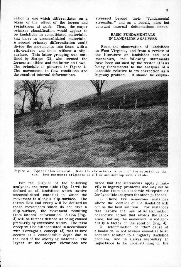
Figure 3. Typical flow movement. Note the character is t ic rol l of the material at the toe. Some movements originate as a flow and develop into a s l ide .
F o r the purpose of the following analyses , the term slide (Fig . 2) wi l l be defined as a l l landslides which involve unconsolidated material in which the movement is along a s l ip - surface . The terms flow and creep w i l l be defined as those movements which do not have a s l ip - surface , the movement resulting from internal deformation. A flow (F ig . 3) w i l l be further defined as being caused p r i m a r i l y by excessive water. The term creep w i l l be differentiated in accordance with Terzaghi ' s concept (3) that fai lure occurs at a considerable depth due to the load of the overlying material . The layers at the deeper elevations a r e
s ized that the statements apply p r i m a r i ly to highway problems and may not be of value from an academic viewpoint or for landslide analyses for other purposes.
1. There are numerous instances where the control of the landslide wi l l not be the best solution. F o r instances that involve the use of an elimination correct ive action that avoids the landsl ide, halting the movement i s not general ly a factor in the solution (F ig . 4).
2. Determination of "the" cause of a landslide is not always essent ial to an accurate solution to a highway landslide problem, and is always secondary in importance to an understanding of the

/ Figure 4. The sl ide involved in the pictured location i s at the right. Tlie problem was solved by shi f t ing the roadway into the stable bedrock at the l e f t of the picture.
mechanics of the movement. The cause of a landslide i s often argumentative even after a l l the available facts have been determined. In many cases , one cause or another may have been the straw that broke the camel 's back. Of more importance than the cause , i s the realization that increased stability wi l l result by eliminating or minimizing the effect of any contributing factor, p a r t icularly that of the effect of the force of gravity.
3. The works of man can measurably accelerate or decelerate the rate of movement of a landslide toward the topographic bottom of the area . L a n d sl ides are recognized by geomorpholo-gists as being a major landforming p r o c ess . The most permanent solutions to control the mass movement wi l l be those of a type that permanently (from a geologic viewpoint) a s s i s t nature's res istance.
4. F a i l u r e occurs in the so i l when the sl ip-plane i s at the contact with the underlying stable bedrock. T h i s observation i s val id for a l l of the instances studied in West V irg in ia , and was mentioned by Forbes (14) as having been noted in Cal i fornia . Thus , the shear character i s t i c s of the so i l at the s l i p -
surface become of pr imary interest (Fig . 5).
5. F o r a given landslide problem there i s more than one method of c o r rection that can be successful ly applied. A common misconception that should be c lear ly dispelled is that for a given landslide there i s one and only one solution. The inference that is undoubtedly intended i s that for any given landslide, one method i s the most desirable from a cons ideration of economics, appearance, construction problems, etc.
6. The decision as to the correct ive action to be used for a given highway landslide problem is eventually reduced to a problem of economics. T h i s i s a statement of an obvious fact, but it i s too often subjugated to other considerations. An example that i l lustrates the point in question would be the case of retaining walls . A wal l can be designed sufficiently large to withstand any given landslide. However, a wal l design that wi l l be success fu l may be outside a reasonable range of the economics for a given landslide.
7. Water is a contributing factor in pract ical ly a l l landslides, part icular ly those involving unconsolidated mater ia l s .

Aside from the force of gravity, no factor is more generally present as a contributing factor. The damaging a c tion results from the added weight to the m a s s , the reduction of shear c h a r a c ter i s t i c s of the soi l and underlying bedrock (14). Some investigators also state that water produces a lubricating action on the sl ip-plane. T h i s latter would appear to be a rather unlikely explanation, at least insofar as the mechanics of lubrication are generally accepted.
8. The force of gravity i s the sole contributing factor that i s common to a l l landslides. The most obvious bas is for a rational analys is i s the fact that the force of gravity i s the source of a l l forces tending to cause movement. Until these forces are understood and evaluated, empir i ca l methods are the only available approach.
9. In a l l mass movements, and just p r i o r to movement, the reactions tending to re s i s t movement are for a l l prac t i ca l purposes equal to the forces tending to cause movement. The foregoing statement is an irrefutable fact if the laws of
mechanics are val id. F a i l u r e to s a t i s factorily apply a theoretical formula merely means that the method for eva l uating the force and the res is tance i s inadequate. T h i s fact i s important since it c lear ly defines the troublesome f ea tures in a rational approach to the mechanics of landslides.
10. The determination of the location of the s l ip -surface i s the most c r i t i c a l factor in the use of a rational or s e m i -rational approach. Experience has shown that one of the principal l imi ta tions on the use of a theoretical approach is the accurate determination of the location of the s l ip - surface . The problem is involved in both a theoretical office approach and in f ie ld examinations. The latter problems are largely due to the lack of a rel iable tool that wi l l rapidly, accurately and inexpensively produce the desired subsurface data.
C L A S S I F I C A T I O N O F C O R R E C T I V E M E A S U R E S
In order to c lar i fy the analys i s , a
Figure 5. The slip-plane developed approximately 1 in . above a layer of stable shale. The scar at the l e f t of the picture developed as the thin layer of clay dried and
cracked. '

6
c lass i f icat ion was suggested for various correct ive measures commonly used in highway landslide problems. It w i l l be r e cal led that the fundamental difference l ies in whether the method involves elimination or control. The following i s a detailed c lass i f icat ion of the most common c o r rective measures currently in use. The bas is of the c lass i f icat ion i s the s imi lar i ty of the analyses within a given group. More details on the methods a r e given in Appendixes B , C , and D.
I . El iminat ion methods A. Relocation of structure -
complete B . Removal of the landslide
1. E n t i r e 2. P a r t i a l at toe
C . Bridging D. Cementation of loose mater ia l -
entire n . Control methods
A. Retaining devices 1. But tresses
a. Rock b. Cementation of loose
mater ia l at toe c. Chemica l treatment -
flocculation - at toe d. Excavate , drain and
backf i l l at toe e. Relocation - r a i s e grade
at toe f. Drainage of the toe
2. Cribbing - concrete, steel or timber
3. Retaimng wal l - masonry or concrete
4. P i l ing - steel , concrete or timber
a. Floating b. F i x e d - no provision for
preventing extrusion c. F i x e d - provision for
preventing extrusion 5. Tie-rodding slopes
B . D irec t rebalance of the ratio between res is tance and force
1. Drainage a. Surface
(1) Reshaping landslide surface
(2) Slope treatment b. Subsurface (French drain
type)
c. Jacked- in-place or dr i l led - in-place pipe
d. Tunnelling e. Blast ing f. Sealing joint planes and
open f i s s u r e s 2. Removal of mater ia l -
part ial ly at top 3. Lightweight f i U 4. Relocation - lower grade at
top 5. Excavate , dra in , and backf i l l
- entire 6. Chemica l treatment -
flocculation - entire
P R E L I M I N A R Y A N A L Y S I S O F A L A N D S L I D E
The foregoing i s a lengthy l i s t of methods that have been used s u c c e s s fully in controlling or avoiding landslides. L a d d (3) suggested most of those that appear in the classification^ The c o m plete l i s t of possibi l i t ies should be cons idered for each landslide at the start of the analys is .
Four factors are required before one can obtain an understanding of the mechanics of the stability of a landslide. These are:
1. The type, character , and topographic description of the underlying, stable bedrock or soi l .
2. The location of any seepage s trata that are leading into the landslide area .
3. The topography of the ground surface on and adjacent to the landslide. T h i s would include the accurate locationing of the moving area .
4. The types, cha ra c t er i s t i c s , and condition of the so i l in and adjacent to the moving area .
Before beginning a detailed f ie ld study, a pre l iminary analys is wi l l be helpful. The pr incipal objectives of these ini t ia l f ie ld and office studies a r e to c la s s i fy the movement, to determine the extent of the movement, to determine the need and scope of additional study, and to determine the probable methods of correct ion that wi l l be feasible.
Fortunately for the highway engineer, numerous landslides can be handled by elimination methods, i . e . , the landslide can be avoided or removed. In such

Figure 6. Drilling will occasionally produce excellent evidence of the location of
the slip-plane.
c a s e s , a rapid estimate of the costs involved wi l l show c lear ly the relative economics and general desirabil i ty of an elimination method. F o r those landslides that cannot be typed as one to be e l i m inated, an estimate is necessary a s to what types of control methods are within reason. With experience, it w i l l become increasingly eas ier to estimate the c o r rective methods that wi l l be most economical and otherwise desirable. A study of the appendixes that follow wi l l give some indication of the most desirable set of conditions for the various types of correct ive measures . The advantage to this init ial estimate l ies in the savings that can be rea l ized in future f ie ld and office analyses .
F I E L D S T U D Y
Where the situation permit s , the f ie ld study should extend over s evera l months and, in some c a s e s , years . Unfortunately, many highway problems w i l l require an ear ly decision, and extreme effort w i l l be required to delay action until even a superf ic ia l analys is can be made. A study that extends over s e v e r a l months differs p r i m a r i l y from a short study in that continuous observations are made of the direction and the extent of the movement, and of the fluctuation of the ground-water table.
The details to be obtained from the f ie ld study wi l l depend upon whether a complete analys is has been deemed necessary. F o r instance, for certa in types of landslides and retaining dev i c e s , only the foundation conditions of
the retaining device wi l l be needed. A s a general rule , however, if a stability ana lys i s i s necessary , it w i l l be d e s i r able to obtain the complete information indicated in the pre l iminary analys is .
In obtaining data concerning the subsurface conditions within the moving m a s s , various types of dri l l ing a s wel l as geophysical surveys have been used. The most important data to be obtained from this subsurface work are: (1) evidence of the location of the s l i p - s u r face (F ig . 6); (2) the condition of the so i l a s to moisture, density, and s t r u c ture (for future shear tests); and (3) information that indicates direction and type of movement.
S T A B I L I T Y A N A L Y S I S
The following stability ana lys i s i s a composite of numerous methods that appear in the l i terature, and i s proposed for use in a l l landslides involving unconsolidated materia l . It should be pointed out, however, that applicability of the stability computations to flow and creep movements w i l l require more study, part icular ly with regard to the location of the potential s l ip surface . However, by increas ing the o v e r - a l l stability (as indicated by a stability analys i s ) , the actual tendency for flow movement should be lessened.
It i s relatively easy to select a c o r rective measure that wi l l produce a beneficial effect on the landslide area . The purpose of the following analys i s i s to estimate the degree of stability p r o duced by a given method. In addition, the relative meri t s and costs of s evera l
OouM turtoe. otNr
O m I 2,3,«,"« S t«ptti«il poMkil Hip phuwi.
Figure 7. Slide that developed when the toe was cut. Core-drilling located underlying bed-rock. Curves 1 and 2 were established by theoretical formulae. Curves 3, 4, and 5 were adjusted due to layers oif
underlying stable material.

8
methods are studied. It i s assumed that the res is tance to movement equals the force causing movement at the i n stant of fa i lure . F o r m u l a s developed for use in the theoretical so i l mechanics are used in the evaluation. Since a l l of the correct ive measures which are considered are analyzed by the same method, the same relative stability should be obtained. The major point of concern i s whether the analys i s p r o duces an over-design or occasionally an under-design.
Stability analyses of landslides have been applied in two pr inc ipal ways. If the shear character i s t i c s of the so i l are determined, it i s possible to estimate the safety factor of the slope. A second procedure is the determination of the average cohesion, or c of the so i l at the s l ip - surface . With the latter method, laboratory tests a r e not used to determine the shear charac ter i s t i c s of the soi l . In either method, it i s most des irable to evaluate the landslide under the conditions which existed before the most recent movement. After the determination of the safety factor or the estimation of the shear character i s t i c s of the so i l mass , sufficient data are available to estimate the influence of the correct ive action.
The method used in West V irg in ia cons i s t s of the procedure involving the estimate of the average c and the following discussion deals p r i m a r i l y with this type analys i s . The f i r s t step in the stability
Figure 8. With homogeneous soil, the slip-plane would tend to develop along Curve A. I f the area i s underljid by bedrock (as shown in the shaded area) the slip-surface would tend to be as indicated by Curve B. I f the bed-rock lies as shown in the solid line, the slip-plane will lie approximately
in the position of Curve C.
Figure 9. llie presence of a weak soil layer will tend to produce a failure within i ts limits. On occasions, the actual slip-surface will be as close to the theoretical position indicated, and the circle can be
used in the computations.
computations i s to prepare typical c r o s s -sections para l l e l to the direction of movement (F ig . 7). The sections should be continued above and below the landslide. On these sections should be plotted a l l d r i l l information, resul ts of laboratory soi l tests , data concerning seepage strata , location of underlying bedrock, surface c r a c k s , s tructures , and any i n formation considered descriptive of the slide movement. The ground lines both before and after recent movements are very desirable. If the before-movement ground surface i s not known, a reasonable estimate wi l l be helpful. The most dangerous sections should then be s e lected for the init ial study. T h i s section w i l l generally be near the middle of the s l ide , w i l l have the greatest o v e r - a l l slope (from toe to top), and the greatest mass of unconsolidated mater iaL
The next step i s the most troublesome, and perhaps the most vital . The s l i p -plane must be drawn in its most probable location. The top and bottom of the slide a r e generally easi ly identified, but the intermediate portion w i l l c a l l for care fu l interpretation of the d r i l l data. O b s e r v a tions throughout the past years have led so i l engineers to the conclusion that slopes in homogeneous soi l s f a i l along surfaces that can be approximated by a c i r c l e (in a two-dimensional analys i s ) . Having the top and bottom of the landsl ide, two points near or on the s l i p -surface are known. The third, and controll ing, point must be estimated. T h e oret ica l formulas (5) suggest a method for the imt ia l approximation. These formulas are for slopes without s u r -

9
Slability equation: Sofely Foctor . S^Cg inQ Rtmtpnct . I N I o n ^ ^ - c t ,
I T • Sommotion of tongenlioJ components. ZN - Summotion of normol componentj.
L • Length of slip surfoce. To determine overoge V at failure - assume # ona use computed values tor other voriobles °
EG • Weight of increment ABCD EF • Tangentiol component of EG. FG - Normal component of EG
,^Sondstone ^
Figure 10. Solution by graphical integration. Tlie total area i s divided into i n crements of the same width as ABCD. Weight of the so i l i s computed and graphica l ly resolved into i t s tangential and normal
components.
charge and for homogenous mater ia ls . However, for the initial approximation, the formulas w i l l be of ass istance. The presence of an underlying, f i r m layer may effect a change in the location of the s l ip - surface . The change might result in a c i r c l e tangent to the layer , two c i r c l e s connected by a third c i r c l e , or two c i r c l e s connected by a straight line (F ig . 8). The shape of the s l ip - sur face
wi l l also be affected by the presence of weak layers (Fig . 9). Tay lor (8) has suggested that a c i r c l e that approximates a ser i e s of curves wi l l be sufficiently accurate.
The d r i l l data wi l l indicate the p r e s ence of underlying bedrock or stable so i l l ayers that are in a position to affect the s l ip-surface . In addition, l ayers of part icular ly weak soi l can be identified. If there is a question as to the position of the s l ip - sur face , a complete design should be made for each possibil i ty, and the s l ip -surface that produces the most conservative result should be used.
When the landslide is extensive, s l ip -planes must be checked for various points up and down the slope (F ig . 7), in addition to the o v e r - a l l stability. In some cases , s evera l s l ip-planes w i l l appear reasonable. E a c h of these should be checked as outlined in the following.
With a reasonable estimate as to the location of the s l ip - sur face , the c r o s s -section of the landslide should be divided into increments , para l l e l to the d i r e c tion of movement. Referr ing to Figure
Figure 11. Photograpli of roadway in Kanawha County near Charleston, West Virg in ia . Note break at right edge of picture.

10
10, A B C D i s a typical increment. The width of the increment i s dependent upon the i rregular i t i e s of the ground surface. General ly , an increment width of 10 to 30 ft. w i l l produce results we l l within the accuracy of the remainder of the analys is . The weight of the so i l in the increment i s computed, keeping in mind that the section is assumed to be 1 ft. in width (perpendicular to direction of movement). The weight should be computed for both the original ground surface and the ground surface after movement.
The weight may then be represented by a vector, i . e . , a scaled length representing the weight (Line E G ) . G r a p h i c a l resolution of this force i s accomplished by drawing a line tangent to the centerpoint of the segment of the s l ip -surface (Line E F ) . Another line is drawn perpendicular to the tangent at the midpoint of the s l ip - surface (Line F G ) .
The intersection of the two l ines defines their length. The p a r a l l e l force i s the shear , and the perpendicular force i s termed the normal . The resolution
of the forces i s accomplished for each increment of weight, and the sums of the shear forces (IT) and the normal forces ( 2 N ) are computed.
The forces tending to hold the so i l mass in place are (1) the fr ict ional c o m ponents of the normal forces and (2) the cohesion c of the so iL The forces tending to cause movement are those of shear , seepage, and hydrostatic p r e s sures . There i s a diversity of opinion as to the validity of neglecting these latter two forces . Under certa in conditions, the hydrostatic forces can be very significant, part icular ly in case s where cohesionless l ayers or pockets a r e present. The effect of the hydrostatic p r e s s u r e i s to reduce the normal forces , and in cohesive so i l s with a low 0 value, the change may be insignificant. The seepage forces tend to decrease the normal force as well as to increase the shearing force and the result i s s igni f i cant in the opinion of T a y l o r (8). I n the init ial stability analys i s , that follows, hydrostatic and seepage forces are neglected, except in their combined effect at
Figure 12. Same slitte as that in Figure 11. The toe of the movement i s in the middle of the picture.

11
the time of fai lure. A formula that has been proposed for
estimating the stability of a slope i s the following:
locolkm of timrbit M e t
Safety factor =2N tan < + c L ' - I T (1)
w h e r e I N = the summation of the normal forces in pounds S T = the summation of the shear forces in pounds 0 = the angle of internal fr ict ion c = cohesion in pounds per foot L = length of the s l ip - surface in feet
SlvUm locoM br (II Opa ends In treuml mrtao 01 Urn 16 a OMaa toKKt dlsplociiiioi oi lino 0 (9 Cora inmt nconlad bvlracli ot Imoi 4,12, ond 19
II 12 13 Gfoum «ot<r IIIM
'AppradmoM IIM 01 M n c k eolnddot •l lh nip plona bomon linto 3 and 16
Figure 13. Cross-section of the slide pictured in Figures 11 and 12. The slide has been divided Into increments and the computation of 2T and 2V is given m Table 1.
Assuming the landslide i s at the point of equil ibrium between movement and stability (safety factor = 1.0), the following form of the equation i s usefuL
Shearing force = shearing res is tance or
IT = 2N tan 0 + c L (2)
It w i l l be noted that the left side of Equation 2 represents the shearing forces causing movement, and the right side i s the shearing resistance to movement.
Thus f a r , the method for obtaining T and I N have been indicated. The values of 0 and c can be determined by shear or unconfined compression tests in the laboratory if desired. Except in r a r e instances, the laboratory values w i l l not produce a value of 1.0 for the safety factor (Equation 1). T h i s w i l l be true due to i rregular i t i e s in the so i l , to the d i f f i cult ies in obtaining undisturbed samples , to the problems of laboratory techmque,
R.-IT-(INton».a.l l%.|5IT-CNIon».cU •VFOsiiltonl ol forcit
octing ot ttcllon X-X Og-HnMan of fomt to bo
d«il«nod to ocl ol aootlon X - X t o t
Figure 14. Method for computing the forces acting at a given point in a slide. The valueof Tand N is determined for the area desired (from X-X to top in this sketch). The difference between the forces causing movement (IT) and the resistance to movement (7N tan <p + cL) is designated as Ry . The resistance that will produce a safety
factor of 1 . 5 is designated as RQ.
and probably to the effect of hydrostatic and seepage forces . Slopes in nature have been known to be stable even though the safety factor was computed as 0. 75. T h i s latter figure would indicate that the shearing res is tance was only 75 percent of the shearing force. If the safety factor for a stable slope i s l e s s than 1. 0, or if greater than 1. 0 for an unstable slope, it appears certa in that some factor has been disregarded. Numerous examinations have been made of landslide a r e a s , and the computed safety factor was greater than 1. 0. Indications were that such computations were based on conditions after the movement. Quite obviously, an area that has moved to a temporari ly stable position w i l l show a higher safety factor than 1.0 in its new position. It would appear to be pract ica l ly impossible to measure the conditions that exist at time of fai lure. However, if the s tar t ing point for the analys is i s the ground line pr ior to movement and Equation 2 i s used, the effects of these troublesome variables are accounted for a s a part of <t> or c.
F o r the following analys is of the s ta bility an estimate i s made of the value of <p. F r o m Equation 2 it i s then possible to compute the average c value needed to obtain an equality between the s h e a r ing forces and the shearing res is tance . If possible, computations should be c a r r i e d out for the ground surface con-
12
ioimABCbMan «g Sg- Unit Might of rock In buttnn I^Anglt of Intirnol Friction ol the lock h buttini
Solw lor orao ABCO ond compuM lingth CO for tiiiglit SC
_ AiniiTMd Sh<or Plono I ttnugli Roeli Bunms. '
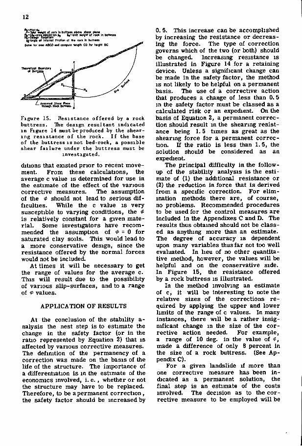
Figure 15. Resistance offered by a rock buttress. Hie design resultant indicated in Figure 14 must be produced by the shearing resistance of the rock. I f the base of the buttress IS not bed-rock, a possible shear f a i l u r e under the buttress must be
investigated.
ditions that existed prior to recent movement. From these calculations, the average c value is determined for use in the estimate of the effect of the various corrective measures. The assumption of the <t> should not lead to serious difficulties. While the c value is very susceptible to varying conditions, the <)> is relatively constant for a given material. Some investigators have recommended the assumption of 0 = 0 for saturated clay soils. This would lead to a more conservative design, since the resistance offered by the normal forces would not be included.
At times it will be necessary to get the range of values for the average c. This will result due to the possibility of various slip-surfaces, and to a range of <t> values.
APPLICATION OF RESULTS
At the conclusion of the stability a-nalysis the nest step is to estimate the change in the safety factor (or in the ratio represented by Equation 2) that is affected by various corrective measures. The definition of the permanency of a correction was made on the basis of the life of the structure. The importance of a differentiation is in the estimate of the economics involved, i . e., whether or not the structure may have to be replaced. Therefore, to be apermanent correction, the safety factor should be increased by
0. 5. This increase can be accomplished by increasing the resistance or decreasing the force. The type of correction governs which of the two (or both) should be changed. Increasing resistance is illustrated in Figure 14 for a retaining device. Unless a significant change can be made in the safety factor, the method IS not likely to be helpful on a permanent basis. The use of a corrective action that produces a change of less than 0. 5 in the safety factor must be classed as a calculated risk or an expedient. On the basis of Equation 2, a permanent correction should result in the shearing resistance being 1. 5 times as great as the shearing force for a permanent correction. If the ratio is less than 1.5, the solution should be considered as an expedient
The principal difficulty in the follow-up of the stability analysis is the estimate of (1) the additional resistance or (2) the reduction in force that is derived from a specific correction. For elimination methods there are, of course, no problems. Recommended procedures to be used for the control measures are included in the Appendixes C and D. The results thus obtained should not be classed as anything more than an estimate. The degree of accuracy is dependent upon many variables thus far not too well evaluated. In lieu of no other quantitative method, however, the values will be helpful and on the conservative side. In Figure 15, the resistance offered by a rock buttress is illustrated.
In the method involving an estimate of c, it will be interesting to note the relative sizes of the corrections required by applying the upper and lower limits of the range of c values. In many instances, there will be a rather insignificant change in the size of the corrective action needed. For example, a range of 10 deg. in the value of 0 , made a difference of only 8 percent in the size of a rock buttress. (See Appendix C).
For a given landslide if more than one corrective measure has been indicated as a permanent solution, the final step is an estimate of the costs involved. The decision as to the corrective measure to be employed will be

13
made on the basis of economy, appearance, effect of the change on driver-safety, or by such other means as established as the policy of the organization concerned.
SUMMARY AND CONCLUSIONS
(1) For highway engineers, the basis for the classification of landslides should be on the mechanics of the movement rather than on cause and effect.
(2) For a given highway-landslide problem there are numerous solutions that can be satisfactorily applied, and the problem can be reduced to a problem in economics.
(3) While the detrimental effect of water has been repeatedly emphasized, the fact that has not been sufficiently emphasized is that the force of gravity is always present as a contributing factor.
(4) By classifying the types of corrective measures in common use, it is possible to clarify the method of analysis of a given landslide.
(5) A preliminary analysis of a landslide should lead to an estimate of the types of corrections to be used. This should reduce the cost of investigating some problems.
(6) The field work should produce all possible data on the location of the slip-surface. The critical factor in the office analysis is the accuracy of the delineation of the slip-surface.
(7) At the moment ]ust before failure the force tending to cause movement is equal to the resistance to movement. The problem is to determine these forces.
(8) The analyses of a landslide should be governed by the basic principle of obtaining a more stable slope than existed prior to failure. At the present time, the best method for estimating quantitatively the relative stability is the formula:
ST = 2 N tan 0 + c L (2)
(9) The forces acting against a re-taimng device can be estimated as can the resistance offered by the retaining device.
(10) The beneficial effect of any c o r
rective action can be estimated in terms of Equation 2.
(11) The procedure suggested may be an over-simplification in its present form. Observations and evaluation of the corrective measures thus far effected will be necessary.
(12) Considerable research work is necessary to better determine the actual shearing forces and shearing resistances at work in a landslide.
(13) Extensive research is needed to determine an inexpensive method for solving highway landslide problems.
R E F E R E N C E S
1. Tompkin, J . M. and Britt, S. B . , "Landslides - A Selected Annotated Bibliography", Bibliography No. 10, Highway Research Board, 1951.
2. Sharpe, C. F . S . , "Landslides and Related Phenomena", Columbia University Press , 1938.
3. Ladd, Dr. George E . , "Landslide, Subsidences and Rock-Falls", Bulletin, American Railway Engineering Association, Volume 37, No. 377, July, 1935.
4. Terzaghi, Dr. K a r l , "Mechanism of Landslides", Berkey Volume, The Geological Society of America, 1950.
5. Terzaghi, Dr. K a r l and Peck, Ralph B . , "Soil Mechanics in Engineering Practice", John Wiley and Sons, 1948.
6. Krynine, D. P . , "Soil Mechanics", McGraw-Hill Book Company, 1941.
7. Hennes, R. G . , Bulletin, University of Washington Engineering Experiment Station, No. 91, June 1936.
8. Taylor, Donald W. , "Fundamentals of Soil Mechanics", John Wiley and Sons, 1948.
9. Lambe, T. W. , Discussion of "Landslide Investigation and Correction" by Hyde Forbes, Transaction, A -merican Society of Civi l Engineers, 1947.
10. Krynine, D. P . , "Landslides and Pile Action", Engineering News-Record, Volume 107, No, 122, November 26, 1931.
11. Larew, H. G . , "Use of Field, Laboratory, and Theoretical Procedures
14
for Analyzing Landslides", Thesis, Purdue University, November, 1951.
12. Price, Paul H. and Lil ly , K. O . , "An Investigation of Landslides Affecting Roads in West Virginia", unpublished report to State Road Commission of West Virginia, 1940.
13. Baker, R. F . , "An Analysis of Corrective Actions for Highway Landslides", report prepared for Louisville Convention, American Society of Civil Engineers, June 13-15,
1951 (In hands of publication committee of the American Society of Civil Engineers).
14. Forbes, Hyde, "Landslide Investigation and Correction", Transaction, American Society of Civil Engineers, 1947.
15. Larew, H. G . , "Use of Field, Laboratory and Theoretical Procedures for Analyzing Landslides", Proceedings, Highway Research Board, Vol. 31, 1952.
A P P E N D I X A
T Y P I C A L S T A B I L I T Y ANALYSIS
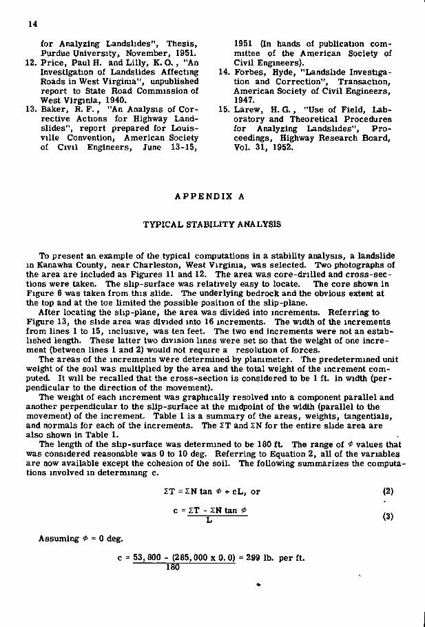
To present an example of the typical computations in a stability analysis, a landslide in Kanawha County, near Charleston, West Virginia, was selected. Two photographs of the area are included as Figures 11 and 12. The area was core-drilled and cross-sections were taken. The slip-surface was relatively easy to locate. The core shown in Figure 6 was taken from this slide. The underlying bedrock and the obvious extent at the top and at the toe limited the possible position of the slip-plane.
After locating the slip-plane, the area was divided into increments. Referring to Figure 13, the slide area was divided into 16 increments. The width of the increments from lines 1 to 15, inclusive, was ten feet. The two end increments were not an established length. These latter two division lines were set so that the weight of one increment (between lines 1 and 2) would not require a resolution of forces.
The areas of the increments were determined by planimeter. The predetermined unit weight of the soil was multiplied by the area and the total weight of the increment computed. It will be recalled that the cross-section is considered to be 1 ft. in width (perpendicular to the direction of the movement).
The weight of each increment was graphically resolved into a component parallel and another perpendicular to the slip-surface at the midpoint of the width (parallel to the movement) of the increment. Table 1 is a summary of the areas, weights, tangentials, and normals for each of the increments. The IT and SN for the entire slide area are also shown in Table 1.
The length of the slip-surface was determined to be 180 f t The range of * values that was considered reasonable was 0 to 10 deg. Referring to Equation 2, all of the variables are now available except the cohesion of the soil. The following summarizes the computations involved in determimng c.
ST = SN tan < + c L , or
c = ZT - ZN tan 0
(2)
(3)
Assuming 0 = 0 deg.
c = 53, 800 - (285,000 x 0. 0) = 299 lb. per ft. 180

15
TABLE 1
VALUES or TANGDniAL AND NOniAL FORCES IN A TYPICAL STABIUTJ ANALYSIS
15! 0-1 1.2 1 - j }-» t.s s-6 i-i 7^ a.) ^10 10.11 11-12 12-13 lyu ls-l(
I ncmtn t Ar t i
(Sq. F t . ) l U 120 I2B 1(0 I7( 1)2 IJ2 lOS iCl 17) 2IJ 200 In !(• !« I2<
IncrMint -Jtioht
( U n K U i i g K t : 110 lb« . I I .UO 13,200 K.OtO 17,(00 I3,3S0 21,100 21,100 20,(50 lO.SOO 13,700 23,eoO 22,000 21,200 IS.JOO IS,es0 IJ.CjO
p.r cu. f t . )
Tanotntial Fore*
(Lb. . ) -2,100 0 1,000 2,S00 3,200 3,300 4,000 3,800 <,000 4,300 3,000 4,000 5,000 4,J0O 4,300 3,000
Nona I Ferca
(Iba.) 11,100 13,200 14,100 17,100 13,200 21,000 20,800 20,200 18,100 13,200 23,200 21,800 21,000 18,000 13,300 12,300
lntar | ]ranulBr Forca ( U . . ) 5,580 ( , I IO (,240 7,4«0 >, l (0 8,850 a,8;0 S^JO 8,230 8,500 3,(00 J,350 S,7«0 8,730 7,480 7,240
S T = 53.600 Z N = les.eoo S (N - W = 155. S »
Assuming < = 10 deg.
c = 53,800 - (285,800 x 0.1763) = 18 lb. per f t 186
The relatively low c value for this silty-clay soil indicates that * is probably smaller than 10 deg., or that there were strong hydrostatic or seepage forces existing at the time of movement.
For the particular slide in question, assume that the ground water lies as shown in Figure 13. The equation which can be used to account for the hydrostatic pressure is as follows:
XT = 5:(N - M) tan < + c L , or (4)
c = I T - S(N - A ) tan L
Where M = h y ^1 = water pressure in lb. at the slip-plane h = depth in feet from ground water line to slip-plane
= unit weight of water = 62. 4 lb. per cu. ft. 1 = length of increment in feet along slip-plane
The values for (N - M) are listed in Table 1 as intergranular forces. For < = 0 deg., there is no change in c due to hydrostatic pressures since
tan <P = 0.0
For 0 = 10 deg., the following is indicated:
c = 53. 800 - (155. 530 x 0.1763) 180
c = 147 lb. per f t
16
A P P E N D I X B
ELIMINATION METHODS
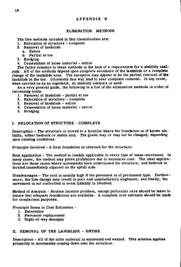
The five methods included in this classification are: 1. Relocation of structure - complete 2. Removal of landslide
a. Entire b. Partial at toe
3. Bridging 4. Cementation of loose material - entire The factor common to these methods is the lack of a requirement for a stability anal-
ysiiB. Al l of the methods depend upon complete avoidance of the landslide or a complete change of the landslide area. The exception may appear to be the partial removal of the landslide at the toe. Ultimately this will lead to near complete removal. In any event, when carried on as an e}q)edient, no stability analysis is used.
As a very general guide, the following is a list of the elimination methods in order of increasing costs.
1. Removal of landslide - partial at toe 2. Relocation of structure - complete 3. Removal of landslide - entire 4. Cementation of loose material - entire 5. Bridging
I. RELOCATION OF STRUCTURE - C O M P L E T E
Description - The structure is moved to a location where the foundation is of known stability, either bedrock or stable soil. The grade may or may not be changed, depending upon existing conditions.
Principle Involved - A firm foundation is obtained for the structure.
Best Application - The method is readily applicable to every type of mass-movement. In many cases, the method may prove prohibitive due to excessive cost. The ideal applications are those cases where movements have undermined the structure, and bedrock is located immediately adjacent on the uphill side.
Disadvantages - The cost is usually high if the pavement is of permanent type. Furthermore, the line change may result in poor and unsatisfactory alignment, and finally, the movement is not controlled in event liability is involved.
Method of Analysis - Routine location problem, except particular care should be taken to insure that adequate foundations are available. A complete cost estimate should be made for comparison purposes.
Principle Items in Cost Estimates -1. Excavation 2. Pavement replacement 3. Right-of-way damages
II . REMOVAL OF THE LANDSLIDE - E N T I R E
Description - All of the slide material is excavated and wasted. This solution applies primarily to movements coming down onto the structure.

17
Prlnelple Involved - The moving mass that is causing the problem is completely removed.
Best Aiqplication - Ideally suited to shallow soil profiles (10 to 20 ft. )and small moving areas (100 to 150 ft. from structure to top of slide). The area above the slide should be stable or worthless, or the question of additional failures should be considered.
Disadvantages - May be too costly for extensive movements. Design care must be taken to insure against undermining the area above, particularly with regard to rockfalls.
Method of Analysis - Normally, the only analyses necessary are for the computations of quantities involved. In cases of questionable stability above the slide area, a stability analysis of the slope above may be required.
PrlQciple Items in Cost Estimate -1. Excavation 8. Right-of-way damages
m. REMOVAL O F LANDSLIDE - PARTIAL A T T O E
Description - The debris is moved from the area affecting the structure in order to relieve pressure, remove obstacle, etc. Since part of the toe is removed continued movement is inevitable. The method should rarely be used except as an emergency measure. An immediate follow-up with a permanent solution is necessary to prevent future movement.
Principle Involved - The moving mass is excavated so as to permit passage of vehicles, to temporarily relieve pressure against a structure, etc.
Best Application - Very rarely applicable except when movement is down onto structure from above. The method will most often be necessary in instances where the mass has moved against a structure or has blocked a roadway. In instances involving valueless land above, removal of the toe with space provided for future movement may be an economical solution.
Disadvantages - This e:q>edient method does not produce a permanent solution.
Method of Analysis - No analysis is necessary except for quantities involved in a cost estimate. For determining follow-up or permanent correction, a stability analysis of tbe type required for the permanent solution will be necessary.
Principle Items in Cost Estimate -1. Excavation 2. Right-of-way damages
IV. CEMENTATION OF LOOSE MATERIAL - ENTIRE
Description - In order to obtain stable material, cement grout is injected into the moving area. This produces a material that has higher shear resistance. In cohesive soils vertical columns are obtained and their effect is that of a system of piling. The same principle is applied when only a portion of the moving mass near the toe is stabilized to produce a buttress.
Principle Involved - The shearing resistance is increased by improving the shear characteristics of the moving mass. In cohesive soils the resisting forces are increased by a transference of load from the moving mass to the underlying stable material.
18
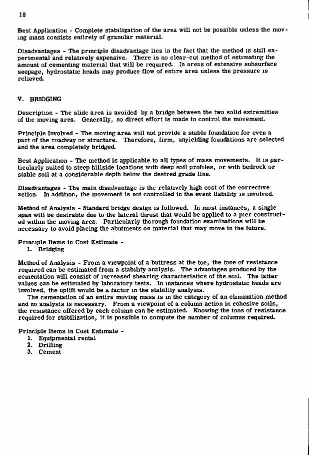
Best Application - Complete stabilization of the area will not be possible unless the moving mass consists entirely of granular material.
Disadvantages - The principle disadvantage lies in the fact that the method is still experimental and relatively expensive. There is no clear-cut method of estimating the amount of cementing material that will be required. In areas of extensive subsurface seepage, hydrostatic heads may produce flow of entire area unless the pressure is relieved.
V. BRIDGING
Description - The slide area is avoided by a bridge between the two solid extremities of the moving area. Generally, no direct effort is made to control the movement.
Principle Involved - The moving area will not provide a stable foundation for even a part of the roadway or structure. Therefore, f irm, unyielding foundations are selected and the area completely bridged.
Best Application - The method is applicable to all types of mass movements. It is particularly suited to steep hillside locations with deep soil profiles, or with bedrock or stable soil at a considerable depth below the desired grade line.
Disadvantages - The main disadvantage is the relatively high cost of the corrective action. In addition, the movement is not controlled in the event liability is involved.
Method of Analysis - Standard bridge design is followed. In most instances, a single span will be desirable due to the lateral thrust that would be applied to a pier constructed within the moving area. Particularly thorough foundation examinations will be necessary to avoid placing the abutments on material that may move in the future.
Principle Items in Cost Estimate -1. Bridging
Method of Analysis - From a viewpoint of a buttress at the toe, the tone of resistance required can be estimated from a stability analysis. The advantages produced by the cementation will consist of increased shearing characteristics of the soil. The latter values can be estimated by laboratory tests. In instances where hydrostatic heads are involved, the uplift would be a factor in the stability analysis.
The cementation of an entire moving mass is in the category of an elimination method and no analysis is necessary. From a viewpoint of a column action in cohesive soils, the resistance offered by each column can be estimated. Knowing the tons of resistance required for stabilization, it is possible to compute the number of columns required.
Principle Items in Cost Estimate -1. Equipmental rental 2. Drilling 3. Cement

19
A P P E N D I X C
DESCRIPTION OF CONTROL METHODS - RETAINING DEVICES
The corrective measures included in this classification are: 1. Buttresses
a. Rock b. Cementation of loose material at the toe c. Chemical treatment - flocculation - at toe d. Excavate, drain, and backfill - at toe e. Relocation - raise grade at toe f. Drainage of the toe
2. Cribbing - concrete, steel, or timber 3. Retaining wall - masonry or concrete 4. Piling - steel, concrete or timber
a. Floating b. Fixed - no provisions for preventing extrusion c. Fixed - provision for preventing extrusion
5. Tie-rodding slopes
Further details are available on the following: Cementation of loose material - Appendix B Chemical treatment - flocculation - Appendix D Excavate, drain, and backfill - Appendix D Relocation - Appendix B Drainage - Appendix D
Description - A resistance is placed in the path of the moving mass. The resistance IS placed somewhere between the structure, or area to be protected, and the toe of the slide.
Principles Involved - Since all retaining devices produce additional resistance to movement, the benefit derived is resisting force that will be added to the shearing resistance (Equation 2).
Advantages - Retaining devices will often permit correction with the least amount of right-of-way damages. In certain cases, only a part of the landslide is brought under control, and a savings is realized over an attempt to control the entire movement. When the area is exposed to stream erosion, the retainer can be designed as a slope protection device.
Disadvantages - Except for floating piles, most retaimng devices represent a relatively expensive solution. In addition, except for cribbing, failure of the method will result in a complete loss of the investment involved in the corrective action.
Method of Analysis - Having completed a stability analysis, the point at which the retainer is to be used is selected. The assumed value of <f> and the average c as computed in the stability analysis are used to obtain the summation of the shearing forces and shearing resistances for the area between the location of the retainer and the top of the slide. This is shown diagrammatically in Figure 14. The summation of shearing forces (IT) is multiplied by 1. 5. This product will represent the summation of the required shearing resistance for a permanent solution. The actual shearing resistance of the soil is subtracted from the required shearing resistance, and the difference is the force that the retainer must be able to resist without failure.
20
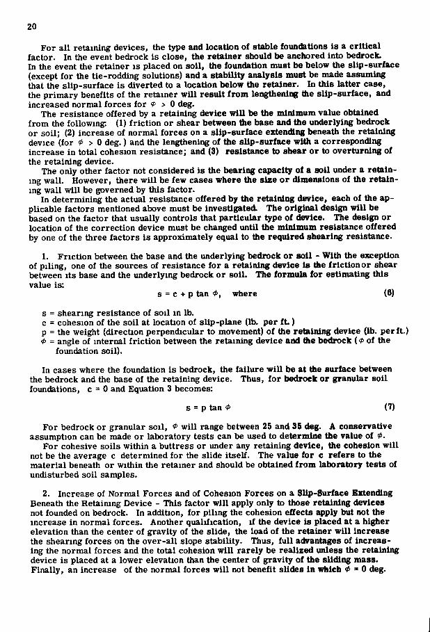
For all retaining devices, the type and location of stable foundations is a critical factor. In the event bedrock is close, the retainer should be anchored into bedrock. In the event the retainer is placed on soil, the foundation must be below the slip-surface (except for the tie-rodding solutions) and a stability analysis must be made assuming that the slip-surface is diverted to a location below the retainer. In this latter case, the primary benefits of the retainer will result from lengthening the slip-surface, and increased normal forces for > 0 deg.
The resistance offered by a retaining device will be the minimum value obtained from the following: (1) friction or shear between the base and the underlying bedrock or soil; (2) increase of normal forces on a slip-surface extending beneath the retaining device (for * > 0 deg.) and the lengthening of the slip-surface with a corresponding increase in total cohesion resistance; and (3) resistance to shear or to overturning of the retaining device.
The only other factor not considered is the bearing capacity of a soil under a retaining wall. However, there will be few cases where the size or dimensions of the retaining wall will be governed by this factor.
In determining the actual resistance offered by the retaining device, each of the applicable factors mentioned above must be investigated The original design will be based on the factor that usually controls that particular type of device. The design or location of the correction device must be changed until the minimum resistance offered by one of the three factors is approximately equal to the required shearing resistance.
1. Friction between the base and the underlying bedrock or soil - With the exception of piling, one of the sources of resistance for a retaining device is the friction or shear between its base and the underlying bedrock or soil. The formula for estimating this value is:
s = c + p tan where (6)
s = shearing resistance of soil in lb. c = cohesion of the soil at location of slip-plane (lb. per ft.) p = the weight (direction perpendicular to movement) of the retaining device (lb. per ft.) <P = angle of internal friction between the retaining device and ttie bedrock ( 0 of the
foundation soil). In cases where the foundation is bedrock, the failure will be at the surface between
the bedrock and the base of the retaining device. Thus, for bedrock or granular soil foundations, c = 0 and Equation 3 becomes:
s = p tan 0 (7)
For bedrock or granular soil, 0 will range between 25 and 35 deg. A conservative assumption can be made or laboratory tests can be used to determine the value of 0 .
For cohesive soils within a buttress or under any retaining device, the cohesion will not be the average c determined for the slide itself. The value for c refers to the material beneath or within the retainer and should be obtained from laboratory tests of undisturbed soil samples.
2. Increase of Normal Forces and of Cohesion Forces on a Slip-Surface Extending Beneath the Retaining Device - This factor will apply only to those retaining devices not founded on bedrock. In addition, for piling the cohesion effects apply but not the increase in normal forces. Another qualification, if the device is placed at a higher elevation than the center of gravity of the slide, the load of the retainer will increase the shearing forces on the over-all slope stability. Thus, full advantages of increasing the normal forces and the total cohesion will rarely be realized unless the retaining device is placed at a lower elevation than the center of gravity of the sliding mass. Finally, an increase of the normal forces will not benefit slictes in which 0 = 0 deg.

21
The computation of this factor is accomplished by dividing the cross-section into Increments similar to those used In the original stability analysis. For the new slip-surface (recalling that the foundations of the device must be placed below the original slip-surface) the summation of the normal forces will be increased and the length will be greater with a corresponding Increase of cohesion resistance.
3. Resistance to shear or to overturning of the retaimng device - In order to estimate the resistance to shear or to overturning of the retaining device, it is necessary to know the magnitude, distribution, point and direction of application of the forces acting on the retainer. A suggested method for determining these factors is pictured In Figure 15. From the stability analysis, the required shearing resistance can be determined. The horizontal component of the force can be evaluated by graphical resolution. It is then a reasonable assumption that the force decreases uniformly to a value of zero at the ground surface. There is a vertical component of the required tangential force but the vertical force can be neglected unless the retaining device is placed over a steep portion of the slip-plane. This force does change the direction of the resultant. However, it can be assumed that the resultant acts parallel to the slip-surface. See Figure 15.
D E T A I L S ON INDIVIDUAL METHODS
1. Buttresses - all types - In each instance, the slip-plane should be assumed to be extending through the buttress. For rock and cementation of loose material at the toe, the slip-surface through the buttress can be assumed to be a straight line extension (Fig. 15). The resistance can be computed from Equation 7. The resistance required at this point is the required tangential force obtained in the stability analysis. Theoretically, a rock buttress should be a triangle that is sufficiently large so as to resist the shear at any point. As a practical consideration, however, the top of the buttress is normally built horizontal for 5 to 10 ft. In Figure 15, a line shows the theoretical limits within which the edge of the buttress should fall. The horizontal widths at various levels are defined by the uniform reduction from the maximum at the slip-plane to zero at the ground surface.
For the buttresses Involving soil materials, the resistance of the buttress to shear is computed by Equation 6. The 4 and c of the material m the buttress should be determined by laboratory tests. For the drainage solution, laboratory permeability tests or field well points should be used to determine the feasibility of drainage. Furthermore, the 0 and c values should be those obtained from laboratory tests on a sample of the soil imder the reduced moisture conditions.
Referring to the example used in Appendix A and to Figures 14 and 15, the following is a typical example of the computations for a rock buttress:
For « = 0 deg., c = 299 lb. per ft . , L = 144 ft. for buttress at line 3. ZT = 54,900 lb. (from line 3 to 16, inclusive) ZN = 247,400 lb. (from line 3 to 16, inclusive) 1.6 X ZT = 82,350 lb. c L = 144x299 = 43,000 lb. I N ton * + c L = 0 + 43,000 = 43,000 lb.
R p = 82,350 - 43,000 = 39,350 lb. R 0 = (rp X Area ABCD) tan «b
«• 100 lb. per cu. ft. « B = 50 <teg. Area ABCD = ^ " ' " ^ = 680 sq. ft.
57. 54
For * = 10 deg., c = 18 lb. per ft. 1.5 T = 82,350 lb. Z M tan * + c L = (247,400 x 0.1763) + (18 x 144) = 46,140 lb.
Rrj = 82,350 - 46,140 = 36,210 lb. Area ABCD = 36,210 = 632 sq. ft.
57. 75

22
From the foregoing, the condition of <f = 0 deg. gives an 8 percent more conservative figure than that of < - 10 deg., therefore, design the buttress with at least 680 sq. ft. Assuming that the exposed slope of the buttress is on a 1 1/2 : 1 slope (Horizontal: Vertical), and the backslope is vertical:
Bases of buttress = Area + 1. 5h ~ir '-2-
If h = 16 ft.
Top width = 680 - 12 = 30. 5 f t "16
Base width = 680 + 12 = 54. 5
The principle items of cost in a buttress are as follows. Not all of the items will be required in every buttress.
(a) Excavation (b) Backfill (Rock or Soil) (c) Admixture (Cement or Chemical) (d) Drainage Pipe (e) Drilling (for Admixtures) (f) Equipment Rental (for Admixtures)
2. Cribbing and Retaining Walls - Use is made of standard design methods for the type of wall under consideration. Cribbing should be considered as a gravity-type wall. The magnitude, point of application, and direction of the stresses against the wall will be as indicated in Figure 14.
3. Piling - In order to be fully effective, the piling should extend one-third of its length below the slip-surface. The following is a formula for resistance to shear of the piles (7):
Ap X ly , (gj ^ ' D
s = shearing resistance offered by a pile, in lb. per inch (in a direction perpendicular to the movement)
Ap = cross-section area of the pile in square inches fy = allowable stress in shear for the pile, pounds per square inch D = center-to-center spacing of the piles in inches
A pile should also be checked for the resistance to the soil shearing along each side of the pile. A formula has been suggested by Hennes (7):
s = 2 chd (9)
s = shearing resistance per pile in lb. c = cohesion of the soil, lb. per sq. ft. h = height from slip-surface to ground surface in feet d = diameter of the pile in feet
A sufficient number of piles must be available so that the soil shearing resistance or the sum of the shearing resistance of the piles are equal to or greater than the required resultant of the horizontal forces (Fig. 15). The piling will not be subjected to cantilever action until movement has occurred. Due to partial restraint offered by the surrounding material, it should not be necessary to compute the stability of the piles from a cantilever viewpoint unless there is a possibility of movement of the area below the piling.

23
Referring to the example used in Appendix A, no experienced engineer or geologist would be likely to recommend piling at the location selected for the buttress (Line 3) The computations verify this opimon:
Assuming a 12 in. diameter, timber pile with a cross-section area of 113.1 so in and 0 = 0 deg., c = 299 lb. per ft.
= Vliv (8) fy = 100 lb. per sq. in. s = 39^50 lb. per in.
D = 113.1 X 100 X 12 = 3.45 in. 35759i5
s = 2 c h d . (9) = 2 X 299 X 15 X 1 = 8970 lb. per pile
39,350 = 4. 4 piles per ft.
D = 12 = 2. 7 in. X T
For * = 10 deg., c = 18 lb. per sq. ft.
s = 2 X 18 X 15 X 1 = 540 lb. per pile
39,350 = 73 piles per f t
D = 12 = 0.16 in. 73
The obviously low value of 18 pounds per ft. for the cohesion is not a legitimate figure to use unless the material is very fluid. It will be recalled that the average c of 18 lb. per ft. represents the material at the slip-plane. It is not unreasonable to expect a much weaker material at the slip-plane. A more legitimate value for c in Equation 9 is a representative c for the material from the slip-surface to the ground surface at the location of the piles. This could be adequately determined from laboratory tests.
A more reasonable location of piling would beatLine 10 (Fig. 13). The computations follow:
For 0 = 0 deg., c = 299, 12 in. diameter timber pihng
2T = 29,600 lb. (lines 10 to 16, inclusive) L = 66 ft. 1. 5 T = 44,400 c L = 19, 734
Rj) = 24,666 D = 135,800 = 5. S i n .
For average c = 400 lb. per sq. ft. (above slip-plane)
s = 2 X 400 X 16 X 1 = 12,800 lb. per pile
24
24,600 = 1. 7 piles per ft. T57800
D = 12 = 6. 7 in. TT?
The use of steel or concrete piles would permit wider spacing. The computations would be similar to those for timber piling. However, even a location near the roadway would require very close pile-spacing for a permanent solution.
4. Tie-Rodding Slopes - Resistance will be offered by the piling, cribbing or other retaining device. The remainder of the required resultant must come from the anchorage system. The required resultant (Fig. 15) must be equalled or exceeded by the combined resistance of the retainer and anchorage. The resisting force obtained from the tensile strength of a number ol steel bars of a given dimension.
Relative Cost - As a very general guide, the following is a list of the retaimng devices in order of increasing costs:
1. Piles - floating 2. Buttress - rock 3. Buttress - excavate, drain and backfill at toe 4. Buttress - relocation - raising grade at toe 5. (a) Buttress - cementation of loose material at toe
(b) Chemical treatment - flocculation - at toe 6. (a) Cribbing
(b) Piling - fixed - no provision for preventing extrusion 7. (a) Tie-rodding slopes
(b) Piling - fixed - provision for preventing extrusion 8. Retaining wall
A P P E N D I X D
CONTROL METHODS - DIRECT REBALANCE OF RATIO B E T W E E N RESISTANCE AND F O R C E
The corrective measures included in this classification are: 1. Drainage
a. Surface (1) Reshaping landslide surface (2) Slope treatment
b. Sub-surface (French drain type) c. Jacked-in-place or drilled-in-place pipe d. Tunnelling e. Blasting f. Sealing joint planes and open fissures
2. Removal of material - partially at tope 3. Light-weight f i l l 4. Relocation - lower grade at top 5. Excavate, drain, and backfill - entire 6. Chemical treatment - flocculation - entire
Further details are available on the following: Relocation - Appendix B Removal of Material - Appendix C

25
Chemical Treatment - Flocculation - Appendix C Excavate, Drain and Backfill - Appendix C Drainage - Appendix C
Description - The forces that are contributing to the movement are decreased or the natural sources of the resistance to movement are increased. There is no artificial treatment with the exception of chemical treatment
Principles Involved - The drainage solutions may depend upon the reduction of the shearing forces by the elimination of part of the weight of the moving mass. Drainage may also increase the shearing resistance by increasing c or increasing the intergranular forces (normals) by eliminating hydrostatic pressures. Methods other than drainage either reduce the shearing stresses to a greater extent than the reduction of the normal forces or increase the c value of the soil by increased densities or by treatment of the soil. Chemical treatment may also reduce the water-holding capacity of the soil, which would tend to reduce the shearing forces. Blasting combines the advantages of drainage and the permanent displacement (vertically, upward) of the slip-surface. The slip-plane dispacement by blasting tends to reduce the shearing forces by decreasing the weight of the moving mass, while the beneficial effects of drainage are probably temporary.
Disadvantages - Most of the drainage methods are rather costly, as are excavating, draining and backfilling and chemical treatment Also, the estimate of the value to be obtained from a drainage solution is extremely difficult. For sealing joint planes, there IS a problem of determining whether or not the seepage will develop in another location.
There may be construction problems in installing drainage below the slip-surface in the moving mass. Furthermore, the advantages from drainage of cohesive soil masses may be delayed or may never develop due to low permeability.
Method of Analysis - Having completed the basic stability analysis and having the average c value to be used, the reduction in shearing forces is estimated for the drainage solution by estimating probable reduction of unit weight of the moving mass, and for removal of material at top, relocation by lowering grade at top, and the light-weight fil l . The increase of shearing resistance Results from the increase of c value for the following: all drainage solutions (except blasting); excavating, draining, and backfilling; and for chemical treatment. There is an increase of normal force due to eliminating hydrostatic pressures for all drainage solutions, and for excavation, drain and backfill.
The method of analyzing for hydrostatic pressures is a complex field problem of measuring existing ground-water levels (or excess hydrostatic pressures) and estimating probable maximum height. In computations, the effect is shown by Equation 5 or Appendix A. If hydrostatic pressures are to be considered. Equation 5 should be used instead of Equation 1 or 2, in the original stability analysis.
The excess hydrostatic pressures will be particularly troublesome in landslides that contain pockets or layers of free-draining material. It is probable that such pressures are also troublesome in areas where water is relatively free to move down the slip-plane.
Terzaghi (4) points out that in impermeable soils, flash pressures may develop due to heavy rains. Such pressures are relieved before a significant change can be brought about in the water table. He, therefore, recommends a form of piezometric tube to observe these phenomena in the field.
It should be emphasized that the effort to check the effect of hydrostatic pressures is necessary in the procedure outlined herein in order to determine the degree of improvement brought about by drainage solutions. The values obtained by Equations 1 and 2 will be misleading from an academic consideration. However, it is assumed that the most serious condition has been accounted for in the computation of the average c. The

26
TAELE 2
DETAILS FOR UafT-mCHT HLL
Increment
9-10 10-U 11- 12 12-13 13-14 14-15 15-16
Weight of original soil ( lb ) 19,700 23,800 22,000 21,200 18,500 15,850 13,650
Increment area (sq f t . ) 25 75 105 105 105 105 116
Increment weight (unit weight = 110 lb per cu. f t ) 2,750 8,250 11,550 11,550 11,550 11,550 12,700
Weight of soil ( lb ) 16,950 15,550 10,450 9,650 6,950 4,300 950
Weight of L W f i l l (unit weight = 40 lb per cu f t ) 1,000 3,000 4, 200 4,200 4.200 9,200 5,920
Total weight of soil + L.W f i l l ( l b . ) 17,950 18,550 14,650 13,850 11,150 8,500 6,870
Normal force ( lb ) 17.500 18,200 14,500 13,750 10,850 8,200 6,300
Tangential force ( lb ) 3,920 3,900 3,200 3,260 2,720 2,410 2,920
For area between lines 9 and 16, inclusive, with light-weight f i l l Z N = 89,300 lb . 2 T = 22,330 lb
For entire area with light-weight f i l l lN = 89,300 + 154,800 = 244,100 lb I N = 22,330 + 19.900 = 42,230 lb.
relief of hydrostatic pressure by the installation of a drainage system is not reflected in the stability computations using Equations 1 and 2.
Referring to the example used in Appendix A, for the case of <P = 10 deg., the average c was computed to be 147 lb. per ft . , using Equation 5. If a drain were installed at Line 16, below the slip-plane, and in a position to lower the groundwater table so that it coincided with the position of the slip-plane, the following computations indicate the improvement in stability:
S. F . = 2(N -/x)tan 0 + c L T (5)
(285,800 - 0) x 0.1763 + (180 x 147) 537800
= 1.43
Thus, the installation of the drain would increase the safety factor by 0. 43, which would be sufficient to be termed a permanent solution.
TABLE 3
DETAILS FOR RELACATION - LOWERING ROAD CBADE AT TOP OF SLIDE
Increment
9-10 10-11 11-12 12-13 13-14 14-15 15-16 I
Weight of soil ( lb ) 16,950 15, 550 10,450 9,650 6,950 4, 300 950
Tangential force ( lb ) 3,700 3,270 2,280 2,280 1,690 1,220 405 14,84!
Normal force ( lb ) 16,500 15,100 10,400 9,550 6,750 4,180 870 63, 55(
For area between lines 9 and 16, inc lusive I N = 63,550 lb I T = 14,845 lb .
27
Referring to the same example the value to be obtained from a li^t-weight f i l l can be estimated as follows.
Assume that the area between Lines 9 and 16, inclusive, and above the elevation 90.0 is to be removed and replaced with a light-weight material that weighs 40.0 lb. per cu. ft. (unit weight of original soil =110 lb, per cu. ft.) . Table 2 summarizes the change in normal and tangential forces between Lines 9 and 16, inclusive.
Assuming = 0 deg., c = 299 lb. per ft.
S. F . = ZN tan + c L ZT
= (244,100 X 0) + (299 x 180) 327^00
= 1.27 Assuming < = 10 deg,, c = 18 lb. per ft.
S . F , = (244,100 X 0.1763) + (18 x 180) ?Z73oo
= 1.1 Thus, the light-weight f i l l increases the safety factor by 0.1 to 0.27. This would
not be sufficient to be considered a permanent correction, K the grade of the road were lowered to an elevation of 90, 0, the following S. F . is
obtained (data in Table 3): Assuming * = 0 deg., c = 299
S. F . = ZN tan + c L (1) ST
= 0 + (299 X 180) = 1.55 —urm—
Assuming = 10 deg,, c = 18
S. F . = (218,150 X 0.1763) + (18 x 180)
= 1.20 Therefore, lowering the grade would fall slightly short of being a permanent solution.
The degree of importance to attach to the = 10 deg, assumption would be the controlling factor.
Relative Cost - As a very general guide, the following is the list of the methods that modify the shearing resistance or shearing force. This list is in order of increasing cost
1. Surface drainage - reshaping landslide surface 2. Surface drainage - slope treatment 3. Blasting 4. Light-weight f i l l 5. Removal of material - partially at top 6. Relocation - lowering grade at top 7. Jacked-in-place or dilled-in-place pipe 8. Subsurface (French drain type) 9. Tunnelling
10. Sealing joint planes or open fissures 11. Excavate - drain - backfill - entire 12. Chemical treatment - flocculation - entire