Determination of wind load, vertical and horizontal point ... parvekelasitus_eng... · Wind load...
10
TEST REPORT No. VTT-S-05602-10/EN 05.11.2010 Determination of wind load, vertical and horizontal point load and pendulum-impact resistance of NIKA-Universal Balcony Glass Curtain System Tilaaja: NIKA-Lasitus Ltd and Lasimies Ltd
Transcript of Determination of wind load, vertical and horizontal point ... parvekelasitus_eng... · Wind load...

TEST REPORT No. VTT-S-05602-10/EN 05.11.2010
Determination of wind load, vertical and horizontal point load and pendulum-impact resistance of NIKA-Universal Balcony Glass Curtain System
Tilaaja: NIKA-Lasitus Ltd and Lasimies Ltd

TEST REPORT No. VTT-S-05602-10/EN
1 (5)
The test results relate only to the sample tested. The use of the name of the Technical Research Centre of Finland (VTT) in advertising or publication in part of this
report is only permissible with written authorisation from the Technical Research Centre of Finland.
Requested by Lasimies Ltd Metallikatu 1 FI-15150 Lahti
Order Order on 5.5.2010 by Janne Nissinen, 15.6.2010 by Antti Kurvinen Confirmation of order VTT-O-102684-10, 18.6.2010
Contact person at VTT VTT Expert Services Ltd Eeva-Liisa Lepistö-Saukko Kemistintie 3, FI-02150 Espoo P.Box 1000, FI-02044 VTT
Tel. 020 722 5531 E-mail: [email protected]
Assignment Determination of wind load, vertical and horizontal point load and pendulum-impact resistance of NIKA-Universal Balcony Glass Curtain System
Samples Balcony Glass Curtain System was delivered to VTT Expert Services Ltd on 11.6.2010 and14.6.2010. Assembling of the Balcony Glass Curtain System to the test frame was carried out by NIKA-Lasitus Ltd.
Tested construction Tested construction of the NIKA-Universal Balcony Glass Curtain System
Manufacturer: NIKA-Lasitus Ltd
Product: NIKA-Universal Balcony Glass Curtain System
Dimensions: Height of the glazing system 1990 mm Height of the light opening 1762 mm Breadth of the glass pane: 710 mm
Type and dimensions of the glasses: 3 pcs of 8 mm thermally toughened safety glass panes, EN 12 600, manufactured by Lasimies Ltd
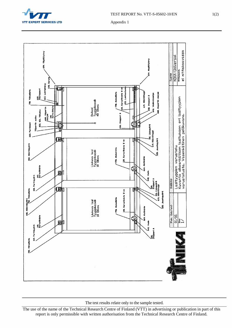
Component list and the structure of the terrace glazing system:
Appendix 1.
Upper and lower locks Figures 1 and 2. Upper and lower profiles: Wall thickness approx. 1,5 – 4,5 mm
Mounting of the glasses to the profiles: Upper and lower profile: 2 x 6 mm hole + Nylon-rivet + Bostik glass silicone all the way over the glass breadth Seals: Silicone
Safety: An unintentional drop of the glass out of the gate is prevented structurally
Turn and sliding of panes: Panes can be turned and slid aside the pane 1.

TEST REPORT No. VTT-S-05602-10/EN
2 (5)
The test results relate only to the sample tested. The use of the name of the Technical Research Centre of Finland (VTT) in advertising or publication in part of this
report is only permissible with written authorisation from the Technical Research Centre of Finland.
Figure 1. Lower lock/knob Figure2. Upper lock.
Performance of the task The terrace glazing system was assembled to the steel test frame by the manufacturer. The test frame was mounted to the decompression chamber as to a front wall. The inner side of the balcony glazing system was facing outwards from the chamber. Tests were performed on June 16, 2010 Test conditions: temperature 23°C and relative humidity 50 %. The following tests were carried out to the balcony glazing system in the presented order.
1. The wind load , EN 12211, Windows and doors – Resistance to wind load – Test method was applied.
The balcony glazing system was submitted to the positive and negative test pressures as follows:
three pressure impulses of 1320 Pa, positive pressure increasing positive and negative pressure up to the level of
1200 Pa and the measurements of the frontal deflection of the glass units
50 cycles of 600 Pa positive and negative pressure impulses safety test with one negative pressure impulse of 1800 Pa and
one positive pressure impulse of 1800 Pa glass units were opened and closed and the operation of the
systems was inspected
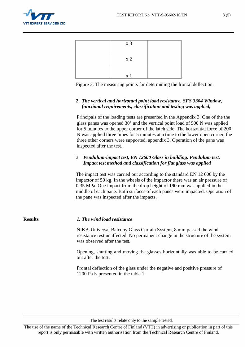
The frontal deflection of the glass units was measured at the 1200 Pa positive and negative pressure at the points presented in the figure 3. The sequence of the testing is shown in Appendix 2.
TEST REPORT No. VTT-S-05602-10/EN
3 (5)
The test results relate only to the sample tested. The use of the name of the Technical Research Centre of Finland (VTT) in advertising or publication in part of this
report is only permissible with written authorisation from the Technical Research Centre of Finland.
Figure 3. The measuring points for determining the frontal deflection.
2. The vertical and horizontal point load resistance, SFS 3304 Window, functional requirements, classification and testing was applied,
Principals of the loading tests are presented in the Appendix 3. One of the the glass panes was opened 30 and the vertical point load of 500 N was applied for 5 minutes to the upper corner of the latch side. The horizontal force of 200 N was applied three times for 5 minutes at a time to the lower open corner, the three other corners were supported, appendix 3. Operation of the pane was inspected after the test. 3. Pendulum-impact test, EN 12600 Glass in building. Pendulum test.
Impact test method and classification for flat glass was applied
The impact test was carried out according to the standard EN 12 600 by the impactor of 50 kg. In the wheels of the impactor there was an air pressure of 0.35 MPa. One impact from the drop height of 190 mm was applied in the middle of each pane. Both surfaces of each panes were impacted. Operation of the pane was inspected after the impacts.
Results 1. The wind load resistance
NIKA-Universal Balcony Glass Curtain System, 8 mm passed the wind resistance test unaffected. No permanent change in the structure of the system was observed after the test.
Opening, shutting and moving the glasses horizontally was able to be carried out after the test.
Frontal deflection of the glass under the negative and positive pressure of 1200 Pa is presented in the table 1.
x 3
x 2
x 1
TEST REPORT No. VTT-S-05602-10/EN
4 (5)
The test results relate only to the sample tested. The use of the name of the Technical Research Centre of Finland (VTT) in advertising or publication in part of this
report is only permissible with written authorisation from the Technical Research Centre of Finland.
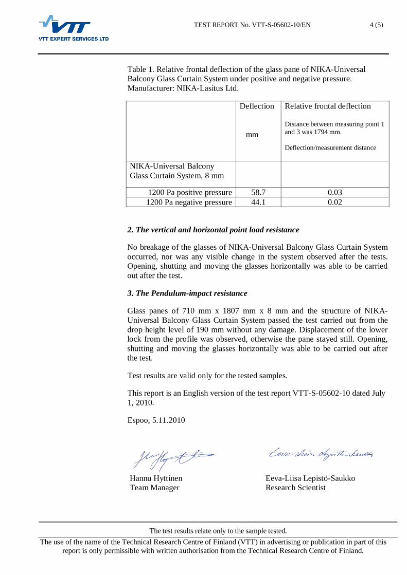
Table 1. Relative frontal deflection of the glass pane of NIKA-Universal Balcony Glass Curtain System under positive and negative pressure. Manufacturer: NIKA-Lasitus Ltd.
Deflection mm
Relative frontal deflection Distance between measuring point 1 and 3 was 1794 mm. Deflection/measurement distance
NIKA-Universal Balcony Glass Curtain System, 8 mm
1200 Pa positive pressure 58.7 0.03 1200 Pa negative pressure 44.1 0.02
2. The vertical and horizontal point load resistance
No breakage of the glasses of NIKA-Universal Balcony Glass Curtain System occurred, nor was any visible change in the system observed after the tests. Opening, shutting and moving the glasses horizontally was able to be carried out after the test.
3. The Pendulum-impact resistance
Glass panes of 710 mm x 1807 mm x 8 mm and the structure of NIKA-Universal Balcony Glass Curtain System passed the test carried out from the drop height level of 190 mm without any damage. Displacement of the lower lock from the profile was observed, otherwise the pane stayed still. Opening, shutting and moving the glasses horizontally was able to be carried out after the test.
Test results are valid only for the tested samples.
This report is an English version of the test report VTT-S-05602-10 dated July 1, 2010.
Espoo, 5.11.2010
Hannu Hyttinen Eeva-Liisa Lepistö-Saukko Team Manager Research Scientist

TEST REPORT No. VTT-S-05602-10/EN
5 (5)
The test results relate only to the sample tested. The use of the name of the Technical Research Centre of Finland (VTT) in advertising or publication in part of this
report is only permissible with written authorisation from the Technical Research Centre of Finland.
APPENDICES NIKA-Universal Balcony Glass Curtain System 8 mm, structure 1.7.2010,
Appendix 1 Wind load resistance test, Appendix 2 Vertical and horizontal point load; test schedule and photos of the test, Appendix 3
DISTRIBUTION Customer Original VTT/ Register Office Original
TEST REPORT No. VTT-S-05602-10/EN
Appendix 1
1(2)
The test results relate only to the sample tested. The use of the name of the Technical Research Centre of Finland (VTT) in advertising or publication in part of this
report is only permissible with written authorisation from the Technical Research Centre of Finland.

TEST REPORT No. VTT-S-05602-10/EN
Appendix 2
1 (1)
The test results relate only to the sample tested. The use of the name of the Technical Research Centre of Finland (VTT) in advertising or publication in part of this
report is only permissible with written authorisation from the Technical Research Centre of Finland.
Wind load resistance test
The wind load resistance test method. The graph shows the three pressure pulses of 1320 Pa, changing positive and negative pressure of 1200 Pa, 50 pcs of impacts with negative and positive pressure of 600 Pa and a safety test with positive and negative pressure of 1800 Pa.
For the estimation of the corresponding wind velocities the following formula was applied:
pdyn = 0,5 v2 or v = (2 pdyn / 1,2) , where pdyn = pressure, Pa = N/m2
= air density (1,2 kg/m3) v = wind velocity, m/s According to the above formula the pressure pulses of 1320 Pa correspond the wind velocity of 47 m/s, the impacts with positive pressure of 600 Pa simulate the wind velocity of 32 m/s, positive pressure of 1200 Pa corresponds the wind velocity of 45 m/s as well as the safety test with the positive pressure of 1800 Pa simulate the wind velocity of 55 m/s.
-2000
-1500
-1000
-500
0
500
1000
1500
2000
0 50 100 150 250Time
120030 s1320
1800
-1800
600
-120030 s
60 s
60 s
Pressure [Pa]
-60050 pc
-2000
-1500
-1000
-500
0
500
1000
1500
2000
0 50 100 150 250Time
120030 s1320
1800
-1800
600
-120030 s
60 s
60 s
Pressure [Pa]
-60050 pc

TEST REPORT No. VTT-S-05602-10/EN
Appendix 3
1(1)
The test results relate only to the sample tested. The use of the name of the Technical Research Centre of Finland (VTT) in advertising or publication in part of this
report is only permissible with written authorisation from the Technical Research Centre of Finland.
Vertical and horizontal point load
30
F
200 N
500
0,5 5
F (N)
t = min
F (N)
t = min
5 5 5
200
Load is applied to the unsupported corner. The other three corners aresupported.
Vertical loading, 500 N. Horizontal loading, 200 N.
500 N
200 N