DETERMINATION OF TURNING CENTER … OF... · manufacturing system as a part of the project ......
4
DETERMINATION OF TURNING CENTER MANUFACTURING POSSIBILITIES IN THE FLEXIBLE MANUFACTURING SYSTEM assoc. prof. M.Sc. Kostal P. PhD 1 , M.Sc. Mudrikova A. PhD 1 , M.Sc. Matusova M. PhD 1 , M.Sc. Hruskova E. PhD 1 Faculty of Materials Science and Technology – Slovak University of Technology, Slovak Republic 1 [email protected] Abstract: Flexible Manufacturing Systems provide a fast reaction possibility to the changes in production conditions. As production conditions change, other changes in the final product like changes of the product variants, or other unpredictable events may be also expected. Nowadays most of the products are designed by using the CAx software. The product design 3D model contains not only the geometrical data of product, but may contain a part of the process plan and technological data as well. This fact is a reason to quick reaction time possibilities in the manufacturing system settings. Key words: MANUFACTURING SYSTEM, PROCESS PLAN, CAD MODEL, GROUP TECHNOLOGY 1. Introduction At our faculty we build the new laboratory of flexible manufacturing system as a part of the project „OPVaV- 2008/2.2/01-SORO – 26220220055”. The main target of this project is building the laboratory equipped by flexible manufacturing system and directly interconnect it to our CAD laboratory. The direct connection between these two laboratories enable realization the jointed design and manufacturing system. The main advance of this system is a possibility of manufacturing fast reaction to design changes without a manufacturing documentation on paper form. This is a model of a new „digital“ manufacturing. [1] Currently is automation very important tools to ensure higher production quality and flexibility. This is the way to improve the manufacturer competitiveness in the globalized market. A today trend in manufacturing is characterized by production broadening, innovation cycle shortening, and the products have new shape, material and functions. The production strategy focused to time need change from traditional functional production structure to production by flexible manufacturing cells and lines. Production by automated manufacturing system (AMS) is a most important manufacturing philosophy in last years[2] Improvement of the manufacturing responsibility we can achieve by several ways. One of them is shortening the time needed to preparation of the manufacturing. Important part of manufacturing preparation time are consumed by preparing the drawings and process plans. Integration of design model with process and scheduling information in real-time is necessary in order to increase product quality, reduce the cost, and shorten the product manufacturing cycle.[3] Traditionally, drawings are used for communication in industry because they are the clearest way to tell someone what to make and how to make it. They are considered as a graphic universal language. The fundamental purpose of an engineering drawing is to carry, control and maintain a product’s definition in a precise and clear way with no risk of misinterpretation or assumption. Technical drawings provide a means to communicate complexity in a comprehensible and effective manner thanks to visual abstraction . A set or working drawings convey all the facts fully and explicitly. [4] In base of drawings and knowledge about a manufacturing technologies, manufacturing devices, tools and fixtures, we can do the process plan for the given part manufacturing. The manufacturing process plan creation is so complex task. This complex operation can be realized easier and faster by use of some ideas from field of group technology. The base idea is in preparation of imagined part (most complex part MCP) which contain the all surface what is possible to manufacture by given combination of machine, tools and fixtures. For this MCP we can prepare the process plan template. In this template will by placed the operations, manufacturing conditions and other variables needed to manufacturing each surfaces. All real part will contain only subset of the MCP surfaces. And all real process plan will be only subset of the MPC process plan. In this article we subscribe this process for the turning machine from our flexible manufacturing system. (Fig. 1) 2. Turning machine EMCO TURN 105 Turning machine EMCO TURN 105 is a part of flexible manufacturing system (FMS) which is at our laboratory. Flexible manufacturing systems with robotic operation for environment of drawing less production (therein after only FMS) will be represented by the model CIM (Computer Integrated Manufacturing) in the conditions of our institute. It is a systemic approach to planning, management and production itself. The target is to gain experience in these fields at the level of a manufacturing system as a unit. The whole FMS (all manufacturing and handling devices) must therefore contain a communication structure based on modern industrial standard that is compatible also with other industrial facilities to enable trouble free data transfer. One of marginal conditions for definition of FMS characteristics is the ability to cooperate with CAD system CATIA available in our institute. In addition, this system will also have to cooperate with other CAD software systems. This cooperation is extremely important in a term of final project objective: „drawing less production“.[1] The turning machine is operated by industrial robot. As a fixture is used the hydro pneumatic vice with clamping diameter 28-31 mm. This lathe are equipped by 8 position revolver head for tool changing. Maximal turning length is 240 mm, but the real is smaller, only (121 mm) because the revolver head must be able change the axial tools (drills) too. Maximal turning diameter is 140 mm. We must take a mind for this physical limitations of machine in time of preparing the process plan for real manufactured part. Other limitation are the tools what are equipped in the revolver head. 88 SCIENTIFIC PROCEEDINGS III INTERNATIONAL SCIENTIFIC-TECHNICAL CONFERENCE "INNOVATIONS" 2017 WEB ISSN 2535-0293; PRINT ISSN 2535-0285 YEAR I, P.P. 88-91 (2017)
-
Upload
nguyennhan -
Category
Documents
-
view
214 -
download
0
Transcript of DETERMINATION OF TURNING CENTER … OF... · manufacturing system as a part of the project ......
DETERMINATION OF TURNING CENTER MANUFACTURING POSSIBILITIESIN THE FLEXIBLE MANUFACTURING SYSTEM
assoc. prof. M.Sc. Kostal P. PhD 1, M.Sc. Mudrikova A. PhD 1, M.Sc. Matusova M. PhD 1, M.Sc. Hruskova E. PhD 1
Faculty of Materials Science and Technology – Slovak University of Technology, Slovak Republic 1
Abstract: Flexible Manufacturing Systems provide a fast reaction possibility to the changes in production conditions. Asproduction conditions change, other changes in the final product like changes of the product variants, or other unpredictable events maybe also expected. Nowadays most of the products are designed by using the CAx software. The product design 3D model contains notonly the geometrical data of product, but may contain a part of the process plan and technological data as well.This fact is a reason to quick reaction time possibilities in the manufacturing system settings.
Key words: MANUFACTURING SYSTEM, PROCESS PLAN, CAD MODEL, GROUP TECHNOLOGY
1. Introduction
At our faculty we build the new laboratory of flexiblemanufacturing system as a part of the project „OPVaV-2008/2.2/01-SORO – 26220220055”. The main target of thisproject is building the laboratory equipped by flexiblemanufacturing system and directly interconnect it to our CADlaboratory. The direct connection between these two laboratoriesenable realization the jointed design and manufacturing system.The main advance of this system is a possibility of manufacturingfast reaction to design changes without a manufacturingdocumentation on paper form. This is a model of a new „digital“manufacturing. [1]
Currently is automation very important tools to ensure higherproduction quality and flexibility. This is the way to improve themanufacturer competitiveness in the globalized market.
A today trend in manufacturing is characterized byproduction broadening, innovation cycle shortening, and theproducts have new shape, material and functions. The productionstrategy focused to time need change from traditional functionalproduction structure to production by flexible manufacturing cellsand lines. Production by automated manufacturing system (AMS)is a most important manufacturing philosophy in last years[2]
Improvement of the manufacturing responsibility we canachieve by several ways. One of them is shortening the timeneeded to preparation of the manufacturing. Important part ofmanufacturing preparation time are consumed by preparing thedrawings and process plans. Integration of design model withprocess and scheduling information in real-time is necessary inorder to increase product quality, reduce the cost, and shorten theproduct manufacturing cycle.[3]
Traditionally, drawings are used for communication inindustry because they are the clearest way to tell someone what tomake and how to make it. They are considered as a graphicuniversal language. The fundamental purpose of an engineeringdrawing is to carry, control and maintain a product’s definition ina precise and clear way with no risk of misinterpretation orassumption. Technical drawings provide a means to communicatecomplexity in a comprehensible and effective manner thanks tovisual abstraction . A set or working drawings convey all the factsfully and explicitly. [4]
In base of drawings and knowledge about a manufacturingtechnologies, manufacturing devices, tools and fixtures, we cando the process plan for the given part manufacturing. Themanufacturing process plan creation is so complex task. Thiscomplex operation can be realized easier and faster by use of
some ideas from field of group technology. The base idea is inpreparation of imagined part (most complex part MCP) whichcontain the all surface what is possible to manufacture by givencombination of machine, tools and fixtures. For this MCP we canprepare the process plan template. In this template will by placedthe operations, manufacturing conditions and other variablesneeded to manufacturing each surfaces.
All real part will contain only subset of the MCP surfaces.And all real process plan will be only subset of the MPC processplan.
In this article we subscribe this process for the turningmachine from our flexible manufacturing system. (Fig. 1)
2. Turning machine EMCO TURN 105
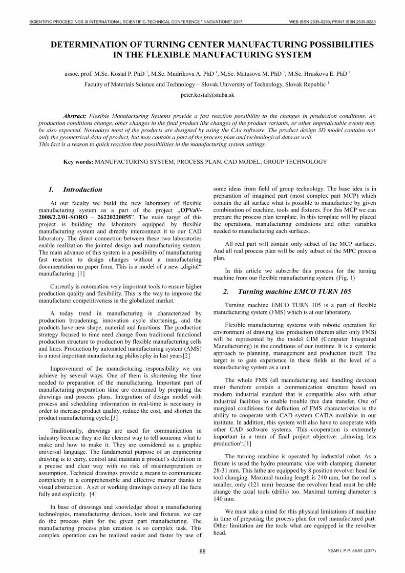
Turning machine EMCO TURN 105 is a part of flexiblemanufacturing system (FMS) which is at our laboratory.
Flexible manufacturing systems with robotic operation forenvironment of drawing less production (therein after only FMS)will be represented by the model CIM (Computer IntegratedManufacturing) in the conditions of our institute. It is a systemicapproach to planning, management and production itself. Thetarget is to gain experience in these fields at the level of amanufacturing system as a unit.
The whole FMS (all manufacturing and handling devices)must therefore contain a communication structure based onmodern industrial standard that is compatible also with otherindustrial facilities to enable trouble free data transfer. One ofmarginal conditions for definition of FMS characteristics is theability to cooperate with CAD system CATIA available in ourinstitute. In addition, this system will also have to cooperate withother CAD software systems. This cooperation is extremelyimportant in a term of final project objective: „drawing lessproduction“.[1]
The turning machine is operated by industrial robot. As afixture is used the hydro pneumatic vice with clamping diameter28-31 mm. This lathe are equipped by 8 position revolver head fortool changing. Maximal turning length is 240 mm, but the real issmaller, only (121 mm) because the revolver head must be ablechange the axial tools (drills) too. Maximal turning diameter is140 mm.
We must take a mind for this physical limitations of machinein time of preparing the process plan for real manufactured part.Other limitation are the tools what are equipped in the revolverhead.
88
SCIENTIFIC PROCEEDINGS III INTERNATIONAL SCIENTIFIC-TECHNICAL CONFERENCE "INNOVATIONS" 2017 WEB ISSN 2535-0293; PRINT ISSN 2535-0285
YEAR I, P.P. 88-91 (2017)
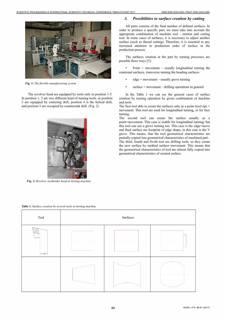
The revolver head are equipped by tools only in position 1-5.In position 1, 2 are two different kind of turning tools, in position3 are equipped by centering drill, position 4 is the helical drill,and position 5 are occupied by countersink drill. (Fig. 2)
3. Possibilities to surface creation by cutting
All parts consists of the final number of defined surfaces. Inorder to produce a specific part, we must take into account theappropriate combination of machine tool - motion and cuttingtool. In some cases of surfaces, it is necessary to adjust anothersurface (such as thread cutting). Therefore, it is essential to payincreased attention to production order of surface in theproduction process
The surfaces creation at the part by turning processes arepossible three ways [5]:
• Point + movement – usually longitudinal turning therotational surfaces, transverse turning the heading surfaces
• edge + movement – usually grove turning
• surface + movement – drilling operations in general
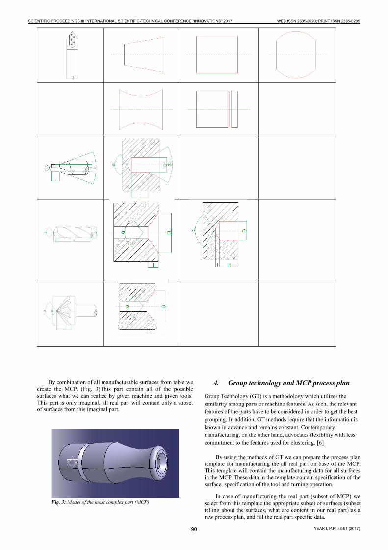
In the Table 1 we can see the general cases of surfacecreation by turning operation by given combination of machineand toolsThe first tool able to create the surfaces only as a point (tool tip) +movement. This tool are used for longitudinal turning, or for faceturning. The second tool can create the surface usually as apoint+movement. This case is usable for longitudinal turning, butthis tool can use a grove turning too. This case is the edge+moveand final surface are footprint of edge shape, in this case is the Vgrove. This means, that the tool geometrical characteristics arepartially copied into geometrical characteristics of machined part.The third, fourth and fiveth tool are drilling tools, so they createthe new surface by method surface+movement. This means thatthe geometrical characteristics of tool are almost fully copied intogeometrical characteristics of created surface.
Table 1. Surface creation by several tools at turning machine
Tool Surfaces
Fig. 1: The flexible manufacturing system
Fig. 2: Revolver toolholder head at turning machine
89
SCIENTIFIC PROCEEDINGS III INTERNATIONAL SCIENTIFIC-TECHNICAL CONFERENCE "INNOVATIONS" 2017 WEB ISSN 2535-0293; PRINT ISSN 2535-0285
YEAR I, P.P. 88-91 (2017)
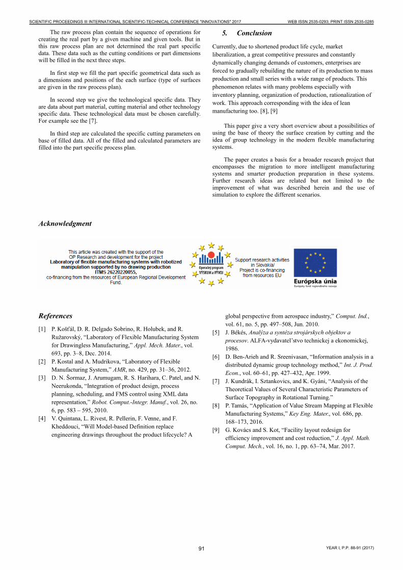
By combination of all manufacturable surfaces from table wecreate the MCP. (Fig. 3)This part contain all of the possiblesurfaces what we can realize by given machine and given tools.This part is only imaginal, all real part will contain only a subsetof surfaces from this imaginal part.
4. Group technology and MCP process plan
Group Technology (GT) is a methodology which utilizes the similarity among parts or machine features. As such, the relevant features of the parts have to be considered in order to get the best grouping. In addition, GT methods require that the information is known in advance and remains constant. Contemporary manufacturing, on the other hand, advocates flexibility with less commitment to the features used for clustering. [6]
By using the methods of GT we can prepare the process plantemplate for manufacturing the all real part on base of the MCP.This template will contain the manufacturing data for all surfacesin the MCP. These data in the template contain specification of thesurface, specification of the tool and turning operation.
In case of manufacturing the real part (subset of MCP) weselect from this template the appropriate subset of surfaces (subsettelling about the surfaces, what are content in our real part) as araw process plan, and fill the real part specific data.
Fig. 3: Model of the most complex part (MCP)
90
SCIENTIFIC PROCEEDINGS III INTERNATIONAL SCIENTIFIC-TECHNICAL CONFERENCE "INNOVATIONS" 2017 WEB ISSN 2535-0293; PRINT ISSN 2535-0285
YEAR I, P.P. 88-91 (2017)
The raw process plan contain the sequence of operations forcreating the real part by a given machine and given tools. But inthis raw process plan are not determined the real part specificdata. These data such as the cutting conditions or part dimensionswill be filled in the next three steps.
In first step we fill the part specific geometrical data such asa dimensions and positions of the each surface (type of surfacesare given in the raw process plan).
In second step we give the technological specific data. Theyare data about part material, cutting material and other technologyspecific data. These technological data must be chosen carefully.For example see the [7].
In third step are calculated the specific cutting parameters onbase of filled data. All of the filled and calculated parameters arefilled into the part specific process plan.
5. Conclusion
Currently, due to shortened product life cycle, market liberalization, a great competitive pressures and constantly dynamically changing demands of customers, enterprises are forced to gradually rebuilding the nature of its production to mass production and small series with a wide range of products. This phenomenon relates with many problems especially with inventory planning, organization of production, rationalization of work. This approach corresponding with the idea of lean manufacturing too. [8], [9]
This paper give a very short overview about a possibilities ofusing the base of theory the surface creation by cutting and theidea of group technology in the modern flexible manufacturingsystems.
The paper creates a basis for a broader research project thatencompasses the migration to more intelligent manufacturingsystems and smarter production preparation in these systems.Further research ideas are related but not limited to theimprovement of what was described herein and the use ofsimulation to explore the different scenarios.
Acknowledgment
References
[1] P. Košťál, D. R. Delgado Sobrino, R. Holubek, and R. Ružarovský, “Laboratory of Flexible Manufacturing System for Drawingless Manufacturing,” Appl. Mech. Mater., vol. 693, pp. 3–8, Dec. 2014.
[2] P. Kostal and A. Mudrikova, “Laboratory of Flexible Manufacturing System,” AMR, no. 429, pp. 31–36, 2012.
[3] D. N. Šormaz, J. Arumugam, R. S. Harihara, C. Patel, and N.Neerukonda, “Integration of product design, process planning, scheduling, and FMS control using XML data representation,” Robot. Comput.-Integr. Manuf., vol. 26, no. 6, pp. 583 – 595, 2010.
[4] V. Quintana, L. Rivest, R. Pellerin, F. Venne, and F. Kheddouci, “Will Model-based Definition replace engineering drawings throughout the product lifecycle? A
global perspective from aerospace industry,” Comput. Ind., vol. 61, no. 5, pp. 497–508, Jun. 2010.
[5] J. Békés, Analýza a syntéza strojárskych objektov a procesov. ALFA-vydavatel’stvo technickej a ekonomickej, 1986.
[6] D. Ben-Arieh and R. Sreenivasan, “Information analysis in adistributed dynamic group technology method,” Int. J. Prod.Econ., vol. 60–61, pp. 427–432, Apr. 1999.
[7] J. Kundrák, I. Sztankovics, and K. Gyáni, “Analysis of the Theoretical Values of Several Characteristic Parameters of Surface Topography in Rotational Turning.”
[8] P. Tamás, “Application of Value Stream Mapping at Flexible Manufacturing Systems,” Key Eng. Mater., vol. 686, pp. 168–173, 2016.
[9] G. Kovács and S. Kot, “Facility layout redesign for efficiency improvement and cost reduction,” J. Appl. Math. Comput. Mech., vol. 16, no. 1, pp. 63–74, Mar. 2017.
91
SCIENTIFIC PROCEEDINGS III INTERNATIONAL SCIENTIFIC-TECHNICAL CONFERENCE "INNOVATIONS" 2017 WEB ISSN 2535-0293; PRINT ISSN 2535-0285
YEAR I, P.P. 88-91 (2017)